

Digital Infrared Wireless Classroom Audio System
Installation and Operating Manual
V 1.9

Remarks:
All rights reserved for translation, reprint or reproduction of this document.
Contents may change without prior announcement.
All technical specifications are guideline data and not guaranteed features.
TAIDEN is not responsible for any damage caused by improper use of this manual.
The equipment must be connected to earth.
This product conforms to the regulations of the European directive 2014/30/EU.
To protect your hearing, please avoid high pressure level on earphones. Adjust to a lower and convenient
level.
If any detailed information needed, please contact your local retailer or TAIDEN service center in your region.
Any feedback, advice and suggestion about the products is appreciated.
In order to extend the life time of whole system, it is strongly recommended that the classroom audio system
be scheduled to shut down every day when not in use.
TAIDEN is the registered trademark of TAIDEN Industrial Co., Ltd.
I

Important Safety Instructions
1. Read these instructions.
2. Keep these instructions.
3. Heed all warnings.
4. Follow all instructions.
5. The apparatus shall not be exposed to dripping or
splashing and that no objects filled with liquids, such as
vases, shall be placed on the apparatus.
6. The MAINS plug serving as a disconnection device,
should be easy to operate.
7. The apparatus should be connected to the MAINS
socket-outlet with protective earth.
8. Clean only with dry cloth.
9. Do not block any ventilation openings. Install in
accordance with the manufacturer’s instructions.
10. Do not install near any heat sources such as radiators,
heat registers, stoves, or other apparatus (including
amplifiers) that produce heat.
11. Do not bypass the safety purpose of the polarized or
grounding-type plug. A polarized plug has two blades
with one wider than the other. A grounding type plug
has two blades and a third grounding prong. The wide
blade and the t hird pron g are p rovided for your safety . If
the provided plug does not fit into your outlet, consult
an electrician for replacement of the obsolete outlet.
12. Protect the power cord from being walked on or
pinched particularly at plugs, convenience receptacles,
and the point where they exit from the apparatus.
13. Only use attachments/accessories specified by the
manufacturer.
14. Do not leave the battery near the fire or under an
environment over 60 ºC (such as under direct sunlight
in the car), otherwise it may damage the protection
circuit of the battery and cause fire, explosion, leakage
or heat generation.
15. Unplug this apparatus during lightning storms or when
unused for long periods of time.
16. Refer all servicing to qualified service personnel.
Servicing is required when the apparatus has been
damaged in any way, such as power-supply cord or
plug is damaged, liquid has been spilled or objects
have fallen into the apparatus, the apparatus has been
exposed to rain or moisture, d oes not o perate normally,
or has been dropped.
17. Do not place the equipment on any uneven or unstable
stand; original product package or appropriate package
should be used to avoid damage caused by strong
impacts during transportation.
18. Power supply cords:
AC 100 V-240 V 50 Hz/ 60 Hz
19. The quantity of connected transceivers in one system
should not exceed prescribed quantity. For service,
please contact the nearest TAI DEN Serv ice Center.
20. All TAIDEN products are guaranteed for definite time
(see the WARRANTY CARD for details) excluding the
following cases:
A. All damage or malfunction caused by human
negligence;
B. Damage or malfunction caused by improper
operating by operator;
C. Parts d am age or lo ss ca us ed by disassembling the
product by non-authorized personnel.
21. Use ONLY specified connection cable to connect the
system equipment.
22. Upon receipt of the product, please fill out the Warranty
Card enclosed and post it to TAIDEN Service Center
nearby in your region.
This label appears on the rear of the unit due to space limitations
The lightning flash with an arrowhead symbol, with
an equilateral triangle, is intended to alert the user to
the presence of uninsulated ‘dangerous voltage’
within the products enclosure that may be of
sufficient magnitude to constitute a risk of electric
shock to persons.
The exclamation mark within an equilateral triangle is
intended to alert the user to the presence of
important operating and maintenance (servicing)
instructions in the literature accompanying the
appliance.
CAUTION: To reduce the risk of electric shock,
DO NOT open covers, no useable serviceable
parts inside. Refer servicing to qualified service
personnel only.
WARNING: These apparatuses shall not be
exposed to dripping or splashing and no
objects filled with liquids, such as vases
shall be placed on the apparatus.
II

Important Safety Instructions
Attention: Installation should be performed by
qualified service personnel only in accordance
with the National Electrical or applicable local
codes.
Power Disconnect: Units with or without ON – OFF
switch have power supplied to the unit whenever the
power cord is inserted into the power source;
however, the unit is operational only when the ON –
OFF switch i s in the ON posi tion. The p ower cor d is
the main power disconnect for all units
WARNING: To reduce the risk of electric
shock, DO NOT expose units to rain or
moisture.
WARNING:
The apparatus should be
connected to a mains socket outlet with a
protective earthing connection.
III

Lithium battery safety precautions
To change battery please power off and take off the battery immediately.
Keep the battery away from heat sources to prevent fire or explosion.
Do not use a battery that is leaking, deformed, discolored or overheats.
Take extra precautions to keep a leaking battery from fire.
Do not use a battery that emits odor or smoke.
Do not solder, di sassemble, puncture or def orm the battery, otherwise, it may damage the protection circuit of the
battery and cause fire, leakage or explosion.
Do not short-circuit the positive and negative electrode with wire or other metal objects, otherwise it may cause fire,
explosion, leakage or heat generation.
Do not store or transport the battery with metal objects (such as necklace or hair grip), otherwise it may cause fire,
explosion, leakage or heat generation.
Do not heat the battery or throw it into fire, otherwise it may damage the safety valve or the protection circuit of the
battery and may cause fire or explosion.
Do not put the battery in the water or moisten the electrode of the battery, otherwise it may corrode the battery and
cause fire, explosion, leakage or heat generation.
Be careful to put the battery into the charging case with correct electrode position, otherwise it may cause fire,
explosion, leakage or heat generation.
Do not leave the battery near the fire or under an environment over 60 ºC (such as in the car from di rect sunlight),
otherwise it may damage the protection circuit of the battery and cause fire, explosion, leakage or heat generation.
Please charge the battery with the dedicated base plate, using other charging unit may cause fire, explosion,
leakage or heat generation.
Please use the battery in assigned unit, otherwise it may cause fire, explosion, leakage or heat generation.
Do not drop or shock the battery, otherwise it may damage the protection circuit of the battery and cause fire,
explosion, leakage or heat generation.
If battery contents get into eyes it may cause blurred vision. DO NOT rub. Rinse with clear water immediately and
consult a doctor.
If the battery leaks onto skin or clothing, wash the area immediately with clean water to avoid skin injury and fabric
damage.
It will result in low battery and may damage the battery if the battery is not used for a long time. Please take off the
battery, and fully charge the battery for every three months.
IV

Contents
Installation & User Guide .........................................................................................................VIII
Chapter 1 System introduction ................................................................................................... 1
1.1 Overview ...................................................................................................................................................................... 1
1.2 Functions and features ................................................................................................................................................ 3
1.3 System technology ...................................................................................................................................................... 4
1.3.1 Basic system concept .................................................................................................................................................. 4
1.3.2 IR radiation .................................................................................................................................................................. 4
1.3.3 Carriers and channels ................................................................................................................................................. 4
1.4 Factors impacting infrared signal transmission ............................................................................................................ 5
1.4.1 Ambient lighting ........................................................................................................................................................... 5
1.4.2 Objects, surfaces and reflections ................................................................................................................................ 5
Chapter 2 Digital IR Wireless System Main Unit ........................................................................ 6
2.1 Overview ...................................................................................................................................................................... 6
2.2 Functions and indications ............................................................................................................................................ 7
2.3 Installation .................................................................................................................................................................... 9
2.4 Connection ................................................................................................................................................................. 10
2.4.1 To other auxiliary devices .......................................................................................................................................... 10
2.4.2 To recording device ................................................................................................................................................... 10
2.4.3 To speaker ................................................................................................................................................................ 10
2.4.4 To central control system .......................................................................................................................................... 11
2.5 Configuration and operation ...................................................................................................................................... 12
2.5.1 Mic Sens. .................................................................................................................................................................. 12
2.5.2 Line In Vol. ................................................................................................................................................................ 13
2.5.3 EQ Setting ................................................................................................................................................................. 13
2.5.4 Auto Fade .................................................................................................................................................................. 13
2.5.5 FB Suppress ............................................................................................................................................................. 13
2.5.6 Line In 1 Set. ............................................................................................................................................................. 14
2.5.7 Language .................................................................................................................................................................. 14
2.5.8 Factory Reset ............................................................................................................................................................ 14
2.5.9 About ......................................................................................................................................................................... 14
2.6 USB LINK .................................................................................................................................................................. 16
2.6.1 Installation of USB LINK ............................................................................................................................................ 16
2.6.2 Digital audio input ...................................................................................................................................................... 17
2.6.3 Digital audio output .................................................................................................................................................... 18
2.6.4 PPT-page switch ....................................................................................................................................................... 19
Chapter 3 Digital infrared receiver ............................................................................................ 20
3.1 Overview .................................................................................................................................................................... 20
3.2 Functions and indications .......................................................................................................................................... 20
3.3 Position planning ....................................................................................................................................................... 21
3.3.1 Precautions in planning the digital infrared receiver .................................................................................................. 21
3.3.2 Example for planning the receiver ............................................................................................................................. 22
3.4 Installation .................................................................................................................................................................. 23
V

3.4.1 Ceiling mounted ........................................................................................................................................................ 23
3.4.2 Tripod moun ted ......................................................................................................................................................... 25
3.4.3 Wall mounted (Adjustable angle) ............................................................................................................................... 26
3.5 Connecting to main unit ............................................................................................................................................. 27
Chapter 4 Economical Digital infrared Wireless System Combo Unit ....................................... 28
4.1 Overview .................................................................................................................................................................... 28
4.2 Functions and indications .......................................................................................................................................... 28
4.3 Installation .................................................................................................................................................................. 29
4.3.1 Ceiling mounted ........................................................................................................................................................ 29
4.3.2 Tripod moun ted ......................................................................................................................................................... 31
4.3.3 Wall mounted (Adjustable angle) ............................................................................................................................... 33
4.4 Connection ................................................................................................................................................................. 34
4.4.1 To loudspeaker ......................................................................................................................................................... 34
4.4.2 To other extension receiver (TES-5600R) ................................................................................................................. 34
4.4.3 To other auxiliary devices .......................................................................................................................................... 34
4.5 Operation ................................................................................................................................................................... 35
Chapter 5 Digital infrared wireless microphone ........................................................................ 36
5.1 Overview .................................................................................................................................................................... 36
5.2 Functions and indicators ............................................................................................................................................ 37
5.3 Infrared service area .................................................................................................................................................. 39
5.4 Operation ................................................................................................................................................................... 40
5.4.1 TES-5602A (handheld type) ...................................................................................................................................... 40
5.4.2 TES-5603(B) (pendant type) ..................................................................................................................................... 41
Chapter 6 Accessories ............................................................................................................. 44
6.1 Power Adapter ........................................................................................................................................................... 44
6.2 Dedicated Cable ........................................................................................................................................................ 45
6.3 Speaker ..................................................................................................................................................................... 46
6.4 TES-5600ZJ1 ............................................................................................................................................................. 48
6.5 TES-5600ZJ2 ............................................................................................................................................................. 48
6.6 TES-5600CHG Charging Unit .................................................................................................................................... 48
6.7 Charging station ......................................................................................................................................................... 49
6.8 Li-ion Rechargeable battery ....................................................................................................................................... 49
6.9 TES-5600RZJ ............................................................................................................................................................ 50
Chapter 7 Fault diagnosis ........................................................................................................ 51
7.1 Digital infrared wireless microphone .......................................................................................................................... 51
7.2 Digital infrared wireless system main unit .................................................................................................................. 51
7.3 USB LINK .................................................................................................................................................................. 52
Chapter 8 Technical data .......................................................................................................... 53
8.1 System specification .................................................................................................................................................. 53
8.2 Digital infrared wireless system main unit .................................................................................................................. 54
8.3 Digital infrared receiver .............................................................................................................................................. 55
8.4 Economical digital infrared wireless system combo unit ............................................................................................ 56
8.5 Digital infrared wireless microphone .......................................................................................................................... 57
VI

8.6 Power adapter ........................................................................................................................................................... 58
8.7 Charging unit ............................................................................................................................................................. 58
8.8 Connection details ..................................................................................................................................................... 59
Appendix .................................................................................................................................. 60
AppendixⅠ: Connect RG-59 Coaxial-cable to TES-5600R ............................................................................................. 60
AppendixⅡ: Soldering of BNC connector and RG-59 Coaxial-cable .............................................................................. 60
VII

Installation & User Guide
About this manual:
This manual is a comprehensive guide to the
installation and operation of TAIDEN TES-5600 series
digital infrared wireless classroom audio system. It
includes the detailed description of the function and
interface of the TES-5600 system components, system
connection and installation, system set-up and
operation.
The manual is divided into the following chapters:
Chapter 1: Introduction
Introduction to the TES-5600 system, as well as to the
structure, technical principle, and aspects of system
planning.
Chapter 2: Digital infrared w ireless system main
unit
Detailed description of functions, connection,
configuration and operation of digital infrared wireless
system main unit.
Chapter 3: Digital infrared receiver
Detailed description of functions, installation and
connection of digital infrared receiver.
Chapter 4: Economical digital infrared wireless
system combo unit
Detailed description of functions, connection,
installation and operation of economical digi tal i nfr are d
wireless system combo unit.
Chapter 5: Digital infrared wireless microphone
Detailed description of functions and operation of
digital infrared wireless microphone.
Chapter 6: Peripheral equipment and
accessories
Detailed description of power adapter, coaxial-cable,
BNC interface, speaker, and etc..
Chapter 7: Fault diagnosis
Trouble-shooting guide for simple faults.
Chapter 8: Technical data
Mechanical and electrical details of TES-5600
equipment.
VIII

Installation & User Guide
This manual is applicable to:
Digital IR Wireless System Main Unit
TES-5600MA/02P
Digital Infrared Wireless System Main Unit (supports 2
wireless microphones, built-in amplifier, supports 4
speakers, with phantom power)
TES-5600MAU/02P
Digital Infrared Wireless System Main Unit (supports 2
wireless microphones, built-in amplifier, supports 4
speakers, USB interface for digital audio input/output,
with phantom power)
TES-5600MB/02P
Digital Infrared Wireless System Main Unit (supports 2
wireless microphones, with phantom power)
TES-5600MBU/02P
Digital Infrared Wireless System Main Unit (supports 2
wireless microphones, USB interface for digital audio
input/output, with phantom power)
Digital Infrared Receiver
TES-5600R
Digital Infrared Receiver
TES-5600RN
Digital Infrared Receiver (enlargement type)
Economical Digital IR Wireless System Combo
Unit
TES-5630M
Economical Digital Infrared Wireless System Combo
Unit (supports 2 wireless microphones, built-in
amplifier, supports 2 speakers)
TES-5630MA
Economical Digital Infrared Wireless System Combo
Unit (supports 1 wireless microphones, built-in
amplifier, supports 2 speakers)
Digital IR Wireless Microphone
TES-5602A
Digital IR Wireless Microphone (handheld type,
rechargeable battery)
TES-5603
Digital IR Wireless Microphone (pendant type,
rechargeable battery or AA alkaline cell)
TES-5603B
Digital IR Wireless Microphone (pendant type,
rechargeable battery)
Power Adapter
TES-ADP5V Power Adapter (DC 5 V, 2.0 A)
TES-ADP15V Power Adapter (DC 15 V, 2.4 A)
TES-ADP24V Power Adapter (DC 24 V, 2.7 A)
TES-ADP24VN Power Adapter (DC 24 V, 1.5 A)
TES-ADP5V6A Power Adapter (DC 5 V, 6.0 A)
Tripod
TES-5600ZJ1 Microphone Stand
TES-5600ZJ2 Microphone/Receiver Stand
TES-5600RZJ Fixing Bracket
Rechargeable battery
TES-5600BAT
Li-ion Rechargeable Battery (18500, 3.7 V, 1600mAh)
TES-5603BAT
Li-ion Rechargeable Battery (14430, 3.7 V, 700mAh)
Charging unit
HCS-5600CHG Charging Unit
HCS-5600CS Charging Station
HCS-5602CHG/09 Charging Station
HCS-5603CHG/09 Charging Station
Dedicated Cable
CBL5600-10 10 m Dedicated Receiver Cable
CBL5600-20 20 m Dedicated Receiver Cable
CBL5600-30 30 m Dedicated Receiver Cable
CBL5600-40 40 m Dedicated Receiver Cable
CBL5600-50 50 m Dedicated Receiver Cable
CBL-SPK Speaker Cable
CBL-SPK2 Speaker Cable
Power Adapter Extension Cable (for TES-ADP24VN)
Cable Connection Terminal (for TES-ADP24VN
extension cable)
IX
Chapter 1 System introduction
1.1 Overview
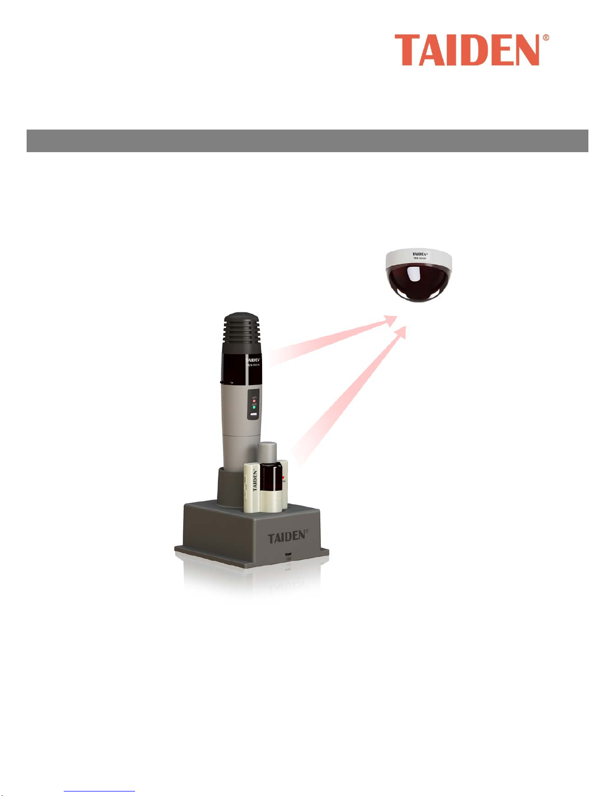
TAIDEN TES-5600 s eries product is a digital infrared
wireless classroom audio system. This system
provides an ideal audio solution for teaching
environment thanks to its capabilities of
anti-interference, privacy assurance,
easy-manageability and audio clarity, etc.
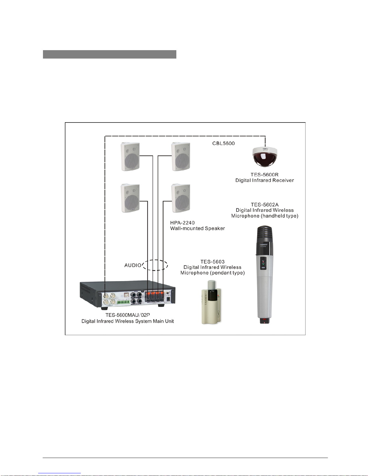
The system consists of one digital infrared wireless
main unit, one or more digital infrared receivers,
speakers and up to 4 digital infrared wireless
microphones.
Figure 1.1 System overview
The system is composed of one or more of the
following:
Digital IR Wireless System Main Unit
TES-5600MA/02P
Digital Infrared Wireless System Main Unit (supports 2
wireless microphones, built-in amplifier, supports 4
speakers, with phantom power)
TES-5600MAU/02P
Digital Infrared Wireless System Main Unit (supports 2
wireless microphones, built-in amplifier, supports 4
speakers, USB interface for digital audio input/output,
with phantom power)
1

TES-5600MB/02P
Digital Infrared Wireless System Main Unit (supports 2
wireless microphones, with phantom power)
TES-5600MBU/02P
Digital Infrared Wireless System Main Unit (supports 2
wireless microphones, USB interface for digital audio
input/output, with phantom power)
Digital Infrared Receiver
TES-5600R
Digital Infrared Receiver
TES-5600RN
Digital Infrared Receiver (enlargement type)
Economical Digital IR Wireless System Combo
Unit
TES-5630M
Economical Digital Infrared Wireless System Combo
Unit (supports 2 wireless microphones, built-in
amplifier, supports 2 speakers)
TES-5630MA
Economical Digital Infrared Wireless System Combo
Unit (supports 1 wireless microphones, built-in
amplifier, supports 2 speakers)
Digital IR Wireless Microphone
TES-5602A
Digital IR Wireless Microphone (handheld type,
rechargeable battery)
TES-5603
Digital IR Wireless Microphone (pendant type,
rechargeable battery or AA alkaline cell)
TES-5603B
Digital IR Wireless Microphone (pendant type,
rechargeable battery)
Power Adapter
TES-ADP5V Power Adapter (DC 5 V, 2.0 A)
TES-ADP15V Power Adapter (DC 15 V, 2.4 A)
TES-ADP24V Power Adapter (DC 24 V, 2.7 A)
TES-ADP24VN Power Adapter (DC 24 V, 1.5 A)
TES-ADP5V6A Power Adapter (DC 5 V, 6.0 A)
Tripod
TES-5600ZJ1 Microphone Stand
TES-5600ZJ2 Microphone/Receiver Stand
TES-5600RZJ Fixing Bracket
Rechargeable battery
TES-5600BAT
Li-ion Rechargeable Battery (18500, 3.7 V, 1600mAh)
TES-5603BAT
Li-ion Rechargeable Battery (14430, 3.7 V, 700mAh)
Charging unit
HCS-5600CHG Charging Unit
HCS-5600CS Charging Station
HCS-5602CHG/09 Charging Station
HCS-5603CHG/09 Charging Station
Dedicated Cable
CBL5600-10 10 m Dedicated Receiver Cable
CBL5600-20 20 m Dedicated Receiver Cable
CBL5600-30 30 m Dedicated Receiver Cable
CBL5600-40 40 m Dedicated Receiver Cable
CBL5600-50 50 m Dedicated Receiver Cable
CBL-SPK Speaker Cable
CBL-SPK2 Speaker Cable
Power Adapter Extension Cable (for TES-ADP24VN)
Cable Connection Terminal (for TES-ADP24VN
extension cable)
2

1.2 Functions and features
1. The World’s first Digital infrared wireless
classroom audio system operating
TAIDEN
dirATC technology - digital infrared Audio
Transmission and Control technology
2. Audio clarity
World pioneering infrared technology enables
excellent audio quality:
Frequency Response: 50 Hz to 20 kHz
Signal to Noise: > 85 dBA
THD: <0.06 %
Improved audio clarity allows lecturers to speak in a
normal pitch, protecting them from loss of voice
Clear voices also helps students stay concentrated,
thus increasing learning efficiency
3. USB Link function
Digital audio input/output:
a) lossless sound recording during class on
computer;
b) lossless transmission of streaming audio from
computer
Cooperating with the TES-5603(B) for remote
PPT-page switch control
4. High interference resistance
No crosstalk and interference between classrooms
when their systems are used at the same time
Neither radio interference inherent to radio
wave-based wireless communications nor radio
radiation
The advanced digital infrared technology allows
perfect resistance against HF-driven lighting
interference and good operation in sunlight
5. Easy manageability
Digital infrared microphones can be used in different
classrooms without channel matching. Switch on
and talk, easy and convenient
Infrared microphones exclusive for each lecturer,
which is more convenient and hygienic
6. No radiation
Not restricted by radio frequency licensing thus
saving radio frequency resources
Free from radiation since there is no radio power
output
7. Multiple Emergency Alarms
Alarm can be triggered by either the emergency
switch on the main unit, central system or by the
pendant microphone to meet different needs of the
customers
After the alarm is activated, emergency signal can
be transmitted to central system. The signal can also
control the electrical level to connect relay or alarm
devices of a third party, which is highly flexible
The lecturer can trigger the alarm from the pendant
microphone unnoticed to send the emergency signal
to campus security center
3
1.3 System technology
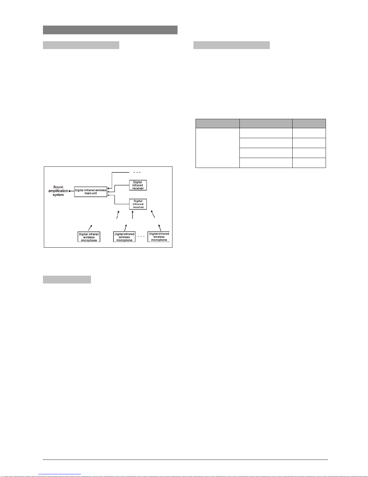
1.3.1 Basic system concept
The system composition of TES-5600 digital infrared
wireless classroom audio system is shown in figure 1.2.
It is composed of:
Digital infrared wireless microphones
Digital infrared wireless main unit for system control
Digital infrared receiver(s) for connection to main
unit
The digital infrared receiver(s) receive infrared signals
from every digital infrared wireless microphone and
convert the signals into audio or control signals which
are transmitted to the main unit.
Figure 1.2 The basic system concept
1.3.2 IR radiation
Audio and control signals of TES-5600 are transmitted
as modulated infrared light. Infrared radiation is part of
the electro-magnetic spectrum, which is composed of
visible light, radio waves and other types of radiation.
Its wavelength is longer in comparison with the
wavelength of visible light.
Infrared light cannot pass through opaque walls and
ceilings thus guarantees privacy of the meeting by
avoiding being intercepted or disturbed. In addition,
infrared light has no radio radiation and a license is not
required when operating infrared light systems.
1.3.3 Carriers and channels
TAIDEN TES-5600 digital infrared wireless conference
system adopts 1-8 MHz wave band. This wave band is
suitable for the transmission of wide band audio and
corresponding signals. TES-5600 uses 4 frequency
points of BANDⅢand BANDⅣ in IEC 61603(please
refer to table 1.1.)
Route
Channel
Frequency
From
microphone to
main unit via
receiver
channel 1 1.0 MHz
channel 2 1.6 MHz
channel 3 2.3 MHz
channel 4 3.0 MHz
Table 1.1 Channels and corresponding frequencies in
TES-5600 system
4

1.4 Factors impacting infrared signal transmission
To benefit from the advantages of a digital infrared
wireless classroom audio system the signals should be
transmitted undisturbed. This is achieved by using
digital infrared receiver well positioned and sufficient in
quantity to ensure uniform and adequate infrared
radiation for all microphones.
When planning a digital infrared wireless classroom
audio system, several aspects influencing the
uniformity and quality of the infrared signal should be
considered. These are discussed in the next sections.
1.4.1 Ambient lighting
TES-5600 system adopts 1-8 MHz wave band, and has
a good anti-interference performance (see figure 1.3).
Figure 1.3 Digital infrared classroom audio system with
1-8 MHz wave band can avoid high frequency lights
disturbance
For classrooms with large, unscreened windows,
multi-receiver operation should be considered. For
outdoor using, a site test wil l be required to determine
the needed amount of receivers. With sufficient
receivers, perfect signal transmission can be fulfilled
even in bright sunlight.
1.4.2 Objects, surfaces and reflections
Just like visible light, infrared radiation is reflected from
hard surfaces and refracted by hyaloid (glassy or
transparent appearance) items. Objects in the
classroom as well as structure of the walls and ceilings
will influence the distribution of infrared light.
Infrared radiation is reflected from almost all hard
surfaces. Smooth, bright or shiny surfaces reflect well.
Dark or rough surfaces absorb a large part of the
infrared energy. Usually, surfaces opaque to visible
light are also opaque to infrared radiation.
Shadows from walls and furniture will influence the
transmission of infrared light. This can be solved by
using a sufficient quantity of receivers. They should be
positioned in a manner to provide an infrared field
strong enough to cover the whole teaching area.
5

Chapter 2 Digital IR Wireless System Main Unit
2.1 Overview
TES-5600M series digital infrared wireless system
main unit is the heart of the TES-5600 wireless
classroom audio system. The main unit can be
connected to digital infrared receivers and recording
devices and:
display system function configuration
display system status
fulfill automatic classroom audio controlling
Each TES-5600MA/MB main unit can be connected to
4 receivers at most and the maximal number of digital
infrared wireless microphone is 2. 4 speakers at most
can be connected to the TES-5600MA main unit
directly.
TES-5600M is half-rack width and suitable for either
tabletop or 19-inch rack mounting (two main units
abreast) using. Four bottom studs (for tabletop) and
two brackets (for rack mounting) are supplied.
Types:
TES-5600MA/02P
Digital Infrared Wireless System Main Unit (supports 2
wireless microphones, built-in amplifier, supports 4
speakers, with phantom power)
TES-5600MAU/02P
Digital Infrared Wireless System Main Unit (supports 2
wireless microphones, built-in amplifier, supports 4
speakers, USB interface for digital audio input/output,
with phantom power)
TES-5600MB/02P
Digital Infrared Wireless System Main Unit (supports 2
wireless microphones, with phantom power)
TES-5600MBU/02P
Digital Infrared Wireless System Main Unit (supports 2
wireless microphones, USB interface for digital audio
input/output, with phantom power)
6
2.2 Functions and indications
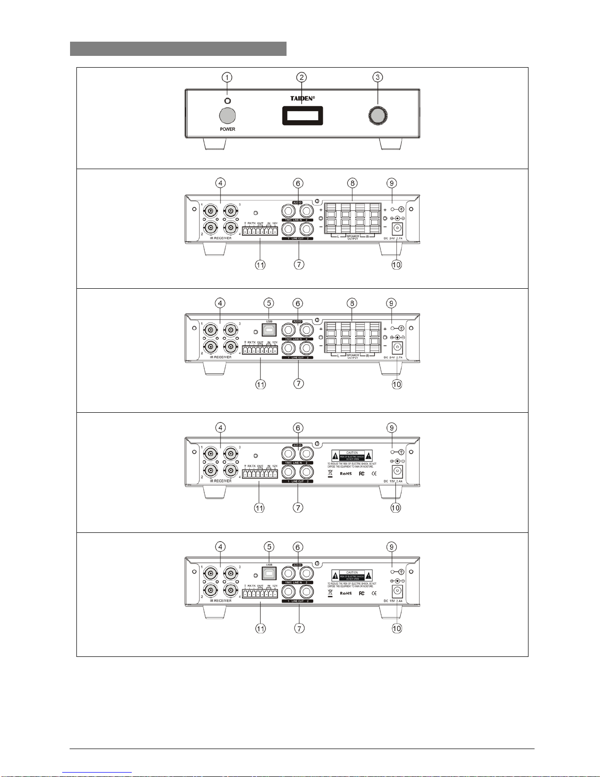
Front panel of TES-5600M main unit
Rear panel of TES-5600MA/P main unit
Rear panel of TES-5600MAU/P main unit
Rear panel of TES-5600MB/P main unit
Rear panel of TES-5600MBU/P main unit
Figure 2.1 Digital infrared wireless system main unit
7

Figure 2.1:
1. “POWER” button and indicator
2. Menu display
128×36 OLED, displays main unit status and
configuration menu.
3. Knob
For menu operation;
For master volume control.
4. Receiver interfaces (1-4, BNC)
5. Device USB interface
For firmware upgrade
6. MIC/LINE IN (
φ6.4mm, balance/difference input)
LINE IN 1 can offer phantom power when being
used for microphone input
7.LINE OUT (
φ6.4mm, balance/difference output)
8. Speaker interface (4 groups)
9. GND
10. Power supply
11. Phoenix interface
For connecting network central control system
For alarm
8
2.3 Installation
TES-5600M series digital infrared wireless system
main unit is half-rack width and can be fixed in a
standard 19-inch cabinet single or for two main units
abreast.
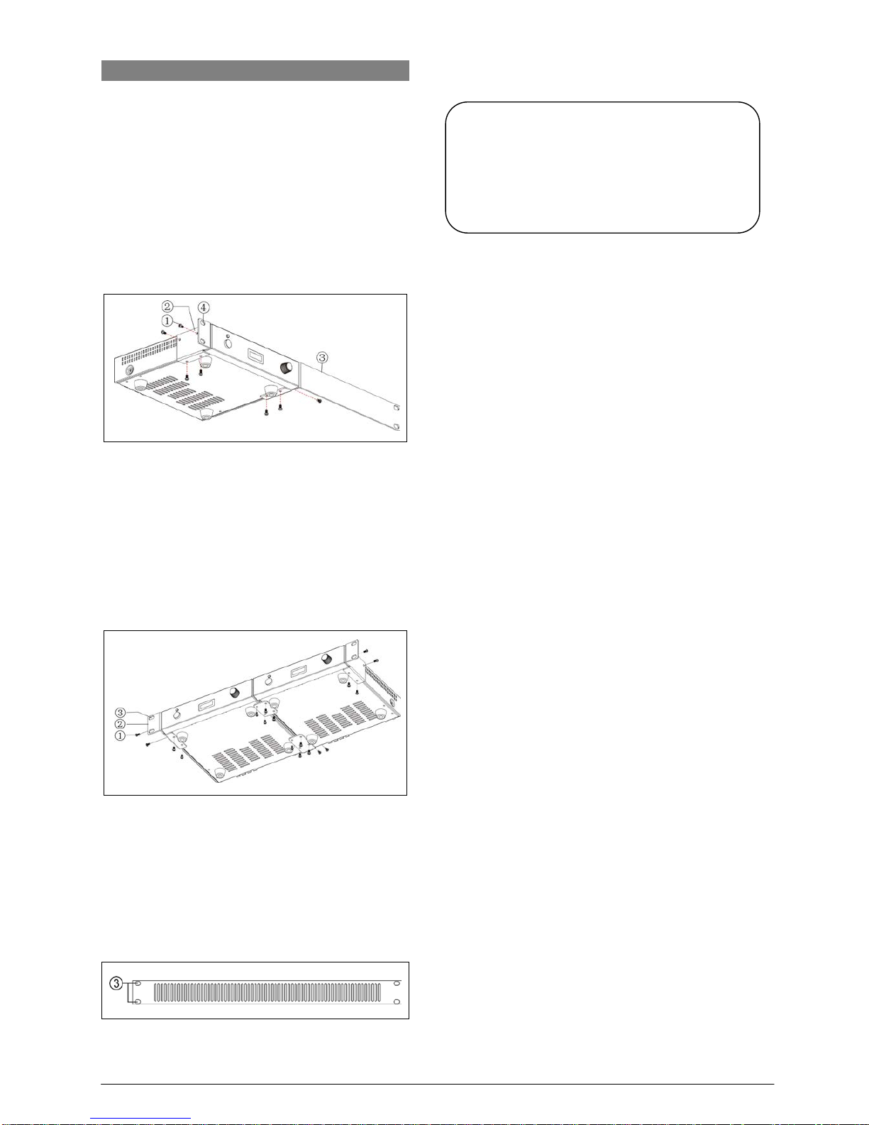
Installation of single main unit
First unscrew the lateral screws ① from the housing.
Then fasten the brackets ② and ③ with these screws
and put the main unit in the cabinet. Finally fix the four
holes ④ up with screws (see Figure 2.2).
Figure 2.2 Installation of single digital infrared wireless
system main unit
Installation of two main units abreast
First unscrew the screws ① on the lateral and bottom
from the housing. Then fasten the four brackets ② with
these screws and put the main units in the cabinet.
Finally fix the four holes
③ up with screws (see Figure
2.3).
Figure 2.3 Installation of two digital infrared wireless
system main units abreast
In addition, 1U metal stripes are included as decoration
to be installed between the main units in the cabinet. It
is also good for the ventilation and cooling off. Fix up
the four holes
③ with screws (see Figure 2.4).
Figure 2.4 Decoration of cabinet
Note:
There are vents in the both sides and bottom of
the main unit. Do not cover the vents and
please save enough area to keep good
ventilation for the equipment.
9
2.4 Connection
Several typical system connections of TES-5600M
series main unit will be introduced in this section,
including connection:
To other auxiliary devices
To recorder device
To speaker
To central control system
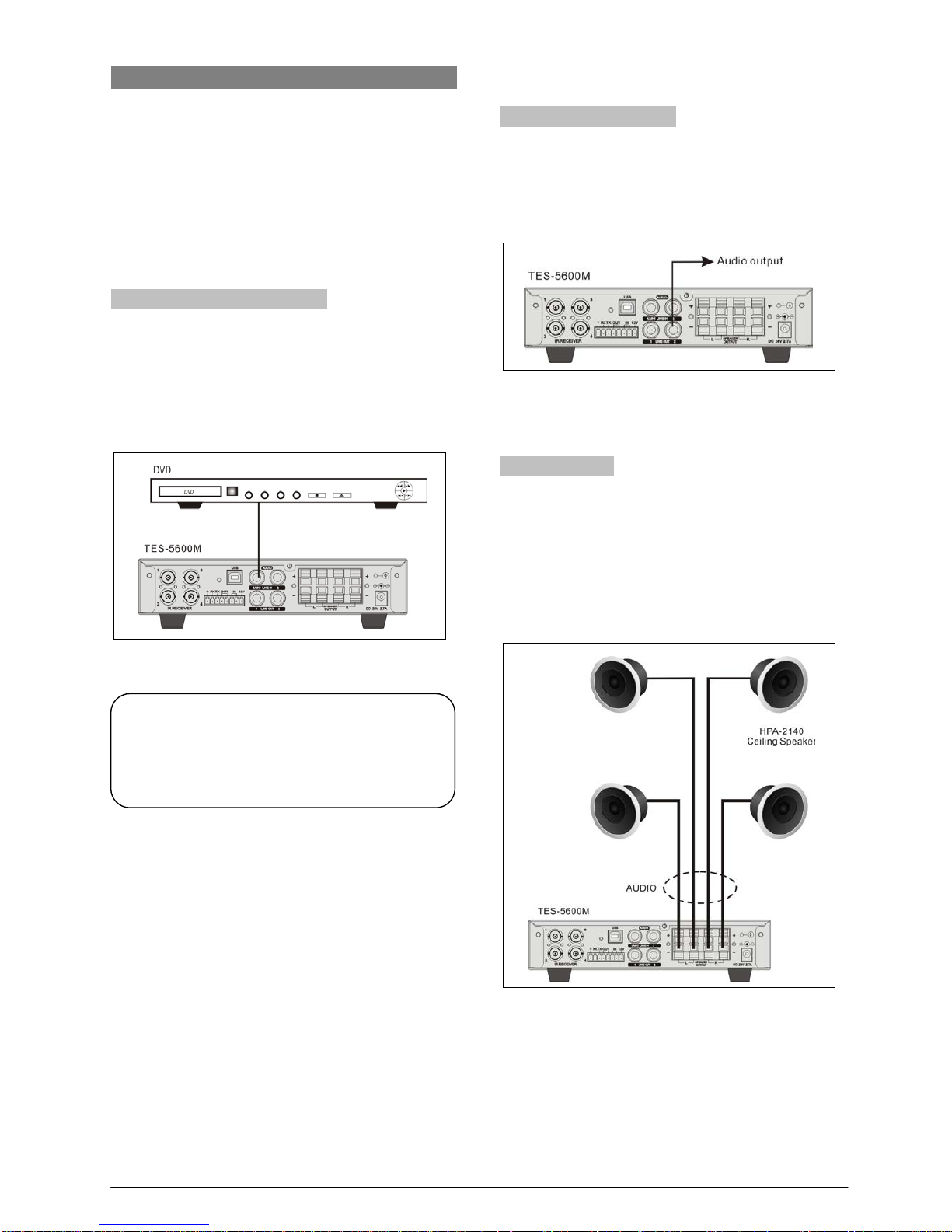
2.4.1 To other auxiliary devices
Digital infrared wireless system main unit can be
connected to an external audio device through LINE IN
interface. The external audio signal is now available at
the LINE OUT and speakers.
Figure 2.5 Main unit connecti ng to ex t ernal audio dev ice
through “LINE IN” interface
2.4.2 To recording device
Digital infrared wireless system main unit has LINE
OUT interface which can be connected to recording
devices.
Figure 2.6 Digital infrared wireless system main unit
connecting to recording device
2.4.3 To speaker
TES-5600MA series digital infrared wireless system
main unit has four groups o f speaker interface w hich
can be connected to speakers directly. Use an audio
cable to connect “SPEAKER OUTPUT” of
TES-5600MA to the input interface of speaker.
Figure 2.7 Digital infrared wireless system main unit
connecting to speakers
Note:
The LINE IN 1 interface of TES-
5600M/P can
also be connected to a microphone and offer
phantom power.
10
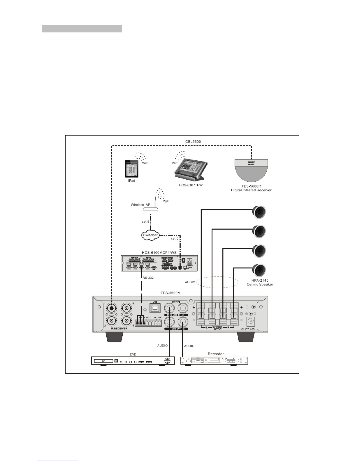
2.4.4 To central control system
TES-5600M has the functions of microphone controlling
and volume adjusting. Also,
TAIDEN TES-5600 digital
infrared wireless classroom audio system and TAIDEN
HCS-6100 intelligent central control system can be joined
together seamlessly, connecting various devices,
hardware and environment equipment from different
manufacturers together. The central control system can
operate the teaching devices through wired Ethernet or
wireless communication by wired/wireless touch panel.
Features include power controlling, system PA volume
controlling and controlling of various electric devices,
such as DVD, recorder, etc. RS-232C interface is
available. Remote controlling, even from distant places,
can be achieved through LAN or internet.
Multiform functions can be realized by such system
configuration:
Digital infrared wireless classroom audio;
Control the volume of microphones;
Control the volume of speakers;
Control the devices in the classroom.
Figure 2.8 Digital infrared wireless system main unit connecting to central control system
11
2.5 Configuration and operation
Digital infrared wireless system main unit can be
configured and set up through menu operation with knob.
All menu items operation will be introduced one by one in
this section.
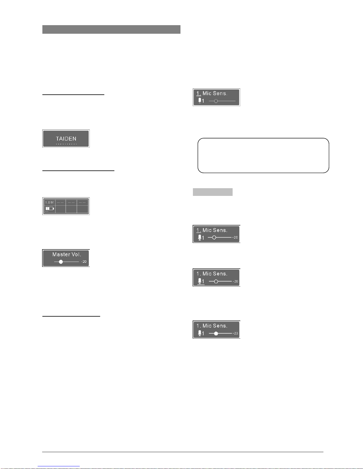
A) Starting initialization
Switch on and press the "POWER" button, the
TES-5600M digital infrared wireless system main unit will
start initialization:
B) Initial interface on OLED
The initial interface on the OLED includes channel status
and microphone battery capacity.
Under initial interface of TES-5600MA, switch the
knob to enter the master volume control menu;
Rotate the knob to adjust the volume(range: -30 dB
to 0 dB)
, and then keep pre ssing the knob to con firm
and turn back to the initial interface.
C) Access main menu
Pressing the knob under initial interface will go to main
menu, which includes ten menu items:
“Mic. Sens.”
“Line In Vol.”
“EQ Setting”
“Auto Fade”
“FB Suppress”
“Line In 1 Set.”
“Language”
“Factory Reset”
“About”
Rotate the knob to switch submenus one by one;
Press the knob to go to the corresponding
submenus.
2.5.1 Mic Sens.
Adjust the sensitivity of the digital infrared wireless
microphones range: -∞ (mute), -30 dB to 0 dB.
1. Press the knob to enter the microphone selection
interface;
2. Rotate the knob to select a microphone, and then
press the knob to enter the sensitivity adjusting interface,
the hollow pellet will turn solid;
3. Adjust the sensitivity by rotating the knob and then
press the knob to confirm.
Note:
Keep pressing the knob to return to the OLED
initial interface under any menu.
12
 Loading...