

Taiden HCS-3938C, HCS-3938CF, EP-820AS, HCS-3938DF, EP-829 Installation And Operating Manual
...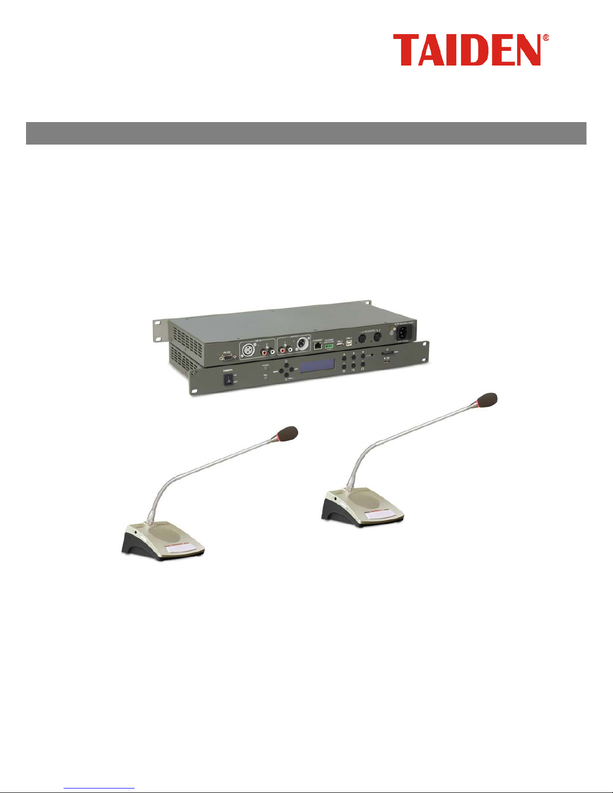
HCS-3900 Series Economical Digital Conference System
Installation and Operating Manual
V 1.5
Economical Digital Conference System

Remarks:
All rights reserved for translation, reprint or reproduction
Contents may change without prior announcement
All technical specifications are guideline data and not guaranteed features
Taiden Co., Ltd. is not responsible for any damage caused by improper use of this manual
The equipment must be connected to earth!
This product conforms to the rules of the European directive 2014/30/EU.
To protect your hearing, avoid high pressure level on earphones. Adjust to a lower and convenient level.
If any detailed information is needed, please contact your local agent or TAIDEN service center in your region.
Any feedback, advice and suggestion about the products is appreciated.
In order to extend the life time of whole system, we strongly recommend that the conference system be
scheduled to shut down every day in the evening when not in use.
TAIDEN is the registered trademark of TAIDEN Industrial Co., Ltd.
I
Important Safety Instructions
1. Read these instruct ions.
2. Keep these instructions.
3. Heed all warnings.
4. Follow all instructions.
5. The apparatus shall not be exposed to dripping or
splashing and that no objects filled with liquids, such
as vases, shall be placed on the apparatus.
6. The MAINS plug serving as a disconnection device
should be easy to operate.
7. The apparatus should be connected to the MAINS
socket-outlet with protective earth.
8. Clean only with dry cloth.
9. Do not block any ventilation openings. Install in
accordance with the manufacturer’s instructions.
10. Do not i nst all ne ar any h eat s ources such as radiator s,
heat registers, stoves, or other apparatus (including
amplifiers) that produce heat.
11. Do not defeat the safety purpose of the polarized or
grounding-type plug. A polarized plug has two blades
with one wider than the other. A grounding type plug
has two blades and a third grounding prong. T he wide
blade and the third pro ng ar e p r ov ided for y our saf ety .
If the provided plug does not fit into your outlet,
consult an electrician for replacement of the obsolete
outlet.
12. Protect the power cord from being walked on or
pinched particularly at plugs, convenience
receptacles, and the point where they exit from the
apparatus.
13. Only use attachments/accessories specified by the
manufacturer.
14. Use only with the cart, stand, tripod, bracket, or table
specified by the manufacturer, or sold with the
apparatus. When a cart is used, use caution when
moving the cart/apparatus combination to avo id injury
from tip-over.
15. Unplug this apparatus during lightning storms or
when unused for long periods of time.
16. Refer all servicing to qualified service personnel.
Servicing is required when the apparatus has been
damaged in any way, such as power-supply cord or
plug is damaged, liquid has been spilled or objects
have fallen into the apparatus, the apparatus has
been exposed to rain or moisture, does not operate
normally, or has been dropped.
17. Do not place the equipment on any uneven or
unstable stand; original product package or
appropriate package shou ld b e used to av oid da mage
caused by strong impacts during transportation.
18. Power supply cords:
AC 100 V -240 V 50/60 Hz
19. The quantity of connected transceivers in one system
should not exceed prescribed quantity. For service,
please contact the nearest TAIDEN Service Center.
20. All TAIDEN products are guaranteed for definite time
(see the WARRANTY CARD for details) excluding the
following cases:
A. All damage or malfunction caused by human
negligence;
B. Damage or malfunction caused by improper
operating by operator;
C. Parts damage or loss caused by disassembling
the product by non-authoriz ed per so nne l.
21. Use ONLY specified connection cable to connect the
system equipment.
22. Upon receipt of the product, please fill out the
Warranty Card enclosed and post it to TAIDEN
Service Center nearby in your region.
The lightning flash with an arrowhead symbol, with
an equilateral triangle, is intended to alert the user
to the presence of uninsulated ‘dangerous voltage’
within the products enclosure that may be of
sufficie nt magnit ude to c onstitut e a risk of elect ric
shock to persons.
The exclamation mark within an equilateral triangle
is intended to alert the user to the presence of
important operating and maintenance (servicing)
instructions in the literature accompanying the
appliance.
CAUTION: To reduce the risk of electric shock,
DO NOT open covers, no useable serviceable
parts inside. Refer servicing to qualified service
personnel only.
CAUTION: DO NOT use alcohol, ammonia or
petroleum solvents or abrasive cleaners to
clean the devices.
II

Important Safety Instructions
Attention: Installation should be performed by
qualified service personnel only in accordance
with the National Electrical or applicable local
codes.
Power Disconnect: Units with or without ON – OFF
switch have power supplied to the unit whenever
the power cord is inserted into the power source;
however, the unit is operational only when the ON
– OFF switch is i n the ON position. The power cord
is the main power disconnect for all units
WARNING:
The apparatus should be
connected to a mains socket outlet with a
protective earthing connection.
WARNING: To reduce the risk of fire or
electric shock, DO NOT expose units to rain
or moisture.
III

Contents
Installation & User Guide ...........................................................................................................VI
Chapter 1 Introduction ................................................................................................................ 1
1.1 Summary ........................................................................................................................................................... 1
1.2 System equipment ............................................................................................................................................ 2
1.3 Web control ....................................................................................................................................................... 3
1.4 Functions and features ..................................................................................................................................... 4
Chapter 2 Conference main unit ................................................................................................. 5
2.1 Economical digital conference system main unit .............................................................................................. 6
2.1.1 Functions and instructions ........................................................................................................................................... 6
2.1.2 Installation and connection .......................................................................................................................................... 8
2.1.3 Configuration and operation ........................................................................................................................................ 9
2.2 USB Audio ...................................................................................................................................................... 18
2.2.1 Installation of USB Audio ........................................................................................................................................... 18
2.2.2 Digital audio input ...................................................................................................................................................... 19
2.2.3 Digital audio output .................................................................................................................................................... 20
2.3 Extension unit ................................................................................................................................................. 21
2.3.1 Functions and instructions ......................................................................................................................................... 21
2.3.2 Installation ................................................................................................................................................................. 22
Chapter 3 Conference units...................................................................................................... 23
3.1 Overview ......................................................................................................................................................... 23
3.2 Functions and instructions .............................................................................................................................. 24
3.3 Connection ...................................................................................................................................................... 25
3.3.1 Connecting to the CMU ............................................................................................................................................. 25
3.3.2 Connection between conference units ...................................................................................................................... 25
3.3.3 Connection between conference units ...................................................................................................................... 25
3.4 Operation ........................................................................................................................................................ 26
3.4.1 Delegate unit ............................................................................................................................................................. 26
3.4.2 Chairman unit ............................................................................................................................................................ 28
Chapter 4 System connection .................................................................................................. 29
4.1 Summary ......................................................................................................................................................... 29
4.1.1 Connection principles ................................................................................................................................................ 29
4.1.2 Connection cables ..................................................................................................................................................... 29
4.1.3 Extension cable ......................................................................................................................................................... 29
4.2 Connection between the CMU and the contribution units .............................................................................. 30
4.3 Connection between CMU and automatic video tracking system .................................................................. 31
4.4 Connection between CMU and network central control system ..................................................................... 32
Chapter 5 Web control ............................................................................................................. 33
5.1 Login and exit .................................................................................................................................................. 33
IV

5.2 Conference management ............................................................................................................................... 34
5.2.1 Assign Unit ID to Delegate ........................................................................................................................................ 34
5.2.2 Speaking and Request List ........................................................................................................................................ 35
5.2.3 CMU Setting .............................................................................................................................................................. 36
5.2.4 Video Matrix .............................................................................................................................................................. 37
5.2.5 Predefined Position ................................................................................................................................................... 39
Chapter 6 Accessories ............................................................................................................. 40
6.1 Pluggable stem microphone ........................................................................................................................... 40
6.2 Earphones ....................................................................................................................................................... 41
6.3 Accessories ..................................................................................................................................................... 41
Chapter 7 Working envi r onme nt and m aint e na nc e .................................................................. 42
7.1 Public areas .................................................................................................................................................... 42
7.2 Technical rooms .............................................................................................................................................. 42
7.3 Ventilation ....................................................................................................................................................... 42
7.4 Cleaning .......................................................................................................................................................... 42
7.5 Storage ........................................................................................................................................................... 42
Chapter 8 Technical specifications ........................................................................................... 43
8.1 System specifications ..................................................................................................................................... 43
8.2 Conference system main unit ......................................................................................................................... 44
8.2.1. Main unit ................................................................................................................................................................... 44
8.2.2. Extension unit ........................................................................................................................................................... 45
8.3 Conference unit ............................................................................................................................................... 46
8.3.1 HCS-3938 series conference unit .............................................................................................................................. 46
8.3.2 Pluggable stem microphone ...................................................................................................................................... 47
8.4 Earphone ........................................................................................................................................................ 48
8.5 System connection .......................................................................................................................................... 48
Appendix .................................................................................................................................. 49
Dedicated 6 PIN Extension Cable ........................................................................................................................ 49
V

Installation & User Guide
About this manual
This manual is a comprehensive guide to the
installation and operation of
TAIDEN HCS-3900
Economical Digital Conference System. It includes the
detailed description of the functions and interfaces of
the HCS-3900 system components, system connection
and installation, system set-up and operation.
The manual is divided into the following chapters:
Chapter 1: Introduction
An introduction to the system composition, technology,
functions and features of HCS-3900 Economical Digital
Conference System.
Chapter 2: Conference main unit
Descriptions in detail of the functions and indications,
installation and connection, configuration and operation
of conference main unit (CMU) and extensi on unit of
HCS-3900/20 Economical Digital Conference System.
Chapter 3: Conference unit
Descriptions in detail of the functions and indications,
installation and connection, configuration and operation
of conference units of HCS-3900 Economical Digital
Conference System.
Chapter 4: System connection and basic
configuration
Descriptions in detail of the connection between
system devices.
Chapter 5: Web control
Descriptions in detail of the function and operation of
Web control of HCS-3900 Economical Digital
Conference System.
Chapter 6: Accessories
An introduction to the accessories of HCS-3900
Economical Digital Conference System, e.g. stem
microphone and earphones.
Chapter 7: Environment a nd maintenance
An introduction to the work environment and
maintenance of HCS-3900 Economical Digital
Conference System.
Chapter 8: Specification
Main technical parameters of HCS-3900 Economical
Digital Conference System.
VI

Installation & User Guide
This manual is applicable to:
Conference Main Units
HCS-3900MA/20
Economical Digital Conference System Main Unit
(discussion, recording, 256x64 OLED, 6P sockets,
USB interface for digital audio input/output)
HCS-3900MB/20
Economical Digital Conference System Main Unit
(discussion, 256x64 OLED, 6P sockets, USB interface
for digital audio input/output)
HCS-3900ME
Economical Digital Conference System Extension Unit
Discussion units
HCS-3938C
Economical Digital Conference System Chairman Unit
HCS-3938D
Economical Digital Conference System Delegate Unit
HCS-3938CF
Economical Digital Conference System Chairman Unit
(fixed gooseneck)
HCS-3938DF
Economical Digital Conference System Delegate Unit
(fixed gooseneck)
Earphone
EP-820AS Single Earphone
EP-829 Single Earphone
HCS-5100PA Headphone
EP-960BH Headphone
VII

Chapter 1 Introduction
1.1 Summary
Based on cutting-edge digital control technologies,
HCS-3900 Series Economical Digital Conference
System is flexible and reliable for any conference of
informal small or middle meeting. The system features
include: microphone management, automatic video
tracking, conference audio recording, etc.
HCS-3900 Series Economical Digital Conference
System is also provided with function that to access
and control main unit through Web browser, thus the
operator can easily manage and control the conference
proceedings.
Other peripheral devices like computers, touch panels,
projectors and loudspeakers can also be integrated
with HCS-3900 Series Economical Digital Conference
System.
This system consists of one or more of the following
items:
Conference Main Units
HCS-3900MA/20
Economical Digital Conference System Main Unit
(discussion, recording, 256x64 OLED, 6P sockets,
USB interface for digital audio input/output)
HCS-3900MB/20
Economical Digital Conference System Main Unit
(discussion, 256x64 OLED, 6P sockets, USB interface
for digital audio input/output)
HCS-3900ME
Economical Digital Conference System Extension Unit
Discussion units
HCS-3938C
Economical Digital Conference System Chairman Unit
HCS-3938D
Economical Digital Conference System Delegate Unit
HCS-3938CF
Economical Digital Conference System Chairman Unit
(fixed gooseneck)
HCS-3938DF
Economical Digital Conference System Delegate Unit
(fixed gooseneck)
Earphone
EP-820AS Single Earphone
EP-829 Single Earphone
HCS-5100PA Headphone
EP-960BH Headphone
1

1.2 System equipment
1. Conference Main Unit (CMU)
The Conference Main Unit forms the core of the entire
conference system. It provides power supply to all
contribution units and serves as key component to link
system hardware to Web control. In stand-alone mode,
the CMU only carries out basic management facilities;
while more comprehensive management facilities can
be implemented through the Web control.
By using network techniques, conference systems are
linked tightly to the rapidly developing internet
technology, communication technology and computer
science. Users enjoy the convenience of the
contemporary leading techniques, e.g. by using the
compatible wireless LAN techniques (802.11) - such as
PDAs - which can be used to control a conference
system wirelessly. The import of network topology also
makes the conference system merge with intelligent
building networks.
The dedicated 6-pin cable is used to transmit high
quality digital audio, control and other information data,
avoiding cables cluttering up the conference venues
and adaptable to any system cabling requirements.
The main unit has a dapper configuration can put on
the council board direct and agile for use and move.
The professional 6P-DIN standard plug and clasp
improve system connection reliability, while facilitate
system installation and disassembly; the “daisy chain”
design of contribution units enables the units to be
added into the system at any desired point, and
simplifies equipment extension and maintenance
significantly.
2. Contribution units
Contribution units are units used by participants to
contribute to a conference. It is built-in loudspeaker
and earphone jack. There are tabletop designs
convenient for using.
Low power consumption design is adopted in
HCS-3900 series conference units, convenient for
wiring and installation.
All conference units of HCS-3900 series are supplied
by the main unit’s 6P-DIN interface. Since the power
capacity of the 6P-DIN interface is limited, it must be
ensured during installation that the added up values of
a) the total power consumption of all conference units
connected in each path and b) the power loss in
extension cables do in no case exceed the maximum
possible value delivered by each 6P-DIN interface.
Otherwise the system will not work properly or
automatic protection will be triggered (see section 4.1
for details).
3. Accessories
Relevant accessories connected or used in HCS-3900
series include: Connections cables, Grounding cable
sockets and Earphones/Headphones, etc.
2

1.3 Web control
HCS-3900 conference system can be controlled by
Web page that is comprehensive, reliable and
user-friendly. The user can access the IP address of
main unit from web browser to manage centrally all
aspects of the conference. The operation turns out to
be easy and efficient.
By Web page control, functions of HCS-3900
conference system include: CMU Setting, Assign Unit
ID to Delegate, Speaking and Request List, Video
Matrix and Predefine Position, etc..
3

1.4 Functions and features
1. Set up numbers of active microphones and
operation modes
Active microphone(s) limit (1/2/3/4) and speech
time limit.
Five operation modes can be set via the main unit:
“OPEN” mode, after the number of active
microphone(s) come to the limit, microphone key
with request-to-speak registration (AUTO);
“OVERRIDE” mode, if the limit is achieved,
microphone key controls with override of the
active microphones (FIFO);
“VOICE” mode,automatic voice-controlled mode,
sensitivity level can be set;
“APPLY” mode, delegate applies to speak by
pressing microphone On/Off key, delegate can
speak only when chairman approved his
application;
“PTT” mode, when the delegate presses and
holds the microphone ON/OFF button, the
microphone will be activated; when the ON/OFF
button is released, the microphone will be
deactivated.
2. Multi-chairman unit in one system and delegate
units set as VIP
■ In one system at most 100 chairman units can be
connected, but only 1 chairman unit has control
facility.
■ Delegate units can also be set as VIP, as many as
32 VIP units are available in one system. VIP unit
can be activated as long as the total of active
microphones is not beyond 6 (including
chairman/delegate/VIP unit, except voice mode).
3. Web control
■ Active microphone(s) limit (1/2/3/4) and
microphones mode selection.
■ Microphone ID l ist, speaking and request list can
be displayed on Web page and through which the
operator can turn on/off the microphones.
■ Speech time limit.
■ Predefined position setting, video matrix setting
and video switch.
4. Conference recording and playback
■ USB interface and SD slot for conference
recording and playback.
■ The recording will switch to the other device when
SD card or USB drive is full without interruption.
5. Digital Audio input/output
■ USB interface realizing quality-lossless sound
recording on PC and intact input of streaming
audio into the system
6. Automatic video tracking
■ Automatic video tracking can be carried out if video
switch unit and camera are installed, and the video
image can be displayed on the screen
synchronously.
7. Built-in loudspeaker
■ The main unit has a dapper design can be put on
the council board and its built-in monitor
loudspeaker can be directly employed in small and
medium size meeting rooms without amplification
system.
8. Seamlessly integrated with central control
system
■ The seamless integration of HCS-3900
Economical Digital Conference System and central
control system provides comprehensive
conference system solutions. Besides the basic
conference management (discussion, video
tracking, etc.), it also manages peripheral
multimedia equipment, surrounding lights,
projector display and sound equipment.
9. System self-detecting
■ Built-in self-detecting function in each contribution
unit for automatic detection of LED indicators.
10. Excellent immunity to RF interference from
mobile phones
4

Chapter 2 Conference main unit
The Conference Main Unit (CMU) forms the core of the
entire conference system, and provides power supply
to all contribution units, meanwhile, serving as the key
component to link up hardware with Web page control.
In stand-alone mode, the CMU only carries out basic
management facilities; while more comprehensive
management facilities can be implemented through the
Web control.
The devices that can be controlled by the CMU include:
discussion units and video switcher, etc. By conference
extension units, the Economical Digital Conference
System can connect up to 255 conference units.
Product types:
HCS-3900MA/20
Economical Digital Conference System Main Unit
(discussion, recording, 256x64 OLED, 6P sockets,
USB interface for digital audio input/output)
HCS-3900MB/20
Economical Digital Conference System Main Unit
(discussion, 256x64 OLED, 6P sockets, USB interface
for digital audio input/output)
HCS-3900ME
Economical Digital Conference System Extension Unit
5

2.1 Economical digital conference system main unit
2.1.1 Functions and instructions
Figure 2.1 Conference main unit
(Front panel for HCS-3900MA/20)
(Front panel for HCS-3900MB/20)
(Backside)
(Button)
6

Figure 2.1
1. Power switch
2. REC indicator light
REC light turn off when stopping recording;
The recording will switch to the other device when
SD card or USB drive is full without interruption,
and the state of REC light flashing will be changed
according to the storage room of the recorder
(refer to table 2.1).
3. “MENU” button
a. The OLED displays the
UUUUUUUinitialUUUUUUU user interface: press
this button to enter the LCD
UUUUUUUset-upUUUUUUU menu;
b. The OLED displays the
UUUUUUUset-upUUUUUUU user interface: press
this button to select the highlighted item or enter
the submenu.
4. “
” (Down) button
The LCD displays the UUUUUUUinitialUUUUUUU user interface: press
this button to select the number of maximum
active microphones;
The OLED displays the UUUUUUset-upUUUUUU user interface:
press this button to move down the cursor.
5. “EXIT” button
The OLED displays the UUUUUUUinitialUUUUUUU user interface: pre ss
this button to switch Mic. mode;
The OLED displays the UUUUUUset-upUUUUUU user interface:
press this button to exit or return to the upper level
menu.
6. Menu display
256×64 OLED displays main unit status and
configuration menu.
7. Line in volume control
8. Master volume control
9. Earphone volume control
10. USB interface
Be connected to USB drive with the capacity up to
64 G for MP3 recording;
For upgrade of recording application.
11. SD card slot
Supports up to 32 G SD card for MP3 recording.
12. Monitoring earphone interface (Ø 3.5 mm).
13. “” (Up) button
The OLED displays the UUUUUUUinitialUUUUUUU user interface: press
this button to select the number of maximum
active microphones;
The OLED displays the UUUUUUset-upUUUUUU user interface:
press this button to move up the cursor.
14. Power indicator light
15. RS-232 port
16. LINE IN 1 (3 cord XLR balanced input)
17. LINE IN 2 (RCAx2 unbalanced input)
18. LINE OUT 2 (RCAx2 unbalanced output)
19. LINE OUT 1 (3 cord XLR balanced output)
20. Ethernet
For communication between the conf erence main
unit and the PC under TCP/IP protocol to realize
remote controlling; furthermore, it enables remote
controlling by wireless touch panel through central
control system.
For data communication and upgrade.
21. Video switch interface
When cooperating with video switch and dome
camera, auto video tracking can be realized.
22. USB_H interface, for upgrade
23. USB_D interface, for upgrade, for digital audio
input/output
24. Contribution units output interface (two routes,
6P-DIN sockets)
25. Grounding post
26. Power supply
27. Loudspeaker
Table 2.1 List of REC indicator light state
Recording media and flashing state
Current media A (USB drive or SD card)
<10M 10~30M 30~50M >50M
Recording media B
(SD card or USB drive)
<10M Stop recording flash fast flash slow on
10~30M B in use / flash fast flash fast flash slow on
30~50M B in use / flash slow flash fast flash slow on
>50M B in use / on flash slow on on
No device Stop recording flash fast flash slow on
B
7
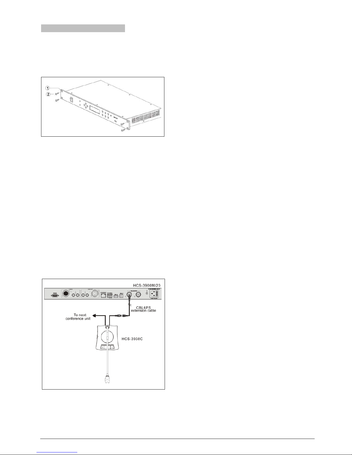
2.1.2 Installation and connection
HCS-3900M/20 series conference main unit is stylish
and cabinet design. Just needs to put the 1U
HCS-3900M/20 main unit into the cabinet, and fix it by
screws. As figure 2.2.
Figure 2.2 Installation
HCS-3900 series CMU has 2 outlet (6P-DIN) trunk-line
cable connectors for contribution units. HCS-3900
series contribution units are equipped with a 6P-DIN
cable with a standard male connector.
When connecting the main unit to the contribution units,
just connect the 6P-DIN male connector of the first unit
to the output of the main unit.
For a longer distance between the contribution unit and
the CMU/EMU, a CBL6PS extension cable is used.
One end of this cable is equipped with a 6P-DIN male
connector; the opposite end is equipped with a 6P-DIN
female connector. Just connect the female connector of
the cable to the conference unit, and connect the male
connector to the output of the main unit.
Figure 2.3 CMU connected to conference units
8
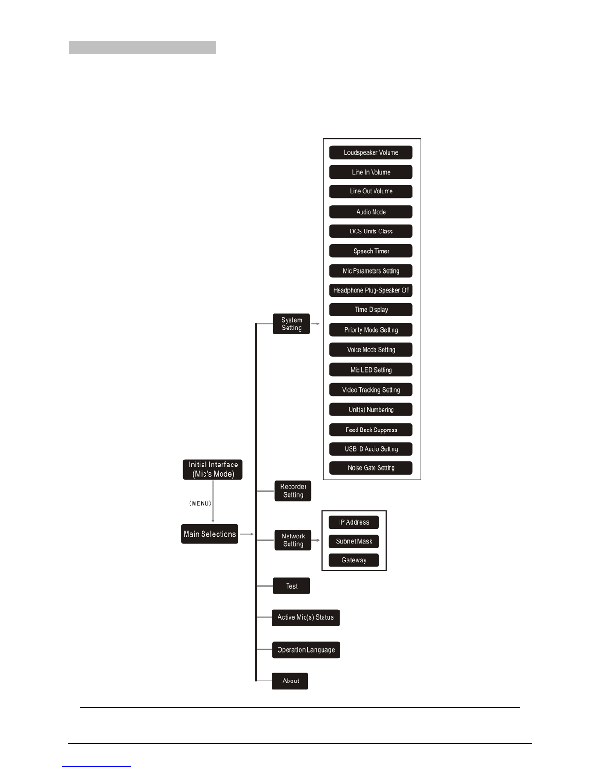
2.1.3 Configuration and operation
After installation and connection and prior to the meeting,
the CMU should be configured through the dialog menu
and the buttons. The term “interface” used hereinafter
means the information displayed on the OLED as the
“user” interface.
The menu structure is shown in the following figure:
Figure 2.4 OLED menu structure of the conference main unit
9
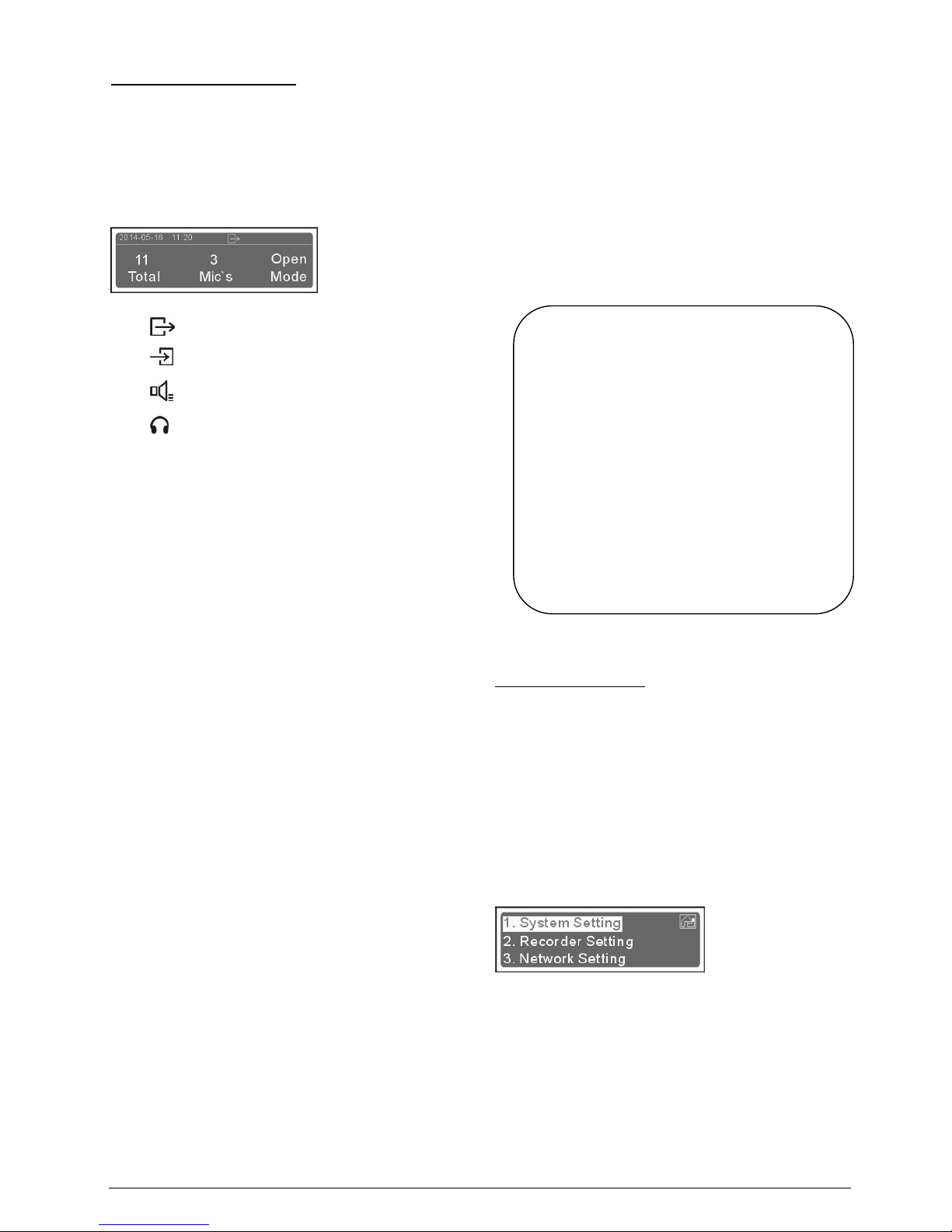
UUUUUUA)Initial interface on OLED
In the initial interface on OLED, there are current time and
the current type of input/output on the top, the system
status information are displayed below which includes:
“Total”
“Mic’s”
“Mode”
1. Type of input/output:
:level of Line In1;
:volume of Line Out1 and Line Out2;
:Master volume;
: volume of monitor headphone.
2. “Total”: Indicates the number of contribution units
being connected to the CMU;
3. “Mic’s”: select the number of maximum active
microphones (1/2/3/4 pcs) by press “” (Up)
button;
4. “Mode”: Display the operation mode (OPEN/
OVERRIDE/VOICE/APPLY/PTT) of the
CMU;
Press the “EXIT” button to choose “OPEN”,
“OVERRIDE”, “VOICE”, “APPLY” or “PTT” from five
different operation modes.
Five operation modes are featured:
“OPEN”: After the number of active microphone(s)
reaches the limit, microphone key control
starts request-to-speak registration. At most
6 microphones can be in the
request-to-speak list. When one of the
activated microphones is turned off, the first
microphone in the list will be automatically
turned on;
“OVERRIDE”: If the limit is achieved, the first activated
microphone will be switched off when
another microphone is turned on. The
maximum number will not exceed the
limit set.
“VOICE”: The microphone is activated by voice. If the
participant speaks into the microphone
closely, the microphone will be switched on
automatically and off after a speech pause
out of predefined time; voice sensitivity level
can be set up;
“APPLY”: Delegate applies to speak by pressing the
microphone On/Off key, the request is
approved or rejected by the chairman unit
with control facility.
“PTT”: When the delegate presses and holds the
microphone ON/OFF button, the microphone
will be activated; when the ON/OFF button is
released, the microphone will be deactivated;
UUUUUUUB)Access main menu
Pressing “Menu” button under initial interface will go to the
main menu, which includes seven menu items:
“System Setting”
“Recorder Setting”
“Network Setting”
“Test”
“Active Mic(s) Status”
“Operation Language”
“About”
The current chosen term (e.g. “System Setting”) is
highlighted.
a). Press the “MENU” button to go to the corresponding
submenu;
b). To switch from term to term use the “/” button;
c). To exit the current menu and to return to the upper
level menu use the “EXIT” button.
Note:
“Voice” speaking mode: t
he chairman unit and
the VIP unit count in the acti
ve microphone
number limitation (1/2/3/4), if the a
ctive
microphone number limitation reached, t
he
microphones of the chairman unit and the
VIP
unit cannot be turned on;
Other speaking mode: t
he chairman unit and
the VIP unit do not count in the active
microphone number limitation (1/2/3/4), a
t
most 6 microphones can be activated at the
same time in a system.
10
 Loading...