


For models T../MA-BTB, T../MA-BTBC and T../MA-ANJ
INSTALLER’S MANUAL
THIS MANUAL IS TO BE LEFT WITH THE OWNER OF THE EQUIPMENT FOR REFERENCE
PURPOSES AND TECHNICAL GUIDANCE. IT IS STRONGLY RECOMMENDED THAT QUALIFIED
DEALER SERVICE PERSONNEL BE CONTACTED IN THE EVENT OF AN UNKNOWN INTERRUPTION
OF SERVICE OR APPARENT PRODUCT MALFUNCTION. AN ANNUAL PREVENTATIVE
MAINTENANCE INSPECTION BY A WATER PROFESSIONAL IS RECOMMENDED TO ENSURE
TROUBLE-FREE AND CONTINUOUS OPERATION.
R1

1
TABLE OF CONTENTS
Preinstallation Instructions for
Dealer
Specifications
Cycle Sequence Settings
Softener System Setup (programming)
Bypass Valve Description & Diagrams
Installation
Installer Settings
Hardness,
Override,
Regen Time & Time of Day
Normal
Operating
& Error Displays, Power
Loss
Low Salt Warning & Resetting It
Start Up Instructions
Replacement
Parts
& Valve Repair
Front Cover, Drive Assembly and Piston
Injector Assembly & Refill Port Assembly
Drain Line 3/4" Assembly & Flow Controls
Drain Line 1" Assembly & Flow Controls
Water Meter & Bypass Valve
Installation Fitting Assemblies & Service Wrench
Control Valve Servicing
Troubleshooting Procedures
PREINSTALLATION
INSTRUCTIONS
This unit has a control valve which enables the setting of not only the length of each regeneration cycle but
also the order in which cycles (steps of regeneration) occur. The following pages instruct how to set the
treatment unit’s sequence of cycles, cycle times, salt dose, exchange capacity, and gallon
capacity/regeneration time. A salt warning option may also be included.
THE DEALER...
1. Read this page, GENERAL INSTRUCTIONS, INSTALLER SETTINGS, NORMAL, OPERATING
DISPLAYS, and LOW SALT WARNING.
2. Complete the CYCLE SEQUENCE SETTINGS.
3. Complete the SOFTENER SYSTEM SETUP.
a. Cycle Times
b. Choose Softener or Filter
c. Set Salt Dose
d. Set Capacity
e. Set How Gallon Capacity Will be Calculated
f. Set Regeneration Time Option
g. Select or Turn Off Low Salt Warning
THE INSTALLER...
1. Read Bypass Valve page.
2. Read GENERAL INSTRUCTIONS, NORMAL OPERATING DISPLAYS, and RESETTING LOW
SALT WARNING (if applicable).
3. Be sure CYCLE SEQUENCE SETTINGS and SOFTENER SYSTEM SETUP are done before leaving for
installation.
4. Follow INSTALLATION INSTRUCTIONS, INSTALLER SETTINGS, TIME OF DAY, and RESETTING
SALT AMOUNT (if applicable).
5. Follow START UP INSTRUCTIONS.

2
CONTROL VALVE SPECIFICATIONS
SERVICE FLOW RATE & PRESSURE
LOSS
(valve only, including bypass valve, but
not including mineral, etc.)
27 gpm (102.2 lpm) @ 15 psi (103 kPa)
ΔP
BACKWASH FLOW RATE &
PRESSURE LOSS
(whole conditioner, including bypass
valve)
27 gpm (102.2 lpm) @ 25 psi (103 kPa)
ΔP
MINIMUM & MAXIMUM OPERATING
PRESSURE
20 psi (138 kPa) – 125 psi (862 kPa)
MINIMUM & MAXIMUM OPERATING
TEMPERATURE
40 °F (4 °C) – 110 °F (38 °C)
CURRENT DRAW & VOLTAGE
0.5 amperes, 110 volts
REGENERANT TANK REFILL RATE
0.5 gpm (1.9 lpm)
INLET/OUTLET FITTING TYPES
(a) 1’’ NPT elbow
(b) ¾’’ & 1’’ PVC solvent weld socket
(c) 1’’ straight brass sweat fitting
(d) ¾’’ straight brass sweat fitting
DISTRIBUTOR TUBE
1.05’’ O.D. (3/4’’ U.S. PVC Pipe Size)
TANK THREAD
2½’’ – 8 NPSM
PC BOARD MEMORY
Nonvolatile EEPROM
(electrically erasable programmable
read only memory)
COMPATIBLE REGENERANTS
Sodium chloride, potassium chloride,
potassium permanganate, sodium
hydroxide, hydrochloric acid
COMPATIBLE CHEMICALS
Sodium bisulfate, sodium hydrosulfite,
chlorine, chloramines
GENERAL INSTRUCTIONS
During operation, the normal user displays such as time of day, capacity remaining before regeneration, flow
rate, and salt warning (optional), are shown. Each of these can be viewed by pressing NEXT to scroll
through them. When moving through any displays or programmings, if no buttons are pressed within five
minutes, the display returns to normal operating displays. Any changes made prior to the five minute time out
are incorporated.
To quickly exit any programming, Installer Settings, etc., press CLOCK. Any changes made prior to the exit
are incorporated.
If desired, two regenerations within 24 hours are possible with a return to the preset program. To do a double
regeneration if the control valve is factory set to “DELAYED REGEN” or “DELAY+IMMEDIATE” (see Step 9S
under SOFTENER SYSTEM SETUP):
1. Press and release the “REGEN” button. The words “REGEN TODAY” will periodically be shown on the
display.
2. Press and hold the “REGEN” button for three seconds until a regeneration begins.
Once the valve has completed the immediate regeneration, the valve will regenerate one more time at the
preset regeneration time.
CYCLE SEQUENCE
CYCLE SEQUENCE instructions allows the setting of the order of the cycle. There are 9 cycles which can be
arranged in any order. Later in this book the INSTALLER SETTINGS allow the setting of how long cycles will
last.
END must be used as the last cycle option. The SERVICE cycle should only be used in brine prefill
applications.
If using upflow brine, verify that the valve is configured as follows:
1. Upflow piston is installed; and
2. Injector is located in up hole and injector plug is in down hole.

3
The following is an example of how to set a valve so that when regeneration is initiated BACKWASH occurs
first, BRINE occurs second, RINSE occurs third, and FILL occurs fourth.
Step 1CS – Press NEXT and DOWN simultaneously for 3 seconds and release. Then
press NEXT and DOWN simultaneously for 3 seconds and release.
Step 2CS – Press NEXT until CYCLE 1 appears. Press UP or DOWN until BACKWASH
shows. Press NEXT to go to Step 3CS. Press REGEN to return to previous step.
Step 3CS – Press UP or DOWN until REGENERANT DRAW DN appears. Press NEXT
to go to Step 4CS. Press REGEN to return to previous step.
Step 4CS – Press UP or DOWN until RINSE appears. Press NEXT to go to Step 5CS.
Press REGEN to return to previous step.
Step 5CS – Press UP or DOWN until FILL appears. Press NEXT to go to Step 6CS.
Press REGEN to return to previous step.
Step 6CS – Press UP or DOWN until END appears. Press NEXT to exit Cycle
Sequence. Press REGEN to return to previous step.
SOFTENER SYSTEM SETUP
In SOFTENER SYSTEM SETUP you choose the time for the cycles selected in CYCLE SEQUENCE and
specifies other operating parameters for the system. The upper and lower limits of the allowable values for
the cycles are as follows:
Cycle Options
Units
Lower/Upper
Limit
BACKWASH
Minutes
1 to 120
RINSE (fast)
Minutes
1 to 120
REGENERANT DRAW DN (combination of brining
and slow rinse)
Minutes
1 to 180
REGENERANT DRAW UP (combination of brining
and slow rinse)
Minutes
1 to 180
FILL
LBS
0.01 to 200
SERVICE
Minutes
1 to 480
Note: Fill is in pounds of salt.
Since no time is associated with the END cycle, the END cycle will not appear in the SOFTENER SYSTEM
SETUP sequence.
4
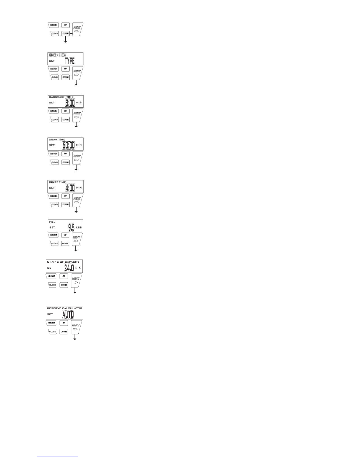
Step 1S – Press NEXT and DOWN simultaneously for 3 seconds and release.
Step 2S – Choose SOFTENING using UP or DOWN. Press NEXT to go to Step 3S. Press
REGEN to exit Softener System Setup.
Step 3S – Select the time for the first cycle (which in this example is BACKWASH) using UP
or DOWN. Press NEXT to go to Step 4S. Press REGEN to return to previous step.
Step 4S – Select the time for the second cycle (which in this example is DRAW) using UP or
DOWN. Press NEXT to go to Step 5S. Press REGEN to return to previous step.
Step 5S – Select the time for the third cycle (which in this example is RINSE) using UP or
DOWN. Press NEXT to go to Step 6S. Press REGEN to return to previous step.
Step 6S – Select the LBS for the fourth cycle (which in this example is FILL) using UP or
DOWN. Press NEXT to go to Step 7S. Press REGEN to return to previous step.
Step 7S – Set Grains Capacity using UP or DOWN. The ion exchange capacity is in grains of
hardness as calcium carbonate for the system based on the pounds of salt that will be used.
Calculate the pounds of salt using the fill time previously selected. Grains capacity is affected
by the fill time. The grains capacity for the selected fill time should be confirmed by testing.
The capacity and hardness levels entered are used to automatically calculate reserve
capacity when capacity is set to AUTO. Press NEXT to go to Step 8S. Press REGEN to
return to previous step.
Step 8S – Set Volume Capacity using UP or DOWN. If valve is set to:
“AUTO” capacity will be automatically calculated and reserve capacity will be
automatically estimated;
“OFF” regeneration will be based solely on the day override set (see Installer Display
Setting Step 3I); or
A number, regeneration initiation will be based off the value specified.
If “OFF” or a number is used, hardness display will not be allowed to be set in Installer
Display Settings Step 2I.
If “OFF” is selected. Regeneration Time is automatically “Delayed”, so Step 9S will not
appear.
See Setting Options Table for more detail. Press NEXT to go to Step 9S. Press REGEN to
return to previous step.

5
Step 9S – Set Regeneration Time Options using UP or DOWN. If value is set to:
“DELAYED REGEN” means regeneration will occur at the preset time;
“IMMEDIATE” means regeneration will occur immediately when the volume capacity
reaches 0 (zero); or
“DELAY+IMMEDIATE” means regeneration will occur at one of the following:
- The preset time when the volume capacity falls below the reserve or the specified
number of days between regenerations is reached whichever comes first; or
- Immediately after 10 minutes of no water usage when the volume capacity
reaches 0 (zero).
See Setting Options Table for more detail. Press NEXT to go to Step 10S. Press REGEN
to return to previous step.
Step 10S – Press NEXT until SALT LEVEL MONITOR appears. Set Salt LEVEL
MONITOR using UP or DOWN. If the value is set to:
“OFF” no low salt level warning will appear for the user.
A specific value, “ALERT” will flash on the display when the calculated remaining
pounds of salt falls below that level.
Press NEXT to exit Softener System Setup. Press REGEN to return to previous step.
This table is to be used as a guide or shortcut to the settings made in Step 3I, 8S, and 9S. For quick
programming, use the recommended setting shown in row 3.

6
BYPASS VALVE
The bypass valve is typically used to isolate the control valve from the plumbing system’s water pressure
in order to perform control valve repairs or maintenance. The 1" full flow bypass valve incorporates four
positions including a diagnostic position that allows a service technician to have pres s u re to test a
system while providing untreated bypass water to the building.
The bypass body and rotors are glass filled Noryl and the nuts and caps are glass filled polypropylene. All
seals are self-lubricating EPDM
to help prevent valve seizing after long periods of non-use. Internal o-rings can easily be replaced if
service is required.
The bypass consists of two interchangeable plug valves that are operated independently by
red arrow shaped handles. The handles identify the direction of flow. The plug valves enable
the bypass valve to operate in four positions.
1. Normal Operation Position: The inlet and outlet handles point in the direction of flow indicated by
the engraved arrows on the control valve. Water flows through the control valve for normal
operation of a water softener or filter. During the regeneration cycle this position provides
regeneration water to the unit, while also providing untreated water to the distribution system.
(See Figure 1)
2. Bypass Position: The inlet and outlet handles point to the center of the bypass.
The system is isolated from the water pressure in the plumbing
system. Untreated water is supplied to the building. (See Figure 2)
3. Diagnostic Position: The inlet handle points toward the control valve and the outlet handle points to
the center of bypass valve.
Untreated supply water is allowed to flow to the system and to the building, while not allowing
water to exit from the system to the building (See Figure 3).
This allows the service technician to draw brine and perform other tests without the test
water going to the building. NOTE: The system must be rinsed before returning the bypass
valve to the normal position.
4. Shut-Off Position: The inlet handle points to the center of the bypass valve and the outlet handle
points away from the control valve. The water is shut off to the building.
The water treatment system will depressurize upon opening a tap in the building. A negative
pressure in the building combined with the softener being in regeneration could cause a siphoning
of brine into the building.
If water is available on the outlet side of the softener or filter it is an indication of water bypassing
the system (i.e. a plumbing cross-connection somewhere in the building). (See Figure 4)

7
INSTALLATION
GENERAL
INSTALLATION
& SERVICE WARNINGS
The control valve, fittings and/or bypass are designed to accommodate minor
plumbing misalignments but are not designed to support the weight of a system
or the plumbing.
Do not use Vaseline, oils, other hydrocarbon lubricants or spray silicone
anywhere. A silicone lubricant may be used on black o-rings, but is not
necessary. Avoid any type of lubricants, including silicone, on red or clear lip
seals.
Do not use pipe dope or other sealants on threads. Teflon tape must be used on the threads of the 1"
NPT elbow, its NPT connection, and on the threads for the drain line connection. Teflon tape is not used on
the nut connections or caps because o-ring seals are used. The nuts and caps are designed to be
unscrewed or tightened by hand or with the special plastic Service Wrench, #V3193. If necessary a pliers
can be used to unscrew the nut or cap. Do not use a pipe wrench to tighten nuts or caps.
Do not place screwdriver in slots on caps and/or tap with a hammer.
SITE
REQUIREMENTS
Water Pressure, 20 – 125 psi (138 – 862
kPa)
Current draw is 0.5 amperes
Water Temperature, 40°– 110° F (4° –
38° C)
A 15 ft power cord is
furnished
The tanks should be on a firm level
surface
The plug-in transformer is
for dry locations only
Electrical: Use a 115/120V, 60Hz
uninterrupted outlet.
Batteries are not used
1. The distance between the drain and the water conditioner should be as short as possible.
2. Since salt must be periodically added to the brine tank, it should be located where it is easily accessible.
3. Do not install any water conditioner with less than 10 feet (3m) of piping between its outlet and the inlet
of a water heater. Water heaters sometimes overheat to the extent that they will transmit heat or
backflow from their inlet back to the water conditioner control. Hot water can severely damage the
conditioner.
Allowing the 10 foot (3m) distance will permit most heat to dissipate before reaching the
water
conditioner. A
more positive way of insuring against backflow is to install a high temperature
check valve. The heater should also have a properly rated tempera- ture and pressure relief valve.
Also, be certain that local codes are not violated.
4. Do not locate unit where it or its connections (including the drain and overflow lines) will ever be
subjected to room temperatures under 34° F (49° C).
5. The use of resin cleaners in an unvented enclosure is not recommended.
SERIAL NUMBER: Record the serial number on the installer’s and customer’s records.
INLET/OUTLET PLUMBING:
Connect to a supply line downstream of outdoor spigots. Install an inlet shutoff
valve and plumb to the unit’s bypass valve inlet located at the right rear as you face the unit. There are a
variety of installation fittings available. They are listed under Installation Fitting Assemblies. When
assembling the installation fitting package (inlet and outlet), connect the fitting to the plumbing system first
and then attach the nut, split ring and o-ring. Heat from soldering or solvent cements may damage the nut,
split ring or o-ring. Solder joints should be cool and solvent cements should be set before installing the nut,
split ring and o-ring. Avoid getting solder flux, primer, and solvent cement on any part of the o-rings, split
rings, bypass valve or control valve. If the building’s electrical system is grounded to the plumbing, install a
copper grounding strap from the inlet to the outlet pipe. Plumbing must be done in accordance with all
applicable local codes.
DRAIN LINE: First, be sure that the drain can handle the backwash rate of the system. Solder joints near
the drain must be done prior to connecting the drain line flow control fitting. Leave at least 6" between the
drain line flow control fittings and solder joints. Failure to do this could cause interior damage to the flow
control. Install a ½" I.D. flexible plastic tube to the Drain Line Assembly or discard the tubing nut and use
the ¾" NPT fitting for rigid pipe. If the backwash rate is greater than 7 gpm, use a ¾" drain line. Where the
drain line is elevated but empties into a drain below the level of the control valve, form a 7" (18 cm) loop at
the discharge end of the line so that the bottom of the loop is level with the drain connection on the control
valve. This will provide an adequate anti-siphon trap. Where the drain empties into an overhead sewer line,
a sink-type trap must be used. Run drain tube to its discharge point in accordance with plumbing code. Pay
 Loading...