


- 1 -

- 2 -
PREFACE
PREFACE
PREFACE
PREFACE
This manual is only a guide to assist you and is not a complete or comprehensive manual of all
aspects of maintaining and repairing your engine. The equipment you have purchased is a complex
piece of machinery .
We
recommend that you consult with a dealer if you have doubts or concerns
as to your expensive or ability to properly maintain or repair your engine.
You
will save time and
the inconvenie nce of having to go back to the store if you choose to write or call us concerning
missing parts, service questions, operating advance, and /or assembly questions. Our air
compressors have the following features:
Air cooled
Four-stroke gasoline internal combustion engine
Recoil starter(Optional electric start)
Large fuel tank
The air-cooled gasoline air compressors are widely used when electrical power is scarce. Air
compressors provide a portable mobile solution in supplying a pneumatic
air
supply for field
operations during project construction.
This manual will explain h ow to operate and service your
air
compressor set.
If you have any questions or suggestions about this manual, please contact your local dealer or us.
Consumers should notice that this manual might differ slightly from the actual product as more
improvements are made to our products. Some of the pictures in this ma n ual may differ slightly
from the actual product as well
.We
reserves the right to make the changes at any time without
notice and without incurring any obligation.

- 3 -
TABLE
TABLE
TABLE
TABLE OF
OF
OF
OF THE
THE
THE
THE CONTENTS
CONTENTS
CONTENTS
CONTENTS
Page
Page
Page
Page number
number
number
number
CHAPTER
CHAPTER
CHAPTER
CHAPTER 1.
1.
1.
1. TECHNICAL
TECHNICAL
TECHNICAL
TECHNICAL SPECIFICATIONS
SPECIFICATIONS
SPECIFICATIONS
SPECIFICATIONS AND
AND
AND
AND
DATA
DATA
DATA
DATA
1
1
1
1
CHAPTER
CHAPTER
CHAPTER
CHAPTER 2.
2.
2.
2. EQUIPMENT
EQUIPMENT
EQUIPMENT
EQUIPMENT DESCRIPTION&KNOWING
DESCRIPTION&KNOWING
DESCRIPTION&KNOWING
DESCRIPTION&KNOWING YOUR
YOUR
YOUR
YOUR
AIR
AIR
AIR
AIR COMPRESSOR
COMPRESSOR
COMPRESSOR
COMPRESSOR
2
2
2
2
CHAPTER
CHAPTER
CHAPTER
CHAPTER 3.
3.
3.
3. SAFETY
SAFETY
SAFETY
SAFETY PRECAUTIONS
PRECAUTIONS
PRECAUTIONS
PRECAUTIONS
3
3
3
3
Prevention
Prevention
Prevention
Prevention from
from
from
from accidental
accidental
accidental
accidental butns
butns
butns
butns
3
3
3
3
Engine
Engine
Engine
Engine safety
safety
safety
safety precautions
precautions
precautions
precautions
3
3
3
3
Air
Air
Air
Air tank
tank
tank
tank safety
safety
safety
safety
4
4
4
4
CHAPTER
CHAPTER
CHAPTER
CHAPTER 4.
4.
4.
4. PREPARATION
PREPARATION
PREPARATION
PREPARATION BEFORE
BEFORE
BEFORE
BEFORE OPERATION
OPERATION
OPERATION
OPERATION
4
4
4
4
Air
Air
Air
Air compressor
compressor
compressor
compressor oil
oil
oil
oil
4
4
4
4
Engine
Engine
Engine
Engine oil
oil
oil
oil
4
4
4
4
F
F
F
F uel
uel
uel
uel
5
5
5
5
A
A
A
A ir
ir
ir
ir cleaner
cleaner
cleaner
cleaner
5
5
5
5
P
P
P
P ressure
ressure
ressure
ressure control
control
control
control valve
valve
valve
valve
5
5
5
5
CHAPTER
CHAPTER
CHAPTER
CHAPTER 5.
5.
5.
5. STARTING
STARTING
STARTING
STARTING THE
THE
THE
THE AIR
AIR
AIR
AIR COMPRESSOR
COMPRESSOR
COMPRESSOR
COMPRESSOR
6
6
6
6
CHAPTER
CHAPTER
CHAPTER
CHAPTER 6.
6.
6.
6. STOPPING
STOPPING
STOPPING
STOPPING THE
THE
THE
THE ENGINE
ENGINE
ENGINE
ENGINE
7
7
7
7
CHAPTER
CHAPTER
CHAPTER
CHAPTER 7.
7.
7.
7. MAINTENANCE
MAINTENANCE
MAINTENANCE
MAINTENANCE
7
7
7
7
Engine
Engine
Engine
Engine oil
oil
oil
oil change
change
change
change
7
7
7
7
A
A
A
A ir
ir
ir
ir filter
filter
filter
filter service
service
service
service
9
9
9
9
Drive
Drive
Drive
Drive belt
belt
belt
belt
9
9
9
9
C
C
C
C leaning
leaning
leaning
leaning the
the
the
the air
air
air
air compressor
compressor
compressor
compressor
10
10
10
10
S
S
S
S ediment
ediment
ediment
ediment cup
cup
cup
cup cleaning
cleaning
cleaning
cleaning
10
10
10
10
S
S
S
S park
park
park
park plug
plug
plug
plug service
service
service
service
10
10
10
10
C
C
C
C arburetor
arburetor
arburetor
arburetor adjustment
adjustment
adjustment
adjustment
11
11
11
11
P
P
P
P utting
utting
utting
utting the
the
the
the air
air
air
air compressor
compressor
compressor
compressor in
in
in
in storage
storage
storage
storage or
or
or
or transporting
transporting
transporting
transporting
11
11
11
11
CHAPTER
CHAPTER
CHAPTER
CHAPTER 8.
8.
8.
8. TROUBLESHOOTING
TROUBLESHOOTING
TROUBLESHOOTING
TROUBLESHOOTING
12
12
12
12
CHAPTER
CHAPTER
CHAPTER
CHAPTER 9.
9.
9.
9.
PART
PART
PART
PART
LISTINGS
LISTINGS
LISTINGS
LISTINGS
1
1
1
1 3
3
3
3

- 2 -
CHAPTER
CHAPTER
CHAPTER
CHAPTER 1.TECHNICAL
1.TECHNICAL
1.TECHNICAL
1.TECHNICAL SPECIFICATION
SPECIFICATION
SPECIFICATION
SPECIFICATION AND
AND
AND
AND
DATA
DATA
DATA
DATA
Technical specifications in S1 units
Technical specifications and date in English units
Item Model
TA011
Compressor
Speed (rpm)
1100
Max. pressure (MPa)
0.8
Air flow rate (m ³ /min)
0.34
Air tank capacity (L)
36
Engine
Engine Model
168F
Type
Air cooled 4-stroke25 included single cylinder
Bore × Store (mm)
68 × 45
Displacement (cc)
163
Speed (rpm)
3600
Max. power output (kw)
4.1
Ignition system
Transistoriz ed ignition (TCI)
Start mode
Recoil manual start
Fuel tank capacity (L)
3.6
Lube-oil capacity (L)
0.6
Dry weight (kg)
82
Dimension (L × W × H)
(mm)
1155 × 455 × 625
Item Model
TA011
Compressor
Speed (rpm)
1100
Max. pressure (PSI)
116
Air flow rate (cfm)
11.9
Air tank capacity (USgal)
9.51
Engine
Engine Model
168F
Type
Air cooled 4-stroke25 included single cylinder
Bore × Store (in.)
2.68 × 1.77
Displacement (cu.in)
9.95
Speed
3600
Max. power output (HP)
5.5
Ignition system
Transistoriz ed ignition (TCI)
Start mode
Recoil manual start
Fuel tank capacity (USgal)
0.95
Lube-oil capacity (OZ.)
20.25
Dry weight (lbs)
181
Dimension (L × W × H)
(in)
45.5 × 17.9 × 24.6

- 3 -
CHAPTER
CHAPTER
CHAPTER
CHAPTER 2.EQUIPMENT
2.EQUIPMENT
2.EQUIPMENT
2.EQUIPMENT DESCRIPTION
DESCRIPTION
DESCRIPTION
DESCRIPTION &
&
&
& KNOWING
KNOWING
KNOWING
KNOWING
YOUR
YOUR
YOUR
YOUR AIR
AIR
AIR
AIR COMPRESSOR
COMPRESSOR
COMPRESSOR
COMPRESSOR
Please read this manual and follow the procedures covered in this manual. Become familiar with
the air compressors functions, applications and limitations.
Below is diagram of the locations of the various controls and functions of the
air
compressor.
WARING: DO NOT exceed the air compressors tank capacity. The tank has a factory preset
pressure release valve. Changing the settings on this valve will void your warranty and we assume
no responsibility for accidents and injuries resulting from user modifications.
Our products are continuously being changed and improved. Every effort has been made to ensure
that information in this manual is accurate and up to date. However, we reserve the right to change,
alter or otherwise improve the product and this manual at a ny time without prior notice.

- 4 -
CHAPTER
CHAPTER
CHAPTER
CHAPTER 3.SAFETY
3.SAFETY
3.SAFETY
3.SAFETY PRECAUTIONS
PRECAUTIONS
PRECAUTIONS
PRECAUTIONS
In order to ensure safety for the consumer, please carefully follow instruction on being careful with
the air compressor.
Never operate the
air
compressor without the belt guard. Failing to do so can lead to serious
injuries as objects may get caught in the belt.
Keep visitors away and never allow children in the work area.
Operate the compressor ONLY outdoors. Never run the compressor indoors as the engine gives off
poisonous carbon monoxide, an odorless and colorless gas. Inhaling carbon monoxide will cause
nausea, fainting or death. Also, keep the
air
compressor at least 3 feet away from flammable matter
for adequate ventilation.
Wear
safety glasses and wear hearing protection when operating the unit.
Always inspect the unit for damage before operating the unit. Inspect the engine for oil leaks or
possible deterioration.
Check all fasteners for proper tightness at frequent intervals.
Do not wear loose clothing or jewelry as it can get caught in the moving mechanical parts of the
air
compressor. Also keep all fingers and other body parts away from the compressor as it may get
caught in the moving mechanical parts.
PREVENTION
PREVENTION
PREVENTION
PREVENTION FROM
FROM
FROM
FROM ACCIDENTAL
ACCIDENTAL
ACCIDENTAL
ACCIDENTAL BURNS
BURNS
BURNS
BURNS
Nevertouch the muffler and its cover when the engine is running. Never touch the muffler and
cover after the engine has been used, as the muffler remains hot for a good period of time.
T he discharge tube from the
air
compressortothe tank gets hot during operation, do not touch the
tube during operation.
ENGINE
ENGINE
ENGINE
ENGINE SAFETY
SAFETY
SAFETY
SAFETY PRECAUTIONS
PRECAUTIONS
PRECAUTIONS
PRECAUTIONS
Do not touch hot surfaces. Allow equipmenttofully cool down before touching.
- 5 -
After the air compressor has been run, the engine produces heat. The temperatures of the muffler
and nearby area can reach or exceed 160 ° F.Severe burns will occur on contact with skin.
Do not modify the
air
compressor in any way. The
air
compressor supplies the rated pressure and
rated airflow at its governed speed.
AIR TANK SAFETY
Do not attempt
to
adjust the safety valve. Also, never attempt
to
repair or modify a tank. The
fabrication involved in modifications of the tank will weaken the tank. Always replace worn,
cracked, or damaged tanks.
Operate the
air
compressor on level surfaces only. Inclined surfaces reduce the effective lubrication
of the engine.
Do not expose the
air
compressortoexcessive moisture, dust, dirt, or corrosive vapors.
CHAPTER
CHAPTER
CHAPTER
CHAPTER 4.PREPARATION
4.PREPARATION
4.PREPARATION
4.PREPARATION BEFORE
BEFORE
BEFORE
BEFORE OPERATION
OPERATION
OPERATION
OPERATION
Before starting the
air
compressor, verify the following conditions.
AIR
AIR
AIR
AIR COMPRESSOR
COMPRESSOR
COMPRESSOR
COMPRESSOR OIL
OIL
OIL
OIL
●
Verify
that
air
compressor head is filled with 10W-30 viscosity oil. Running the
air
compressor without oil will cause severe damage
to
the air compressor head
ENGINE
ENGINE
ENGINE
ENGINE OIL
OIL
OIL
OIL
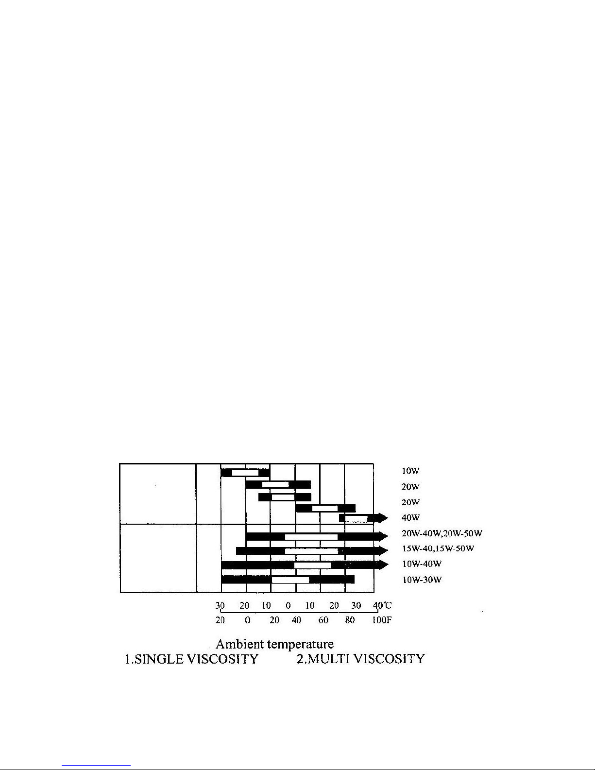
● Fill the engine with SAE 10W-30 engine oil for general use or follow the table below.

- 6 -
● Make sure the
air
compressor is on a level surface and make sure the oil dipstick is on
tight.
FUEL
FUEL
FUEL
FUEL
● Add gasoline and never fill the fuel tank indoors. Also, be sure
to
install the fuel tank cap
on tight after filling.
● DO NOT overfill the fuel tank. Always allow room for fuel expansion.
● Never fill the fuel tank when the engine is running or hot . Allow the unittocool for two
minutes before refueling. DO NOT light a cigarette or smoke when filling the fuel tank.
AIR
AIR
AIR
AIR CLEANER
CLEANER
CLEANER
CLEANER
● Remove the wing nut holding down ● Reinstall the
air
cleaner element
the air cleaner cover and secure the cover by setting
● Remove the
air
cleaner cover and the cover spring
airfilter
● Check the air cleaner element
to
PRESSURE
PRESSURE
PRESSURE
PRESSURE CONTROL
CONTROL
CONTROL
CONTROL
VALVE
VALVE
VALVE
VALVE
be sure they are clean and in
good condition . ● Put the control valve is in the up
position before starting the air
compressor .
● If the
air
filter is
dirty,
remove
and clean the element
● W ash in solvent
● Squeeze
● Soak oil
● Squeeze dry

- 7 -
CHAPTER
CHAPTER
CHAPTER
CHAPTER 5.STARTING
5.STARTING
5.STARTING
5.STARTING THE
THE
THE
THE AIR
AIR
AIR
AIR COMPRSSOR
COMPRSSOR
COMPRSSOR
COMPRSSOR
Turn the fuel valve
to
the ON position Turn the engine switch
to
the ON
p osition. With the recoil starter, pull the
h andle fast.
Move the choke levertothe CLOSED Gradually move the choke lever to
position. OPEN position when the engine
Note: If the engine is warm or the
air
up.
Temperature is high, do not use the choke
Move the throttle control lever slightly
to
Adjust the throttle control lever
the left. until you reach the desired speed.

- 8 -
CHAPTER
CHAPTER
CHAPTER
CHAPTER 6.STOPPING
6.STOPPING
6.STOPPING
6.STOPPING THE
THE
THE
THE ENGINE
ENGINE
ENGINE
ENGINE
I n the event of an emergency, turning the engine switch
to
the “ off ” position can stop the engine.
Under regular conditions, follow these procedures
● Shift the throttle lever fully
to
the right.
● Turn the engine switch
to
the off position.
● Turn the fuel valve
to
the off position.
Note:
Note:
Note:
Note: When
When
When
When operating
operating
operating
operating your
your
your
your engine
engine
engine
engine in
in
in
in high
high
high
high altitudes,
altitudes,
altitudes,
altitudes, the
the
the
the fuel
fuel
fuel
fuel air
air
air
air mixture
mixture
mixture
mixture may
may
may
may be
be
be
be
affected
affected
affected
affected by
by
by
by the
the
the
the high
high
high
high altitude
altitude
altitude
altitude condition.
condition.
condition.
condition. In
In
In
In high
high
high
high altitudes,
altitudes,
altitudes,
altitudes, performance
performance
performance
performance is
is
is
is
decreased
decreased
decreased
decreased and
and
and
and fuel
fuel
fuel
fuel consumption
consumption
consumption
consumption is
is
is
is increased.
increased.
increased.
increased. Please
Please
Please
Please consult
consult
consult
consult with
with
with
with your
your
your
your local
local
local
local
dealer
dealer
dealer
dealer for
for
for
for details
details
details
details on
on
on
on adjusting
adjusting
adjusting
adjusting your
your
your
your engine
engine
engine
engine high
high
high
high altitude
altitude
altitude
altitude conditions.
conditions.
conditions.
conditions.
P ull the recoil handle slowly until pressure is felt by your hand, this means the piston is on the
compression stroke; where the intake and exhaust valves are closed and then let the handle recoil
back into the engine. This natural position will prevent ru st from occurring when the engine is
being stored for long periods of time.
Note: Only perform step 5 when the engine is off. Doing so otherwise will damage the engine.
CHAPTER
CHAPTER
CHAPTER
CHAPTER 7.MAINTENANCE
7.MAINTENANCE
7.MAINTENANCE
7.MAINTENANCE
AIR
AIR
AIR
AIR COMPRESSOR
COMPRESSOR
COMPRESSOR
COMPRESSOR
Check the oil level of both the engine and
air
compressor head daily before operating the
air
compressor.
ENGINE
ENGINE
ENGINE
ENGINE OIL
OIL
OIL
OIL CHANGE
CHANGE
CHANGE
CHANGE
Engine oil is a critical factor in determining the life of your engine. Change the engine oil on time.
Change the engine oil more frequently if the engine is used in dusty areas.
Changing the oil while the engine is still warm will yield best results for the engine.
When the oil is still warm, you get rapid and complete draining of the oil.
Oil change procedures
1. Remove the oil filler cap and drain plug
to
drain the oil.
2. Install the drain plug, and tighten it securely.

- 9 -
3. Refill with the recommended oil and check the oil level.
4. Install the oil filler cap.
The engine oil capacity is .60 liters or .16 gallons.
The gear oil capacity of the 1/2 reduction is .50 liters or .13 gallons.
The gear oil capacity of the 1/6 reduction is .15 liters or .03 gallons.
Note: Do not touch motor oil for long periods of time. Used motor can cause skin cancer if it comes
in contact with the skin for prolonged periods of time. Getting cancer from used motor oil is
unlikely unless you handle used motor oil on a day basis.
To
be safe always wash your hands
thoroughly with soap and water as soon as possible after handing used oil.
Below a maintenance schedule.
REGULAR SERVICE PERIOD
Performed at every indicated
month or operating hour interval,
whichever comes first
Each use
First
month
or
20 Hrs.
Every
3 month
or
50 Hrs.
Every
6 month
or
100 Hrs.
Every
year
or
300 Hrs.
ITEM
Engine oil
C heck level
0
C hange00
Reduction gear oil
(applicable model only)
C heck level
0
C hange
0
Air cleaner
C heck level
0
C lean
0 (1)
Sediment cup
Clean
0
Spark plug
Check-clean
0
Spark arrester
(optional part)
Clean
0
Valve
clearance
Check-Adjust
0 (2)
Fuel tank and strainer
Clean
0 (2)
Fuel line
Check
(Replace if necessary)
Every 2 year (2)

- 10 -
AIR
AIR
AIR
AIR FILTER
FILTER
FILTER
FILTER SERVICE
SERVICE
SERVICE
SERVICE
A
dirty or clogged air filter will prevent
air
fro, flowing freely in
to
the carburetor assembly. Always
keep the air filter clean or replace if necessary. Also, if the
air
filter is dirty or clogged, the
performance of the engine goes down. If operating the engine in a dusty area, service the
air
filter
more frequently as dust particles will clog the filter at a faster rate. Never run the engine without an
air
filter, dust particles may get into the intake system and damage the engine. Rapid engine wear
will occur if the engine is run without the
air
filter.
Do not w a sh the airfilter if it is the paper type. Also, never use the gasoline
to
wash
air
filter
elements because gasoline is highly flammable and dangerous.Afire or explosion could occur.
Instructions on changing the
air
filter
● Take the wing nut off and remove the
air
filter cover. Remove the elements and separate
them. Check the elements for tears and holes. If holes or tears are present, replace the
air
filter elements.
● The foam element can be washer. W arm water and household detergent will work fine
for washing the foam filter element. After washing, rinse it thoroughly with water and
allow the elementtodry. Soak the element in clean engine oil and squeeze the oil out. If
these is too much oil left in foam element, the engine will smoke during startup
●
Tap
lightly several times on a hand surface
to
remove excess dirt from the paper filter.
Never brush on the paper clement as this just forces more dirt into the paper element. Use
compressed airtoblow from the inside ourtoremove the excess dirt.
DRIVEBELT
DRIVEBELT
DRIVEBELT
DRIVEBELT
Belts will stretch in normal use.Aproperly adjusted belt will deflect 1/2 inch with a 5 pound force.
To
adjust the belt tension, follow the procedures below.
● Remove the belt guard
● Loosen the four fasteners holding the engine
to
the base-plate.
● Shift the engine in the proper direction so that the desired tension is achieved.
● Align the belt and pulleys before tightening down the engine.

- 11 -
CLEANING
CLEANING
CLEANING
CLEANING THE
THE
THE
THE AIR
AIR
AIR
AIR COMPRESSOR
COMPRESSOR
COMPRESSOR
COMPRESSOR
Air compressor maintenance consists of keeping the unit clean and dry. Be sure
to
store the unit in a
clean and dry environment, where it will not be exposed
to
excessive dust, dirt, moisture or any
corrosive vapors. Cooling slots should always be clean and free from clogs.
Note: Do not use a garden hose
to
clean the air compressor.
Water
can enter the fuel and intake
system and cause problems.
●
To
cle a n the air compressor, use a damp cloth
to
wipe the exterior surface.
● Use a soft bristle brush
to
loosen caked on dirt of oil .
● Use a vacuum cleanertopick up loose dirt and debris.
● Compressed air (nottoexceed 25psi) may be used
to
blow away dirt.
SEDIMENT
SEDIMENT
SEDIMENT
SEDIMENT CUP
CUP
CUP
CUP CLEANING
CLEANING
CLEANING
CLEANING
Turn the fuel valve off a nd remove the sediment cup with the O-ring. Wash them thoroughly in
non-flammable solvent. Dry them thoroughly and reinstall them tightly. Turn the fuel valve ON
and look for leaks.
Note: Try nottospill fuel, if the fuel is spilled, clean the area first before starting the engine. The
engine will create a spark when started, so if there is fuel around, it may ignite the fuel causing a
serious fire or explosion.
SPARK
SPARK
SPARK
SPARK PLUG
PLUG
PLUG
PLUG SERVICE
SERVICE
SERVICE
SERVICE
● Remove the wire from the spark plug.
● Use a deep socket or spark plug sockettoremove the spark plug.
● Check for mechanical damage and or carbon buildup.
● If the spark plug is fouled, replace spark plug with new one.
● Spark plugs may come pre gapped, if not an ordinary gap of. 7mm or.028 inches would
do just fine.Tofix a gap, bead the side of the electrode with a spark plug gapping tool.
Note: Make sure the replacement spark plug is in the correct heat range. An incorrect heat range
spark plug can damage your engine. Also, never tough the muffler during or after the engine has
been run.
● Make sure the spark plug washer is in good condition or brand-new.
● Threat the spark plug in by hand first before using a tool. This will prevent stripping the
threads on the cylinder head assembly and the spark plug.

- 12 -
● After the spark plug has seated, tighte n the spark plug with a spark plug wrench
to
compress the washer.
Note: For new spark plugs, tighten an extra1/2 turn after the spark plugs seats
to
compress the
washer. If installing a used spark plug; tighten 1/8-1/2 turn. The spark plug must be securely
tightened, or the spark plug can become very hot and damage the engine.
CARBURETOR
CARBURETOR
CARBURETOR
CARBURETOR ADJUSTMENT
ADJUSTMENT
ADJUSTMENT
ADJUSTMENT
● Start the engine and allow ittowarm up.
● While the engine is idling, turn the pilot screw in or outtothe setting that produces the
highest speed.
Note: Be careful nottotighten the pilot screw against its seat. Tightening the pilot screw against its
seat will damage the seat.
● When the pilot screw is adjusted correctly, turn the throttle stop screw
to
achieve the
standard idle speed; which is about 1,400 100rpm.
PUTTING
PUTTING
PUTTING
PUTTING THE
THE
THE
THE AIR
AIR
AIR
AIR COMPRESSOR
COMPRESSOR
COMPRESSOR
COMPRESSOR IN
IN
IN
IN STORAGE
STORAGE
STORAGE
STORAGE OR
OR
OR
OR
TRANSPORTING
TRANSPORTING
TRANSPORTING
TRANSPORTING
Please follow these instructions before storing your engine.
● Clean the storage area.
● Drain the fuel into a suitable container.
● Remove the sediment cup and clean thoroughly
● Replace the sediment cup and tighten securely.
● Drain the fuel from the carburetor by loosening the dialing scram. Drain the fuel into a
suitable container.
Note: Do not smoke near gasoline. Also do not allow flames or sparks near gasoline because
gasoline is extremely flammable.
● Chang the engine oil while engine is still warm.
● Take the spark plug out and put some oil into the combustion chamber. Then use the recoil
starter and crank the engine a few times
to
mix the oil around in the chamber. Put the spark
plug back on being careful nottostrip the threads.
● Pull the starter rope until resistance is felt. This is when the intake and exhaust valves are
closed and the piston is on the piston is on the compression stroke.

- 13 -
CHAPTER
CHAPTER
CHAPTER
CHAPTER 8.TROUBLESHOOTING
8.TROUBLESHOOTING
8.TROUBLESHOOTING
8.TROUBLESHOOTING
Symptom
Probable cause
Corrective Action
Low discharge
pressure
1.
Air demand exceeds pump
capacity.
2.
Leaking air
3.
Restricted
air
intake
4.
Blown gaskets
5.
Leaking or damaged valves
1.
Decrease
air
demand or use a larger
capacity
air
compressor
2.
Listen for high pitched escaping air.
Apply soap solution to all fittings and
connections. Bubbles will appear at
points of leakage. Tighten or replace
leaking fittings or connections.
3.
Clean
air
filter element.
4.
Replace faulty gaskets.
5.
Remove head and inspect for valve
breakage, misaligned valves,
damaged valve seats, etc. Replace
defective parts and reassemble.
Pump
overheating and
damaging air
filter.
1.
Insulating gasket between filter
and head is missing.
2.
Brolen valves blown gasket.
1.
Install gasket.
2.
Replace valves or install new gaskets.
Excessive noise
or abnormal
noise
1.
Loose motor or losse pulley.
2.
Low oil in crankcase
3.
Worn connecting rods
4.
Worn piston pin
5.
Piston hitting valve plate
6.
Noisy check valve.
1.
Tighten engine mount bolts and
pulley setscrews.
2.
Refill oil to the proper level. Also, if
always
low,
check for possible
damage to bearings or oil leaks.
3.
Replace connecting rod. Maintain oil
level and change oil more frequently.
4.
Remove old piston pin, measure abd
verify specifications are within limits.
If not, replace piston pin and replace
oil more frequently.
5.
Remove the compressor head and
valve plate for carbon deposits or
other foreign objects. Replace the
head and valve plate and use a new
gasket.
6.
Replace.

- 14 -
Note: Please refer to the engine owner’s manual for troubleshooting with the engine.
Large quantities
of oil in air
supply
1.
Worn piston rings.
2.
Air intake clogged
3.
Oil level in compressor head to
high
4.
Wrong oil viscosity
1.
Replace with new rings.
2.
Clean
air
filter
3.
Drain some of the oil.
4.
Use 10W - 30
Water in
D ischarge air.
1.
Water
increases with humid
weather
1. Drain tank daily.
2. Add a filter to reduce the amount of
water in the air line
Tank does not
hold pressure
when compressors
off and shut off
valve is closed.
1.
Worn check valve
2.
Check all connections and
fittings for leaks.
3.
Check tank for cracks or pin
hoies.
1.
Repiace check valve
2.
Tighten
3.
Repiace tank. Never repair a
damaged tank.
Excessive
vibration
1.
Loose fasteners
2.
Belt need replacement.
3.
Belt alignment
1.
Tighten
2.
Replace with correct size
3.
Align engine and air compressor
pulleys.
Pressure switch
continuously
blows air out the
unloader valve
1. Malfunctioning check valve
1. replace the check valve if the unloader
valve bleeds off constantly
- 15 -
CHAPTER
CHAPTER
CHAPTER
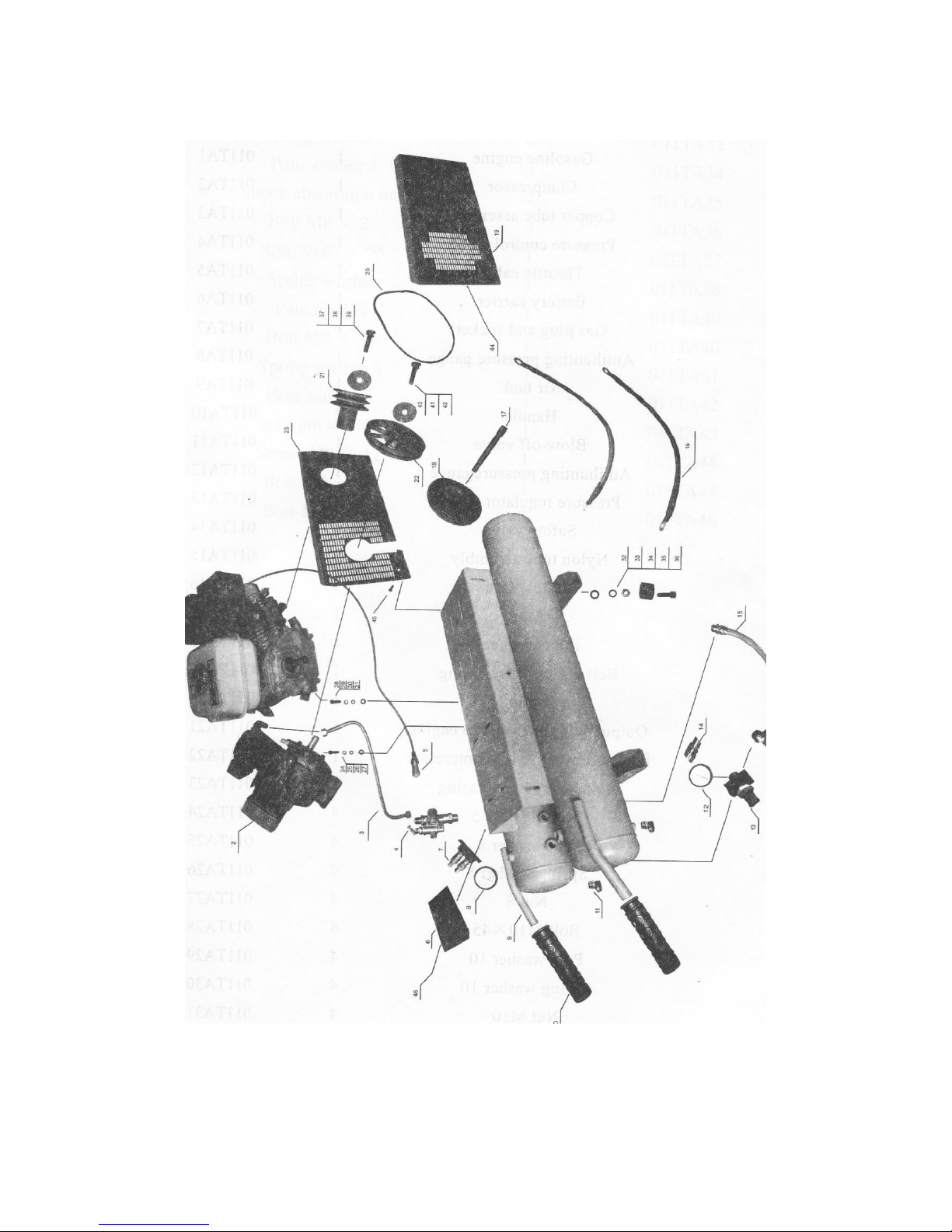
CHAPTER 9.PART
9.PART
9.PART
9.PART LISTINGS
LISTINGS
LISTINGS
LISTINGS

- 16 -
Number
Number
Number
Number
Part
Part
Part
Part Description
Description
Description
Description
Qty
Qty
Qty
Qty
Part
Part
Part
Part Number
Number
Number
Number
1
Gasoline engine
1
011TA1
2
Compressor1011TA2
3
Copper tube assembly
1
011TA3
4
Pressure control
Valve
1
011TA4
5
Throttle cable1011TA5
6
Battery carrier
1
011TA6
7
Gas plug and socket
1
011TA7
8
Antihunting pressure guage
1
011TA8
9
Air tank1011TA9
10
Handle1011TA10
11
Blow-off valve
1
011TA11
12
Antihunting pressure gauge
1
011TA12
13
Pressure regulator
Valve
1
011TA13
14
Safety
Valve1011TA14
15
Nylon tube assembly
1
011TA15
16
Battery line2011TA16
17
Axle1011TA17
18
Rubber wheel
1
011TA18
19
Belt pulley outer casing
1
011TA19
20
Strap1011TA20
21
Output belt pully of the engine
1
011TA21
22
Belt pulley of the air compressor
1
011TA22
23
Belt pulley inner casing
1
011TA23
24
Bolt M8 × 33.54011TA24
25
Pain washer 84011TA25
26
Spring washer 8
4
011TA26
27
Nut 84011TA27
28
Bolt M10 × 454011TA28
29
Pain washer 10
4
011TA29
30
Spring washer 10
4
011TA30
31
Nut 104011TA31
32
Acorn nut 184011TA32

- 17 -
Number
Number
Number
Number
Part
Part
Part
Part Description
Description
Description
Description
Qty
Qty
Qty
Qty
Part
Part
Part
Part Number
Number
Number
Number
33
Spring washer 8
4
011TA33
34
Pain washer 84011TA34
35
Shock absorption mat
4
011TA35
36
Bolt M8 × 254011TA36
37
Bolt 7/16 ”× 25
1
011TA37
38
Spring washer
1
011TA38
39
Pain washer1011TA39
40
Bolt M8 × 351011TA40
41
Spring washer 8
1
011TA41
42
Pain washer 81011TA42
43
Split pin 4 × 35
1
011TA43
44
Screw M8 × 121011TA44
45
Bolt M8 × 201011TA45
46
Bolt M8 × 121011TA46
 Loading...