


USER MANUAL
G.shdsl+ modem with built-in router
TAHOE 681 / 682
FREEDOM OF COMMUNICATION


TABLE OF CONTENTS
1. Introduction ........................................................................ 1
2. Interfaces ........................................................................... 3
3. Modem configuration using built-in keyboard and LCD.5
4. Configuration using telnet or serial console .................... 10
4.1. Telnet connection ............................................................. 10
4.2. Serial console ................................................................. 10
4.3. Commands ...................................................................... 11
5. Technical data .................................................................... 29
6. Declaration of Conformity ................................................. 30
i

®
Tahoe 681/682 (G.shdsl+ / Ethernet 10/100Base-T modem)
User Manual
http://www.tahoe-group.com/
Firmware version 1.2.6
Other trademarks of other companies are used only for explanation and to
®
Tahoe assumes no responsibility for any errors or omissions that may appear in
this document. Tahoe makes no commitment to update the information
contained here, and may make changes at any time without notice.
©2004 Tahoe . All rights reserved.
the owner's benefit, without intent to infringe.
®
®
ii

1
1. Introduction
Thank you for purchasing the Tahoe 681/682 modem. We did our
best to ensure highest reliability and performance of our products.
Devoting many years of research and development we are proud to
provide a superior quality device unfolding new possibilities for the use of
the copper lines.
®
Tahoe 680 series modems are G.shdsl+ modems allowing data
transmission with speeds up to 4864 kbps on 2-wire line or up to 9728
kbps on 4-wire line. Thanks to powerful TCPAM-32 modulation
throughputs are much higher than using HDSL technique and reach is
nearly twice that of VDSL. Adding low cost of deployment, Tahoe
modems become an interesting alternative even for fiber optic
connections.
The modem exists in two versions:
¡ Tahoe 681 - up to 4864 kbps on 2-wire line
¡ Tahoe 682 - up to 9728 kbps on 4-wire line, traffic is
®
®
automatically divided between two lines, fall back to 2-wire mode
is done automatically in case o line failure
The modem has a built-in TCP/IP router and an Ethernet
10/100Base-T interface allowing connection directly to a LAN. Router
software supports IP, ARP, TCP, UDP and ICMP protocols. It is
manageable using telnet, SNMP, serial console or built-in LCD and
keyboard. Traffic statistics are available through WWW. Modem status
messages can be sent to a central server using syslog protocol.
One network interface may support more than one IP subnetwork
thanks to interface aliases (eth0:0, eth0:1, etc.) and VLAN interfaces
(eth0.1, eth0.2, etc.). Modem may also work as a bridge - in this mode
both interconnected networks create one whole on the hardware level
(e.g. computers with Microsoft Windows™ operating system will see
®
each other in the network neighborhood).
A built-in DHCP/BOOTP server allows assigning of IP addresses,
network mask, router addresses and other parameters to the network
stations. DHCP/BOOTP Relay Agent listens for DHCP and BOOTP
requests and forwards them to a central server.
Modem supports Network Address Translation, i.e. makes it
possible for a whole network to access Internet using only one real IP
address. Additional firewall improves the network security by blocking
1

unwanted traffic basing on IP addresses, TCP or UDP ports and protocols
appearing in the received packets.
The system firmware is stored in the Flash memory - it is possible
to update it using the TFTP protocol. The configuration is stored in the
EEPROM memory.
2

2
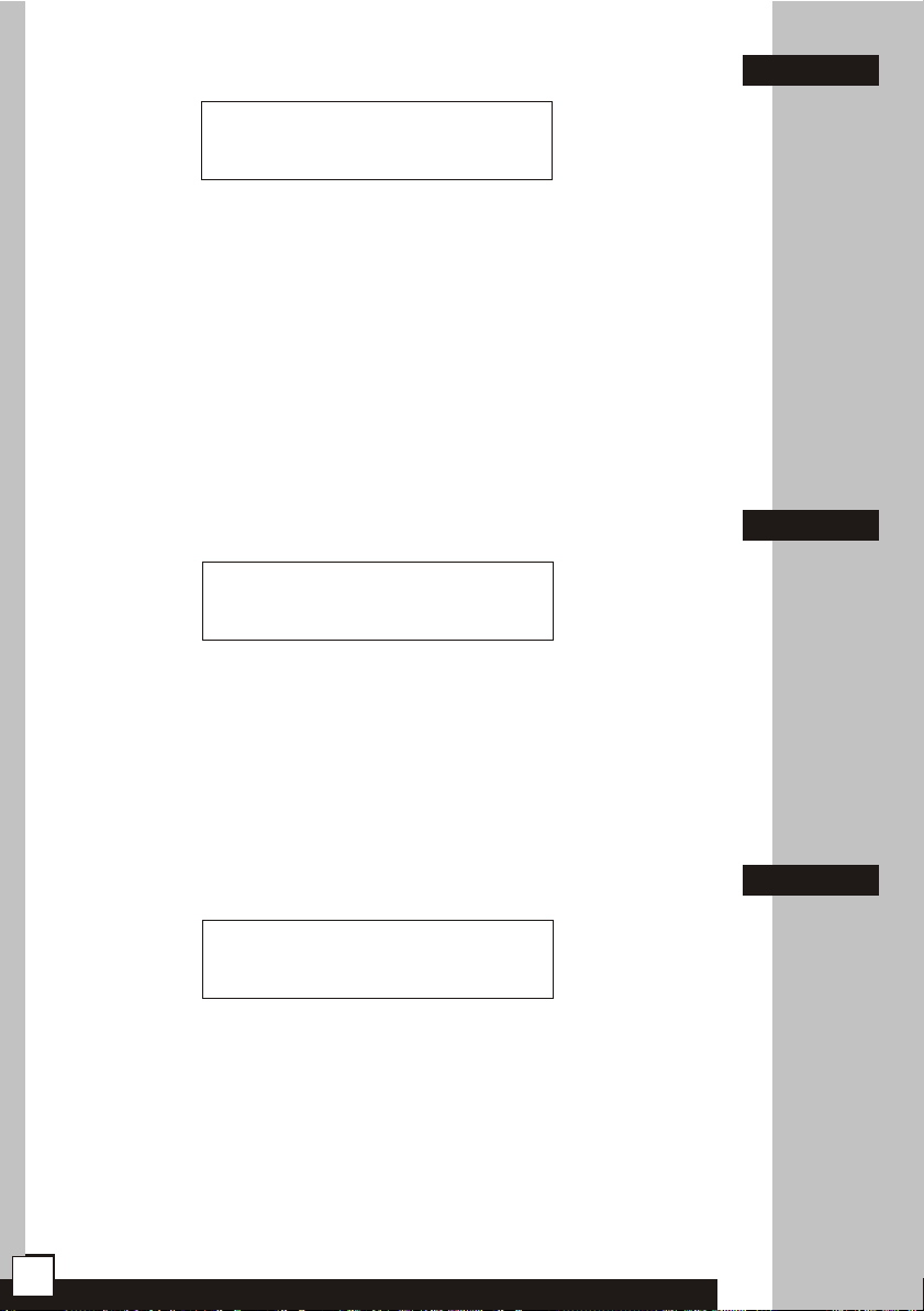
2. Interfaces
Following connectors are found on the rear panel of the modem:
2.1
G.shdsl
serial
console
LAN
(FastEthernet)
power
connector
power
switch
I
O
2.1. G.shdsl
It is a 6-pin RJ-11 connector used to connect the leased line. In
Tahoe 681 the line should be connected to pins 3 and 4. In case of Tahoe
682 one line should be connected to pins 2 and 3, while the other one - to
pins 4 and 5. The first and second line may be interchanged between
modems - that will be automatically detected. The polarization of a line is
not important.
Pin Tahoe 681
1
2
3
4
5
6
-
line 1
line 1
-
-
Tahoe 682
line 1
line 1
line 2
line 2
-
2.2
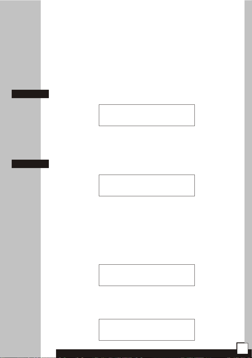
2.2. Serial console
The RS-232 serial console is used for modem management. It has
a DB9/M connector and works as a DTE, i.e. a null-modem cable should
be used to connect it to a PC. Three lines (bolded) are sufficient. Terminal
settings are 9600 bps, 8 data bits, 1 stop bit, no parity, no handshaking.
Pin Name
1
2
3
4
5
6
7 RTS
8 CTS
9 RI
DCD
RXD
TXD
DTR
GND
DSR
carrier detect, transmission readiness signaling
data received from the PC
data sent by the modem to the PC
active, when the PC is switched on
signal ground
active, when the modem is switched on
used by the PC to inform that is has data to send
used by the modem to permit data transmission
ring indicator (signal used in telephone modems)
Description
3

After connecting the console to the PC and running a terminal
software, user has the same access to the modem functions, as through
a telnet connection (see chapter 4).
2.3. FastEthernet
The FastEthernet interface is used to connect the modem to the
Local Area Network. It may work at speeds of 10 Mbps (10Base-T) or 100
Mbps (100Base-T), in either full-duplex or half-duplex mode. The mode
of transmission is selected automatically.
Modem should be connected to a Ethernet switch or a hub using a
straight patch-cord or to a PC, a router or an uplink port in a switch using
a crossed-over one. After connecting a LED named “LAN Link” should be
lit.
In the Tahoe 681/682 modems the FastEthernet interface has
®
following status LEDs:
¡ LAN Link - lit, when modem is connected to a LAN
¡ LAN Act - LAN activity, blinks when data is sent or received
¡ 10/100M - LAN connection throughput - lit, when 100 Mbps
connection speed is negotiated
On the right two WAN status LEDs are present, blinking when data
is, respectively, received from or sent to the DSL line:
¡ WAN Rx- WAN Receive
¡ WAN Tx - WAN Transmit
2.3
4

3
3. Modem configuration using built-in
keyboard and LCD
The easiest way to configure a modem is to use the four-button
keyboard and the LCD. After switching the power on, an information
about the modem type, the line throughput and state will be displayed.
The messages are different for Tahoe 681 and Tahoe 682 modems:
Tahoe 681
4864 kb/s BOOT
Tahoe 682 BOOT
9728 kb/s BOOT
Four-letter code on the right describes the DSL line state:
¡ BOOT - booting of the G.shdsl transceiver
¡ IDLE - transceiver inactive
¡ DOWN - transceiver active, line not synchronized
¡ SYNC - line synchronized, data may be transmitted
In case of Tahoe 682 modem, the top code describes the first
line, while the bottom - the second one.
On the right of the display there is a keyboard with “up”, “down”,
“Escape” and “Enter” keys. By pressing up/down buttons you may
browse the configuration menu:
¡ speed setting
¡ modem type setting (Master/Slave)
¡ line modulation selection
¡ storing settings in the EEPROM memory
¡ setting the IP address and network mask on the eth0 interface
¡ selection of the language
¡ connection reset
¡ modem reset
¡ bridge mode toggling
Each pressing of the “Escape” button causes the return to the
primary display with modem type and state. Pressing of the “Enter”
button selects given menu option.
5
3.1. Throughput setting
Line rate:
9728 kb/s
After pressing Enter the throughput may be set using up/down
buttons. In Tahoe 681 modem it may be chosen from 64-4864 kbps
range with 64 kbps step, while in Tahoe 682 - from 128-9728 kbps
range with 128 kbps step. In the latter case the actual throughput of
each line is half of the throughput set. Different rates for each line may
be set using the serial console or the telnet connection (see chapter 4).
After choosing the right speed and pressing Enter modem will
reset the connection and renegotiate it with new settings.
NOTE: The same throughput must be set on both modems.
3.1
3.2. Modem type
Modem type:
Master / HTU-C
After pressing Enter the modem type may be selected - either
Master (HTU-C) or Slave (HTU-R). After selecting the type and pressing
Enter again the connection will be reset and renegotiated with new
settings.
NOTE: Always one modem has to be set as a Master and the
other one as a Slave.
3.3. Line coding
Line coding:
32-TCPAM
After pressing Enter the G.shdsl line coding (signal modulation)
may be chosen. The number (32 in the example above) means the
number of values encoded in one symbol (32 - 5 bits per symbol). The
higher this number is, the lower is the signal frequency, which gives
better immunity for signal attenuation and higher reach.
3.2
3.3
The second part - PAM or TCPAM - means either the Pulse
Amplitude Modulation or Trellis Coded Pulse Amplitude Modulation.
6
The latter is more efficient.
It is recommended to use the 32-TCPAM modulation, which
provides the best results. The remaining line codings are available to
provide compatibility with others’ manufacturers equipment. Moreover
32-TCPAM allows throughputs from 256 kbps to 4864 kbps per line,
while 16-TCPAM - from 64 kbps to 2304 kbps.
The “Auto” setting forces use of 32-TCPAM for speeds higher
than or equal to 256 kbps per line and 16-TCPAM for lower rates.
3.4
3.5
3.4. Write configuration to EEPROM
Write config
to EEPROM
Every change to the configuration will be lost after reboot or
power off unless the settings are written to the EEPROM. After reaching
this option just press Enter to save them.
3.5. IP address and network mask on eth0 interface
IP address and
netmask on eth0
As a factory default the Ethernet interface of the modem has the
IP address set to 10.0.0.1 and the network mask to 255.0.0.0. After
connecting to this address using telnet further configuration can be
done. The IP address may be changed, however, using the keyboard.
It’s useful when the IP address has been changed and then forgotten.
After pressing Enter, up and down buttons may be used to
change the first octet of the IP address:
Set IP address:
10._._._
Then after pressing Enter second, third and fourth octet may be
set. Afterwards the network mask may be changed. Up and down keys
lengthen or shorten it, respectively, by one bit:
Set netmask:
255.0.0.0
7
 Loading...