


V.35 / Ethernet Routers series
TAHOE 1800
FREEDOM OF COMMUNICATION
USER MANUAL


i
TABLE OF CONTENTS
1. Introduction ........................................................................ 1
2. Interfaces ........................................................................... 2
3. Configuration and management ...................................... 5
4. Technical data ................................................................... 23
5. Declaration of Conformity ................................................ 25

ii
®
Tahoe 1800 series (V.35 / Ethernet routers)
User Manual
http://www.tahoe-group.com/
Firmware version 1.2.7
®
©2004 Tahoe . All rights reserved.
Other trademarks of other companies are used only for explanation and to
the owner's benefit, without intent to infringe.
®
Tahoe assumes no responsibility for any errors or omissions that may appear in
®
this document. Tahoe makes no commitment to update the information
contained here, and may make changes at any time without notice.

1
1
1. Introduction
®
Tahoe 1800 series V.35/Ethernet routers are available in two
versions:
®
¡ Tahoe 1801 router contains one V.35 port and one Ethernet
port
®
¡ Tahoe 1808 router also contains one V.35 port, but instead of a
single Ethernet port, a managed 8-port VLAN-enabled switch is
built in
Routers are destined for use with HDLC or synchronous PPP point-
to-point connections and Frame Relay networks.
Router software supports IP, ARP, TCP, UDP and ICMP protocols. It
is manageable using telnet, SNMP or serial console. Traffic statistics are
available through WWW. Router status messages can be sent to a central
server using syslog protocol.
One network interface may support more than one IP subnetwork
thanks to interface aliases (eth0:0, eth0:1, etc.) and VLAN interfaces
(eth0.1, eth0.2, etc.). Router may also work as a bridge - in this mode
both interconnected networks create one whole on the hardware level
®
(e.g. computers with Microsoft Windows™ operating system will see
each other in the network neighborhood).
A built-in DHCP/BOOTP server allows assigning of IP addresses,
network mask, router addresses and other parameters to the network
stations. DHCP/BOOTP Relay Agent listens for DHCP and BOOTP
requests and forwards them to a central server.
Routers support Network Address Translation, i.e. make it
possible for a whole network to access Internet using only one real IP
address. Additional firewall improves the network security by blocking
unwanted traffic basing on IP addresses, TCP or UDP ports and protocols
appearing in the received packets.
The system firmware is stored in the Flash memory - it is possible
to update it using the TFTP protocol. The configuration is stored in the
EEPROM memory.

2 3
2. Interfaces
2.1. V.35
The V.35 interface is equipped with DB-25 connector. A V.35 cable
terminated with 34-pin male (DTE) Winchester connector should be
connected here, so the router could be connected to a DCE device, like a
V.35 modem.
2.2. Ethernet
The Ethernet interface is used to connect the router to the Local
®
Area Network. In case of Tahoe 1801 router it is a single RJ-45
connector with four LEDs:
¡ LNK - LAN Link, signals a proper connection to the LAN
¡ COL - Collision, signals an attempt to transmit to the LAN while
another device also sends data
¡ LRX - LAN Receive, flashes, when data is received from the LAN
¡ LTX - LAN Transmit, flashes, when data is transmitted to the LAN
A router should be connected to an Ethernet switch or a hub using
a straight patch-cord or to a PC, another router or an uplink port in a
switch using a crossed-over one. After connecting a LED named “LAN
Link” should be lit.
®
In case of Tahoe 1808 router an 8-port switch is available
instead of a single Ethernet interface. Each switch port has three LEDs
associated to it:
¡ 10/100Mbps - when lit, signals a 100Mbps connection
¡ LINK/ACTIVITY - when lit signals a proper connection to the
other device, flashes while transmitting or receiving data
¡ DUPLEX/COLLISION - when lit signals a full-duplex
connection, flashes when a collision occurs in a half-duplex
connection
The switch can be managed through a telnet or console
connection. It supports VLAN tagging and automatically detects a
crossed-over cable (so-called MDIX function).
2.3. Serial console
The RS-232 serial console is used for router management. It has a
DB9/M connector and works as a DTE, i.e. a null-modem cable should be
used to connect it to a PC. Three lines (bolded) are sufficient. Terminal
2.1
2
2.2
2.3
4
settings are 9600 bps, 8 data bits, 1 stop bit, no parity, no handshaking.
After connecting the console to the PC and running a terminal
software, user has the same access to the router functions, as through a
telnet connection (see chapter 3).
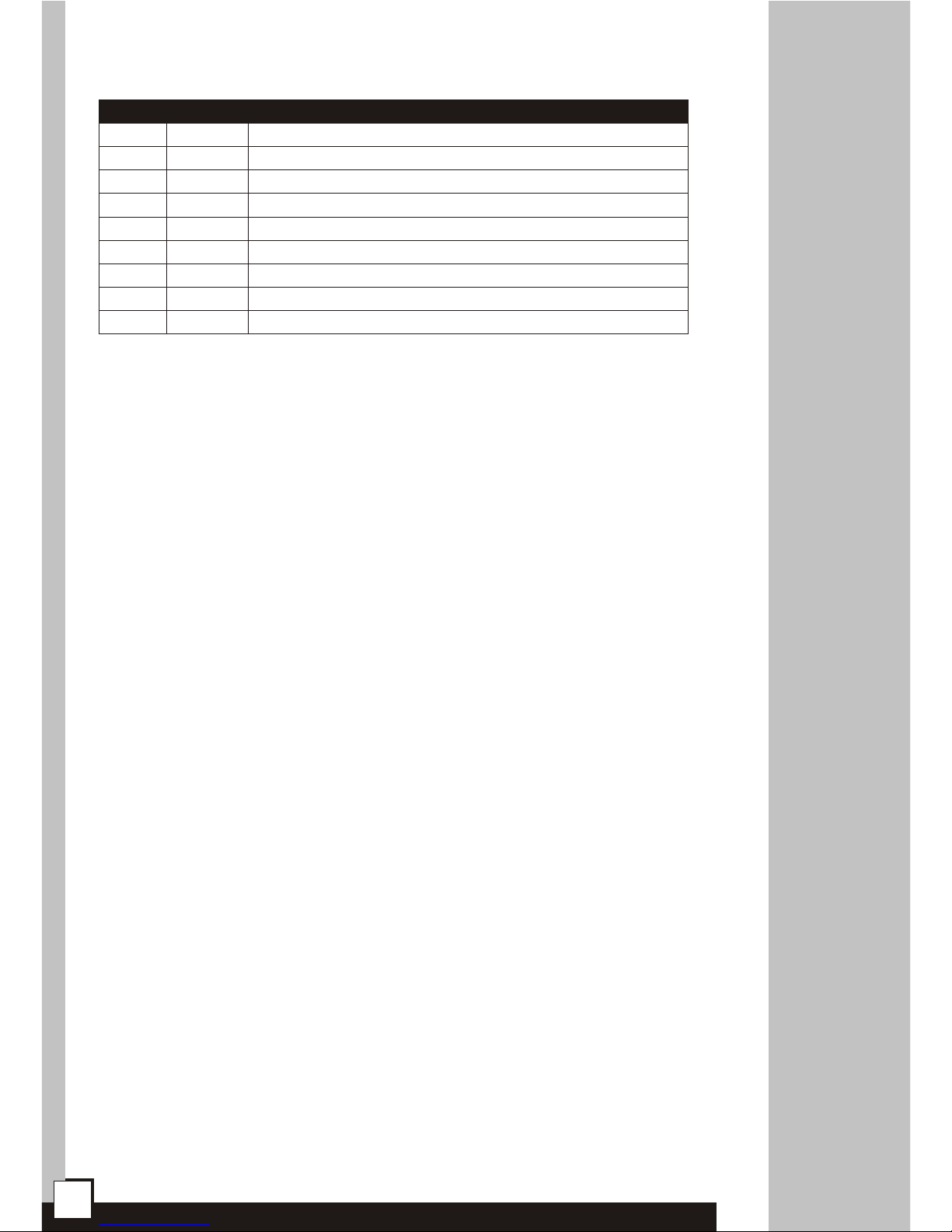
Pin Name
1
DCD
2
3
4
5
6
RXD
TXD
DTR
GND
DSR
Description
carrier detect, transmission readiness signaling
data received from the PC
data sent by the router to the PC
active, when the PC is switched on
signal ground
active, when the router is switched on
7 RTS
used by the PC to inform that is has data to send
8 CTS
used by the router to permit data transmission
9 RI
ring indicator (signal used in telephone modems)

5
3. Configuration and management
3.1. Telnet connection
To connect to the router the network interface in your PC has to be
in the same IP subnet as the router. By default the router’s Ethernet
interface is set to 10.0.0.1 address and 255.0.0.0 netmask, so the PC
may have IP address set to 10.0.0.2 and the same netmask.
If the router was already configured and the routing table is
correctly set up, a telnet connection to its IP address is possible from
anywhere in the network.
After connecting a password prompt will appear:
User Access Verification
Password:
The default password is “Tahoe” (case sensitive). If the
password entered is correct, a command prompt will appear:
Tahoe>
3.2. Serial console
If the telnet connection is not possible (e.g. there’s no telnet client
available or the router’s IP address is unknown), the router may be
connected to the PC’s serial port using a null-modem cable. After starting
a terminal software (e.g. minicom under Linux operating system,
®
Hyperterm under Microsoft Windows™) user gets the same access as
through the telnet connection. After pressing Enter the same command
prompt appears:
Tahoe>
By default the console access isn’t password protected, but such
protection may be enabled later using “console password” command.
3
3.1
3.2

6
3.3. Commands
3.3.1. ?, help
Entering “?” or “help” shows a list of available commands.
3.3.2. arp
The “arp” command is used to configure the ARP table. The “arp”
alone shows the list of connections between IP and hardware (MAC)
addresses:
Tahoe> arp
IP address Hardware address
10.0.0.2 00:50:04:0D:70:31 dynamic
ARP table entries may be deleted using “arp del”:
Tahoe> arp del 10.0.0.2
(the IP address to be deleted should be typed instead of
“10.0.0.2” ).
A static ARP entry may be added using “arp add”:
Tahoe> arp add 10.0.0.3 00:50:13:E9:5C:01
The dynamic hardware address resolution may be disabled using
the “ifconfig” command. If it is disabled, only those stations may connect
to the router, whose IP and MAC addresses are entered into the ARP table
using the “arp add” command. This way an unauthorized network access
may be prohibited.
3.3.3. bridge
The “bridge” command enables or disables the bridge mode, in
which two interconnected LANs create one whole in the hardware layer.
The stations in both LANs behave like if they were connected to one
®
Ethernet switch, e.g. PCs working under Microsoft Windows™
operating system will see each other in the network neighborhood.
Three settings are available:
¡ off - regular TCP/IP routing
¡ on - bridge enabled, but the router is still available under its IP
address and thus may be managed remotely
3.3
 Loading...