

Page 1
TECHNICAL SPECIFICATIONS
Operating Pressure:
Suitable for mains pressure.
Min. 150kPa, Max. 500kPa
Operating Temperature:
Recommended maximum
49°C. Max. 60°C
Inlet Connections:
All 1/2"
All pipework must be
thoroughly flushed prior to
installation of the system.
TAHI SHOWER SYSTEM
INSTALLATION GUIDE
Page 2
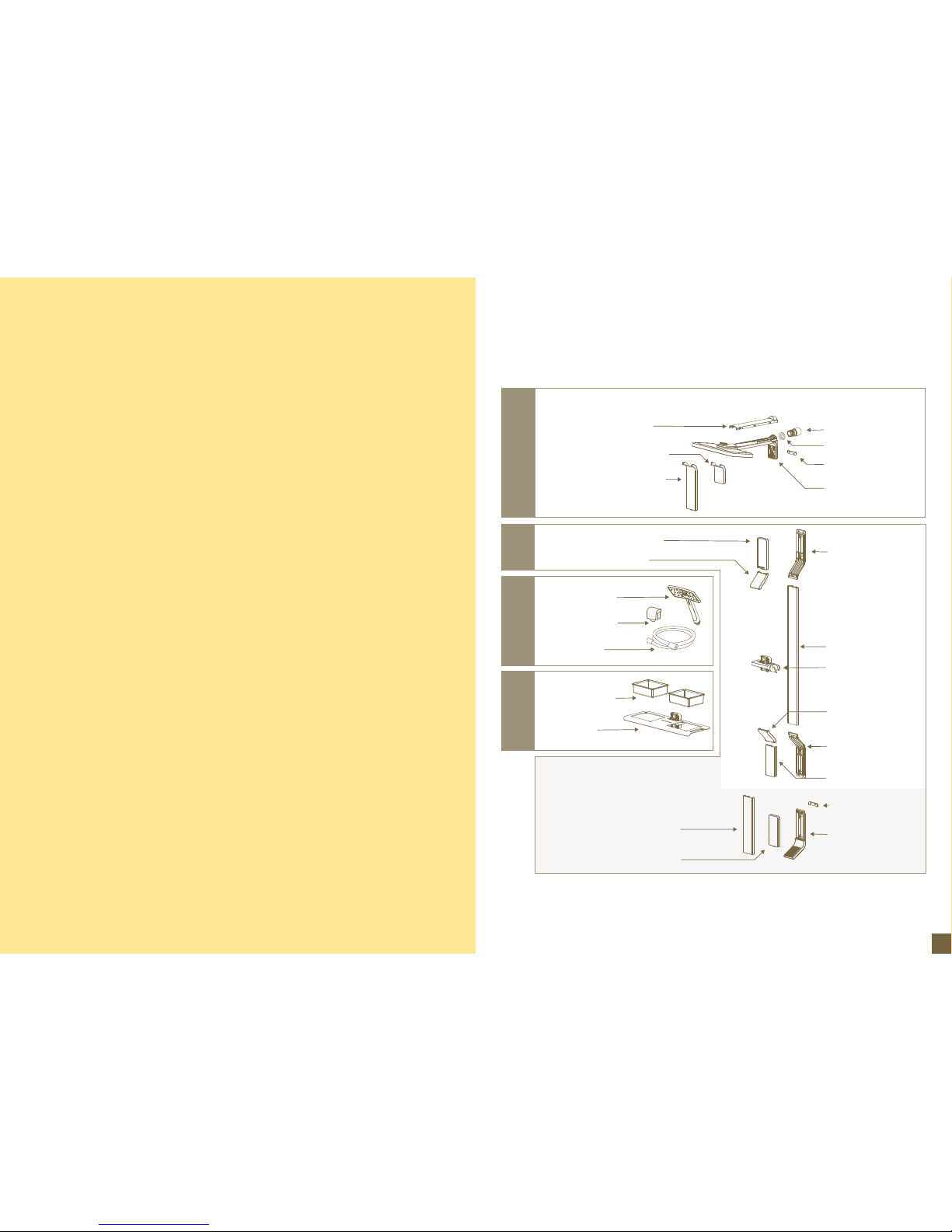
EXPLODED DIAGRAM
Separate footrest cover
Drencher assembly
Separate drencher
spacer
Drencher outlet seal
Drencher arm cover
Separate drencher cover
Rail top bracket cover
Rail top 45° cover
Handpiece
Hose elbow
Hose
Shelf trays
Shelf
Rail bottom 45° cover
Rail bottom
bracket cover
Attached footrest cover
Rail top bracket
Rail
Rail bottom bracket
Separate footrest
spacer
Footrest assembly
Handpiece holder
A
B
C
Only included when you
purchase footrest option.
Drencher outlet
adaptor
Attached drencher cover
(Discard if installing
stand-alone drench shower)
Drench Shower
EXPLODED DIAGRAM
1
Page 3
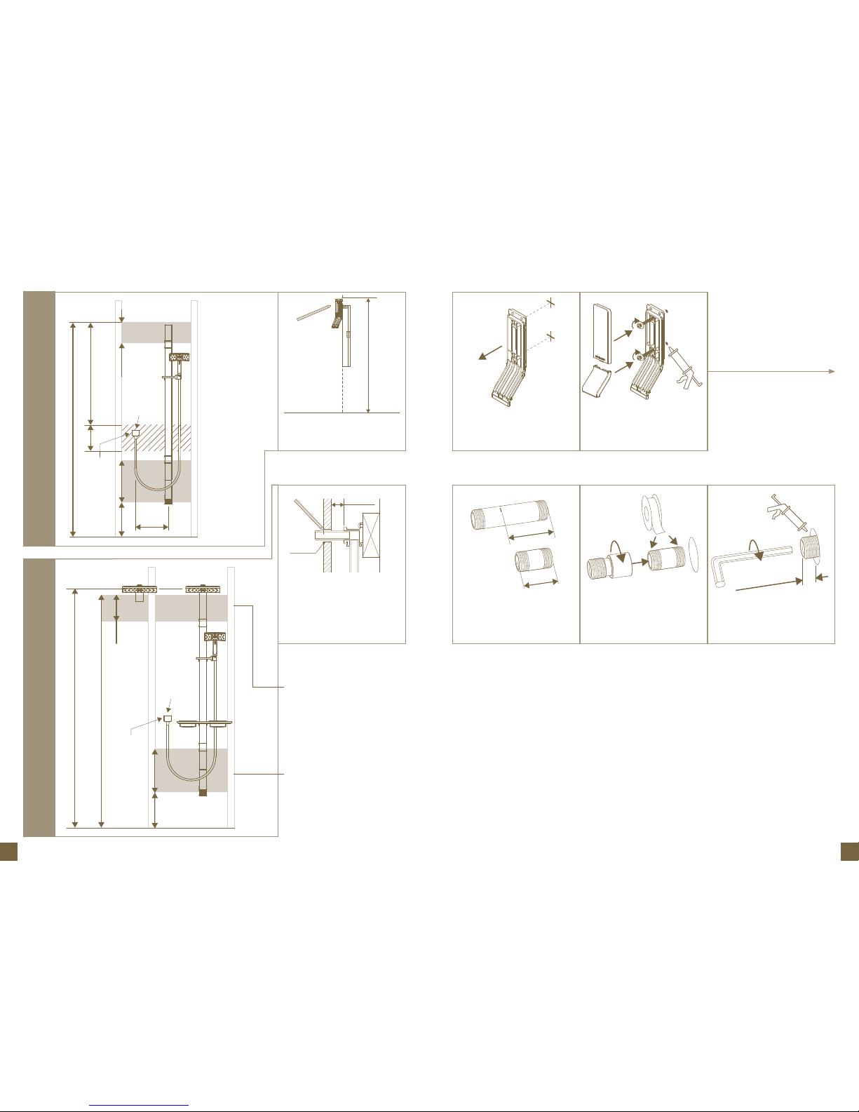
Measure X and subtract 13mm.
This is the length of the brass
nipple required to install the outlet
connector
Set bracket aside, drill clearance
into lining then pre-drill support
Ensure edge is plumb, mark plumb
line to floor and mark screw holes
Wrap both ends of brass nipple
with Teflon tape and screw on
drencher outlet adaptor. Screw
assembly into wingback
Seal holes. Drive in screws (and
wall plugs where appropriate). Clip
on covers
Tighten using using a 10mm hex
key, check dimension and seal the
wall
21 3 4
Go to 12 on page 6
Rail ShowerShower System and Drench Shower
Fastening Zone
– load-bearing
support required
Fastening Zone
– load-bearing
support required
380mm360mm
Hole
Ø25mm
2100mm
Recommended
outlet height
2070mm
240mm
Floor
Elbow height at
installer’s discretion
(Recommended) 2010mm
X
X - 13mm
16mm +/- 3mm
PRE WALL LINING REQUIREMENTS
Install properly anchored female
1/2 wingback at least 25mm from
the front of the unlined wall. Screw
in test nipple. When the wall is
finished mark the test nipple at the
wall surface and remove the nipple
Ø
25mm
25mm (Min.)
Standard Rail
Fastening Zone
-load bearing
support required
Short Rail (13-8302)
Fastening Zone
-load bearing
support required
Fastening Zone
-load bearing
support required
2020mm
930mm
180mm
180mm
Floor
300mm
Min.
Hole
Ø25mm
380mm360mm
Elbow height at
installer’s discretion
2
3
Page 4
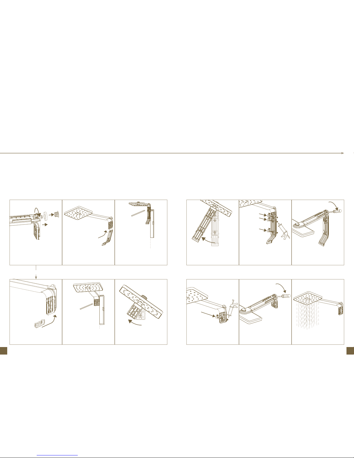
Fit foam seal around nipple. Insert
waterway into outlet and screw nut
on to outlet loosely
Swing aside. Drill clearance into
lining then pre-drill support
Slip spacer under bracket
Seal hole and drive in screw (and
wall plug if appropriate)
Slip top rail bracket under
drencher bracket
Seal holes and drive in screws (and
wall plugs if appropriate)
Ensure edge of bracket is plumb
then mark bottom screw hole
Tighten using a lever until bracket
is pulled flat against wall
Ensure edge is plumb, mark plumb
line to floor and mark screw holes
Tighten using a lever until bracket
is pulled flat against wall
Swing aside. Drill clearance into
lining then pre-drill support
Run water to ensure the unit is
sealed
5 86 97 10
Drencher only
4
5
Page 5
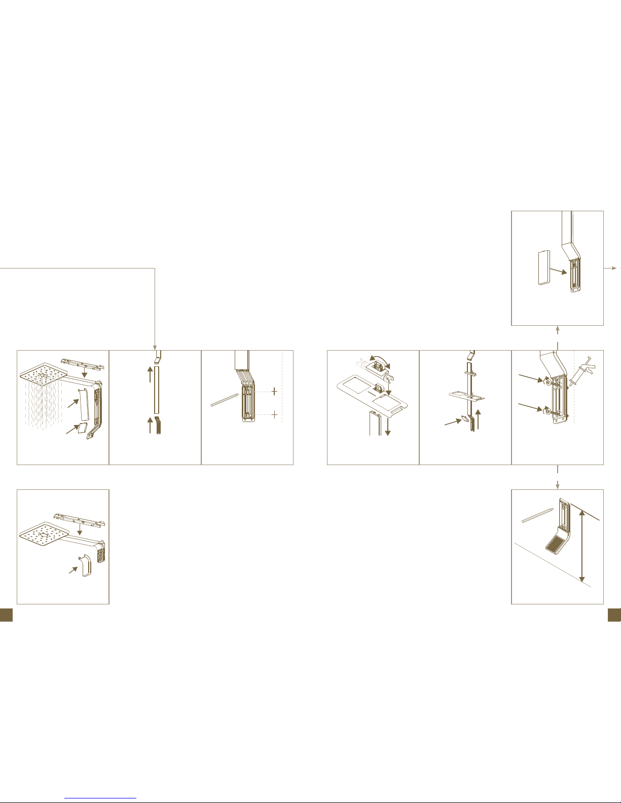
11 1412 1513 16
Run water to ensure the unit is
sealed, then clip on covers
Clip on covers
Push rail and bottom rail bracket
hard on to mounted top bracket
Ensure edge aligns with plumb line.
Mark holes. Set aside, drill clearance
into lining and pre-drill support
Slide shelf (if included) and
handpiece holder on to top of rail
Push rail and bracket back on to
top bracket and clip on angled
cover
Seal holes. Drive in screws (and
wall plugs where appropriate).
Check alignment with plumb line
Mark holes
No footrest
Separate footrest
Go to 19 on
page 8
Clip on cover
1
2
575mm
6
7
Page 6
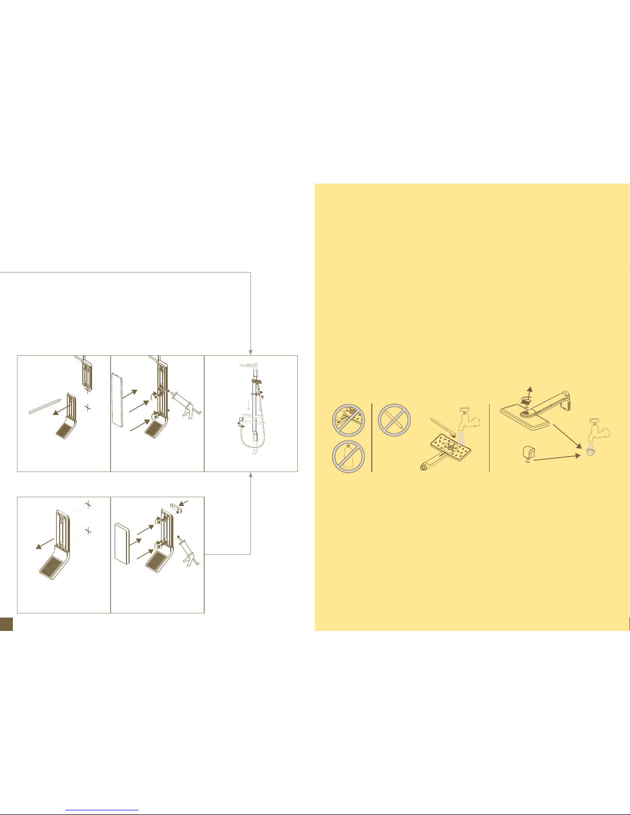
17 18 19
Place footrest and mark holes.
Drill clearance in lining and predrill support
Set footrest aside, drill clearance into
lining then pre-drill support
Seal holes. Drive in screws
(and wall plugs if appropriate).
Clip on cover
Seal holes. Attach footrest cap.
Drive in screws (and wall plugs if
appropriate). Clip on cover
Attach hose and insert trays
Environmental Statement: Removing flow restrictor under filter cap
or in hand shower will increase water consumption.
Clean filter baskets periodically
Do not use any
sharp objects to
clean nozzles
Water contains lime which remains on the surface after
the water has evaporated. These lime deposits can be
prevented from forming by wiping immediately after use.
To clean the chrome-plated surfaces use a soft cloth,
soap and warm water. Never use cleaning agents that
contain a corrosive acid or a scouring additive.
CLEANING
8
Page 7

Methven warrants this product against manufacturing defects and that it is
suitable for use under the operating conditions specified in this instruction sheet.
For your warranty please refer to www.methven.com or call Customer Service
New Zealand
0800 804 222
Australia
1300 638 483
USA
800 975 5409
UK
0800 195 1602
290240 I
ssue A
 Loading...