


GemWave™
Smarto L122 EAS
System
User Guide
Version 3.0
Preliminary
Copyright © TAGSYS, November 2001

FCC Compliance Statement
NOTE: This equipment has been tested and found to comply with the limits for a Class B
digital device, pursuant to part 15 of the FCC Rules. These limits are designed to provide
reasonable protection against harmful interference in a residential installation. This
equipment generates, uses and can radiate radio frequency energy and, if not installed and
used in accordance with the instructions, may cause harmful interference to radio
communications. However, there is no guarantee that interference will not occur in a
particular installation. If this equipment does cause harmful interference to radio or
television reception, which can be determined by turning the equipment off and on, the
user is encouraged to try to correct the interference by one or more of the following
measures:
• Reorient or relocate the receiving antenna
• Increase the separation between the equipment and the receiver
• Connect the equipment to an outlet on a circuit different from that to which the
receiver is connected
• Consult the dealer or an experienced radio/TV technical for help


Specific Warning Notice
All information herein is either public information or is the property of, and owned solely by,
TAGSYS, who shall have and keep the sole right to file patents or applications or any other kind of
intellectual property protection in connection with such information.
Nothing herein shall be construed as implying or granting to you any rights by licence, grant or
otherwise, under any intellectual and/or industrial property rights of or concerning any of TAGSYS'
information.
This document can be used for informational, non-commercial, internal and personal use only provided
that:
@ the copyright notice below, the confidentiality and proprietary legend and this full warning
notice appear in all copies
@ this document shall not be posted on any network computer or broadcast in any media, and no
modification of any part of this document shall be made
Use for any other purpose is expressly prohibited and may result in severe civil and criminal liabilities.
The information contained in this document is provided "AS IS "without any warranty of any kind.
Unless otherwise expressly agreed in writing, TAGSYS makes no warranty as to the value or accuracy
of information contained herein. The document could include technical inaccuracies or typographical
errors. Changes are periodically added to the information herein. Furthermore, TAGSYS reserves the
right to make any change or improvement in the specifications data, information, and the like described
herein, at any time.
TAGSYS hereby disclaims all warranties and conditions with regard to the information
contained herein, including all implied warranties of merchantability, fitness for a particular
purpose, title and non-infringement. In no event shall TAGSYS be liable, whether in contract,
tort or otherwise, for any indirect, special or consequential damages or any damages
whatsoever including, but not limited to, damages resulting from loss of use, data, profits,
revenues, or customers, arising out of or in connection with the use or performance of
information contained in this document.
TAGSYS does not and shall not warrant that this product/system/equipment will be resistant
to all possible attacks, and shall not incur, and disclaims, any liability in this respect. Even if
each product is compliant with current security standards in force on the date of their design,
security mechanisms' resistance necessarily evolves according to the state-of-the-art in
security and notably under the emergence of new attacks. Under no circumstances shall
TAGSYS be held liable for any third party actions, and in particular in case of any successful
attack against systems or equipment incorporating TAGSYS products.
TAGSYS disclaims any liability with respect to security for direct, indirect, incidental or
consequential damages that result from any use of its products. It is further stressed that
independent testing and verification by the person using the product is particularly
encouraged, especially in any application in which defective, incorrect, or insecure functioning
could result in damage to persons or property, denial of service, or loss of privacy.
Preliminary
Copyright © TAGSYS
Smart Labels and Couplers are patents protected by TAGSYS and are produced by TAGSYS.
MS-DOS® and Windows® are registered trademarks of Microsoft Corporation.


Contents
WELCOME ................................................................................................................................................1
Assumptions......................................................................................................... 1
About this manual................................................................................................ 2
Getting help ......................................................................................................... 2
Quality assurance................................................................................................. 2
Warranty .............................................................................................................. 3
1 INTRODUCING THE SMARTO L122 EAS SYSTEM .................................................................................5
1.1 Introduction................................................................................................ 5
1.2 Anti-theft system overview......................................................................... 6
Smart labels ................................................................................................ 6
1.3 Smarto L122 EAS system overview............................................................ 8
1.4 Smarto L122 components........................................................................... 8
1.5 Cabling and plug pack.............................................................................. 10
2 OPERATION ......................................................................................................................................13
2.1 Factors affecting operation....................................................................... 13
2.2 Starting the system................................................................................... 14
2.3 Normal operation...................................................................................... 14
2.4 Shutting down.......................................................................................... 14
2.5 Adjusting the buzzer volume .................................................................... 14
3 TROUBLESHOOTING..........................................................................................................................15
3.1 Troubleshooting table............................................................................... 15
3.2 Sources of interference............................................................................. 16
Preliminary
4 TECHNICAL DATA.............................................................................................................................17
4.1 Technical specifications............................................................................ 17
4.2 Spare parts................................................................................................ 17
GLOSSARY..............................................................................................................................................19
ACRONYMS AND ABBREVIATIONS ...........................................................................................................21
Version 2.0 © TAGSYS 2001 Smarto L122 i

List of illustrations
List of illustrations
Figure 1: System overview .......................................................................................................... 7
Figure 2: Pedestals...................................................................................................................... 9
Figure 3: Electronics unit (front and rear) .................................................................................. 10
Preliminary
ii Smarto L122 Version 2.0 © TAGSYS 2001

Welcome
Welcome to GemWave™ Smart Asset Tracking!
Thank you for the confidence you have shown TAGSYS by choosing the
GemWave™ product range.
GemWave™ products can help you implement high-quality Radio Frequency
Identification (RFID) systems for the most demanding applications. They can also
be adapted easily to existing systems.
Assumptions
This User Guide is designed for all TAGSYS partners and for TAGSYS Expert
Network customers implementing a low-cost and high-performance RFID solution.
This document does not assume any knowledge of Radio Frequency (RF)
Identification technology. If you would like more information on this technology, a
good reference source is:
This User Guide assumes the equipment is installed, set up, tuned, and operating
correctly.
Preliminary
"RFID Handbook, Radio Frequency Identification Fundamentals" by Klaus
Finkenzeller, published by John Wiley & Sons UK 1999.
ISBN 0-471-98851-0.
Version 2.0 © TAGSYS 2001 Smarto L122 1
Welcome
About this manual
This document describes the Smarto L122 Electronic Article
Surveillance (EAS) system. This system scans items passing between two or
more pedestals to determine if they have been correctly processed or checked out.
The manual contains:
@ a brief description of the Smarto L122 and explanation of how it works
@ a description of the operations carried out using the unit
@ a troubleshooting table
@ reference information such as technical specifications
@ a glossary and list of abbreviations and acronyms
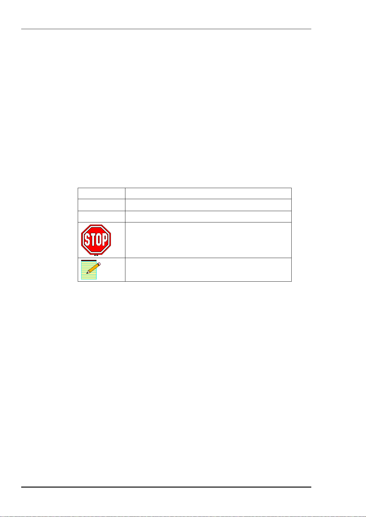
This document uses the following conventions:
Symbol Meaning
@ One of a list of items.
Ø
Getting help
If you require assistance with your Palmo P121 system, please contact your
customer support representative, or TAGSYS.
Preliminary
Quality assurance
TAGSYS implements stringent quality controls in all stages of manufacture. If you
find a defect with this product, please notify your customer service representative.
One of a list of actions.
A warning about safety or hazards, or about actions that
could lead to equipment failures or breakdown.
A note or additional information to which your attention is
drawn.
2 Smarto L122 Version 2.0 © TAGSYS 2001

Warranty
WARNING: This equipment may not be modified, altered, or changed in any way
Welcome
TAGSYS partners and customers are not authorised to modify the Smarto L122.
Any modification invalidates the warranty.
without signed written permission from TAGSYS. Unauthorised
modification may void the equipment authorisation from the FCC and will
void the TAGSYS warranty.
Preliminary
Version 2.0 © TAGSYS 2001 Smarto L122 3

Welcome
Preliminary
4 Smarto L122 Version 2.0 © TAGSYS 2001

Introducing the Smarto
L122 EAS system
1
1.1 Introduction
The GemWave™ Smarto L122 EAS system (see Figure 1) reads information
from microchips embedded in smart labels.
Preliminary
Smart labels are small tags, which may be injected into plastic for protection from
hostile environments. They have numerous applications such as managing the
borrowing and return of books or tracking laundry articles. As well as providing
identification, smart labels can also prevent theft by triggering an alarm if the
labelled item is not checked out or processed correctly.
Theft prevention has traditionally been performed by single bit magnetic and
electromagnetic tags used only for theft prevention, but the smart labels used in the
Smarto L122 EAS system have the EAS capability built into the smart label,
along with identification and other information.
Version 2.0 © TAGSYS 2001 Smarto L122 5

Introducing the Smarto L122 EAS system
1.2 Anti-theft system overview
The anti-theft system is called an Electronic Article Surveillance (EAS) system and
comprises:
@ at least one pair of vertical Aero L122 EAS pedestals forming a ‘gate’
(called an EAS gate) at the building or room entry/exit point
@ a Medio L122 EAS electronics unit for each pedestal, to drive the system
Each item to be checked is labelled with a ‘smart label’ (see below) that includes
identifying information about the item. Part of the information on the label is the
theft status, encoded on a ‘theft bit’, which is either ON or OFF. When the item is
being processed, for example, by being checked out of the library, the theft status is
changed to OFF.
The labelled articles (such as library books) are passed or carried through the gate.
Pedestrian traffic is only allowed between the pedestals. As the item passes between
the pedestals the status of the theft bit is detected. If it is ON, a panel of lights at the
top of the pedestal flashes, and a buzzer may sound.
Smart labels
A smart label consists of a silicon microchip (C220 type) connected to an antenna
etched on to the label substrate. When the label passes through the electromagnetic
field produced by the antennas inside the EAS pedestal, the label begins to send
information about the theft status. This information can be detected even when the
label is invisible to the pedestal, or if it is covered in grime or dirt or in a
challenging environment.
The smart labels used in this system are of the passive type, which means they do
not have an internal power source and derive their power from the EAS pedestal
antennas. Their operational lifetime is virtually unlimited.
The GemWave C220 microchip is available on a number of styles and sizes of smart
labels. The performance of each of these types varies, and some may not provide
performance suitable for EAS systems.
Theft bit
The smart label may have up to 128 bits of information programmed into it. One of
these ‘bits’ of information is the theft bit. This bit must be in one of two states: ON
(enabled or set) or OFF (disabled or cleared).
Preliminary
When the theft bit in a smart label is ON, the label transmits a short burst of reply
(the ‘EAS burst’) when in the electromagnetic field of the EAS gate antennas. This
short burst is detected by the antennas and the alarm is raised. If the theft bit is off,
the EAS burst is disabled and no alarm results.
6 Smarto L122 Version 2.0 © TAGSYS 2001

Figure 1: System overview
Introducing the Smarto L122 EAS system
Preliminary
Version 2.0 © TAGSYS 2001 Smarto L122 7

Introducing the Smarto L122 EAS system
1.3 Smarto L122 EAS system overview
The Smarto L122 system (see Figure 1) consists of:
@ pedestals—normally two or more between which items pass for theft
detection, and which raise an alarm if an item has not been correctly
processed
@ smart label—attached to the item(s) to be checked for theft status, and
includes a transponder programmed with information to identify the object
to which it is attached, and a tiny antenna etched onto the label substrate
@ Medio L122 electronics unit—applies radio waves to a pedestal to
interrogate smart labels near the pedestal
1.4 Smarto L122 components
The Smarto L122 components are located in the Aero L122 pedestal and the
Medio L122 electronics unit.
Pedestal components
Each pedestal acts independently of any others, though it must be synchronised with
all other pedestals in the building, and with the phases of the mains power supply, to
function correctly. The maximum number of pedestals in close proximity to each
other is eight.
Note: If the pedestals are not correctly tuned and synchronised, they may interfere with
each other and produce anomalous results.
The set of pedestals at an entrance or exit is termed an EAS gate, and may comprise
up to four pedestals. A pair of pedestals is shown below.
Preliminary
8 Smarto L122 Version 2.0 © TAGSYS 2001

Figure 2: Pedestals
Introducing the Smarto L122 EAS system
The following components form the pedestal:
@ chassis — a supporting frame fixed to the floor
Preliminary
@ flasher unit — produces a visual alarm at the top of the pedestal (a buzzer is
also provided)
@ antennas — three antennas, which detect theft bit information from the
smart labels
@ adaptor board — connection point for cables to the electronics unit, the
antennas, and the flasher unit
PIR (passive infrared) sensors are also mounted on this board for detecting
the presence of people near the pedestals.
@ mountings — fix the chassis to the floor, and strong enough to ensure the
pedestal will not collapse even if an average sized person falls against it
@ cover and seal — plastic cover in two halves with a flasher and a rubber
seal between the halves
Version 2.0 © TAGSYS 2001 Smarto L122 9

Introducing the Smarto L122 EAS system
Electronics unit components
Each pedestal is cabled to a Medio L122 EAS electronics unit that reads
information from the smart labels passing between the pedestals.
The electronics unit has two small indicator lights. The green light should be on
when the electronics unit has power. The red light should be on whenever the
flasher unit on the pedestal is flashing to indicate a smart label with theft bit ON has
been detected.
WARNING: The electronics unit contains no operator serviceable parts and must only
be serviced by qualified personnel.
Figure 3: Electronics unit (front and rear)
Connections to:
plug pack optional outputs pedestal adaptor board
Note: The electronics unit is not fused and does not contain any fans, batteries or
insulated interconnecting wiring.
Preliminary
1.5 Cabling and plug pack
The pedestals are supplied with all internal wiring and cabling connected. The cable
from the electronics unit to the adaptor board provides received (Rx) and transmitted
(Tx) signals to and from the pedestal, and power for the flasher unit.
The mains power supply to the electronics unit is a separate wall plug style linear
mains pack that converts the local mains power to 12 V AC, 1 Amp power at 50 Hz
or 60 Hz. A separate plug pack should be provided for each pedestal.
The plug pack must be purchased locally to suit the voltage and frequency ratings of
the national supply. It must meet the national regulations for the country in which it
is installed. Full specifications are included in Section 4.1
10 Smarto L122 Version 2.0 © TAGSYS 2001

Introducing the Smarto L122 EAS system
SMARTO L122 FCC EQUIPMENT STATEMENT
WARNING TO USERS IN THE UNITED STATES
FEDERAL COMMUNCIATIONS COMMISSION (FCC) RADIO
INTERFERENCE STATEMENT 47 CFR Section 15.105(b)
This equipment has been tested and found to comply with the limits for a Class B digital device,
pursuant to Part 15 of the FCC Rules. These limits are designed to provide reasonable protection
against harmful interference in a residential installation. This equipment generates, uses and can
radiate radio frequency energy and if not installed and used in accordance with the instructions
may cause harmful interference to radio communications. However, there is no guarantee that
interference will not occur in a particular installation. If this equipment does cause harmful
interference to radio or television reception, which can be determined by turning the equipment
off and on, the user is encouraged to try to correct the interference by one or more of the
following measures:
Ø Reorient or relocate the receiving antenna.
Ø Increase the separation between the equipment and receiver.
Ø Connect the equipment into an outlet on a circuit different to
that to which the receiver is connected.
Ø Consult the dealer or an experienced radio/TV technician for
help.
NO UNAUTHORISED MODIFICATIONS
47 CFR Section 15.21
CAUTION: This equipment may not be modified, altered, or changed in any way without signed
written permission from TAGSYS Australia Pty Ltd. Unauthorised modification may void the
equipment authorisation from the FCC and will void the TAGSYS warranty.
Preliminary
CAUTION: This equipment must be professionally installed. The installer shall be responsible
for ensuring that the proper antenna is employed so that the limits in this part are not exceeded.
Non-professional installation or installation of the equipment with an improper antenna may void
the equipment authorisation from the FCC and will void the TAGSYS warranty.
ANTENNA REQUIREMENT
47 CFR Section 15.203
Version 2.0 © TAGSYS 2001 Smarto L122 11

Introducing the Smarto L122 EAS system
Preliminary
12 Smarto L122 Version 2.0 © TAGSYS 2001

Operation
Note: This device complies with part 15 of the FCC rules. Operation is subject to the
following two conditions:(1) This device may not cause harmful interference, and
(2) This device must accept any interference received, including interference that
may cause undesired operation.
2
2.1 Factors affecting operation
Other electronic equipment within two to five metres of EAS pedestals (such as
Preliminary
borrowing stations) can interfere with the performance of the system in the
following ways:
@ smart label couplers emit an electromagnetic field that can interfere with the
sensitivity of nearby pedestal antennas
@ the smart label's response to the nearby coupler can be picked up on the
EAS pedestals if it contains EAS information
A minimum of five metres1 is recommended between an EAS pedestal and any
other reader system or antenna such as that on a return chute. Where borrowing
stations and other Library RFID modules are used, and where smart labels are being
programmed, we recommend a minimum of ten metres. In this case a fully shielded
antenna is also necessary. Refer to Chapter 3 for further information on interference.
1
Subject to site variables. Distance may be less under some conditions. Metal frames on furniture and fixture
items may interfere with the EAS system if they are too close. This is because energy from the antenna can couple
into the metallic frame and be transmitted to smart labels and antennas several metres away. Consult your TAGSYS
partner for advice on installing and positioning the pedestals.
Version 2.0 © TAGSYS 2001 Smarto L122 13

Operation
2.2 Starting the system
If possible, each pedestal plug pack should be connected to a single board with a
single mains switch to ensure all pedestals are powered simultaneously.
There is no on/off switch. As long as the system is correctly cabled and all
connections are good, the system operates when power is applied.
2.3 Normal operation
No operating procedures are required. The system continues to operate as long as it
is plugged in.
2.4 Shutting down
Do not shut the system down unless absolutely necessary.
WARNING: We recommend all pedestals in the building remain on at all times.
2.5 Adjusting the buzzer volume
The buzzer volume may be adjusted with the potentiometer on the top of the
pedestal, above the flasher unit.
To gain access to the trim pot, separate the covers from the pedestal chassis and
remove the pedestal seal from the top of the pedestal cover sufficiently to access the
trim pot. To adjust the volume, turn the trimpot — clockwise to increase buzzer
volume, or anti-clockwise to decrease the volume.
Preliminary
14 Smarto L122 Version 2.0 © TAGSYS 2001

Troubleshooting
3.1 Troubleshooting table
Fault Possible causes Remedies
No power. Cabling fault. Check cabling and connections.
Replace any suspected faulty cables.
3
Alarms missed (smart
labels with theft bit ON
not triggering alarms).
No detection of smart
labels.
False alarms (smart
labels with theft bit OFF
trigger alarms).
Plug pack fault. Replace plug pack.
Tuning fault.
One or more of the inputs
or outputs not functioning
Preliminary
correctly.
No RF output pulse power
from the multiplexer to the
antenna.
Nearby devices are
interfering with the
pedestals. (Refer also to
Section 3.2.)
Tuning fault. Call your TAGSYS customer service
Call your TAGSYS customer service
representative.
Call your TAGSYS customer service
representative.
Call your TAGSYS customer service
representative.
Switch off all or some of the suspicious
nearby devices and check if the EAS detection
performance changes. (If not, call your
TAGSYS customer service representative.)
representative.
Version 2.0 © TAGSYS 2001 Smarto L122 15

Troubleshooting
3.2 Sources of interference
The following devices may cause interference with EAS systems when in close
proximity (within approximately ten metres) of pedestals:
@ smart label couplers and programming devices
@ computers
@ radios tuned to the SW region
@ high power music systems with D-class amplifiers
@ some industrial vacuum cleaners
@ high frequency fluorescent lights (if very close to pedestals)
@ neon lights such as advertising signs
@ equipment using switch mode power supplies
@ data or power cables within 400 mm
@ illuminated exit signs generating 80–100 kHz noise
@ digital phone lines (wideband noise)
Note: Contact customer support for advice on installation or any interference problems
experienced.
Preliminary
16 Smarto L122 Version 2.0 © TAGSYS 2001

Technical data
4
4.1 Technical specifications
Feature Details
Microchip compatibility GemWave C220
Operating conditions 0°C to 55°C
Storage temperature -20°C to 70°C
Weight Electronics: 1.1 kg
Conformity
Power supply 12V AC 1 Amp 50/60 Hz
4.2 Spare parts
Preliminary
Pedestal: 17 kg
FCC Part 15, CE; C-Tick, UL, IEC 60950
(Applications pending at time of printing.)
Please contact TAGSYS for any spare parts you require.
Version 2.0 © TAGSYS 2001 Smarto L122 17

Technical data
Preliminary
18 Smarto L122 Version 2.0 © TAGSYS 2001

Glossary
The following terms apply to RFID technology. Not all of these terms appear in this
document.
Term Description
Antenna
Baud A transmission speed rate representing the number of signalling events
Bit A single character in a binary processing system.
BNC connector Cylindrical metal connector with a copper core that is located at the tip
Byte
Coupler An electronic device enabling communication between smart labels
GemWave™ TAGSYS' range of products operating at the 13.56 MHz frequency.
Hexadecimal A system based on the number 16, in which numbers are made up of
IEC connector
Preliminary
An aerial that receives and/or transmits radio frequency signals.
Aerials are manufactured in a variety of forms, shapes and sizes.
per unit time.
of a coaxial cable, and is used to connect cables together. It attaches by
pushing and twisting the outer cylinder on to two locking pins.
A group of eight bits used to represent characters in a binary
processing system.
and host computers.
the digits 0 to 9 and letters A to F. Often used in computer systems
instead of long strings of binary digits.
Three-pin connector used on sockets that carry mains electricity to the
computer. All PCs use a male IEC connector and mains lead with a
female IEC connector.
Interrogation
pulse
Microchip An integrated circuit in which all components are on a single piece of
Reader This term is interchangeable with coupler.
RFID
Version 2.0 © TAGSYS 2001 Smarto L122 19
A signal transmitted by the coupler to activate the smart label’s
transponder.
semi-conductor material.
An automatic identification and data capture system comprising one or
more couplers and one or more smart labels, in which data transfer is
achieved by means of suitable modulated inductive or radiating
electromagnetic carriers.

Glossary
Term Description
Smart label Small, flexible tag belonging to TAGSYS' 13.56 MHz GemWave™
product line. It consists of a chip connected to an antenna etched on a
substrate (such as plastic film).
Tag This term is often used interchangeably with smart label.
Transceiver A combined transmitter and receiver.
Transponder A combined receiver/transmitter that automatically transmits a signal
when a ‘trigger’ is received by it. The trigger is often a pulse, called an
interrogation pulse.
Preliminary
20 Smarto L122 Version 2.0 © TAGSYS 2001

Acronyms and
abbreviations
The following abbreviations and acronyms apply to RFID technology. Not all of
these terms appear in this document.
Abbreviation Meaning
AC Alternating Current
CEC Canadian Electrical Code
CRC Cyclic Redundancy Check
EAS Electronic Article Surveillance
ETX End of Text
GRT General Response Time
NEC National Electrical Code
NYI Not Yet Implemented
Preliminary
PC Personal Computer
PIR Passive Infrared
RAM Random Access Memory
RF Radio Frequency
RFID Radio Frequency Identification system
STX Start of Text
TEP Transmit Enable Pulse
Version 2.0 © TAGSYS 2001 Smarto L122 21

Acronyms and abbreviations
Preliminary
22 Smarto L122 Version 2.0 © TAGSYS 2001
 Loading...