


GemWave™
C220 Chip & Medio L120/L121
Technical Description
Version 1.0
GEMPLUS
March 22 2000

C220 Chips & L120/L121 Couplers - Technical Description
Version 1.0
CONTENTS
GEMWAVE L120/L121 SMART TRACKING ........................................................................ 2
1 THEORY OF OPERATION................................................................................................... 2
2 COMPARISON WITH LOW FREQUENCY SYSTEMS .................................................................... 4
3 GEMWAVE SMART LABELS............................................................................................... 4
4 GEMWAVE ANTENNAS..................................................................................................... 5
4.1 Antenna field regions ............................................................................................ 6
4.2 External loop antenna (Standard) ........................................................................... 7
4.3 Dual polarized loop antenna.................................................................................. 7
4.4 Truck mounted loop antenna................................................................................. 8
4.5 AC206 Metal mounted antenna.............................................................................. 8
5 GEMWAVE MEDIO L120/L121 COUPLERS ........................................................................ 9
51 Coupler functions.................................................................................................. 9
5.2 System construction ...........................................................................................10
53 RF Section ..........................................................................................................10
54 CPU Section .......................................................................................................13
5.5 Power Supply......................................................................................................16
GEMWAVE C220 & L120/L121 SMART TRACKING
The GemWave Smart Tracking system offers extremely low cost smart labels for
use in shorter read range high volume areas such as library book identification,
transport and logistical labels, waste management etc. Read range is limited to
around 500-mm but the system offers very high read rates (up to 70 times per
second) making it ideal for use on high speed production lines.
Standard Features for these systems include:
• Low Cost Smart Labels
• High Read Speed
• High immunity to industrial noise
• Full I/O capabilities
• Networking capabilities
1 Theory of operation
The operation of the system can be explained by considering the three major
components of the system. These are the coupler, the antenna and the smart
label.
GEMPLUS COMPANY CONFIDENTIAL Page 2

C220 Chips & L120/L121 Couplers - Technical Description
P
P
P
P
k
Q
Q
Version 1.0
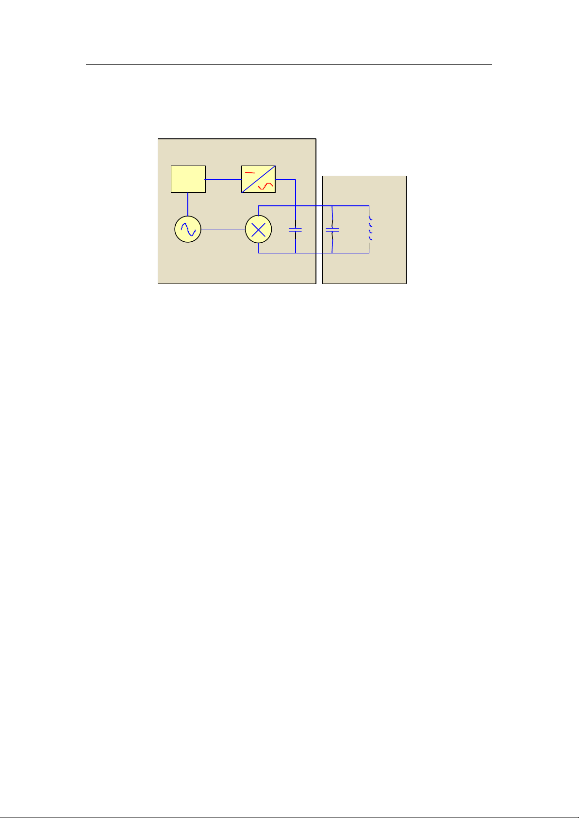
When a smart label is to be read, the coupler transmits an electromagnetic
signal to the labels via the antenna(s). Some of the transmitted energy is incident
on the label, some of this RF (AC) energy is then rectified into a DC level and
used to power the microchip while the remainder is used to carry the smart
label’s unique code back to the coupler.
The process of superimposing the smart labels unique code onto the carrier
frequency is referred to as modulation.
In total, 128 bits1 are transmitted including error detection information, taking a
typical time of 2.4 or 1.2ms (for long and short modes respectively). This data is
picked up by the antenna and decoded. The decoding process occurs in real
time in order to maximize the multiple label reading capabilities of the
L120/L121 couplers.
The power transfer mechanism between the smart label and the coupler is quite
unique and is worthy of a brief discussion. It can easily be shown that the power
transfer ratio of a near field interrogation system is given by
r
2
k QQ
t
t r=
Where
r is the power received by the smart label.
t is the power transmitted by the antenna.
is the coefficient of coupling.
r is the quality factor of the smart label antenna.
t is the quality factor of the transmit antenna.
Thus in order to maximize the received power within the smart label the quality
factors of both the interrogator and the smart label antennas should be made as
high as possible. Practical limitations to this include allowing enough bandwidth
to pass the reply sidebands and the susceptibility of the antenna to detuning due
to environmental influences.
Furthermore, in this type of system, a signal power fall off of approximately
60.log(distance) applies. This implies that the field strength is high in the
immediate vicinity of the antenna but a very low level exists in the far field, hence
well confined interrogation regions can be easily created. Under these
conditions, it can be shown that sixty four times more input power to the antenna
is required to double the read range.
When specifying GemWave C220 systems, it is important to keep in mind the
vortex nature of magnetic fields. This implies always ensuring an adequate path
for the field to circulate. It is also equally important to have a clear understanding
of the field patterns produced by these antennas to ensure that the smart labels
are in the correct orientation to read. For the best performance, the smart labels
GEMPLUS COMPANY CONFIDENTIAL Page 3

C220 Chips & L120/L121 Couplers - Technical Description
Version 1.0
must always have their coil perpendicular to the direction of the field. If the smart
label is placed parallel to the field it will receive no power and will not work.
2 Comparison with low frequency systems
At these relatively low frequencies (13.56 MHz) there are several operational
characteristics that make these systems attractive for many applications.
Perhaps, the most significant of these is cost. Since at these frequencies all the
necessary components have been completely integrated into the proprietary
microchip, the smart label production costs are kept to a minimum. The next
most important characteristic of this frequency is that it allows much faster data
rates than its lower frequency counterparts.
The sub carrier modulation on the GemWave C220 chip allows greater than 70
reads per second to be achieved compared to 10 for our lower frequency
competitors.
Further advantages include the relative immunity to attenuation by non-metallic
objects placed in the interrogation path and the inherent hard cut off that ensures
the interrogation field is clearly defined.
Whilst being low enough in frequency not to be impaired by environmental
hazards that degrade the performance of UHF systems (such as water), HF
frequencies are considered to be high enough to be less susceptible to man
made noise due to motors, welding equipment, computers etc. that plague low
frequency systems often to the point of rendering them useless.
3 GemWave C220 Smart Labels
One of the major advantages of working in the 13.5MHz ISM band is the level of
integration possible in the smart labels. The tag antenna is less complex than for
the lower frequency systems because the value of inductance required to
resonate the tag decreases with increasing frequency. The tuning capacitor can
be integrated, which is impossible (or least uneconomical) at lower frequencies.
Low power semiconductor processes have not yet reached a level where UHF
tags can be completely integrated2, mainly due to efficiency of the rectifiers at
these frequencies.
There is a wide range of standard GemWave tags available for these systems
that are suitable for use in a variety of applications. These are presented in the
various GEMPLUS GemWave Marketing information sources.
Of the several GemWave chips we are concentrating on the proprietary
GemWave C220 chip, which not only features completely integrated rectifiers,
modulators and tuning capacitors but also contains a 128-bit EEPROM cell that
GEMPLUS COMPANY CONFIDENTIAL Page 4
C220 Chips & L120/L121 Couplers - Technical Description
MODULATOR
FSK OSCILLATOR
DC GENERATION
EEPROM
Lantenna
Cantenna
Cchip
C220
MEMORY
ANTENNA
Version 1.0
allows contactless programming. A simplified block diagram of a complete
C220 smart label is shown in Figure 1.
Figure 1: Simplified block diagram of a GemWave C220 Smart label
The GemWave C220 chip uses a Differential Frequency Shift Keyed (DFSK)
sub carrier where a logic “0” forces a change in frequency of the sub carrier
oscillator. This gives the chip excellent performance in noisy environments typical
for industrial installations.
The need for error correction and detection means that only 733 out of 128 bits
are available for use by the customer during programming.
It is important to realize that the maximum read range that can be achieved with
these systems is a function of the smart label size and antenna size, their relative
positions to each other and the power available at the antenna.
It should be noted that C220 based smart labels are not suitable for extreme high
temperature applications due to the temperature limitations of the microchip’s on
board EEPROM memory.
4 GemWave antennas
GemWave antennas use the current flowing in the antenna inductor to produce
the AC magnetic field that is used to power the smart labels. It is important with
these systems to always ensure an adequate path for this field to circulate. This
implies that if either the smart label or the antenna is to be mounted on or near
metal to ensure that the coil is always perpendicular to the metal.
In some circumstances, it is necessary to tune the antennas at the time of
installation since the environment cannot always be predicted at the time of
GEMPLUS COMPANY CONFIDENTIAL Page 5
C220 Chips & L120/L121 Couplers - Technical Description
Version 1.0
manufacture. However most of the time the antenna will perform adequately as
long as care is taken with respect antenna installation.
A wide variety of antennas suitable for GemWave systems have been developed
because of the wide range of applications for this technology requiring different
antenna configurations. The Professional Services Team at GEMPLUS is
always prepared to discuss antenna(s) for your applications.
It should be noted that GEMPLUS is currently in the process of reviewing an
antenna tuning aid that will soon be made available to our customers for these
systems. This will allow antennas to be tuned by customers with inexpensive test
equipment.
4.1 Antenna field regions
The field created by GemWave antennas can be considered to be relatively
omnidirectional. However, the field is more concentrated is certain regions and
smart label orientation with respect to the antenna is important to ensure
optimum performance.
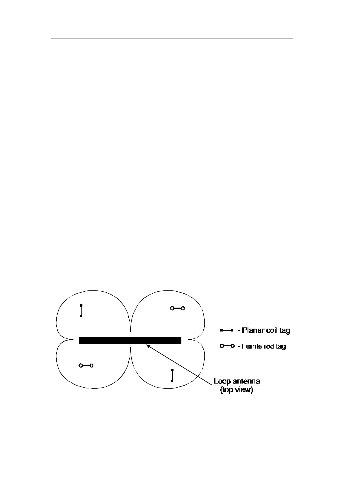
If it is accepted that the field is circulating around the conductors of the antenna,
then Figure 2 and Figure 3 show the regions of space where the field will be able
to excite a smart label in different orientations. (i.e. the points at which the
magnetic field will be at ninety degrees to the smart label’s coil)
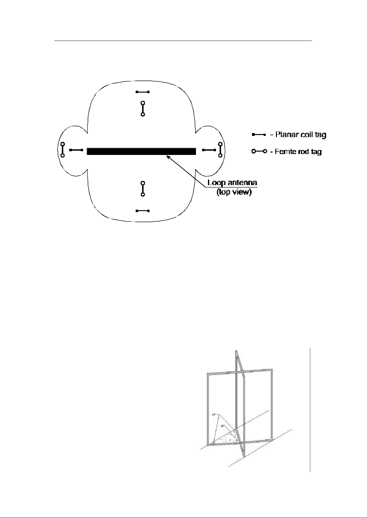
The field regions shown in Figure 2 will give a shorter read range than the
regions in figure 3, however, this orientation can be useful in certain applications.
Figure 2: Field regions for a planar loop antenna for non-optimum smart label
presentation
GEMPLUS COMPANY CONFIDENTIAL Page 6
C220 Chips & L120/L121 Couplers - Technical Description
Version 1.0
An example of a planar coil smart label is a Folio20 and an example of a ferrite
rod smart label is a TC251.
Figure 3 : Field region s for a planar loop antenna for optimum smart label
presentation
4.2 AC201, AC202 and AC212 loop antennas
This range of standard antennas available with GemWave L120 and L121
systems provide a good range of size and performance options. Please refer to
the Data sheet for each of these devices.
4.3 Dual polarized loop antenna
This antenna was originally developed to
identify cattle in a raceway, however its
simple construction and ruggedness
makes it an ideal for any applications
that require fast accurate identification
where smart label orientation cannot be
guaranteed. The larger size originally
made would require a site license for
legal operation, smaller versions for
conveyor application etc. can be made.
GEMPLUS COMPANY CONFIDENTIAL Page 7
C220 Chips & L120/L121 Couplers - Technical Description
ANTENNA
READER
Version 1.0
Figure 4: Dual polarized loop antenna
This antenna provides omnidirectional reading in the vertical plane and will read
a smart label placed anywhere within the loops. It can be constructed in almost
any size ranging up to 820mm x 2000mm for doorway access.
It should be noted that this antenna has also been adapted to allow complete
omnidirectional reading in all planes and is available in a 1m cubic arrangement
(AC205 3D Portal Antenna).
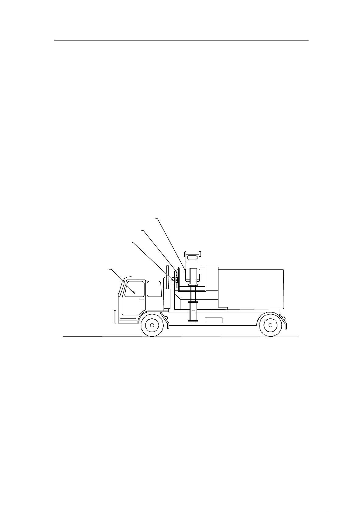
4.4 Truck mounted loop antenna
This antenna measuring 600mm by 350mm is used in the waste management
industry and boasts a read range of up to 500mm. It is similar in construction to
the larger loops and can be adopted for other applications with similar
requirements.
ISD MEDIUM FREQUENCYTAG
ON BOARD COMPUTER /
DATA LOGGER
Figure 5: Waste management application using truck mounted loop antenna
4.5 AC206 Metal Mount antenna
These antennas available with GemWave L120/L121 systems provide an
antenna that can be used in metallic environments where loop type antennas
cannot be used. It is tuned for use directly mounted to metal. We have used it on
Forklifts, in conveyor systems and in various other applications.
GEMPLUS COMPANY CONFIDENTIAL Page 8

C220 Chips & L120/L121 Couplers - Technical Description
Version 1.0
GemWave L120 & L121 Couplers
The GemWave L120/L121 couplers were the first HF near field RFID systems
available in the world. They have proven to be extremely robust in harsh
environments where lower frequency systems have failed due to high levels of
industrial noise. The coupler can both read labels and also program them.
5.1 L120/L121 Coupler functions
The primary functions of the Medio L120/L121 coupler are to provide the
following:
• The generation of a RF signal of the required frequency, power level
and pulse width (or continuous signal as required) for use as the
interrogation rf power a portion of which is backscattered by the smart
label.
• Reception of the reply signal from an identification smart label placed
in the RF field.
• Decoding of the unique identity code from a smart label reply and
output the result to one or more peripherals devices.
• Producing a programming signal to write new data into the C220
smart label.
Some of the secondary functions include:
• Control and monitoring of various digital inputs and output bits for
interfacing to external equipment or additional interrogators.
• Operation of a set of relay changeover contacts for the control of
external functions.
• Data transfer to and from external peripherals using two available
serial ports. These ports can be hardware configured for a range of baud
rates, parity settings and stop bits. One port provides RS232 capabilities
only whilst the second can be configured for RS232, RS422 or RS485.
• Storage of smart label replies in battery backed SRAM for
transmission to external peripherals at a later time.
• Time and date stamping of smart label replies using a battery backed
real time clock.
GEMPLUS COMPANY CONFIDENTIAL Page 9

C220 Chips & L120/L121 Couplers - Technical Description
Version 1.0
• RF multiplexing of the transmitter and receiver signal in multi-antenna
configurations.
5.2 System construction
The Interrogator Unit is housed in a polycarbonate plastic moulded case (IP55
for L120 and IP65 for L121 (these may be changed to metallic style Eddystone
enclosures in the near future).
Standard electrical connections are made via two separate connectors. The first,
a three-pin male, carries the power for the unit. The second, an eight-pin female,
provides communications and I/O signals.
The standard electronics consist of a transceiver module and power supply. The
transceiver module is composed of RF and CPU boards and will be explained in
the following sections. The transceiver module and power supply is mounted on
a base plate, which is placed inside the enclosure. This base plate can be easily
removed for servicing.
The power supply provides +12 V that is required for the various functions within
the system (the RF board also provides +5 V for the CPU board). The standard
power supply can be configured for either 240 or 110 volts AC mains input and
is located on the base plate adjacent to the transceiver. Other power supply
options may be available on request.
5.3 RF Section
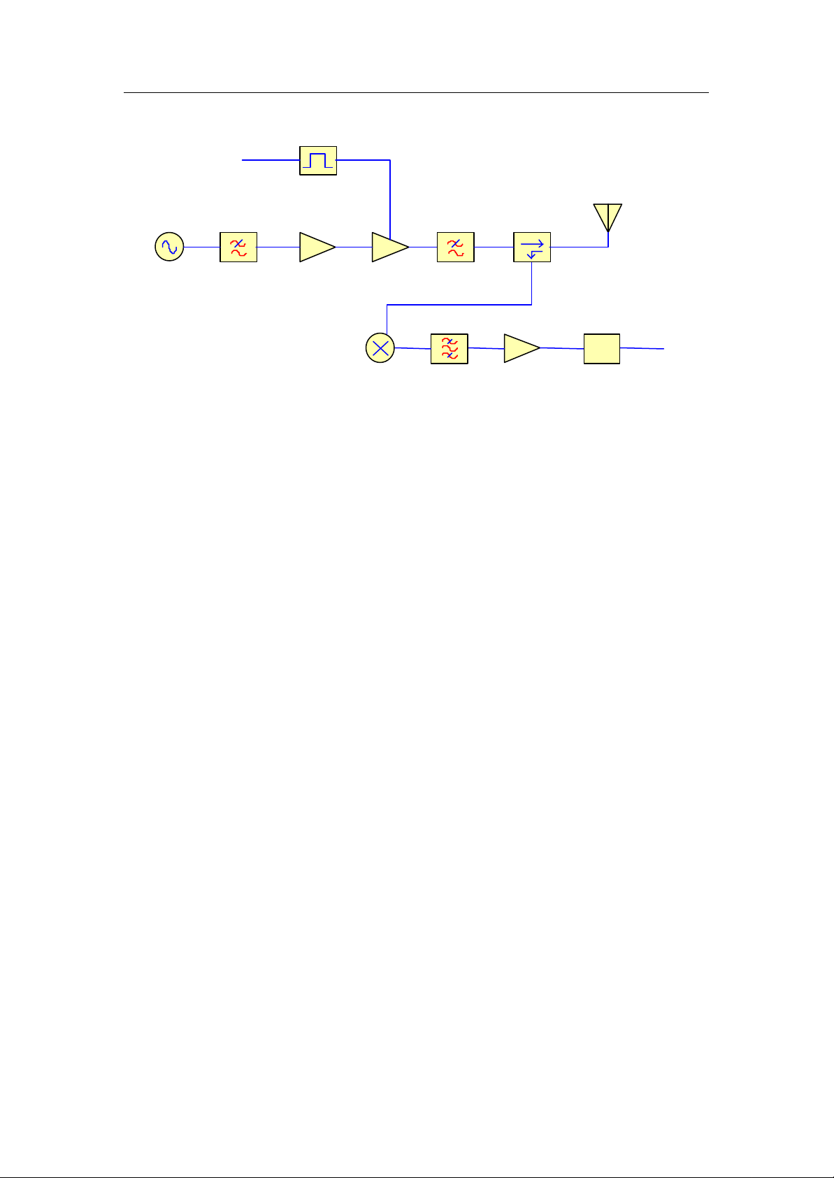
A simple block diagram of the GemWave L120 RF section is shown in Figure 6.
It should be noted that there is a quadrature receiver section rather than the
single channel receiver shown.
GEMPLUS COMPANY CONFIDENTIAL Page 10
C220 Chips & L120/L121 Couplers - Technical Description
Version 1.0
TEP
PULSE MODULATOR
ANTENNA
DIRECTIONAL COUPLER
OSCILLATOR
LPF LPF
AMPLIFIER POWER AMPLIFIER
DOWN CONVERTER
Note that there are 2
Baseband Channels I
and Q
BPF
AMPLIFIER
PLD
Decoded Tag
Data
Figure 6: Block diagram of a GemWaveL120/L121Smart Tracking System
A brief description of the major blocks is given in the following sections
5.3.1 Oscillator
The GemWave L120/L121 coupler features a low noise 13.56 MHz crystal
oscillator as its frequency source. The output of the oscillator is filtered to remove
unwanted harmonics before entering the power amplifier. (O/P level of the
oscillator section is –6.5 dBm @ Tx on Schematic 000869.SCH p2/10)
5.3.2 Transmit chain
The transmitter chain provides amplification and pulse modulation of the RF
signal. The signal level is lifted to a level of approximately 1 watts (30dBm) peak
for injection into the antenna. Modulation of the signal is performed under the
control of the CPU Section via the MOD Signal. CW and pulsed operation as
well as smart label programming are all valid modes of operation.
5.3.3 Directional Coupler
The directional coupler on these systems is located on the RF board, after the
PA.
5.3.4 Receiver chain
GEMPLUS COMPANY CONFIDENTIAL Page 11

C220 Chips & L120/L121 Couplers - Technical Description
Version 1.0
The receiver used in the L120 and L121 systems is based on the homodyne
architecture. The received signal is mixed in both an In-phase and a Quadrature
channel making the receive chain very robust and largely immune to phasing,
cable length and other problems that plague some RFID systems.
The down conversion process in these systems is achieved using 2 Active
Mixers. The signal proceeds through a band pass filter to limit the noise
bandwidth and to remove any remaining RF that may be present. The signal is
then amplified with a low noise high gain base band amplifier and fed into a PLD
where demodulation takes place.
The output of the PLD is in the form of completely decoded smart label numbers
which are “piped to the System CPU. There is a buffer of 16 smart label numbers
as well as the provision for an asynchronous label time-out. It should be noted
that once a label has been read and reported, it will not be again until 16 other
labels have been decoded and pushed the original one out of the buffer or until
the asynchronous label time-out has occurred.
GEMPLUS COMPANY CONFIDENTIAL Page 12

C220 Chips & L120/L121 Couplers - Technical Description
Version 1.0
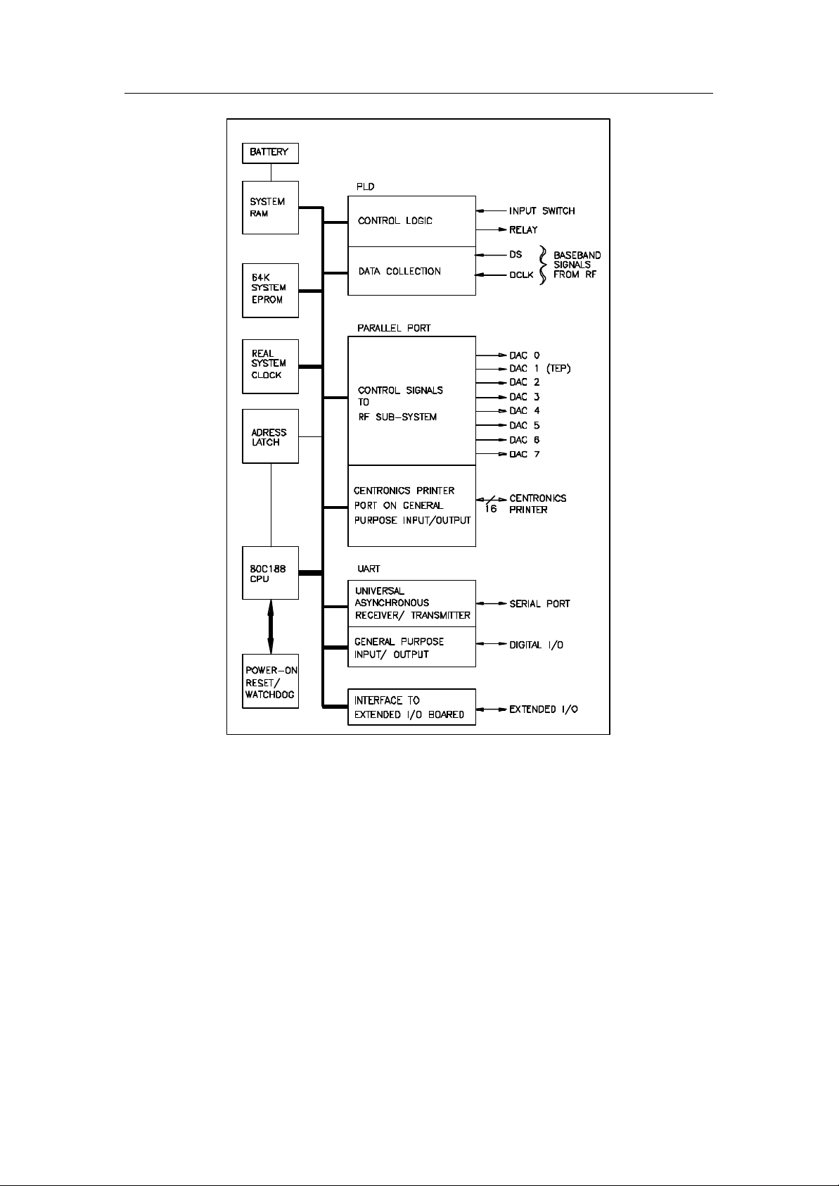
5.4 CPU Section
The L120/L121 CPU system contains the necessary digital logic for the control
of system functions and the decoding of smart label replies under the control of
an 80C188XL embedded controller. In a standard configuration, the CPU sets
up two way system communications via RS232 on serial port O. This port can be
configured for a range of baud rates, parity and stop bits. Unless otherwise
specified, this port is configured as:
• 9600 bits per second
• No parity
• Eight bits per character
• One stop bit.
A functional block diagram of the board is shown in Figure 7 and a brief
description of important blocks follows.
In GemWave L12/L121 systems, the coupler default settings are stored in the 50
bytes of RAM available on the battery back Real Time Clock (RTC). Hence a
real time clock is available as standard on this system.
Some standard features of this board include:
• A parallel port which is available for use as either unbuffered
digital I/O or as a Centronics printer port.
GEMPLUS COMPANY CONFIDENTIAL Page 13
C220 Chips & L120/L121 Couplers - Technical Description
Version 1.0
Figure 7: Functional block diagram of a GemWave L120/L121 CPU system
5.4.1 System Watchdog
The 'watchdog' can be used to trap software 'hanging' and also protects the
128k system RAM in the event of a power failure. It does this by switching the
RAM to an on-board lithium battery until power is restored.
5.4.2 Data Collection Sub-System
GEMPLUS COMPANY CONFIDENTIAL Page 14

C220 Chips & L120/L121 Couplers - Technical Description
Version 1.0
The demodulated smart label replies are fed as TTL level signals to the data
collection system. When the PLD has new label information a system interrupt
process is used to copy the data into the CPU.
5.4.3 Application specific options
The following options are available on the main board at the time of manufacture.
• A de-bounced input switch connected to a CPU interrupt.
• A SPDT Relay.
• Two digital input and three buffered digital output bits are
available for user specification.
The CPU may also be fitted with one of two additional boards to assist for
special function operation:
Extended I/O
• Point to point RS422 or RS485 Communications
• RS232 with full modem control
• Parallel port for additional I/O, which can also implement
Centronics Printer Port.
• 2 additional buffered Output bits
• 2 additional buffered Input bits
• Extra 8 way DIP Switch for User Inputs
Network Card
• Serial Port 0: RS232 3 wire for Coupler Communications
• Serial Port 1: RS422 or RS485 Multi-drop Communications
with RTS / CTS available, or RS232 with full modem control
• additional 8 way DIP Switches for User Selections
• Real Time Clock for time-stamping other timing duties
5.4.4 Communications Interface
GEMPLUS can implement the following protocols as standard options. User
specified protocols are available on request.
• RS232 (3 wire)
• RS232 Full Modem
• RS422 Point to Point
• RS422 Point to Point with RTS / CTS
• RS422 Multi-drop ( 4 wire )
GEMPLUS COMPANY CONFIDENTIAL Page 15

C220 Chips & L120/L121 Couplers - Technical Description
Version 1.0
• RS422 Multi-drop with RTS / CTS
• RS485 Multi-drop ( 2 wire )
• Wiegand
• Centronics Printer Port
• Relay Logic Outputs
• Phone Line Modems
5.5 Power Supply
The standard power supply is a 16 watt linear supply capable of providing the
transceiver with the require regulated +12V supply.
1
128 bits when the tag is in long mode, 72 bits when in short mode.
2
While at least one fully integrated UHF tag is available, the performance is far poorer than tags with
even just a couple of external components.
3
Note that in short mode this is reduced to 40.
GEMPLUS COMPANY CONFIDENTIAL Page 16

DRAFT ONLY
SUBJECT TO CHANGE
V3.06 SOFTWARE
GemWave
TM
MEDIO L120/MEDIO L121
Protocol Guide
Version 3.06
GEMPLUS
June 2000
Revision Date Written by Verify by Validated by
3.01 March 2000
3.05 05 May 2000 Alfio. R. Grasso
3.06 02 June 2000 Alfio R. Grasso
© GEMPLUS 2000 1/34

1. OBJECTIVE ........................................................................................................................................................4
2. COMMAND HIERARCHY ............................................................................................................................4
2.1 SERIAL COMMUNICATION.............................................................................................................................4
2.2 COMMAND FORMAT .......................................................................................................................................4
2.2.1 Checksum calculation...........................................................................................................................4
2.2.2 Checksum Example:..............................................................................................................................5
2.3 DIALOG MODES...............................................................................................................................................5
3. COMMANDS......................................................................................................................................................6
3.1 READ COMMANDS..........................................................................................................................................6
3.2 PROGRAM COMMANDS..................................................................................................................................7
3.3 CONFIGURATION COMMANDS......................................................................................................................8
3.4 ERROR MESSAGES.......................................................................................................................................... 8
4. COMMUNICATION WITH THE READER:...........................................................................................9
4.1 POWER UP S TATE...........................................................................................................................................9
4.2 L121 SYSTEMS -COMPANION MODE AND LOCKED ANTENNAS..............................................................9
4.3 COMPANION MODE......................................................................................................................................10
4.3.1 Single Companion Antenna Mode ....................................................................................................10
4.3.2 Dual Companion Antenna Mode......................................................................................................11
4.3.3 Triple Companion Antenna Mode....................................................................................................11
4.4 LOCKED ANTENNA....................................................................................................................................... 11
4.5 BATTERY BACKUP ....................................................................................................................................... 12
Input Switch Period.......................................................................................................................................12
4.6 STATUS BITS ON THE LABEL......................................................................................................................12
4.7 COMMAND EXECUTION...............................................................................................................................13
5.1 INPUT S WITCH...............................................................................................................................................14
5.2 RESPONSE FORMAT TO READ COMMANDS................................................................................................14
5.3 READ COMMANDS........................................................................................................................................15
5.3.1 High Speed, Continuous Wave, Sorted Read ‘B’............................................................................15
5.3.2 High Speed, Pulsed, Sorted, Multiplexed Read ‘H’.......................................................................15
5.3.3 High speed, Pulsed, Unsorted, Multiplexed Read ‘K’ ...................................................................16
5.3.4 Low Speed, Pulsed, Sorted, Multiplexed Read ‘M’........................................................................16
5.3.5 Low Power Pulsed, Sorted Unique Read ‘U’..................................................................................18
5.3.6 High Speed, Pulsed, Sorted, Status Bits Read (‘?’) :.....................................................................18
5.4 PROGRAM COMMANDS................................................................................................................................20
5.4.1 Verification in all Program Commands...........................................................................................20
5.4.2. Alternate Specification of the Status Bits.......................................................................................20
5.4.3 Program Data Entry Schemes...........................................................................................................20
5.4.4 Program the lower half ‘1’ .................................................................................................................21
5.4.5 Program the upper half ‘2’................................................................................................................22
5.4.6 Program ALL Fields ‘P’....................................................................................................................23
5.4.7 Program Status Bits ‘S’......................................................................................................................24
5.4.8 Program the Security Bit (EAS), conditional ‘T’............................................................................24
5.5 CONFIGURATION COMMANDS....................................................................................................................25
5.5.1 Configure the Serial Port Program ‘C’...........................................................................................25
5.5.2 Set All Application Parameters to Default Values ‘D‘..................................................................26
5.5.3 Exhibit Application Settings ‘E’........................................................................................................27
5.5.4 Frequency of Label Reply Rate (Label Time Out)‘F’....................................................................27
5.5.5 GTA Menu ‘G’ or ‘g’...........................................................................................................................28
5.5.6 Configure the Input Switch ‘I’...........................................................................................................28
5.5.7 Quit ‘q’ or ‘Q’......................................................................................................................................29
5.5.8 Relay Function ‘R’...............................................................................................................................30
5.5.9 What am I (‘W’) :.................................................................................................................................30
5.5.10 Easy Command Mode (‘EASY’) :....................................................................................................31
5.6 INVALID COMMAND.....................................................................................................................................31
6.0 REFERENCE.................................................................................................................................................32
6.1 COMMANDS...................................................................................................................................................32
© GEMPLUS 2000 2/34

6.2 ERROR MESSAGES........................................................................................................................................ 33
6.2.1 Syntax Error.........................................................................................................................................33
6.2.2 Check Sum Error ..................................................................................................................................33
6.2.3 Invalid Data Error ...............................................................................................................................33
6.2.4 Lower Half Locked with different data Error.................................................................................33
6.2.5 Lower Half Locked Error...................................................................................................................33
6.2.6 Verify Error...........................................................................................................................................33
6.2.7 Can’t read Label Error ......................................................................................................................33
6.2.8 Multiple Labels Error.........................................................................................................................34
6.2.9 Invalid Command Error.....................................................................................................................34
6.2.10 Unknown Error..................................................................................................................................34
© GEMPLUS 2000 3/34

1. Objective
This application provides a common interface for all Gemplus Tag applications, for
L120/121 readers.
This application is designed to be used in-conjunction with an application program,
written by Gemplus VAR’s, and running on a PC, under Windows 95/98 or NT.
However, a human readable interface is available under the GTA interface, which can
be used with Hyper Terminal under Windows 95/98/NT or terminal under Windows
3.1.
2. Command Hierarchy
2.1 Serial Communication.
There is one serial port, set to RS232 serial communication. This port can be
configured as detailed in section 5.5.1. The factory settings and the default in the
event of battery corruption are configured to be 9600 Baud, No Parity, 8 Data bits, 1
stop bit and no flow control. If the parameters stored in battery backed RAM are
forgotten by the user, entering the ESC key during the first second after power up,
will force the serial port settings back to the default. Hence, under normal operation
no command should be issued to the reader during the first 1 second after power up.
Additionally, to facilitate easy mode interaction with the user, for debugging
purposes, or code development, the user can enter EASY mode see section 5.5.10, by
entering the ‘?’ character during the first second after power on.
2.2 Command format
Commands and responses format :
<STX> <MESSAGE> <ETX> <CHK>
1 byte variable 1 byte 2 bytes
where <STX> ASCII code for STX (02 Hex)
<ETX> ASCII code for ETX (03 Hex)
<MESSAGE> A variable length message, containing the command
and any parameters. They are separated with comma.
<CHK> These 8 bits are transmitted as 2 ASCII characters
<CHK High> and <CHK Low>,
As the ETX character is used as an escape character under some operating systems,
the ETX character can be replaced with the ETB (17 Hex) for any command. If the
ETB character is used, then all responses from the reader will use the terminating
character ETB instead of ETX, until a new command is issued with the ETX
character. For clarity, the rest of this document will use ETX.
2.2.1 Checksum calculation
The checksum represents the 8 bit exclusive OR of all the characters of the message
and including the STX and ETX. These 8 bits are transmitted as 2 ASCII characters
<CHK High> and <CHK Low>. Each character represents the hexadecimal value of
the 4 bits of each nibble with the most significant nibble transmitted first, and upper
case characters to represent values greater than 9.
© GEMPLUS 2000 4/34

2.2.2 Checksum Example:
GTA MENU
Suppose the user enters the string <STX>EASY<ETX>0F.
The checksum is set to zero, and the first character <STX> (02 in Hex) is “exclusive
ored” with the checksum (00 in Hex) to give a new checksum (02 in Hex). This is
represented as 00 ^ 02 = 02. If we repeat this for every character between the <STX>
and <ETX> characters we get the following sequence.
02 ^ 45 = 47
47 ^ 41 = 06
06 ^ 53 = 55
55 ^ 59 = 0C
0C ^ 03 = 0F
At the end we get the final checksum which is 0F, and hence the command is
accepted.
All commands and responses, except the ESC command during the first 3 seconds,
respect this format.
All commands are in upper case, with the exception of the g and q commands, which
can be in either case.
For clarity only the message field is documented in the following sections of this text.
All commands and responses have an <STX> pre-pended and an <ETX>, <CHK
High> and <CHK Low> appended to the message field.
2.3 Dialog modes
There are 2 ways to control the reader :
§ The secured command protocol, described in this document,
§ The GTA menu with basic commands, described in the document gta_ext.doc
Specific commands are used to change mode.
POWER UP MODE ([command],ESC,?)
<STX>Q<ETX>50
IDLE MODE
<STX>G<ETX>46Q
Where 50 and 46 are the 2 ASCII characters of the check sum<CHK High> and
<CHK Low>, of the string <STX>Q<ETX> and <STX>G<ETX> respectively.
© GEMPLUS 2000 5/34
Frame in ASCII Hexadecimal Comments
<STX>Q<ETX><CHK high><CHK Low> 02 51 03 35 30. Checksum in ASCII 50
<STX>G<ETX><CHK high><CHK Low> 02 47 03 34 36. Checksum in ASCII 46

3. Commands.
High Speed, Pulsed, Unsorted, Multiplexed
All commands in this section, and their responses are of the form
<STX> <MESSAGE> <ETX> <CHK>
1 byte variable 1 byte 2 bytes
For example to set all application parameters the command string and its response is:
Command String
<STX>D<ETX>45 : ASCII CODES (HEXADECIMAL) 02 44 03 34 35
Response String
<STX>OK<ETX>05 ASCII CODES (HEXADECIMAL) 02 4F 4B 03 30 35
Most commands require additional data, and this data is comma delimited. If a
command does not specify a response, then the message of such a response is OK.
Once a command has executed, the reader waits for additional user commands. No
command prompt is issued. Only the message field is described in the command
descriptions below.
Note : ASCII codes
Character Hexadecimal Control Equivalent
STX 02 ^B
ETX 03 ^C
The commands are in 3 groups. Group one is used to read labels, group 2 is used to
program labels, while group 3 is used to configure the reader. There are 21 commands
in the Command set, which consists of the following:
3.1 Read Commands
Command Section Example Description
B 5.3.1 <STX>B<ETX>43High Speed, Continuous Wave, Sorted Read
H 5.3.2 <STX>H<ETX>49High Speed, Pulsed, Sorted, Multiplexed Read
K 5.3.3 <STX>K<ETX>
4A
M 5.3.4 <STX>M,300<E
Read
Low Speed, Pulsed, Sorted Multiplexed Read
TX>53
U 5.3.5 <STX>U<ETX>54Low Power, Pulsed, Sorted, Unique Read
? 5.3.6 <STX>?<ETX>3EHigh Speed, Pulsed, Sorted, Status Bits Read
All read commands, other than ‘?’ have an optional parameter, which is the format of
the response, see section 5.2. In addition, the M command has an additional optional
parameter, which is the dwell time, see section 5.3.4.
The type of system and the functionality of the label determine the speed of reading.
For example, on a multiplexed L121 system, and in the presence of multiple labels in
the RF field, Low Speed-reading is mandatory to read multiple labels.
© GEMPLUS 2000 6/34

Continuous Wave RF is used on high-speed systems, and must be used only with
L120 systems, or L121 systems with antenna 1 locked.
Pulsed RF is used on high speed, low speed, single and multiple antenna systems. All
RF off times are 180 us. The table below details the RF pulse on time parameter for
each pulsed read command, H,K,M,U,?. In the table below CW refers to Continuous
Wave and TEP ON and GRT refer to internal system parameters, defined within the
GTA menu, which have the default values of 15 ms and 100 ms respectively. Also,
the value of the on time for the M command can be over-ridden by a command option.
Command Single
Antenna
Multiple
Antenna
H TEP ON TEP ON
K CW GRT
M GRT GRT
U TEP
ON,GRT
Not
applicable
? GRT GRT
Sorted reads means that the reader only report labels read that have not been
previously reported. The sort buffer is 16 deep. The system and application
parameter Label Time Out can be used to reset the sorter periodically. Unsorted
reading is when the sorter is bypassed, and all labels successfully decoded will be
reported.
The read range of the C220 label is greater than the program range. A low power read
is at the RF power level, in read mode, that will enable a label, positioned at the
maximum program range, to be correctly programmed at full Power. This low power
MUST be adjusted on site, to suit the target tags, the reader antenna and the
environment, please refer to L120 commissioning documentation.
3.2 Program Commands
Command Section Example Description
1 5.4.4 <STX>1,45
Program the Lower Half
6<ETX>2B
2 5.4.5 <STX>2,12
Program the Upper Half
3<ETX>2F
P 5.4.6 <STX>P,12
Program the Label with 123,456 and status T
3,456,T<ET
X>2E
S 5.4.7 <STX>S,F<
Program one or more Status Bits
ETX>38
T 5.4.8 <STX>T,1<
Program the Security Bit, conditional
ETX>48
All these commands have parameters.
© GEMPLUS 2000 7/34

3.3 Configuration Commands
Frequency of Label Reply Rates (Label Time
Command Section Example Description
C 5.5.1 <STX>C,D
Configure the Serial Port
EFAULT<E
TX>25
D 5.5.2 <STX>D<E
Set all Parameters to Default Values
TX>45
E 5.5.3 <STX>E<E
Exhibit Application Settings
TX>44
F 5.5.4 <STX>F,2<
ETX>59
G 5.5.5 <STX>G<E
Out)
Access the GTA Menu
TX>46
I 5.5.6 <STX>I,1,1
Configure Input Switch
00,1000,0<E
TX>79
Q 5.5.7 <STX>Q<E
Quit
TX>50
R 5.5.8 <STX>R,A,
Relay Function
300<ETX>2
1
W 5.5.9 <STX>W<E
What am I
TX>56
EASY 5.5.10 <STX>EAS
Easy Command Mode
Y<ETX>0F
3.4 Error Messages.
CONDITION
RESPONSE
Syntax Error detected in the command message 01
Check Sum Error in the command message 02
Invalid Data in the command message 03
Cannot Program, as the Label lower half is locked with other data 04
Lower Half LOCKED 05
Verify Error (data read after program different to data required) 06
Label cannot be read, to set un-allocated label fields. 07
Multiple Labels detected during a read 08
Invalid Command, unrecognised command 09
See Section 6.2 for details on error messages.
© GEMPLUS 2000 8/34

4. Communication with the reader:
4.1 Power Up State.
After initial power on, the reader executes the previous start up mode command,
executed prior to turning the power off, from the previous session. This command is
stored in battery backed RAM. In the event of battery failure, the read command will
be K mode, unsorted continuous wave (pulsed if more than 1 antenna on an L121
systems).
Prior to reading and reporting labels, the reader responds with the following message
to indicate which command it is using to read labels:
<command> [<,format>] [,<theft>] [,<period >]
1 byte 2 bytes 2 bytes variable
Where
<command> is one of either B,H,K,M, U, or T
<format> is one of either D,H or A, present if a read command
<theft> is one of either 0 or 1, present if the command was T
<period> is present only if the read command was M.
Note: If the T command was last used, the theft state reported in <theft> above, will
be used to program tags, and will also be reported in the message above.
Note: If the M command was last used, with a period parameter, that period parameter
is used, the period will also be reported in the message above.
If the “? Command” was last used, this is not recorded in battery backed RAM, and
the previous start up mode command will still be stored.
Reading and reporting, or Theft programming and reporting continues until the exit
sequence (quit command), 5.5.7 is received.
4.2 L121 Systems -Companion Mode and Locked Antennas
The purpose of the companion mode is both to save time, and decrease the user’s
involvement with the architecture of the reading system. Both 3D and 2D antenna
systems are employed by RF/ID companies to read planar labels in a 2D or 3D
environment. The fact that 3 antennas are required to read a planar label in all 3
dimensions should not be a concern of the user. All the user needs to know is that a
label was read, the actual orthogonal antennas that read the labels is of no
consequence.
© GEMPLUS 2000 9/34

4.3 Companion Mode
For L121 systems multiple antennas can be considered as a single antenna for
reporting purposes. For example, in a 3D portal system, a read point consists of 3
orthogonal antennas, placed such that the label can be in any orientation when it goes
through the RF field. For many applications, it is not important which of the 3
antennas read the label, and so the concept of companion antennas was developed,
which associates the 3 antennas as one antenna and then reports the label, with the
companion antenna number, rather than the antenna number. For other applications,
such as a doorway portal, 2 antennas are associated with the read point. Hence
companion mode can be single, dual or triple.
If the companion mode is set to either dual or triple, and a label is read on one of the
antennas in the companion set then the next RF pulse will occur on the first antenna of
the next companion set. For example, antenna count is set to 8, and companion mode
is set to dual, and the label is read on antenna 3, then next RF pulse will be on antenna
5, ie antenna 4 is skipped. Another example is, if antenna count is set to 6, companion
mode is set to triple and the label is read on antenna 2, then the next RF pulse will be
on antenna 4.
In the above, the 3D portal antenna is used to read the label, which may be entering
the antenna’s field in any orientation. The 3D portal consists of 3 separate antenna, as
can be seen by the three cables. If a label is read on any of the three antennas, it may
not be important to the user to know which one of the three antennas read the label,
only that the label was read. Hence, the user would define companion mode to triple.
4.3.1 Single Companion Antenna Mode
Antenna Companion Antenna
1 1
2 2
3 3
4 4
5 5
6 6
7 7
8 8
© GEMPLUS 2000 10/ 34

4.3.2 Dual Companion Antenna Mode
Antenna Companion Antenna
1 1
2 1
3 2
4 2
5 3
6 3
7 4
8 4
If the antenna count is not even, then the last companion set will only have one
antenna, for example antenna count is set to 7, then companion set 4 will have only
one antenna, antenna 8.
4.3.3 Triple Companion Antenna Mode
Antenna Companion Antenna
1 1
2 1
3 1
4 2
5 2
6 2
7 3
8 3
If the antenna count is not a multiple of 3, then the last companion set will have less
than 3 antenna, for example in the table above companion antenna set 3 has only 2
antennas, antennas 7 and 8.
4.4 Locked Antenna
It is also possible to have an L121 system, but lock all RF activity to one antenna.
This may be the case when demonstration equipment is being used, and the customer
may have purchased an L121 with multiple antennas, but now wants to evaluate the
L120 performance. Using a parameter locked antenna does this. Any antenna can be
locked (1 to 8). If no antennas are to be locked, then locked antenna is set to 0.
© GEMPLUS 2000 11/ 34

4.5 Battery Backup
This application uses the battery backed RAM to store application parameters. In the
event of battery backup these parameters will be set to the following:
Parameter Default Value
Last Read Command K
M Command Period 300 ms
Label Time Out 10 seconds
Relay Mode Automatic
Relay Period 300 ms
Input Switch Type 0
Input Switch Delay 100 ms
Input Switch Period 1000 ms
Input Switch Mode 0
Output Format Decimal
Baud rate 9600
Parity None
Data Bits 8
Stop Bits 1
Antenna Count 1
Companion Mode 1
Locked Antenna 1
Terminator ETX
Theft State 1 (set)
Trace Disabled
The antenna count, locked antenna number, companion mode and trace are system
parameters and can only be changed by the GTA menu.
4.6 Status Bits on the Label.
In most programming commands, the default label status bits are used in
programming the label. The obvious exceptions are when programming the theft bit,
and locking the label. Once a label has been locked, it cannot be unlocked.
Status bit Description Default
Program Speed Status The setting of the Speed Status bit,
Normal
programmed into the label, either normal
or fast.
Program Theft Status The setting of the Theft Status bit,
Set
programmed into the label, either set or
cleared
Program Length Status The setting of the Length Status bit,
Long
programmed into the label, either long or
short.
Program Lock Status The setting of the Locked Status bits,
Unlocked
programmed into the label, either locked
or unlocked.
© GEMPLUS 2000 12/ 34

4.7 Command Execution.
In most applications, a read command will be executing to read label. All of the
Configuration Commands, with the exception of the G command, can be issued at any
time while the reader is executing read command. These commands if received may
alter the nature of the current read command, for example if the input switch is
enabled to type 1, a read cycle will not begin, unless the input switch is activated.
If the G command, read commands, or program commands are received, then an error
message will be issued.
© GEMPLUS 2000 13/ 34

5. List of Commands
5.1 Input Switch.
Each reading command can be controlled by an external input switch, which may
interrupt the normal operation of the reader to carry out a pre-defined action.
There are 3 modes of operation of the input switch. The first mode (type 0) is to
disable the input switch. The second mode (type 1) is to delay RF reading of labels
until an interrupt occurs, while the third mode (type 2) is used to delay reporting of
labels which have been read and which are stored in a buffer.
The input switch is described in sections 5.5.6 below. For the sake of clarity in this
document, the effect of the input switch is not documented in the text of the read
commands, but it is still active.
If the input switch Type is 0, then reading and reporting are immediate.
If the input Switch Type is 1, then no read activity will begin until the interrupt is
received, and the appropriate delay has expired.
If the Input Switch Type is 2, then no output messages will be issued until the
interrupt is received.
Reading and subsequent reporting may also be terminated if the Input Switch Type is
1, and the period timer has expired.
5.2 Response format to read commands.
When a read command is active, and a response message is to contain a label reply.,
the message response in the following format:-
<ant>, <upper>, <lower>
2 bytes Variable variable
Where
<ant> : the companion antenna number (1 to 8) used to read the label
<lower> , <upper> ,the label contents, in the specified format, with leading zeros
suppressed, and if the label length is short, the upper field is set to 0.
The Output Formats are :
§ D for Decimal,
§ H for Hexadecimal,
§ A for alphanumeric.
The format of the reply is set to decimal by default.
However, the user can override the output format, by an optional command line
parameter. The output format is stored in battery backed RAM, so that upon start up,
it can be applied. However, this memory value is overridden, if the user specifies
another output format, used for any read command.
If the output format is alphanumeric, then the label data is interpreted as up to 6
alphanumeric characters stored in the lower half, and up to 5 alphanumeric characters
stored in the upper half.
© GEMPLUS 2000 14/ 34

Character set :
§ upper case (A..Z),
§ lower case (a..z),
§ numerical (0..9),
§ SPACE
Each alphanumeric character is stored as a 6-bit character (64 combinations). Hence
4 bits are not used in the lower half (D36, D37, D38, D39) and 3 bits are not used in
the upper half (D70, D71, D72).
5.3 Read Commands
The reader responds with the OK response message when a read command is issued,
to indicate that the read command is executing.
Reading and reporting continues until the exit sequence 5.5.7 is received.
Upon exiting the command the reader responds with the OK response message, to
indicate that the command has stopped. The antenna number is not reported in the OK
message.
To use an alternative output format, the user can issue the read command with an
optional parameter.
<read command> [,<format>]
1 byte 2 bytes
Where
<read command> is the read command identifier ( B,H, K, U, M, ?) . See below for
details.
<format> is optional and is one of either D,H or A. If the format is not present in the
command line, then it will default to Decimal. There is no format specifier for the
read status command (‘?’), the format is always decimal.
5.3.1 High Speed, Continuous Wave, Sorted Read ‘B’.
For this command to be executed, L121 systems must have the antenna locked to 1.
Label time Out is used to determine if a label previously read and reported is to be re-
reported.
Application Example Read B Command
This command is useful in library applications, at the book return chute, where for
example, more than one book may be placed in the return chute, and high speed
Continuous Wave operation is mandatory to capture all labels moving quickly in the
confined field of the book chute. The number of labels in the chute should be limited
to 5, if a larger population of labels need to be identified, then the chute should not be
used, but the labels kept stationery in the RF field for a period of 1 to 2 seconds.
It is for this reason that L121 systems, with an antennas count greater than 1, should
NOT BE used for book return chute applications, unless the antenna is locked to 1 and
the book chute antenna is physically connected to that antenna.
5.3.2 High Speed, Pulsed, Sorted, Multiplexed Read ‘H’.
This command is used on L121 systems to enable a reading system with multiple
antennas to read labels, which may be travelling at relatively high speed. The
assumption in this command is that only one label will be in the field at a time, but
that label will only be in the field for a limited time period.
© GEMPLUS 2000 15/ 34

As the label’s orientation with respect to the antenna(s) cannot be pre-determined, a
number of antennas in orthogonal planes are used to read the label. The RF is on each
antenna for a limited period of time, before the RF is switch onto the next antenna.
As soon as a label is read on an antenna, the RF is immediately switch to the next
antenna, in order to capture another label, which may be just entering the field.
Hence, the anti-collision capability of the C220 label is not activated because the RF
is switched, quickly.
Reading and reporting continues until the exit sequence 5.5.7 is received. Label time
Out is used to determine if a label previously read and reported is to be re-reported.
Companion mode and locked antenna parameters are used to determine which
antennas are energised, as described in 4.2, 4.3, 4.4.
Application Example Read H Command
This command could be used in a library application at the library staff counter
reader. Here the operator, “The Librarian” has been trained in the use of the RF/ID
equipment and understands the parameters of each command, and will NOT place
more than one label in the RF field. Where as the general library user, may not use the
equipment correctly, and an alternative command ‘U’ at 5.3.5 has been provided, for
the general user.
Another example is the use of the 3D portal on a high-speed conveyor belt system. In
this application the label’s orientation is not known. Since the label (only one in the
field) is travelling at high speed, high speed RF switching between the 3 orthogonal
antennas is required to reliably read the label.
5.3.3 High speed, Pulsed, Unsorted, Multiplexed Read ‘K’
This command is similar to the ‘B’ read command (5.3.1) above, except that all labels
read are reported, regardless of Label Time Out. In L121 systems, companion mode
and locked antenna parameters are used to determine which antennas are energised, as
described in 4.2, 4.3, 4.4.
Application Example Read K Command
This command could be used when the same label can be reported to the host, more
than once, in fact, every time the reader successfully reads the label. This can be used
to determine if the label is still in the field.
5.3.4 Low Speed, Pulsed, Sorted, Multiplexed Read ‘M’
This command is used on L121 systems to enable a reading system with multiple
antennas to read labels, which may be travelling at a slow speed. The assumption in
this command is that more than one label will be in the field at a time, but that those
labels will be in the field for a period of time, sufficient to read labels, exploiting the
C220 Anti-collision scheme, which is about 300 ms per antenna used. For example if
a 3D field is used, consisting of 3 multiplexed antennas, then the labels should be
guaranteed to be in the reading field for at least 900 ms.
As the label’s orientation with respect to the antenna(s) cannot be pre-determined, a
number of antennas in orthogonal planes are used to read the label. The RF is on each
antenna for a period of time, controlled by an internal timer. This internal timer is
known as the General Response Time in the GTA menu.
© GEMPLUS 2000 16/ 34

However, as indicated above, 300 ms is an optimum time for multiple labels in a 3D
portal application. Hence, this command has an optional parameter called the dwell
period, which is from 100 to 500 ms, and is used to change this period for M
commands. The period is also stored in battery backed RAM, in case the M command
was the last command issued, before power down, and hence will be the read
command executed at power on.
Changing the General Response time in the GTA menu will have the effect of
lengthening the program sequence, and this is not desirable. The RF is not switched,
until the expiration of this internal timer. If the optional parameter is not present, then
the General Response Time is used.
For example to issue the M command with a period of 300 ms, the command string
will be M,300
Reading and reporting continues until the exit sequence 5.5.7 is received. Label time
Out is used to determine if a label previously read and reported is to be re-reported.
Companion mode and locked antenna parameters are used to determine which
antennas are energised, as described in 4.2, 4.3, 4.4. However, the use of a locked
antenna defeats the purpose of this command.
The Command Format is :
M, [,period] [,<format>]
2 bytes 4 bytes
2 bytes
100 to 500ms
Where <period> and <format> are optional, and can be in any order.
<period> can be in the range 100 to 500 ms and
<format> is defined in section 5.3.
Application Example Read M Command
This command could be used in a laundry application, where multiple articles of
clothing may pass through an antenna system. Such antenna system could consist of
multiple individual antennas for two reasons. The first is that the volume of space
required for reading is large, and consequently more than one antenna is needed to
read the labels. Secondly, the label’s orientation cannot be pre-determined, and hence
2D or 3D RF fields are required. The key parameter is the time the labels are in the
RF field. This time should be at least 300 ms per antenna, so for example if 4
antennas are required, then the labels should be in the field of those antennas for 1.2
seconds. The maximum number of labels simultaneously in the field should be
limited to less than 10.
© GEMPLUS 2000 17/ 34

5.3.5 Low Power Pulsed, Sorted Unique Read ‘U’.
2 bytes
This command is only valid on L120 systems, or L121 systems that are LOCKED to
antenna 1.This command starts pulsed interrogation. This read is at a RF Power,
which reads labels at the distance, that full RF power will successfully program a
label. Naturally, this feature is dependent upon the type (size and form factor) of tag
being programmed, and the antenna connected to the reader. Hence, each reader will
need site adjustment, please refer to reader documentation for adjustment procedures.
Two pulses are initiated, the first pulse uses TEP ON time (usually 15ms), while the
second pulse is on for GRT (usually 100ms). If one and only one label is read in both
pulses, and it is the same tag in both pulses, and it is different to the last 16 labels
reported, or if label time out has expired, then that label is reported in a response
message. This above process continues until the quit command 5.5.7 is received.
Application Example Read U Command
This command can be used at a library self check out borrowing station. In this
application it is mandatory to ensure that one and only one label is in the field. The
‘U’ command can be used to search for labels that may be accidentally programmed,
if a program cycle were to be initiated.
5.3.6 High Speed, Pulsed, Sorted, Status Bits Read (‘?’) :
The reader responds with the OK response message, to indicate that the Read ‘?’
command is executing. This command is used to report the status bits of a label. This
command starts pulsed interrogation, but at normal RF power. If a label is read, and it
is different to the last 16 labels reported, or if label time out has expired, then that
label status bits are reported in a response message. Companion mode and locked
antenna parameters are used to determine which antennas are energised, as described
in 4.2, 4.3, 4.4.
The response message will be:
<ant>, <tag response> <Lock>, <Length>, <Speed>, <Security>
as per 5.2 above
Variable, but
only in decimal
2 bytes
X LOCKED
U UNLOCKED
2 bytes
L LONG
S SHORT
2 bytes
F FAST
N NORMAL
1 byte
T THEFT ON
O THEFT OFF
format.
Where :
<ant> is the companion antenna, only present if antenna count is greater than 1
<Lock> is X for LOCKED or U for UNLOCKED
<Length> is L for LONG or S for SHORT
<Speed> is F for FAST or N for NORMAL
<Security> is T for THEFT ON or O for THEFT OFF
This above process continues until the quit command 5.5.7 is received
Upon exiting the command the reader responds with the OK response message, to
indicate that the command has stopped.
© GEMPLUS 2000 18/ 34

5.3.7 Read Command Example.
In this example let us assume that the Input Switch Type is 0 (label reading and
reporting is immediate) and the label is read on antenna 1. If the K command is
issued, and there is one tag in the field, and the tag is programmed with contents
123,456 the dialogue between the user (commands) and the reader (response
messages) will be as follows;
Commands Responses Comments
<STX>K<ETX>4A Read tag fields in decimal
<STX>OK<ETX>05 Acknowledge of K command
<STX>1,123,456<ETX>37 tag contents are sent in decimal
<STX>1,123,456<ETX>37 tag contents are sent in decimal
<STX>1,123,456<ETX>37 tag contents are sent in decimal
<STX>1,123,456<ETX>37 tag contents are sent in decimal
<STX>Q<ETX>50 Exit read
<STX>OK<ETX>05 Acknowledge of Q command
<STX>K,H<ETX>2E Read tag fields in hex
<STX>OK<ETX>05 tag contents are sent in hex
<STX>1,7B,1C8<ETX>0F tag contents are sent in hex
<STX>1,7B,1C8<ETX>0F tag contents are sent in hex
<STX>1,7B,1C8<ETX>0F tag contents are sent in hex
<STX>Q<ETX>50 Exit read
<STX>OK<ETX>05 Acknowledge of Q command
<STX>K,A<ETX>27 Read tag fields in alphanumeric
<STX>OK<ETX>05 Read tag fields in alphanumeric
<STX>1,0001X,000078<ET
X>66
<STX>1,0001X,000078<ET
X>66
<STX>1,0001X,000078<ET
X>66
<STX>1,0001X,000078<ET
X>66
tag contents are sent in
alphanumeric
tag contents are sent in
alphanumeric
tag contents are sent in
alphanumeric
tag contents are sent in
alphanumeric
<STX>Q<ETX>50 Exit read
<STX>OK<ETX>05 Acknowledge of Q command
© GEMPLUS 2000 19/ 34

5.4 Program Commands
5.4.1 Verification in all Program Commands.
All program commands contain a program sequence followed by a read, to verify that
the label has been correctly programmed.
5.4.2. Alternate Specification of the Status Bits.
It is also possible to specify alternative status bits, to use in all programming
commands, rather than use the default status bits. These status bits can be specified in
any order, using the single characters as specified below.
Status Bit Set Cleared
Locked X (Locked) U (Unlocked)
Length L (Long) S (Short)
Speed F (Fast) N (Normal)
Theft T (Theft On) O (Theft Off)
If conflicting status bit combinations are specified an error message will be issued. If
one or more status bits are not specified then the default value for that status bit will
be used.
5.4.3 Program Data Entry Schemes.
Data to be programmed can be entered in one of three ways. The first method is to
use a decimal representation of the data to be programmed; the second way is to use a
hexadecimal representation, while the third is to store alphanumeric characters.
The first 2 methods result in optimum use of the label’s memory, and give flexibility
to the application developer, as the interpretation of the bits stored in the tag memory
can be left to the developer. In this fashion the label is just used to store 40 bits of
data in the lower half (D0 to D39) and 33 bits of data in the upper half (D40 to D72).
The third method is non-optimum and restricts the developer to storing and retrieving
alphanumeric Data.
Character set :
§ upper case (A..Z),
§ lower case (a..z),
§ numerical (0..9),
§ SPACE
Each alphanumeric character is stored as a 6-bit character (64 combinations). Hence
4 bits are not used in the lower half (D36, D37, D38, D39) and 3 bits are not used in
the upper half (D70, D71, D72).
© GEMPLUS 2000 20/ 34

5.4.4 Program the lower half ‘1’
Alphanumeric
up to 6 alpha-numeric characters (upper and lower
This command is used to program the lower half of the label data.
Command format :
1, <lower> [,<format>] [,<status bits>]
2 bytes Variable 2 bytes variable
where :
<lower> the label data,
Valid numbers
Decimal Hexadecimal
Lower 40 bits 1,099,511,627,775 FFFFFFFFFF
<format> specify the format of the label data
Format Value Label data
Decimal D Decimal value, leading zeros suppressed
Hexadecimal H Hexadecimal value, upper case characters only
A
case)
<status bits> is the status bits as specified in 5.4.2.
Examples
(1) To program a label with the number 123 in decimal, the message will be 1,123.
(2) To program the label with 123 hexadecimal, the message will be 1,123,H.
(3) To specify that the label status bit Speed to be set to Fast, the command 1,123,F
will program the label with the status bit set to Fast, while all other status bits will be
set to the default values.
(4) To program a label with a string, the message will be 1,string,A
(5) To program a label with StRiNg and status bits set to LOCKED the message will
be 1,StRiNg,A,X
If the status bit length is set to Long, then the label is read to extract the upper half. If
the label cannot be read, then an error message will be issued.
If the length is set to Short, no programming of the upper half will take place.
For L121 systems, all programming is either performed on the locked antenna, or if
the antennas are unlocked on antenna 1. The number of antenna logically connected
to the L121 and the locked antenna status are can only be altered within the GTA
menu.
If the program and verify was successful, then the OK message response is issued,
otherwise an error message is issued.
© GEMPLUS 2000 21/ 34

5.4.5 Program the upper half ‘2’
Alphanumeric
up to 5 alpha-numeric characters (upper and lower
This command is used to program the upper half of the label data.
Command format :
2, <upper> [,<format>] [,<status bits>]
2 bytes Variable 2 bytes variable
where :
<upper> the label data,
Valid numbers Decimal Hexadecimal
Upper 33 bits 8,589,934,591 1FFFFFFFF
<format> specify the format of the label data
Format Value Label data
Decimal D Decimal value, leading zeros suppressed
Hexadecimal H Hexadecimal value, upper case characters only
A
case)
<status bits> is the status bits as specified in 5.4.2.
Examples
(1) To program a label with the number 123 in decimal, the message will be 2,123.
(2) To program the label with 123 hexadecimal, the message will be 2,123,H.
(3) To specify that the label status bit Speed to be set to Fast, the command 2,123,F
will program the label with the status bit set to Fast, while all other status bits will be
set to the default values.
(4) To program a label with a string, the message will be 2,string,A
(5) To program a label with StRiNg and status bits set to LOCKED the message will
be 2,StRiNg,A,X
If the status bit length is set to Short, and error message will be issued. The label is
read to extract the lower half. If the label cannot be read, then an error message will
be issued.
For L121 systems, all programming is either performed on the locked antenna, or if
the antennas are unlocked on antenna 1. The number of antenna logically connected
to the L121 and the locked antenna status are can only be altered within the GTA
menu.
If the program and verify was successful, then the OK message response is issued,
otherwise an error message is issued.
© GEMPLUS 2000 22/ 34

5.4.6 Program ALL Fields ‘P’
upper label data :up to 5 alpha-numeric characters
lower label data :up to 6 alpha-numeric characters
This command is used to program all sections of the C220 EEPROM.
Command format :
P, <upper>, <lower> [,format>] [,status bits>]
2 bytes variable variable 2 bytes variable
where :
<upper> the upper label data,
Valid numbers Decimal Hexadecimal
Upper 33 bits 8,589,934,591 1FFFFFFFF
<lower> the lower label data,
Valid numbers Decimal Hexadecimal
Lower 40 bits 1,099,511,627,775 FFFFFFFFFF
<format> specify the format of the label data
format Value Label data
decimal D Decimal value, leading zeros suppressed
hexadecimal H Hexadecimal value, upper case characters only
alphanumeric A
(upper and lower case)
(upper and lower case)
<status bits> is the status bits as specified in 5.4.2
Examples :
To program a label with the number 123 (upper half) and 456 (lower half) in decimal,
the command message will be P,123,456. However to program the label with 987
(upper) ABC (lower) hexadecimal, the command message will be P,987,ABC,H.
Similarly, as in 5.4.21 above, the status bits can be overridden.
In order to specify that the label status bit Speed to be set to Fast, the command
P,123,456,F will program the label with the status bit set to Fast, while all other status
bits will be set to the default values.
To program sections of the C220 memory, sections can be omitted. For example to
program the upper half with the number 123, the command would be P,123,, The ,,
indicates that the lower half is to be left. Any missing fields are extracted from the
label prior to programming, and in this example the lower half will be programmed
with the same data that was in the label, prior to the program command executing.
Similarly to program the lower half the command would be P,,123,H,X,F This will
leave the upper half alone, and lock the tag, setting the speed to fast, and the upper
half to 123 Hexadecimal. Similarly, any missing status bits, will be set to the default
status bits.
To lock a tag the command would be P,,,L, or to set the theft bit the command would
be P,,,T.
If the length is specified to be short, no programming of the upper half will take place.
Similarly, if the user specifies alphanumeric data for the tag data, then the format
must be set to A.
© GEMPLUS 2000 23/ 34

For L121 systems, all programming is either performed on the locked antenna, or if
2 bytes
the antennas are unlocked on antenna 1. The number of antenna logically connected
to the L121 and the locked antenna status are can only be altered within the GTA
menu.
If the program and verify was successful, then the OK message response is issued,
otherwise an error message is issued.
5.4.7 Program Status Bits ‘S’
This command is used to program the 4 status bits of the C220 EEPROM.
Command format :
S, <status bits> [,<status bits>]
2 bytes 1 byte variable
where
<status bits> are as specified below. and may be one or more of the following:
Status Bit Set Cleared
Locked X (Locked) U (Unlocked)
Length L (Long) S (Short)
Speed F (Fast) N (Normal)
Theft T (Theft On) O (Theft Off)
If the length is specified to be short, no programming of the upper half will take place.
For L121 systems, all programming is either performed on the locked antenna, or if
the antennas are unlocked on antenna 1. The number of antenna logically connected
to the L121 and the locked antenna status are can only be altered within the GTA
menu.
If the program and verify was successful, then the OK message response is issued,
otherwise an error message is issued.
5.4.8 Program the Security Bit (EAS), conditional ‘T’
Command format :
T, <EAS bit>
1 byte
<EAS bit>=0 : to turn the security bit off
<EAS bit>=1 to set the theft bit to “ON”.
This is a special programming command, which is used to arm and disarm the security
bit, if and only if one label has been detected in the RF program field.
This command is only valid on L120 systems, or L121 systems that are LOCKED to
antenna 1.
This command starts pulsed interrogation. This read is at a RF Power, which reads
labels at the distance, that full RF power will successfully program a label. Naturally,
this feature is dependent upon the type (size and form factor) of tag being
programmed, and the antenna connected to the reader. Hence, each reader will need
site adjustment, please refer to reader documentation for adjustment procedures.
© GEMPLUS 2000 24/ 34

Two pulses are initiated, the first pulse uses TEP ON time (usually 15ms), while the
<PARITY>,
N=NONE,
O=ODD,
second pulse is on for GRT (usually 100ms). If one and only one label is read in each
pulse, and the label read is the same in each pulse, and it is different to the last 16
labels reported, then that label is programmed with the specified “theft status”, and
then the label is reported. If more than one label is read in either pulse, or only one
pulse reads the label, or different labels are read in each pulse, then an error is issued.
If no labels are read in either pulse, then the cycle is re-started.
This above process continues until the quit command 5.5.7 is received
5.5 Configuration Commands
5.5.1 Configure the Serial Port Program ‘C’
This command sets the communication port of the reader.
Command format :
C, <BAUD RATE>, <DATA BITS>,
2 bytes Variable
2 bytes 2 bytes
<STOP BITS>
2 bytes
2400,
4800,
9600,
E=EVEN
19200,
DEFAULT
where
<BAUD RATE> is either 2400,4800,9600, 19200 or DEFAULT
<DATA BITS> is 7 or 8
<PARITY> is N,O, or E where N=NONE, O=ODD, E=EVEN
<STOP BITS> is 1 or 2
If the BAUD RATE field is not DEFAULT, all fields are required. If all the fields are
correctly parsed the reader’s response message OK is issued at the current settings and
then the reader is set to the new Serial Port Parameters. An error message is issued if
any error condition is detected.
If the BAUD RATE field is DEFAULT and the other fields are absent, then the reader
will respond with the response OK and then set the RS 232 parameters to 9600,N,8,1.
© GEMPLUS 2000 25/ 34

5.5.2 Set All Application Parameters to Default Values ‘D‘
This Command resets the reader to the power up state, defined below
Command format :
D
1 byte
Default values are :
Parameter Default
Communications 9600,8,N,1
Locked Antenna 1
Label Time Out 10 seconds
Input Switch Type 1
Delay 100 ms
Period 1000 ms
Mode 0
Relay Mode A (Automatic)
Relay Time 300 milliseconds
Read Mode K
Read Commands Output Format Decimal
Read M Command Period 300 milliseconds
Theft Command 1 (set)
Terminator ETX
Trace Disabled
If the command is successful, the reader responds with OK at the old serial port
settings. Then the reader changes the serial port to the new settings, and stores all
parameters in battery backed RAM.
Note: Although, there is no command in the application command set to change the
locked antenna status, this command will set it to 1, just in case the user inadvertently
set the locked status in the GTA menu, to an alternative. Similarly, there is no
command to enable TRACE in the application command set, but the user can enter the
GTA menu, to toggle trace on, and then quit back to the application command set.
© GEMPLUS 2000 26/ 34

5.5.3 Exhibit Application Settings ‘E’.
Command format :
E
1 byte
This command responds with the message:
<BAUD>, <DATA>, <PARITY>, <STOP>, <TIME>, <TYPE>, <DELAY>, <PERIOD>,
Variable 2 bytes 2 bytes 2 bytes variable 2 bytes variable variable
Continues :
<MODE>, <RELAY>, <RTIME>, <COMMAND>, <MPERIOD>,<FORMAT>, <THEFT>
2 bytes 2 bytes variable 2 bytes variable 2 bytes 1 byte
where
<BAUD> is either 2400,4800,9600 or 19200
<DATA> is 7 or 8
<PARITY> is N,O, or E where N=NONE,O=ODD,E=EVEN
<STOP> is 1 or 2
<TIME> is Label Time Out a value between 0 and 32,767
<TYPE> is the type of input switch 0,1 or 2
<DELAY> is the delay after input 0 to 1000 milliseconds
<PERIOD> is the period of RF activation, 1 to 32767 milliseconds
<MODE> is the mode or label reading (0,1)
<RELAY> is the mode of relay operation (auto or manual)
<RTIME> is the time the relay will be closed in auto mode
<COMMAND> is the start up command (B,H,K,M,U,T).
<MPERIOD> is the period used for the M command
<FORMAT> is the read command output format
(D=Decimal, H=Hexadecimal, A=Alphanumeric)
<THEFT> is the default theft bit to program in the T command
5.5.4 Frequency of Label Reply Rate (Label Time Out)‘F’.
This command is used to set the reply rate of label reports with the same number. It
has the same function as label time out in the GTA interface.
Command format :
F, <label timeout>
2 bytes Variable
Where
<label timeout>, a value for the label time Out in seconds, between 0 and 32766, or
the special value of 32767.
If the value is set to 0, all labels read will be reported in the response format,
regardless of any previous reports.
If the value is 32767, then this is a special setting that prevents the timer from
expiring and any labels reported would not be reported again, until the 16 deep Label
Buffer in the reader is full.
The reader responds with the OK message to signify that the command was properly
executed.
© GEMPLUS 2000 27/ 34

5.5.5 GTA Menu ‘G’ or ‘g’
This command is used to access the GTA menu. The GTA menu is described in the
GTA menu guide, and does not conform to the above message structure.
Command format :
<STX>G<ETX><CHK high><CHK Low>
5.5.6 Configure the Input Switch ‘I’
This command is used to configure the functionality of the input switch. Each reading
command can be controlled by an external input switch, which may interrupt the
normal operation of the reader to carry out a pre-defined action.
Command format :
I, [<type>] [,<delay>,<period>,<mode>]
2 bytes 1 byte Variable
where the definitions of these fields is contained below.
The <type>, <delay>, <period> and <mode> are battery backed parameters, and in the
event of battery backup failure, they will be set to :
Type 0
Delay 100 milliseconds
Period 1000 milliseconds
Mode 0 (normal read command operation)
Note: Although type 0 does not use the other parameters, they need to be set in battery
backed RAM for consistency!
For example a valid command string would be I,1,100,1000,0
NOTE: Use of the input switch can result in messages being issued from the
reader, without a corresponding command issued from the host.
This command, does not result in a read cycle, a separate read command, or
activation of the input switch, is required in order to start reading labels. This
command only configures the functionality of the reader in response to the input
switch.
If the input switch command is successfully executed the OK response message is
issued.
Note : the effect of the input switch is not documented in the text of the read
commands, but it is still active.
© GEMPLUS 2000 28/ 34

5.5.6.1 Input Switch Types
to begin reading of
labels after the switch
report the label held in
Input Switch Type Label reading Label reporting Comments
0 Immediate Immediate ignore the input switch
1 Waits for Input Immediate
has been activated
2 Immediate Waits for Input
the buffer
5.5.6.2 No activity for the Input Switch (type 0)
If the type is set to 0, and the other parameters are missing, then the input switch is
ignored, and Label reading will start immediately a read command is issued, and
Label reporting will occur as soon as a label is read, decoded and sorted.
5.5.6.3 Triggered reading (type 1)
If the type is set to 1, then the input switch is used to trigger reading activity. The
parameter <delay> is the period in milliseconds, from 0 to 1000, in which after receipt
of the input switch signal, the RF is activated for label reading.
NOTE: The input switch signal must be received, in order for the RF to be activated.
The parameter <period> is the period in milliseconds, from 1 to 32,767, for which the
RF is enabled, after the initial delay. The RF can terminate earlier by receipt of the
“quit command” 5.5.7, or by the mode parameter. The parameter <mode> is used to
select the read mode.
If the mode is 1, as soon as a label is read, it is reported with the response format, the
RF is then disabled and the command terminates. This command in effect reads one
label.
If the mode is 0, all labels read, sorted, and reported in a message response, according
to the rules of the associated read command. For example if the mode is K, all labels
read are reported, regardless of the sorter and label time out.
In both modes (0,1), if no labels are read, and the period timer expires, the reader will
respond with the OK response, to signify that the command has terminated.
5.5.6.4 Triggered reporting Mode (type 2)
If the type is set to 2, and the other parameters are missing, then all reading
commands, as specified in 5.3 do not report label readings, but store the most recently
read label in a buffer. When the input switch is activated, the buffer contents are
immediately reported in a response message.
If there is no valid label in the buffer, the null response <ant>,0,0 is issued, for all
read label commands. As soon as the label has been transmitted, the buffer is cleared.
5.5.7 Quit ‘q’ or ‘Q’
This command is used to terminate reading commands. If this command is issued at
the top level, no response message is issued. If the command is issued while a read
command was executing, the reader will issue the OK response.
Command format :
© GEMPLUS 2000 29/ 34
Q
1 byte

5.5.8 Relay Function ‘R’
This command is used to close or open the relay. The command message has the
following format:
Command format :
R, <mode>, <period>
2 bytes 2 bytes
O open,
C close,
A automatic
Variable
In automatic mode : 0 to
32767 ms
0 : automatic mode is disabled
Where
<mode> is O for open, or C for close, or A for automatic.
<period> is optional for both the O and C modes, but if present it must be valid.
Under automatic mode, the period, a value from 0 to 32767, in milliseconds will be
used to close the relay when a label is read and reported. If another label is read while
the relay is closed, the period will be reset. If the period is set to 0, then automatic
mode is disabled, and the modes O and C can be used to manually control the relay.
The mode and period parameters are battery backed, and in the event of battery
failure, the mode will default to automatic and the period will default to 300
milliseconds.
The reader will respond with the OK message if the command was successfully
executed
For example to set the relay to automatic mode for 500 milliseconds, the command
string will be R,A,500
5.5.9 What am I (‘W’) :
This command is used to report the interface name and version in the following
format:
Command format :
W
1 byte
Response format :
Medio L120/121 GT Interface Version X.YY.
Where X is from 1 to 9, and YY is from 00 to 99.
© GEMPLUS 2000 30/ 34

5.5.10 Easy Command Mode (‘EASY’) :
This application is to be used with a host PC, and where it is easy for the PC to
assemble a command string, and calculate the Check Sum. However, for Human
interaction, Check Sum calculation is difficult.
To facilitate human interaction, this command is used to toggle a flag, that disables
(or enables) the requirement to insert the <STX> and <ETX> characters in a
command string, and supply the Check Sum. The user then only needs to specify the
commands and their parameters, and the reader assumes that the check sum and
<STX> and <ETX> characters were present. The user terminates each command by
the <CR> carriage return character.
Each time the string EASY is in a command string, it will toggle the flag, and enable
or disable the Check Sum checking. EASY mode is always OFF when the unit is first
powered on, unless the ‘?’ character is entered in the first second, after power on.
The command string for easy mode is
Command format :
<STX>EASY<ETX>0F
8 bytes
Any user input is echoed. When the user terminates the command by the <CR>, the
reader responds with a <CR> (carriage return, 0D in hexadecimal) and <LF> (line
feed, 0A in hexadecimal), to indicate that the command has been entered.
The reader will still respond with <STX> <ETX> messages, and insert a <CR> and
<LF> between messages for easy interpretation.
Response format
<STX><MESSAGE><ETX><CR><LF>
5.6 Invalid Command.
If a command is received that is not one of the above, or if a command is received that
is not allowed, then error messages 09 will be issued. Commands that are not allowed
are reading or programming commands while a read command is executing, or the
Read B command on an L121 system that does not have antenna 1 locked.
© GEMPLUS 2000 31/ 34

6.0 Reference.
Frequency of Label Reply Rates (Label Time
6.1 Commands
Command Section Example Description
B 5.3.1 <STX>B<ETX>43High Speed, Continuous Wave, Sorted Read
H 5.3. 2 <STX>H<ETX>49High Speed, Pulsed, Sorted, Multiplexed Read
K 5.3.3 <STX>K<ETX>4AHigh Speed, Pulsed, Unsorted, Multiplexed Read
M 5.3.4 <STX>M,300<ET
Low Speed, Pulsed, Sorted Multiplexed Read
X>53
U 5.3.5 <STX>U<ETX>54Low Power, Pulsed, Sorted, Unique Read
? 5.3.6 <STX>?<ETX>3EHigh Speed, Pulsed, Sorted, Status Bits Read
1 5.4.4 <STX>1,456<ET
Program Lower Half
X>2B
2 5.4.5 <STX>2,123<ET
Program Upper half
X>2F
P 5.4.6 <STX>P,123,456,
Program the Label with 123,456 and status T
T<ETX>2E
S 5.4.7 <STX>S,F<ETX>38Program Status Bits
T 5.4.8 <STX>T,1<ETX>48Program the Security Bit, conditional
C 5.5.1 <STX>C,DEFAU
Configure the Serial Port
LT<ETX>25
D 5.5.2 <STX>D<ETX>45Set all Parameters to Default Values
E 5.5.3 <STX>E<ETX>44Exhibit Application Settings
F 5.5.4 <STX>F,2<ETX>
59
Out)
G 5.5.5 <STX>G<ETX>46Access the GTA Menu
I 5.5.6 <STX>I,1,100,10
00,0<ETX>79
Q 5.5.7 <STX>Q<ETX>50Quit
R 5.5.8 <STX>R,A,300<
ETX>21
W 5.5.9 <STX>W<ETX>56What am I
EASY 5.5.10 <STX>EASY<ET
X>0F
© GEMPLUS 2000 32/ 34
Configure Input Switch
Relay Function
Easy Command Mode

6.2 Error Messages
CONDITION
RESPONSE
Syntax Error detected in the command message 01
Check Sum Error in the command message 02
Invalid Data in the command message 03
Cannot Program, as the Label lower half is locked with other data 04
Lower Half LOCKED 05
Verify Error (data read after program different to data required) 06
Label cannot be read, to set un-allocated label fields. 07
Multiple Labels detected during a read 08
Invalid Command, unrecognised command 09
6.2.1 Syntax Error
Error message 1 is issued when a command is received and that command requires
parameters, but the parameters as specified in the command do not follow the defined
syntax of that command. For example, if the lower half parameter was missing from
the P command.
6.2.2 Check Sum Error
Error message 2 is issued when a command string is received and the received check
sum and the command don’t match.
6.2.3 Invalid Data Error
Error message 3 is issued upon receipt of a command string that contains data that is
not within the valid range as specified by the command.
This error message is also issued when the B read command is issued on a L121
system, with more than one antenna enabled, and if the antenna is not locked to
antenna 1.
6.2.4 Lower Half Locked with different data Error
Error message 4 is issued when a program command is received and that specifies a
lower half content, but the lower half content is locked and is different to that
specified by the user.
6.2.5 Lower Half Locked Error
Error message 5 is issued when a program lock command is issued to a label that is
already locked.
6.2.6 Verify Error
Error message 6 is issued when a program command detects that the label just
programmed, and subsequently read to verify the programming cycle, responds with a
reply that is different to that specified in the command.
6.2.7 Can’t read Label Error
Error message 7 is issued when a program command, that does not specify the label
content in full, is issued, but the reader cannot read a label response to fill in the
© GEMPLUS 2000 33/ 34

missing fields. For example, to lock the label, the read must first read the label, to
determine at least the lower half, and then program the lower half, together with the
lock code. If the reader fails to read the lower half, then the error message is issued.
6.2.8 Multiple Labels Error
Error message 8 is issued when a multiple labels are detected in the conditional
program command (T) or in the read command (U).
6.2.9 Invalid Command Error
Error message 9 is issued when a command is received that is not valid in the current
context. For example if a read command is received, before the current read command
is terminated.
6.2.10 Unknown Error
Error messages 10 to 29, and 99 are issued when the reader detects an internal fault.
If these errors are ever received, then the user should generate a report. Such a report
should outline the command executing and what other activities may have been
occurring in the vicinity of the reader.
© GEMPLUS 2000 34/ 34

MEDIO L120 FUSE SELECTION
The L120 IEC connector allows for multiple voltage selection, 110V, 220V and 240V.
To select the appropriate voltage, follow these steps.
On the IEC connector located at the bottom right hand side of the unit, the fuse holder
and selector must be removed.
To do so use a small flat blade screwdriver and push the
tabs towards the inside of the IEC connector. (Fig. 1) As
each tab is pushed, it should click out of the locked
position. The fuse holder can then be removed (Fig. 2).
Fig. 1. Push tabs where
arrows indicate.
Fig. 2. Fuse Holder
The voltage selector (grey plastic insert, Fig. 3.)
110
220
240
contained in the fuse holder is to be removed. This
selector rotates to show the appropriate voltage in the
holder’s cutout window. Rotate the selector until
appropriate voltage shown and re-insert into holder.
Insert appropriate fuse and replace assembly into
Fig. 3. Voltage selector IEC connector.
Ensure that appropriate type and rating of fuse is used.
220/240VAC-50Hz - Fuse 250V T 250mA
100/110VAC-60Hz - Fuse 250V T 500mA
CAUTION: For continued protection against the risk of fire,
replace only the same type and rating of fuse.
Gemplus Tag Australia Pty. Ltd.
1st Floor – 99 Frome Street – Adelaide
PO Box 99 – Rundle Mall – SA – 5000 – AUSTRALIA
ACN 008 031 945 Inc in South Australia – Internet: http://www.gemplus.com

MEDIO L120 FCC EQUIPMENT STATEMENT
NOTE: This equipment has been tested and found to comply with the limits for a Class B
digital device, pursuant to Part 15 of the FCC Rules. These limits are designed to
provide reasonable protection against harmful interference in a residential installation.
This equipment generates, uses and can radiate radio frequency energy and, if not
installed and used in accordance with the instructions, may cause harmful
interference to radio communications. However, there is no guarantee that
interference will not occur in a particular installation. If this equipment does cause
harmful interference to radio or television reception, which can be determined by
turning the equipment off and on, the user is encouraged to try to correct the
interference by one or more of the following measures:
- Reorient or relocate the receiving antenna.
- Increase the separation between the equipment and receiver.
- Connect the equipment into an outlet on a circuit different from that to which
the receiver is connected.
- Consult the dealer or an experienced radio/TV technician for help
Gemplus Tag Australia Pty. Ltd.
1st Floor – 99 Frome Street – Adelaide
PO Box 99 – Rundle Mall – SA – 5000 – AUSTRALIA
ACN 008 031 945 Inc in South Australia – Internet: http://www.gemplus.com
 Loading...