

Page 1
Author
Franck D’ANNUNZIO
Date 10/04
/2019
Object
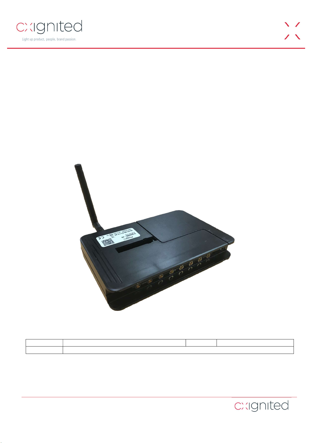
User’s Guide
HSPN V2.0
Power Node Reader V2
User's Guide
Revision 3.2
www.cxignited.com
Copyright © cxignited.com
This document and the information it contains are the exclusive property of CXIgnited.
All rights reserved. Any unauthorized reproduction is strictly prohibited. CXIgnited is a registered trademark.
75, Boulevard Haussmann
75008 Paris
France
Page 2

Publishing Information
Disclaimer and Limitation of Liability
All information herein is either public information or is the property of and owned solely by CXIgnited-TAGSYS who shall have and keep the
sole right to file patent applications or any other kind of intellectual property protection in connection with such information.
Nothing herein shall be construed as implying or granting to you any rights, by license, grant or otherwise, under any intellectual and/or
industrial property rights of or concerning any of’ information.
This document can be used for informational, non-commercial, internal and personal use only provided that:
The copyright notice below, the confidentiality and proprietary legend and this full warning notice appear in all copies.
This document shall not be posted on any network computer or broadcast in any media and no modification of any part of this
document shall be made.
Use for any other purpose is expressly prohibited and may result in severe civil and criminal liabilities.
The information contained in this document is provided “AS IS” without any warranty of any kind. Unless otherwise expressly agreed in writing,
CXIGNITED makes no warranty as to the value or accuracy of information contained herein. The document could include technical inaccuracies
or typographical errors. Changes are periodically added to the information herein.
Furthermore, CXIGNITED reserves the right to make any change or improvement in the specifications data, information, and the like described
herein, at any time.
Therefore, CXIGNITED assumes no liability and is not responsible for customer applications or product or software which includes
CXIGNITED products.
CXIGNITED HEREBY DISCLAIMS ALL WARRANTIES AND CONDITIONS WITH REGARD TO THE INFORMATION CONTAINED
HEREIN, INCLUDING ALL IMPLIED WARRANTIES OF MERCHANTABILITY, FITNESS FOR A PARTICULAR PURPOSE, TITLE AND NONINFRINGEMENT. IN NO EVENT SHALL CXIGNITED BE LIABLE, WHETHER IN CONTRACT, TORT OR OTHERWISE, FOR ANY
INDIRECT, SPECIAL OR CONSEQUENTIAL DAMAGES OR ANY DAMAGES WHATSOEVER INCLUDING BUT NOT LIMITED TO
DAMAGES RESULTING FROM LOSS OF USE, DATA, PROFITS, REVENUES, OR CUSTOMERS, ARISING OUT OF OR IN CONNECTION
WITH THE USE OR PERFORMANCE OF INFORMATION CONTAINED IN THIS DOCUMENT.
CXIGNITED does not and shall not warrant that this product/system/equipment will be resistant to all possible attacks, and shall not incur,
and disclaims, any liability in this respect. Even if each product is compliant with current security standards in force on the date of their design,
security mechanisms' resistance necessarily evolves according to the state-of-the-art in security and notably under the emergence of new
attacks. Under no circumstances shall CXIGNITED be held liable for any third-party actions, and in particular in case of any successful attack
against systems or equipment incorporating CXIGNITED products.
CXIGNITED disclaims any liability with respect to security for direct, indirect, incidental or consequential damages that result from any use of
its products. It is further stressed that independent testing and verification by the person using the product is particularly encouraged, especially
in any application in which defective, incorrect, or insecure functioning could result in damage to persons or property, denial of service, or loss
of privacy.
All CXIGNITED products are subject to careful quality control throughout the manufacturing process and are warranted to be of merchantable
quality and free from manufacturing defects. Published information concerning CXIGNITED products are based upon research which the
Company believes to be reliable, but such information does not constitute a warranty. Because of the variety of possible uses for CXIGNITED
products and the continuing development of new uses, the purchaser should carefully consider the fitness and performance of the product for
each intended use and the purchaser assumes all risks in connection with such use. Seller shall not be liable for damages in excess of the
purchase price of the product or for incidental or consequential damages. All specifications are subject to change without prior notice.
© 2000-2019 CXIGNITED SAS. All rights reserved.
All trademarks and registered trademarks are the property of their respective owners.
2/33 Revision 3.2 07/03/2019
Page 3

Power Node Reader V2 User's Guide
Printed in France.
CXIGNITED (TAGSYS RFID) – 286 avenue du Pastre F-13400 AUBAGNE (France)
Tel: +33 (0)4 42 18 89 00 / Fax: +33 (0)4 42 18 89 01
Document Reference: DOC16599A2
3/33 Revision 3.2 07/03/2019
Page 4
Symbol
Meaning
Read This First
Welcome to the CXIGNITED. This User's Guide is designed to help you get up and running quickly using this high-quality Radio
Frequency Identification (RFID) system. It describes all you need to know about how to install and use the CXIGNITED system and
its associated applications.
This guide is designed for all CIT (Certified Integrators by CXIGNITED) and for CXIGNITED Expert Network customers
implementing a low-cost and high-performance RFID solution.
This document does not assume any previous knowledge of Radio Frequency Identification (RFID) technology.
Conventions
CAUTION: A note that advises users that a specific action could result in the loss of data or damage the
hardware.
WARNING: A note that advises users that a specific action may result in physical harm.
A note that provides additional information that helps the user performing a task or obtaining the best
performance from the product.
If you need assistance
Please contact your nearest CXIGNITED Sales Representative or the CXIGNITED Welcome Desk at:
Telephone: +33 (0)4 42 18 89 00
Fax: +33 (0)4 42 18 89 01
E-Mail: info@cxignited.com
Website: http://www.cxignited.com
Contact for Comments
We welcome your feedback to help us provide high quality documentation.
For technical comments, please contact our Welcome Desk:
Telephone: +33 (0)4 42 18 89 00
Fax: +33 (0)4 42 18 89 01
E-Mail: info@cxignited.com
Please remember to quote the Document Reference Number DOC16594A0, your job title and your company.
4/33 Revision 3.2 07/03/2019
Page 5

Power Node Reader V2 User's Guide
Quality Issues
CXIGNITED implements stringent quality controls at all stages of its manufacturing process. However, should you find a defect with
this product, please notify your CXIGNITED Quality Service representative using the dedicated Product Return Form.
Telephone: +33 (0)4 42 18 89 00
E-Mail: rma@cxignited.com
5/33 Revision 3.2 07/03/2019
Page 6

Power Node Reader V2 User's Guide
TABLE OF CONTENT
PUBLISHING INFORMATION ________________________________________________________ 2
DISCLAIMER AND LIMITATION OF LIABILITY _______________________________________________ 2
READ THIS FIRST ____________________________________________________________________ 4
CONVENTIONS ________________________________________________________________________ 4
IF YOU NEED ASSISTANCE _______________________________________________________________ 4
CONTACT FOR COMMENTS _____________________________________________________________ 4
QUALITY ISSUES _______________________________________________________________________ 5
1 FOR YOUR SAFETY _______________________________________________________________ 9
1.1 GENERAL USE ____________________________________________________________________ 9
1.2 CARE AND MAINTENANCE _________________________________________________________ 9
1.3 SAFETY INFORMATION ___________________________________________________________ 10
1.3.1 OPERATING ENVIRONMENT _________________________________________________________ 10
1.3.2 OPERATING CONDITIONS __________________________________________________________ 10
1.3.3 BATTERIES ______________________________________________________________________ 10
2 CERTIFICATION ________________________________________________________________ 11
2.1 REGULATORY NOTICES FOR OPERATION IN THE US __________________________________ 11
2.2 REGULATORY NOTICES FOR OPERATION IN THE EU AND DOC _________________________ 13
2.3 ELECTRICAL SAFETY _____________________________________________________________ 14
2.4 ROHS (RESTRICTION OF THE USES OF CERTAIN HAZARDOUS SUBSTANCES) _____________ 14
2.5 WEEE (WASTE ELECTRICAL AND ELECTRONIC EQUIPMENT) __________________________ 14
3 POWER NODE READER DESCRIPTION __________________________________________ 15
3.1 DELIVERY PACK _________________________________________________________________ 15
4 POWER NODE READER COMMUNICATION INTERFACES ________________________ 17
4.1 POWER NODE PARTS _____________________________________________________________ 17
4.2 POWER NODE ANTENNA CLUSTERS ________________________________________________ 18
5 POWER NODE READER INSTALLATION AND OPERATION ______________________ 21
5.1 POWER NODE INSTALLATION _____________________________________________________ 21
5.1.1 INSTALLATION BEST PRACTICES SUMMARY _______________________________________________ 23
5.2 POWER NODE CONFIGURATION SOFTWARE ________________________________________ 24
6 ENVIRONMENTAL AND MECHANICAL DATA ___________________________________ 29
7 TROUBLESHOOTING ___________________________________________________________ 30
6/33 Revision 3.2 07/03/2019
Page 7

Power Node Reader V2 User's Guide
8 WARRANTY CONDITIONS ______________________________________________________ 31
8.1 WARRANTY _____________________________________________________________________ 31
8.2 WARRANTY EXCLUSIONS _________________________________________________________ 31
8.2.1 GENERAL PROVISIONS _____________________________________________________________ 31
8.2.2 HOW TO RETURN DEFECTIVE PRODUCTS_______________________________________________ 32
7/33 Revision 3.2 07/03/2019
Page 8

Power Node Reader V2 User's Guide
TABLE OF FIGURES
Figure 1: Power Node Radio Part........................................................................................................................................................... 16
Figure 2 : Battery and Power Supply Pack ............................................................................................................................................ 16
Figure 3 : Connectors’ cover ................................................................................................................................................................... 16
Figure 4 : Power Node Notch Cover .................................................................................................................................................... 16
Figure 5 : Power node Reader dismantled ........................................................................................................................................... 17
Figure 6 : Patch Antenna in its casing ..................................................................................................................................................... 19
Figure 7 : Bow Tie Dipole Antenna ........................................................................................................................................................ 20
Figure 8 : Bow-Tie Dipole Dimensions ................................................................................................................................................. 20
Figure 9 : Power Node Standing Up right with integral antenna vertical ..................................................................................... 21
Figure 10 : Plastic Stand to position the Power Node Reader in Upright Position ................................................................... 22
Figure 11: Fixture Side Bar Power Node Strap Fixation ................................................................................................................... 22
Figure 12 : Power Node or Antenna Wall fixation ............................................................................................................................ 23
Figure 13 : PN installation best practices .............................................................................................................................................. 23
Figure 14 : Main Windows after entering Hot Spot parameters .................................................................................................... 24
Figure 15 : Main Screen following a Test PN query ........................................................................................................................... 25
Figure 16 : Start of the Read PN sequence with the first PN. ......................................................................................................... 26
Figure 17 : Final Screen after completion of the 2 PN reading cycles ........................................................................................... 27
Figure 18 : HTML result file open in a Window Explorer browser. ............................................................................................. 27
Figure 19 : Log file of all passed commands to HS and PN .............................................................................................................. 28
8/33 Revision 3.2 07/03/2019
Page 9

Power Node Reader V2 User's Guide
1 For Your Safety
1.1 General Use
The Power Node Reader is designed to be reliable and to provide years of trouble-free service. Please observe the following general
tips:
Take care not to scratch the device. Keep the device clean. When working with the device, use only CXIGNITED-approved
accessories.
This device is not waterproof and should not be exposed to rain or moisture. Under extreme conditions, water may enter
the circuitry.
Protect the device from extreme temperatures. For example, do not place the device in a windowed area where the sun
may cause extreme temperatures, and keep it away from heaters and other heat sources.
Do not store or use the device in any location that is extremely dusty, damp, or wet.
Use a soft, damp cloth to clean the device. If the surface of the device becomes soiled, clean it with a soft cloth moistened
with a diluted window-cleaning solution.
1.2 Care and Maintenance
This device is a product of superior design and should be handled with care. The suggestions below will further increase the lifetime
of this device.
Keep the device and all parts and accessories out of the reach of small children.
Keep the device dry. Precipitation, humidity and liquids contain minerals that will corrode electronic circuits.
Do not use or store the device in dusty, dirty areas. Its moving parts can be damaged.
Do not store in hot areas. High temperatures can shorten the life of electronic devices, damage batteries and warp or melt
certain plastics.
Do not store in cold areas. When the device warms up (to its normal temperature), moisture can form inside the device,
which may damage electronic circuit boards.
Do not attempt to open the device. Non-professional handling of the device may damage it.
Handle the device with care. Shocks may break internal circuit boards.
Do not clean the device with harsh chemicals, cleaning solvents or strong detergents. Gently wipe the device with a soft
cloth slightly dampened in a mild soap-and-water solution.
Do not paint the device. Paint may clog the device’s moving parts and prevent proper operation. Paint with metallic contents
may limit device performances.
Do not bend the antenna part or lean on it.
Do not put stress on antenna cables. Avoid bending the antenna cables to a radius of less than 1 inch (2.5 cm).
Do not pull the cables for connecting and disconnecting. Always handle the connectors itself, either with your hands or
with an adapted tool.
If an antenna cable is broken, position the cable such that the broken ends do not touch metal until it has been replaced.
Contact your nearest qualified CXIGNITED representative.
If the device or any accessory are not working properly, take it to your nearest qualified CXIGNITED representative.
Do not attempt to remove or dispose of fitted batteries. Contact your nearest qualified CXIGNITED representative or
contact.
Remove at once any condensation using a dry and clean piece of cloth to prevent corrosion of metallic parts
9/33 Revision 3.2 07/03/2019
Page 10
Power Node Reader V2 User's Guide
1.3 Safety Information
1.3.1 Operating Environment
When connecting the device or any accessory to another device, read its user’s guide for detailed safety instructions. Do not connect
incompatible products.
As with all RF equipment, users are advised that the equipment should only be used in its normal operating position.
This product is designed and tested to withstand normal indoor environmental conditions following the FCC Part 15 guidelines.
Temperature ranging from 0 to 55°C
Humidity level ranging from 40% to 60% Relative Humidity
To insure optimum operating performance the temperature to which the equipment is exposed should be in the range 10°C to 30°C.
1.3.2 Operating Conditions
The Power Node activation time is controlled by the inventory scheduling that is defined by CXIgnited.
Do not change the inventory schedule without prior agreement from CXIgnited.
Under any circumstances, the following operation sequence of the Power Nodes must be respected, otherwise the device may be
damaged and may harm the environment:
Respect a ratio of Power Node activation time and relax time of 1 to 5, i.e. after 10 second activation, wait 50 seconds
before the following activation cycle.
A Power Node must not be activated for more than 2 minutes consecutively and must remain inactive for at least 10
minutes before the following activation.
1.3.3 Batteries
CXIgnited RFID products contain batteries of very specific types and technology. Do not attempt to change them yourself. Public
safety would inevitably put at risk.
Power node can host up to three 2600mAH Lithium Ion batteries.
Do not add or change cells: if a single cell is present leave it that way. At initial system installation, the number of necessary batteries
is carefully assessed per the settings.
If you think capacity is not adequate, please contact CXIgnited support.
WARNING: Do not attempt to open Product Casing to change or dispose of batteries. Contact your
designated CXIgnited designated maintenance and support person.
When handling the battery pack for installation or maintenance, please take care to not short circuit the contacts of the battery back
when touching them with metal objects.
10/33 Revision 3.2 07/03/2019
Page 11

Power Node Reader V2 User's Guide
2 Certification
2.1 Regulatory Notices for operation in the US
An RFID system, typically composed of a Radio Frequency emission device such as the Power Node Reader connected to an antenna,
is subject to local national regulations that may differ by country.
In the present case, the Hot Spot Power Node RFID System has been designed developed and tested to only operate in the USA or
any country allowing FCC certified Radio Modules contained in the present product.
If the Power Node Reader is further integrated in a different product, it is the responsibility of the manufacturer
of this complementary product to obtain the required approvals for this product.
The Power Node Reader has been designed to comply with Part 15 C and B of the FCC Rules for the US version.
It has been Granted an Authorization as a radio and computer peripheral Equipment. The grant of operation is FCC ID is
QHKPNV2CLUSTER. All necessary proofs of conformity, including Grants of Equipment Authorization are available from the FCC
Web site using the FCC ID.
Changes or modifications not expressly approved by CXIgnited could void the user’s authority to operate the
equipment.
This equipment includes an intentional radiator with its FCC ID:
SQGBL652 for the BLE652-SC Low Energy Blue Tooth module connected to an external
antenna FlexPIFA LAIRD part number 001-0022 tested and approved with the present
module.
The Power Node Reader itself, includes the Low Energy Blue Tooth module.
11/33 Revision 3.2 07/03/2019
Page 12

Power Node Reader V2 User's Guide
Power Node Reader QHKPNV2CLUSTER
WARNING TO USERS IN THE UNITED STATES
FEDERAL COMMUNICATIONS COMMISSION (FCC) RADIO
This equipment has been tested and found to comply with the limits for a Class B digital device, pursuant to Part 15 of the FCC
Rules. These limits are designed to provide reasonable protection against harmful interference in a residential installation. This
equipment generates, uses and can radiate radio frequency energy and, if not installed and used in accordance with the instruction,
may cause harmful interference to radio communications. However, there is no guarantee that interference will not occur in a
particular installation. If this equipment does cause harmful interference to radio or television reception which can be determined
by turning the equipment off and on, the user is encouraged to try to correct the interference by one or more of the following
measures:
▪ Reorient or relocate the receiving antenna.
▪ Increase the separation between the equipment and receiver.
▪ Connect the equipment into an outlet on a circuit different to that to which the receiver is connected.
▪ Consult the dealer or an experienced radio/TV technician for help.
12/33 Revision 3.2 07/03/2019
Page 13

Power Node Reader V2 User's Guide
2.2 Regulatory Notices for operation in the EU and DoC
The Power Node Reader has been designed to comply with the EU Radio Equipment Directive. It has been tested by a notified
laboratory in France.
Changes or modifications not expressly approved by CXIgnited could void the user’s authority to operate the
equipment.
13/33 Revision 3.2 07/03/2019
Page 14

Power Node Reader V2 User's Guide
2.3 Electrical Safety
CXIgnited products are Information Technology Equipment. They all follow the IEC60950 standard.
All parts used in the product follow the UL guidance and are UL recognized.
All Power supplies delivered with the HSPN system are UL listed and LPS.
Plastic enclosures are made using the highest safety grades for flammability according the IEC60950 standard.
To insure the highest possible level of safety do not replace our PSU or recommended PoE+ switches by
equivalent ones without LPS and UL marking.
2.4 RoHS (Restriction of the uses of certain Hazardous Substances)
CXIGNITED certifies that this product is compliant with the European Directive 2002/95/EC for the restriction in Electric and
Electronic Equipment (RoHS) of the use of the following hazardous substances:
Lead
Mercury
Cadmium
Hexavalent Chromium
Polybrominated biphenyl flame retardants
Polybrominated diphenyl ether flame retardants
This declaration is based on information provided by our suppliers and subcontractors.
2.5 WEEE (Waste Electrical and Electronic Equipment)
Do not dispose yourself of electronic goods: contact your local CXIgnited correspondent. He will advise you
of the best way to dispose of our products.
This product bears the selective sorting symbol for waste electrical and electronic
equipment (WEEE)
This means that this product must be handled pursuant to European Directive
2002/96/EC in order to be recycled or dismantled to minimize its impact on the
environment.
Do not dispose of your old product in your general household waste bin.
For further information, please contact your local or regional authorities.
14/33 Revision 3.2 07/03/2019
Page 15

Power Node Reader V2 User's Guide
3 Power Node Reader Description
The Power Node Reader is designed to be part of a whole “Hot Spot Power Node” system.
The “Hot Spot Power Node” system is designed to emphasize the range of a RFID reader addressing passive tags. The system uses
UHF frequency band, following the FCC 15.247 standard (including frequency hopping feature), and ISO 18000-6c protocol.
In this system, the Hot Spot, that includes a RFID reader, pilots many Power Nodes through remote links. The Power Nodes are put
close to tags areas, to efficiently energize the tags. The Power node repeats and amplifies the RFID interrogation signal. The Hot
Spot transmits the RFID interrogation and receives the backscattered signal from the passive tags.
The remote link to the Power Nodes and the interrogation signals are not transmitted in the same time intervals.
The Power Node radio receives the Hot Spot, RFID interrogation signal, amplifies it and transmits it to the passive tags.
The Power Node Battery pack has up to three 2400mAH 1850 Lithium Ion Rod type rechargeable batteries.
The number of batteries inserted can vary according to the installation. Usually, when PN are permanently supplied with power from
the USB port inlet, only one battery is fitted.
On the bottom of the battery pack a micro USB connector allows to charge and supply power using a 6 port ANKER A2123 USB
charger.
It takes typically up to 6 hours to fully recharge the 3 batteries in parallel.
To insure the highest possible level of safety do not replace our recommended PSU or by equivalent ones. In
doing so you will also keep the compliance of your system.
A Power Node RFID reader cannot operate on its own.
It needs BLE signals from the Hot Spot V2 to get operation commands and a 2.45GHz analogue signal broadcast to generate its RFID
interrogation signal in the 902-928MHz US band or 866-867MHz EU band.
3.1 Delivery Pack
The power node is delivered with the following parts:
A power node Radio Pack refer to Figure 1
A Battery and Supply Pack Figure 2
A notch cover Figure 4 to easily feed through a Zip-Tie to affix the power node to fixtures side bars
A specific key to unlock and separate the power pack from the Radio feeding it through two holes
A Connectors’ cover Figure 3 to discreetly hide the cables and connectors from the view of customers.
15/33 Revision 3.2 07/03/2019
Page 16

Power Node Reader V2 User's Guide
Figure
3 : Connectors’ cover
Figure
4 : Power Node Notch Cover
Figure 1: Power Node Radio Part
Figure 2 : Battery and Power Supply Pack
Only one universal main Power Supplies is strongly recommended by CXIgnited to fit the Power Node electrical and safety
requirements:
The ANKER 2123 USB charger with six ports available. It is well suited for up to 6 Power Nodes connection.
16/33 Revision 3.2 07/03/2019
Page 17

Power Node Reader V2 User's Guide
4 Power Node Reader Communication
4.1 Power Node Parts
The Power Node Reader has 8 external MCX jack connector’s Antenna ports:
From the Bottom to the top left:
RF Output Port #8
RF Output Port #7
RF Output Port #6
RF Output Port #5
RF Output Port #4
RF Output Port #3
RF Output Port #1
RF Output Port #1
5V0 DC input 2,5 A maximum micro USB socket (bottom left side of Battery Pack)
Interfaces
The Power Node Reader V2 can only to be powered by the recommended Power Supply Units.
Only the USB port is available for powering and charging
The main disconnecting devices for the auxiliary Power Supply Units are their IEC plug Inlets. If personal cannot reach them easily
when placed high up, do make sure the mains plug used can be isolated from a dedicated circuit breaker easily accessible.
Figure 5 shows the Power node dismantled. Left hand side the Radio Part, Right hand side the Integral Battery Pack. Further left the
8 MCX plugs are visible. Battery back should always be placed downwards for optimum integral antenna orientation.
Figure 5 : Power node Reader dismantled
17/33 Revision 3.2 07/03/2019
Page 18

Power Node Reader V2 User's Guide
4.2 Power Node Antenna Clusters
This new generation of distributed RFID interrogators readers can only work with specific set of antennas call clusters for the
Power node optimum operation.
The Power Node Reader V2 915MHz transmit antenna Clusters are supplied by CXIgnited. They have been
designed to efficiently illuminate and interrogate items and tested to be compliant to US and EU ETSI
regulations. They also limit the human exposure to Electromagnetic fields.
Do not connect any other antenna but the one supplied and fitted by CXIGNITED!
Each RF port can supply 4 clusters of 4 antennas without significant loss in performance. Each cluster possesses an MCX RF inlet
from either the PN RF port for the first one of from a cluster. In that case, a specific cable from SMB to MCX must used to daisy
chain the cluster. It is made of LRM195 coaxial cable with losses of 0.4dB/m at 915MHz operating frequency.
Figure 6 shows the cable arrangement supplied by TAGSYS – CXI to connect the first cluster to one of the 8 RF ports available
from the Power Node. The length A ranges from 0.5m to 3m in 0.5m steps.
Figure 7 shows the cable arrangement supplied by TAGSYS – CXI to connect the cluster n nearest to the PN V2 to the cluster
n+1. The lengths available range from 0.5m to 3m in 0.5m steps.
Figure 6: MCX PN V2 RF Port to Cluster Input Port Cable
Figure 7: MCX Cluster n RF Input left to SMB female RF Cluster n-1 RF Output
When connecting the PN V2 RF Port or daisy chaining from a previous cluster make sure to use the low loss
supplied cables by TAGSYS – CXI!
The use of any other type of RF coaxial cables will heavily degrades the system performance
Figure 8 shows inside a typical antenna cluster made of conventional dipoles. It tends to radiate all over the place with a preferred
polarization i.e. communication is optimum when tags and Bow-Tie Dipole longest sides are parallel. Its Bow-Tie radiating element
18/33 Revision 3.2 07/03/2019
Page 19

Power Node Reader V2 User's Guide
makes it less sensitive to close by material. Thus, affixing it to metal parts still allows a reduced range operation despite nonoptimum placement.
On the top part is located an antenna multiplexer with switches setting the number of connected antennas. 1 to 4
The two dipole Antennas, with a gain of 0dBi each
Figure 9 shows inside a 4 antennas clusters as an example.
Standards Clusters are supplied entirely covered up with antennas well protected from external chocs.
They can be placed either inside the furniture when metallic or behind it when wooden.
Figure 8 : Cluster of 2 Dipole Antennas
Another type of cluster of circular patch antennas can be seen on Figure 10.
Beam width is narrower which can be approximated to a cone of 90° angle of operation. There are ideal to fit into metallic shelves
thanks to their reflectors irradiating only forward.
19/33 Revision 3.2 07/03/2019
Page 20

Power Node Reader V2 User's Guide
Figure 9 : Cluster with 4 Bow-Tie Antennas
Clusters come into 3 different widths per type of antennas (Dipole or Patch) including 2, 3 and 4 antennas.
Do make sure to order and fit the best width and type of antennas according to the furniture
material (wood or metal) and its dimensions!
Figure 10 : Cluster 4 antennas fitted with Circular Patch Antennas
Make sure to always use supplied antenna casings! The spacing’s and material have been carefully designed to insure optimum
radiation and avoid interferences with over apparatus.
Never Connect directly an antenna to a Power Node V2 Reader RF Port!
The V2 system can only work if connected to a cluster and its multiplexor board!
20/33 Revision 3.2 07/03/2019
Page 21

Power Node Reader V2 User's Guide
5 Power Node Reader Installation and
Operation
5.1 Power Node Installation
The latest generation of Power Nodes readers has no external antennas nearby. This design allows ease of installation and a
compact design.
Figure 11 : Power Node Standing Up right with integral antenna vertical
Up to 8 RF channels are available to connect to 8 distant and remote 866-867MHz or 902-928MHz antennas using a shielded cable
of up to 5 meters.
During installation, the Power Node Readers should be located high up to easily communicate with the Hot Spot minimizing
interferences and fading caused by customers’ activity on the floor plan.
In a typical store, the Hot Spots are placed in ceiling. Power Nodes readers should be placed in direct line of sight well above the
floor at a minimum of 2-meter height.
For optimum range and read performance, the Power Node Reader 2.45GHz PIFA antennas should be
aligned with the Hot Spot Readers in vertical position, upright. No obstacles should be within the line of sight
of any PN towards one of the 4 sides of the Hot Spot.
The Power Node casing has rectangular openings/notches in the front and rear surfaces. These notches are used to slide the Power
Node onto a plastic stand or mounting plate for placing it on the fixture. If the opening is not used for fixing the Power Node, it shall
be covered with the appropriate Power Node Notch Cover.
21/33 Revision 3.2 07/03/2019
Page 22

Power Node Reader V2 User's Guide
For customer’s safety in the front store and personal safety in the back store do make sure that the sticky
tape liner is removed and the stand well stuck to the surface. This will prevent the Power Node to fall on
the head of person if they inadvertently shake the furniture or fixture supporting it.
Figure 11 shows a typical installation on top of a metal or wooden surface.
Figure 12 shows the plastic stand to be used for placing the Power Node.
Figure 12 : Plastic Stand to position the Power Node Reader in Upright Position
Alternatively, Power Nodes can be placed close to the item using the metallic structure (Side Bars) of fixtures. This is particularly
convenient for dense fixture like rounder’s fixtures with up to 200 items. Figure 13 shows that plastic part. This part allows the
placing of the PN at any angle.
Figure 13: Fixture Side Bar Power Node Strap Fixation
To affix the Power Node to walls, a convenient specific fixation can be supplied as shown on Figure 14. As for the previous case, a
ZIP-Tie or raw plugs on a plaster wall would be necessary to affix the fixation. The power node or Antenna casing will simply have
to be slotted into it.
22/33 Revision 3.2 07/03/2019
Page 23

Power Node Reader V2 User's Guide
Figure 14 : Power Node or Antenna Wall fixation
For optimum range, read performance and safety reasons, always place the heavier battery pack at the
bottom when in vertical position.
5.1.1 Installation best practices summary
When installing a power node, do make sure that the battery pack does not face the Hot Spot. It should always be
placed behind and other PN should not be placed in front of another but staggered as shown there below.
Power Node
Position
Vertical
Semi vertical
Distance HS - PN
Position with several PN
Risks
5m max (direct view)
Staggered
Separated by 50cm
Position Horizontal
view from above shlef
Horizontal on metal
Metalic part near PN
Figure 15 : PN installation best practices
23/33 Revision 3.2 07/03/2019
Page 24

Power Node Reader V2 User's Guide
PNID
enter here a unique number in whatever order.
enter here the MAC address of a given Power Node it usually starts with 00:07:80:XX:YY:ZZ you
enter here the list of the RF outp
ut channel numbers connected to an antenna. For ease of installation,
5.2 Power Node Configuration Software
The Hot Spot Power Nodes system uses a common Human Interface software to set up some key parameters and connect to a host
or Hub. In most cases, it will be a Personal Computer.
This software is intended for CXIgnited or specifically trained personal.
After powering up the Hot Spot Reader you must wait at least 4 minutes before trying to connect. It will allow the Beagle
microcomputing board to correctly complete its boot and set-up phases.
To connect to the Hot Spot Reader, enter its IP address which should be “10:40: XXX: YYY” written on the Reader’s product Label.
Please refer to Figure 5 for label location with Hot Spot Reader IP Address and RFID Reader’s IP Address. By default, the Hot Spot
ID is 10:40:29: YY and the Reader’s one is 10:40:29:1YY.
Refer to the Hot Spot Configuration Software section of the User’s guide to set up the Hot Spot key parameters.
Figure 16 shows the screen just after HS Configuration completion.
Figure 16 : Main Windows after entering Hot Spot parameters
Now each individual Power Node needs to be first registered to the Hot Spot entering a unique number associated to Unique
MAC ID.
In the PN CFG field, enter both number and string (Capital Letters) and depress the “Create PN” button as many times as
necessary to have a new field available to set.
PNMAC
ANTS
24/33 Revision 3.2 07/03/2019
complete reading the product label.
N antennas are connected starting from 1 at the top of the PN. In Figure 16, only the first 4 antennas
are connected to the PN so only the first 4 channels should be connected.
For optimum working conditions the PN should not deliver power to an unconnected channel i.e. not
connected to an antenna.
Page 25

Power Node Reader V2 User's Guide
for standards 20mm by 40mm Tag antenna dimen
sions is 24 to 27dBm.
PN TIME
PN POWER
Start Mux
Enable
There after the Power Node does not need to be switched on to proceed further. Whenever powered by a battery or an external
PSU the Power Node will be ready to answer queries and actions commanded by the Hot Spot.
To check that we can properly communicate with the targeted Power Nodes (1 and 2 in our case) we just need to depress the “--
Test PN--” button. On the main window, some information about the hardware and the battery status will appear. Here PN1 and
PN2 return their battery voltage respectively 3’915mV and 4’088mV. Refer to the screen shot there below on Figure 17.
enter here the Transmit RF on time in milliseconds (ms). 2000ms to 10’000ms per antenna are
standard time to complete a read round.
Power Node Radio Power Amplifier is not meant to continuously deliver Power over more than 60s on all
channel Outputs.
Excessive current consumption may cause overheating of both radio part and battery pack. Make sure not to
exceed an overall 60s on time and an off time at least ten times the on time.
enter here the Transmit RF on power in dBm. Typical values range from 20 to 30dBm, optimum range
Tick or untick this option if desired
Tick or untick this option if you want the PN to be active or not for a specific round of measurement.
Do make sure that the battery voltage level is at least 3.6V before turning the RF on. Due to high inrushcurrent and high battery resistivity when depleted, the battery voltage could drop below the 3.3V minimum
voltage and reduce the battery’s life expectancy.
At last, the “--read PN--“command can be launched to read all tags illuminated by all the declared PN antennas and received by the
Hot Spot.
A popup window will come up confirming the start of the first Power Node 1 of the list like displayed Figure 18.
25/33 Revision 3.2 07/03/2019
Figure 17 : Main Screen following a Test PN query
Page 26

Power Node Reader V2 User's Guide
In the present set up, the Read PN1 Read PN2 cycles will start 8 times with a pause of 56s in-between on-cycles of 2s per antenna.
Here 8 antennas in total during 2s each so 16s on time.
Figure 18 : Start of the Read PN sequence with the first PN.
Screen dump on Figure 19 shows the 2 PN activated and the number of tags read per antenna on the background DOS window.
To distinguish a given population of tags from all neighboring tags illuminated, a “-- LoadRefList – “button allows to load a given list
of tags ePC ID to be read. This will allow to get a direct Success Read Rate performance.
26/33 Revision 3.2 07/03/2019
Page 27

Power Node Reader V2 User's Guide
Figure 19 : Final Screen after completion of the 2 PN reading cycles
The results and statistics are saved in a .html file which can be displayed using any Internet browser like in Figure 20 thereafter. The
Bac 100H reference List contains 100 tags but only 83 have been read.
Figure 20 : HTML result file open in a Window Explorer browser.
Furthermore, the folder contains a file HalHsPnTool.log which gives all the command and queries passed onto the Hot Spot and
actions done by both Hot Spot and Power Nodes. Refer to Figure 21 for more details on the information returned.
27/33 Revision 3.2 07/03/2019
Page 28

Power Node Reader V2 User's Guide
Figure 21 : Log file of all passed commands to HS and PN
Before shutting down your session, do not forget to save your configuration using the “Manage CFG” menu and the “Save”
command.
The configuration file saves all parameters but the Cycle NB, pause parameters and ETSI/FCC Channel ID
which is set to void or 0 by default.
Anyway, all these three parameters are anyway reserved to Regulatory Compliance Testing and should
therefore not be used for performance testing purpose
28/33 Revision 3.2 07/03/2019
Page 29

Power Node Reader V2 User's Guide
6 Environmental and Mechanical Data
Environmental operating limits
Maximum Operating Temperature: 30°C
Minimum Operating Temperature: 0°C
Humidity Range 40 to 60% Relative Humidity
Weight 380g
Weight Battery Pack alone 220g
Weight Patch Antenna with 1m cable 230g
Mechanical Dimensions
Length 165mm
Width 110mm
Depth 25mm
Material Injected ABS
Thickness 1.5mm
Electrical Data
USB Micro C Inlet 5V 2000mA max Current
29/33 Revision 3.2 07/03/2019
Page 30

Power Node Reader V2 User's Guide
7 Troubleshooting
This chapter intends to give some hints in how to quickly check the system for any hardware issue.
The Hot Spot – Power node system is not serviceable, and you need to contact the CXIgnited support team at once.
You can only intervene following precise instructions given by your support contact from CXIgnited.
Before contacting CXIgnited support team first check:
- That all wires are properly connected to the Power Nodes which mainly consists in making sure that the antenna cables
have not been disconnected and the permanent USB charger has not been disconnected or is still in operation. Check if
the green LED is still lit.
- That the power pack is well latched into the main Radio module. If a small gap between the two parts is visible, then try
to firmly latch them back together. Refer to Figure 5 to see how the two parts fit together.
To investigate further, you will receive precise instructions from the CXIgnited support team or you may have to ship it back and
get a replacement.
30/33 Revision 3.2 07/03/2019
Page 31

Power Node Reader V2 User's Guide
8 Warranty Conditions
8.1 Warranty
CXIGNITED warrants that this Product shall comply with the functional specifications set forth herein for a period of one year from
the date of delivery to the Buyer.
CXIGNITED warrants that POWER NODE READER and accessories including the batteries ("Products") are free from defects in
material and workmanship under normal use and service for the period commencing upon the date of purchase by the first
consumer purchaser and continuing for one (1) year.
This warranty is valid for the original Buyer of the Product and is not assignable or transferable to any other party.
CXIGNITED cannot be responsible in any way for, and disclaims any liability in connection with the operation or performance of:
any product in which the Product is incorporated;
any equipment not supplied by CXIGNITED which is attached to or used in connection with the Product; or
the Product with any equipment
This warranty does only cover the Product to the exclusion of any such other equipment.
Optimal operation and performance of the Product are obtained by using CXIGNITED readers, by applying CXIGNITED installation
guidelines and by having your installation reviewed by a CXIGNITED technical consultant.
CXIGNITED warranty does not cover the installation, maintenance or service of the Product and is strictly limited to the replacement
of Products considered as defective by CXIGNITED and returned according to the return procedure defined below; in such case,
CXIGNITED will, at CXIGNITED’ option, either replace or repair every defective Product or refund the purchase price paid by
Buyer to CXIGNITED for the defective Product.
8.2 Warranty Exclusions
Engineering samples and early access products
Defects or damages resulting from storage of the Product under conditions which do not comply with CXIGNITED
specifications or normal usage
Defects or damages resulting from use of the Product in abnormal conditions (abnormal conditions being defined as any
conditions exceeding the ones stated in the product specifications).
Defects or damages from misuse, accident or neglect.
Defects from improper testing, operation, maintenance or installation.
Defects from alteration, modification except modifications or adjustments specifically described in this Product reference
guide, adjustment or repair, or any attempt to do any of the foregoing, by anyone other than CXIGNITED.
Any action on Product that prevents CXIGNITED from performing an inspection and test of the Product in case of a
warranty claim.
Tampering with or abuse of the Product.
Any use or incorporation by the Buyer or a third party of CXIGNITED Product into lifesaving or life support devices or
systems, or any related products; CXIGNITED expressly excludes any liability for such use.
8.2.1 General Provisions
This warranty sets forth the full extent of CXIGNITED responsibility regarding the Product.
In any event, CXIGNITED warranty is strictly limited to (at CXIGNITED’ sole option) the replacement or repair or refund of the
Products purchase price to CXIGNITED, of Products considered as defective by CXIGNITED.
The remedy provided above is in lieu and to the exclusion of all other remedies, obligations or liabilities on the part of CXIGNITED
for damages, whether in contract, tort or otherwise, and including but not limited to, damages for any defects in the Products or for
any injury, damage, or loss resulting from such defects or from any work done in connection therewith or for consequential loss,
whether based upon lost goodwill, lost resale profits, impairment of other goods or arising from claims by third parties or otherwise.
31/33 Revision 3.2 07/03/2019
Page 32

Power Node Reader V2 User's Guide
CXIGNITED disclaims any explicit warranty not provided herein and any implied warranty, guaranty or representation as to
performance, quality and absence of hidden defects, and any remedy for breach of contract, which but for this provision, might arise
by implication, operation of law, custom of trade or course of dealing, including implied warranties of merchantability and fitness for
a particular purpose.
8.2.2 How to Return Defective Products
The Buyer shall notify CXIGNITED of the defects within 15 working days after the defects are discovered.
Defective Products must be returned to CXIGNITED in their complete original packaging, provided such original packaging is
available, after assignment by a CXIGNITED Quality Department representative of an RMA (Return Material Authorization) number.
If the original packaging is not available, the Buyer shall ensure that the products are returned to CXIGNITED in a packaging that
adequately protects said Products. No Products shall be returned without their proof of purchase and without the acceptance number
relating to the return procedure.
All Products shall be returned, at Buyer’s expense, with a report from the Buyer stating the complete details of the alleged defect.
Call +33 4 42 18 89 00 for return authorization and shipping address.
If returned Products prove to be non-defective, a charge will be applied to cover CXIGNITED analysis cost and shipping costs.
If the warranty does not apply for returned Products (due to age, or application of a warranty exclusion clause), a quote for
replacement will be issued, and no replacement will be granted until a valid purchase order is received. If no purchase order is
received within 30 days after the date of CXIGNITED quote, CXIGNITED will return the products and charge the analysis cost and
shipping costs.
All replaced Products shall become the property of CXIGNITED.
The Product Return Form is included on the following page. This form should accompany any product you need to return to
CXIGNITED for analysis in the event of a problem.
32/33 Revision 3.2 07/03/2019
Page 33

Power Node Reader V2 User's Guide
Product Return Form
Customer Profile:
Company: ....................................................................................
Address:.......................................................................................
.......................................................................................................
City & State: ...............................................................................
Zip Code: ....................................................................................
Country: ......................................................................................
Order identification:
Product Name: ..........................................................................
RMA Number: ....................................................
Date: ............................................................................................
Contact Name: .........................................................................
Contact e-mail : .......................................................................
Contact Phone: .........................................................................
Contact Fax: ..............................................................................
Serial or Batch nr : ...................................................................
Return Quantity: .....................................................................
Reason for return:
.......................................................................................................................................................................................................................
.......................................................................................................................................................................................................................
.......................................................................................................................................................................................................................
.......................................................................................................................................................................................................................
.......................................................................................................................................................................................................................
To inform CXIGNITED of this return, please email it to
rma@cxignited.com
Address to ship the product with this document attached:
CXIGNITED - QUALITY DEPARTMENT – 286 avenue du Pastré 13400 AUBAGNE France
To inform CXIGNITED of this return, please also fax it to your Customer Service Representative: +33 442-188-901
Return Procedure:
To give you a RMA number, please fulfill this document and send it by return to the above email address or to your Customer Service
Representative. Please write the RMA number on the outside of the box. The product returned will go through stringent quality
controls. If the product is no longer under warranty, a final analysis report will be sent to you as soon as possible as well as a quotation
for repair.
Please contact the Quality Representative for further details: +33 442-188-900
Quotation:
In case of no product repair coverage by CXIGNITED or product out of warranty period, any quotation will be charged to a fixed price
of 100 € per product.
This amount will be deducted of the repair price in case of the quotation acceptance, or will be kept by CXIGNITED in case of quote
refusal or no answer within 2 weeks. If quote is accepted the product will be return on an Ex works basis.
After receiving quote, in case of no answer within 2 weeks, CXIGNITED will be entitled to destroy the product.
This product bears the selective sorting symbol for waste electrical and electronic equipment
(WEEE).
This means that this product must be handled pursuant to European Directive 2002/96/EC to
be recycled or dismantled to minimize its impact on the environment.
For further information, please contact your local or regional authorities.
33/33 Revision 3.2 07/03/2019
 Loading...