

Page 1

Library Security Pedestal 3 Clear
User's Guide
Revision 2.1
December 2009
Page 2

Library Security Pedestal 3
Publishing Information
Disclaimer and Limitation of Liability
All information herein is either public information or is the property of and owned solely by TAGSYS who shall have and
keep the sole right to file patent applications or any other kind of intellectual property protection in connection with such
information.
Nothing herein shall be construed as implying or granting to you any rights, by license, grant or otherwise, under any
intellectual and/or industrial property rights of or concerning any of TAGSYS’ information.
This document can be used for informational, non-commercial, internal and personal use only provided that:
The copyright notice below, the confidentiality and proprietary legend and this full warning notice appear in all
copies.
This document shall not be posted on any network computer or broadcast in any media and no modification of
any part of this document shall be made.
Use for any other purpose is expressly prohibited and may result in severe civil and criminal liabilities.
The information contained in this document is provided “AS IS” without any warranty of any kind. Unless otherwise
expressly agreed in writing, TAGSYS makes no warranty as to the value or accuracy of information contained herein.
The document could include technical inaccuracies or typographical errors. Changes are periodically added to the
information herein. Furthermore, TAGSYS reserves the right to make any change or improvement in the specifications
data, information, and the like described herein, at any time.
Therefore TAGSYS assumes no liability and is not responsible for customer applications or product or software that
include TAGSYS products.
TAGSYS HEREBY DISCLAIMS ALL WARRANTIES AND CONDITIONS WITH REGARD TO THE INFORMATION
CONTAINED HEREIN, INCLUDING ALL IMPLIED WARRANTIES OF MERCHANTABILITY, FITNESS FOR A
PARTICULAR PURPOSE, TITLE AND NON-INFRINGEMENT. IN NO EVENT SHALL TAGSYS BE LIABLE, WHETHER
IN CONTRACT, TORT OR OTHERWISE, FOR ANY INDIRECT, SPECIAL OR CONSEQUENTIAL DAMAGES OR ANY
DAMAGES WHATSOEVER INCLUDING BUT NOT LIMITED TO DAMAGES RESULTING FROM LOSS OF USE,
DATA, PROFITS, REVENUES, OR CUSTOMERS, ARISING OUT OF OR IN CONNECTION WITH THE USE OR
PERFORMANCE OF INFORMATION CONTAINED IN THIS DOCUMENT.
TAGSYS does not and shall not warrant that this product/system/equipment will be resistant to all possible attacks, and
shall not incur, and disclaims, any liability in this respect. Even if each product is compliant with current security
standards in force on the date of their design, security mechanisms' resistance necessarily evolves according to the
state-of-the-art in security and notably under the emergence of new attacks. Under no circumstances shall TAGSYS be
held liable for any third party actions, and in particular in case of any successful attack against systems or equipment
incorporating TAGSYS products.
TAGSYS disclaims any liability with respect to security for direct, indirect, incidental or consequential damages that result
from any use of its products. It is further stressed that independent testing and verification by the person using the
product is particularly encouraged, especially in any application in which defective, incorrect, or insecure functioning
could result in damage to persons or property, denial of service, or loss of privacy.
© 2000-2008 TAGSYS. All rights reserved.
TRADE MARKS. TAGSYS is a registered trademark of TAGSYS S.A, all rights reserved. ARIO, FOLIO and other
TAGSYS products referenced in these pages are either trademarks or registered trademarks of TAGSYS S.A. Other
products and company names mentioned in these pages may be the trademarks of their respective owners.
Microsoft, Visual C++, Windows, and Windows NT are either registered trademarks or trademarks of Microsoft
Corporation in the U.S.A. and/or other countries.
I-Code is a registered trademark of NXP.
Tag-It is a registered trademark of Texas Instruments.
Printed in France.
TAGSYS – 180 Chemin de St Lambert, F-13821 LA PENNE SUR HUVEAUNE, France.
Tel: +33 (0) 4.91.27.57.00 / fax: +33 (0) 4.91.27.57.01
Document Reference: DOC12984B1
2/68 Revision 2.1 December 2009
Page 3
Library Security Pedestal 3 User's Guide
Read This First
Welcome to the TAGSYS L-SP3 Electronic Article Detection system. This user’s guide is designed
to help you get up and running quickly using this high-quality Radio Frequency Identification (RFID)
Anti-Theft system. It describes all you need to know about how to install and use the TAGSYS
EAS/AFI system and its associated applications.
It provides a step-by-step guide for the following procedures:
Installation of the L-SP3 EAS/AFI Detection and RFID Data Retrieval system
Configuring the system for use in your library
Personalizing your product with your own preference settings
After you become familiar with the basic functions of the product, you can use the rest of this
handbook as a reference for less common tasks, for maintaining your system, and also as a
source of information if you have problems operating the system.
This End User’s Guide is designed for all CIT (Certified Integrators by TAGSYS) and for TAGSYS
Expert Network customers implementing a low-cost and high-performance RFID solution.
This document does not assume any in-depth knowledge of Radio Frequency Identification (RFID)
technology, but personnel in charge of pedestal installation need to follow a minimum training or
have previous experience in RFID equipment installation.
Conventions
Symbol Meaning
CAUTION: A note that advises users that a specific action could result in
loss of data or damage the hardware.
WARNING: A note that advises users that a specific action may result in
physical harm.
A note that provides additional information that helps the user
performing a task or obtaining the most out of the product.
December 2009 Revision 2.1 3/68
Page 4

Library Security Pedestal 3
If you need assistance
Please contact your nearest TAGSYS sales representative or the TAGSYS Welcome Desk at:
Telephone: +33 (0) 4 91 27 57 00
Fax: +33 (0) 4 91 27 57 01
E-Mail: info@tagsysrfid.com
Website http://www.tagsysrfid.com
Contact for Comments
We welcome your feedback to help us provide high quality documentation.
For technical comments, please contact our Welcome Desk:
Telephone: +33 (0) 4 91 27 57 00
Fax: +33 (0) 4 91 27 57 01
E-Mail: info@tagsysrfid.com
Please remember to quote the Document Reference number DOC12984B1, your job title and your
company.
Quality Issues
TAGSYS implements stringent quality controls at all stages of its manufacturing process. However,
should you find a defect with this product, please notify your TAGSYS Quality Service
representative using the dedicated Product Return Form.
Telephone: +33 (0) 4 91 27 57 00
Fax: +33 (0) 4 91 27 57 02
E-Mail:
RMA@tagsysrfid.com
4/68 Revision 2.1 December 2009
Page 5

Table of Contents
PUBLISHING INFORMATION __________________________________________________________ 2
D
ISCLAIMER AND LIMITATION OF LIABILITY
___________________________________________________ 2
READ THIS FIRST ____________________________________________________________________ 3
C
ONVENTIONS
I
F YOU NEED ASSISTANCE
C
ONTACT FOR COMMENTS
Q
UALITY ISSUES
_________________________________________________________________________ 3
________________________________________________________________ 4
_______________________________________________________________ 4
_______________________________________________________________________ 4
LIST OF FIGURES ____________________________________________________________________ 8
LIST OF TABLES _____________________________________________________________________ 9
1
FOR YOUR SAFETY ____________________________________________________________ 10
1.1 G
1.2 C
1.3 I
1.3.1 O
ENERAL USE
ARE AND MAINTENANCE
MPORTANT SAFETY INFORMATION
PERATING ENVIRONMENT
___________________________________________________________________ 10
__________________________________________________________ 10
_______________________________________________________ 11
___________________________________________________ 11
2
CERTIFICATION________________________________________________________________ 12
2.1 O
2.1.1 P
2.1.2 E
2.2 S
2.3 R
2.3.1 IN E
2.3.2 IN USA (FCC D
3
3.1 F
3.2 B
4
4.1 R
4.1.1 W
4.1.2 E
4.1.3 N
4.2 L-SP3 RFID S
4.3 L-SP3 P
4.3.1 T
CCUPATIONAL HEALTH
UBLIC EXPOSURE
MPLOYEES EXPOSURE
AFETY NOTICES
EGULATORY NOTICES
UROPE
SYSTEM OVERVIEW____________________________________________________________ 16
EATURES
RIEF
INSTALLATION_________________________________________________________________ 19
ECOMMENDATIONS BEFORE INSTALLATION
IRE FEED SHEATHS
LECTRICAL SAFETY RULES
ETWORK CABLE INSTALLATION
OOLS REQUIRED
_______________________________________________________________________ 16
L-SP3 D
EDESTAL
_________________________________________________________________ 12
(CE
AND
IRECTIVE
ESCRIPTION
YSTEM COMPONENTS
_________________________________________________________________ 21
___________________________________________________________ 12
______________________________________________________________ 12
__________________________________________________________ 12
____________________________________________________________ 12
RTTE D
IRECTIVES
) ____________________________________________ 13
)_________________________________________________________ 14
_________________________________________________________ 17
___________________________________________ 19
____________________________________________________________ 19
_______________________________________________________ 20
____________________________________________________ 20
_________________________________________________ 21
_______________________________________________________________ 21
December 2009 Revision 2.1 5/68
Page 6

Library Security Pedestal 3
4.3.2 P
4.3.3 I
5
5.1 C
5.1.1 S
5.1.2 G
5.1.3 EAS M
5.2 U
5.2.1 S
5.2.2 W
5.2.3 S
5.3 P
5.4 C
5.4.1 I
5.4.2 C
5.4.3 TCP/IP C
5.4.4 M
5.4.5 B
5.4.6 A
5.5 P
5.5.1 R
5.5.2 R
5.5.3 A
LACEMENT OF PEDESTALS
NSTALLING THE PEDESTAL
_______________________________________________________ 21
________________________________________________________ 22
CONFIGURATION ______________________________________________________________ 28
HIP CONFIGURATION
CANNING DURATION PER PEDESTAL
LOBAL SCANNING DURATION
ODE VERSUS
NDERSTANDING THE
TANDARD SYNCHRONIZATION MODE
IRELESS SYNCHRONIZATION
YNCHRONIZATION BY A PAIR OF WIRES
ARAMETERS CONFIGURATION OF THE ETHERNET INTERFACE
ONFIGURATION OF THE
NSTALLING THE CONFIGURATION SOFTWARE
OMMUNICATION CONFIGURATION
ONFIGURATION AND FIRMWARE UPGRADE
ONITORING PEDESTAL ACTIVITY
ASIC PEDESTAL CONFIGURATION
DVANCED PEDESTAL CONFIGURATION
EOPLE COUNTER & BUZZER SOUND MANAGEMENT
ESETTING THE COUNTER DISPLAY
ESETTING THE REMOTE PEOPLE COUNTER
DJUSTING THE LEVEL OF THE BUZZER SOUND
_____________________________________________________________ 28
________________________________________________ 28
_____________________________________________________ 28
AFI M
ODE
____________________________________________________ 29
L-SP3 S
YNCHRONIZATION PROCESS
______________________________ 29
_______________________________________________ 29
_____________________________________________________ 31
_____________________________________________ 31
____________________________ 35
L-SP3 _____________________________________________________ 35
________________________________________ 35
_________________________________________________ 38
___________________________________ 40
__________________________________________________ 41
_________________________________________________ 45
_____________________________________________ 52
____________________________________ 55
________________________________________________ 55
_________________________________________ 55
_______________________________________ 55
6
OPERATION ___________________________________________________________________ 56
6.1 T
6.2 S
6.3 N
6.4 S
7
7.1 S
7.2 S
8
8.1 S
9
9.1 M
9.2 E
9.3 LSP3 C
HEORY OF OPERATION
TARTING THE SYSTEM
ORMAL OPERATION
HUTDOWN
MAINTENANCE ________________________________________________________________ 57
ERVICING THE PEDESTALS
ERVICING THE ELECTRONICS UNIT
TROUBLESHOOTING ___________________________________________________________ 59
OURCES OF INTERFERENCE
TECHNICAL SPECIFICATIONS __________________________________________________ 61
ECHANICAL DATA
LECTRICAL DATA
______________________________________________________________________ 56
LEAR MECHANICAL DRAWINGS
____________________________________________________________ 56
____________________________________________________________ 56
______________________________________________________________ 56
________________________________________________________ 57
__________________________________________________ 57
_______________________________________________________ 59
________________________________________________________________ 61
________________________________________________________________ 61
_______________________________________________ 61
10 PERFORMANCE TEST __________________________________________________________ 63
10.1 T
6/68 Revision 2.1 December 2009
EST CONDITIONS
_______________________________________________________________ 63
Page 7

10.2 T
EST PROCEDURE
_______________________________________________________________ 63
11 WARRANTY CONDITIONS ______________________________________________________ 65
11.1 W
11.2 G
11.3 H
ARRANTY EXCLUSIONS
ENERAL PROVISIONS
OW TO RETURN DEFECTIVE PRODUCTS
__________________________________________________________ 65
____________________________________________________________ 66
____________________________________________ 66
December 2009 Revision 2.1 7/68
Page 8

Library Security Pedestal 3
List of Figures
Figure 1: FCC maximum Power and Region settings (Uplink Data Rate) 15
Figure 2: LSP3 Clear Panel Overview 17
Figure 3: Safety Electrical Installation Using Power Cord 20
Figure 4: Clearance Distances around Pedestals 22
Figure 5: Light Barrier Orange and Green LED Lit when positioning Correct 23
Figure 6: Top view of correct L-SP3 installation and In/Out Counter Directions 24
Figure 7: People Counter View when facing light barrier and counter display 24
Figure 8: Light Beam Crossing Detection Cells & Display 24
Figure 9: Side view of correct L-SP3 installation 25
Figure 10: Pedestal Mountings 26
Figure 11: L-SP3 Clear Bottom Plastic Cover (4 screws) 26
Figure 12: Chronogram Sample (1 Master/ 4 Slaves) 29
Figure 13: 3 Pedestals Configuration Example and Token Propagation 31
Figure 14: Detailed of Wire Synchronization Assembly 32
Figure 15: PEM Connectors & Cables Location 33
Figure 16: Advanced Settings Tab Sections and Fields 34
Figure 17: Communication Configuration Tab (connected to a L-SP3) 38
Figure 18: TCP/IP Configuration Window 39
Figure 19: TCP/IP Configuration and Firmware Upgrade Tab 40
Figure 20: Pedestal Monitoring Tab 41
Figure 21: Database Window 44
Figure 22: Basic Pedestal Configuration Tab 45
Figure 23: Multi-gate configuration with two different IDs 47
Figure 24: GPIO Pulse & Pause Field 48
Figure 25: Peripherals & GPIO Green Connector Pin Out & Location 48
Figure 26: Internal Circuit of GPIO and External Supply Wiring in Output Mode 49
Figure 27: Connection of a Switch as an Input Device. 50
Figure 28: Connection of a Source and Sink Current Supply as an input Device 51
Figure 29: Advanced Pedestal Configuration Tab 52
Figure 30: Master/Slaves Synchronization Antenna Best Configuration 53
Figure 31: Asynchronous Event Notification Subfield. 54
Figure 32: People Counter & Detection Cells Location 55
Figure 33: Mains Fuses Location and Ratings 57
Figure 34: Mechanical Dimensions of Pedestal Base Fixing Plate 61
Figure 35: Outer Dimensions of LSP3 Clear Panel 62
Figure 36: Tag Orientation 63
Figure 37: Example 63
Figure 38: Test Chart 64
8/68 Revision 2.1 December 2009
Page 9

List of Tables
Table 1: L-SP3 System Components 21
Table 2: Description of Buzzer & Counter board Components 25
Table 3: Scanning Duration No Tag in field 28
Table 4: Global scanning duration versus Synchronisation mode 28
Table 5: GPIO Pins - Electrical Characteristics Max Ratings 49
Table 6: Troubleshooting Table 59
December 2009 Revision 2.1 9/68
Page 10

Library Security Pedestal 3
1 For Your Safety
1.1 General Use
The L-SP3 is designed to be rugged and reliable and to provide years of trouble-free
service. Please observe the following general tips:
Take care not to scratch the device. Keep the device clean. When working with the device,
use only TAGSYS-approved accessories.
This device is not waterproof and should not be exposed to rain or moisture. Under extreme
conditions, water may enter the circuitry.
Protect the device from extreme temperatures. For example, do not place the device in a
windowed area where the sun may cause extreme temperatures, and keep it away from
heaters and other heat sources.
Do not store or use the device in any location that is extremely dusty, damp, or wet.
Use a soft, damp cloth to clean the device. If the surface of the device becomes soiled,
clean it with a soft cloth moistened with a diluted window-cleaning solution.
1.2 Care and Maintenance
This device is a high end design and should be handled with care to maintain its
appearance in public locations. The suggestions below will further increase the lifetime and day
to day appearance of this device.
Keep the device dry. Precipitation, humidity and liquids contain minerals that will corrode
electronic circuits and tarnish transparent plastic parts.
Do not store the device in dusty, dirty areas. Its moving parts can be damaged.
Regularly dust the large transparent part using a soft cloth and antistatic liquid.
Do not store in hot areas. High temperatures can shorten the life of electronic devices,
damage batteries and warp or melt certain plastics.
Do not store in cold areas. When the device warms up (to its normal temperature), moisture
can form inside the device, which may damage electronic circuit boards.
Do not attempt to open the device during operation, outside installation and maintenance
periods. Non-professional handling of the device may damage it.
Handle the device with care. Shocks may break internal circuit boards.
Do not paint the device. Paint may clog the device’s moving parts and prevent proper
operation. Paint with metallic contents may limit device performances.
If the device or any accessory are not working properly, take it to your nearest qualified
TAGSYS representative.
Do not clean the device, particularly the transparent plastic parts, with harsh
chemicals, cleaning solvents or strong detergents. Gently wipe the device with a soft
cloth slightly dampened in a mild soap-and-water solution. Eliminate any residual
moisture with another clean and wet soft cloth.
Also regularly apply specific antistatic products for Acrylic Surfaces.
10/68 Revision 2.1 December 2009
Page 11

1.3 Important Safety Information
1.3.1 Operating Environment
When connecting the device or any accessory to another device, read its user’s guide for
detailed safety instructions. Do not connect incompatible products.
As with any RF equipment, users are advised that the equipment should only be used in its normal
operating position.
December 2009 Revision 2.1 11/68
Page 12
Library Security Pedestal 3
2 Certification
2.1 Occupational Health
TAGSYS L-SP3 EAS System has been designed and tested to be in conformity with the
European Standard EN 50364 “Limitation of human exposure to electromagnetic fields from
devices used in Electronic Article Surveillance (EAS), Radio Frequency Identification (RFID) and
similar applications” in conjunction with the European Standard EN 50357 describing how to
evaluate the exposure level.
2.1.1 Public Exposure
The Library RFID pedestals are designed assuming that patrons cross the detection area within a
couple of seconds on their way in and out of the Library at a normal walking pace. General public
should not stand in the detection area for more than 10 to 20 seconds.
Librarian should make sure that nobody stands still in the Gate
Detection Area in between two RFID Pedestals to avoid unnecessary
prolonged Exposure to Electromagnetic Field.
2.1.2 Employees Exposure
The operators are located apart from the principal detection zone and as a matter of fact,
not subject to exposure.
(Please see section 4.3.2 “Placement of Pedestals”)
For servicing operations it is recommended to deactivate the RFID
system.
2.2 Safety Notices
The L-SP3 has been tested to be in conformity with the EN standard 60950-1: “Information
Technology Equipment Safety”
It is the responsibility of the CIT (Certified Integrators by TAGSYS) to install the L-SP3 as
described in TAGSYS Product Manuals or TAGSYS Documentation.
Modification of any TAGSYS Library System is prohibited without the written consent of TAGSYS.
Unauthorized modifications may void the conformity of the equipment to safety specifications and
will void the TAGSYS warranty.
2.3 Regulatory Notices
An RFID system typically composed of an RF emission device such as the L-SP3 connected
to an antenna is subject to national regulations that may differ by country.
One important item to consider is the maximum permissible magnetic field intensity at a distance of
10 meters from the antenna that must not exceed 60dBµA/m in Europe and 38dBµA/m in US.
The L-SP3 meets these limits.
12/68 Revision 2.1 December 2009
Page 13
2.3.1 In Europe (CE and RTTE Directives)
The L-SP3 complies (CE Declaration of Conformity granted) with the European EMC
directive.
The L-SP3 complies with the requirements of the Telecommunication Terminal Equipment Act
(FTEG) and the RTTE Directive 1995/5/EC.
It is the responsibility of the TAGSYS Reseller to install the L-SP3 as described in this User’s
Guide or TAGSYS Documentation.
Any modification of the L-SP3 is prohibited without the written consent of TAGSYS. Unauthorized
modifications may void the conformity of the equipment to CE and RTTE Directives and will void
the TAGSYS warranty.
It is the responsibility of the CIT (Certified Integrators by TAGSYS) to
install the L-SP3 as described in this Reference Guide or in TAGSYS
Documentation.
If an L-SP3 is further integrated in a different product, it is the
responsibility of the manufacturer of this complementary product to
obtain the required approvals for this product.
December 2009 Revision 2.1 13/68
Page 14

2.3.2 In USA (FCC Directive)
L-SP3 Clear
WARNING TO USERS IN THE UNITED STATES
FEDERAL COMMUNICATIONS COMMISSION (FCC) RADIO
INTERFERENCE STATEMENT 47 CFR Section 15.105(b)
This equipment has been tested and found to comply with the limits for a Class B digital
device, pursuant to Part 15 of the FCC Rules. These limits are designed to provide reasonable
protection against harmful interference in a residential installation. This equipment generates uses
and can radiate radio frequency energy and if not installed and used in accordance with the
instructions may cause harmful interference to radio communications. However, there is no
guarantee that interference will not occur in a particular installation. If this equipment does cause
harmful interference to radio or television reception, which can be determined by turning the
equipment off and on, the user is encouraged to try to correct the interference by one or more of
the following measures:
▪ Reorient or relocate the receiving antenna.
▪ Increase the separation between the equipment and receiver.
▪ Connect the equipment into an outlet on a circuit different to that to which the receiver is
connected.
▪ Consult the dealer or an experienced radio/TV technician for help.
NO UNAUTHORIZED MODIFICATIONS
47 CFR Sections 15.21
CAUTION: This equipment may not be modified, altered, or changed in any way without signed
written permission from TAGSYS SA. Unauthorized modification may void the equipment
authorization from the FCC and will void the TAGSYS warranty.
ANTENNA REQUIREMENT
47 CFR Sections 15.203
CAUTION: This equipment must be professionally installed. The installer shall be responsible for
ensuring that the proper antenna is employed so that the limits in this part are not exceeded. Nonprofessional installation or installation of the equipment with an improper antenna may void the
equipment authorization from the FCC and will void the TAGSYS warranty.
The L-SP3 has been designed to comply with Part 15 of the FCC Rules.
Operation is subject to the following two conditions: (1) The system devices may not cause harmful
interference, and (2) The library system devices must accept any interference received, including
interference that may cause undesired operation.
December 2009 Revision 2.1 14/68
Page 15
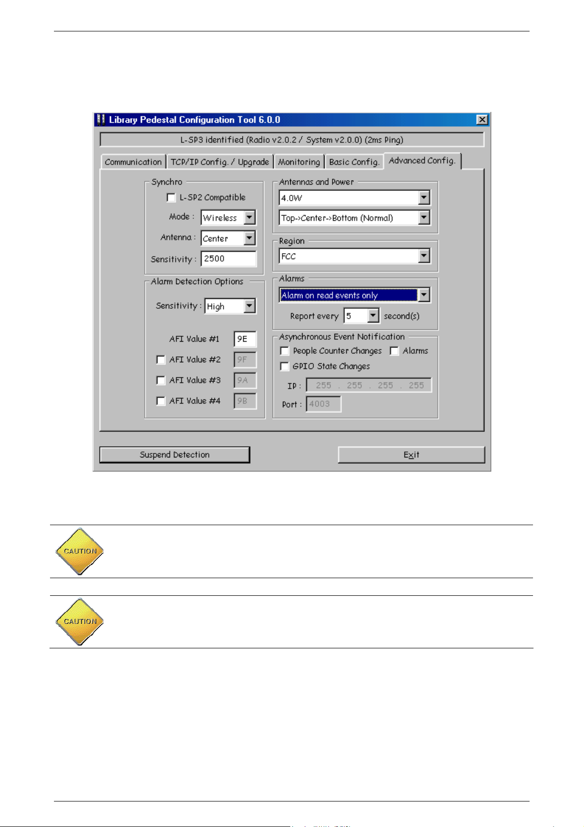
Figure 1: FCC maximum Power and Region settings (Uplink Data Rate)
CAUTION: In any case, for operational configuration this value should not exceed 4W to be in
compliance with FCC. The “Antennas and Power” parameter in “Advanced Configuration” Tab
does not allow setting a higher power value than 4.0W at most. Please see above Figure 1:
FCC maximum Power and Region
CAUTION: ISO15693 uplink data rate you should not exceed 1.65kbits/s in order to comply
with FCC standard certification. To do so, set the “Region” parameter in “Advance
Configuration” Tab to “FCC”. See above Figure 1: FCC maximum Power and Region
settings
.
settings
.
December 2009 Revision 2.1 15/68
Page 16

3 System Overview
3.1 Features
Being a standalone solution, TAGSYS security pedestal do not need to be linked to the
library database, and can still operate when the Integrated Library System (ILS) is down or under
maintenance. The security pedestal does not require additional equipment to operate.
The L-SP3 pedestal features:
Multi-protocol features which makes it compatible with ISO15693 chips
NXP proprietary EAS mode supported for the C370 (NXP SLI), C370-L (NXP SLI-L)
chips
AFI mode supported, with configurable AFI value (Multiple AFI values, up to 4)
TAGSYS proprietary C220/C320 EAS burst detection support
TAGSYS proprietary C320 256 bits memory reading in NSNT single tag mode.
Multiple items Read-Memory supported in EAS mode for C370 (NXP SLI), C370-L
(NXP SLI-L)
Standard Multiple items Read-Memory supported in AFI mode using the optional
command Read Multiple Blocks as described by the ISO15693-3
Enhanced Multiple items Read-Memory supported in AFI mode for C370 (NXP SLI),
C370-L (NXP SLI-L), Tag-it ™HFI (Texas Instruments) chips, LRI-2K (STM).
Read-Memory Data Model: up to 896-bits (28 blocks of 32bits)
One electronic system block embedded into bottom of Pedestal
A remotely accessible people counter based on dual photoelectric sensors coupled to a
reflector, allowing in and out traffic monitoring.
Ethernet Networking Link communication for set up, database and patron counter value
retrieval
Asynchronous Event Notification over the Network: pedestal sends automatically data
upon Book Detection, Patron Counter change, GPIO level change or Pedestal fault
detection.
Trigger input to quickly power up and down remotely the pedestals using light cells
before and after the pedestal area. This lowers down the radio emission levels to the
strict minimum necessary.
One Extra Open Drain Output to drive External Alarm Device: Webcam, Extra Remote
Display or Sound
This is a cost effective security system as it only requires a single RFID tag for both anti-theft and
identification purposes.
16/68 Revision 2.1 December 2009
Page 17
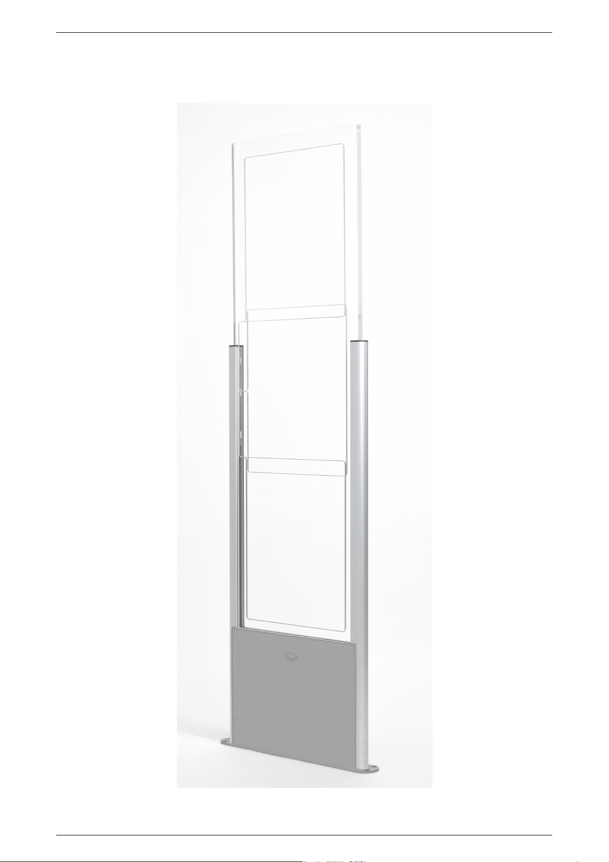
3.2 Brief L-SP3 Description
Figure 2: LSP3 Clear Panel Overview
December 2009 Revision 2.1 17/68
Page 18

The components of the L-SP3 EAS system are contained within the L-SP3 pedestal. At
least two pedestals are required for each EAS gate. A set of pedestals is known as a gate and may
consist of several pedestals. Please see section 4 “Installation” for more information.
The L-SP3 is built in a one frame:
An L-SP3 Electronics unit is used to control each pedestal. This electronics unit
generates the RF signal transmitted by the antennas and picks up the reply from the
RFID tag. If an activated RFID tag is detected, the electronics unit will activate the
LED/buzzer alarm
These antennas are sensitive receivers used to detect the theft bit status and the AFI
value of the RFID tag as it passes through the EAS gate
Visual and audible warning devices
A remotely accessible people counter equipped with dual light barrier photoelectric
sensors.
To operate, the L-SP3 will only need an IEC power supply cable, avoiding unnecessary mains
cable wiring up.
An IEC Mains Supply Cord Outlet is available to allow daisy chaining. A series of up to 5 pedestals
can be powered up from a single wall socket.
18/68 Revision 2.1 December 2009
Page 19
4 Installation
4.1 Recommendations before Installation
4.1.1 Wire Feed Sheaths
Within the framework installation you need at least a power supply cable sheath and an
Ethernet cable sheath to connect to the Ethernet network. These sheathed cables will be located at
the bottom center of the pedestal as shown in Figure 10.
If needed according to the installation configuration, extra sheathed cables need to placed
for wire synchronization, Trigger cable and to remotely switch the RF on & off and I/O cables to
drive external devices (Camera, Remote alarms…).
The L-SP3 is delivered without any IEC terminated plug power supply cable or Telecommunication
cable. It is up to the Local installation personnel to use the appropriate IEC Power Cord according
to local electrical regulations.
Use appropriate IEC power cord according to the local regulations to
power up and interconnect the pedestals.
The Power Supply Cord is the LSP3 Product Main Disconnecting Device,
It should be easily accessible at any time to Disconnect the pedestals
from the mains power supply.
December 2009 Revision 2.1 19/68
Page 20
4.1.2 Electrical Safety Rules
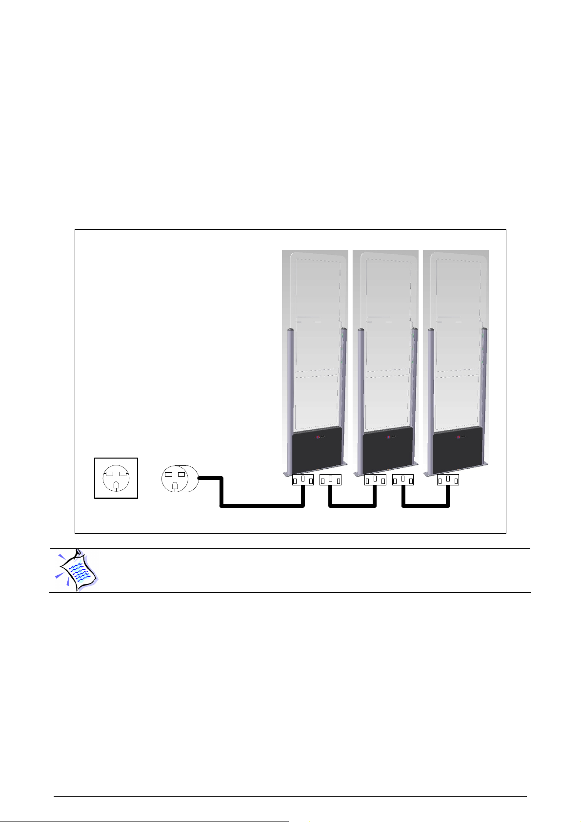
The L-SP3 is powered up via a Mains Supply IEC Cord.
A group of up to 5 Pedestals can be daisy chained and powered via a single IEC power
cord connected to a wall socket. The mains wall socket should provide at least 2 Ampere and be
protected by a differential circuit breaker limiting the current to 5 Ampere maximum.
Figure 3 here below shows how to connect the L-SP3 pedestals to the mains.
Figure 3: Safety Electrical Installation Using Power Cord
LSP3 Pedestals Aisle
Wall
Socket
IEC Power Cord
The electrical installation must be carried on by qualified personnel only.
For each country where installation takes place, an adequate IEC power
supply Cord must be used, fitting the local wall socket layout.
4.1.3 Network cable installation
The L-SP3 Pedestal delivery package does not include an Ethernet cable to connect to a Local
Area Network for remote operation. We recommend the use of a Shielded Ethernet cable, UTPCat 5.
20/68 Revision 2.1 December 2009
Page 21
4.2 L-SP3 RFID System Components
The components included in the L-SP3 RFID System package are listed in Table 1
Table 1: L-SP3 System Components
Quantity Description
1
8
1
L-SP3 Pedestal
40 mm Philips-head, countersunk screws with a diameter of 6 mm
2 ways 3.81mm Green Screw Tightening Plugs Vertical Cable Entry for
Synchronization Cable
1
4 ways 3.81mm Green Push-On Plugs Vertical Cable Entry for I/O Wiring
4.3 L-SP3 Pedestal
CAUTION: This equipment is intended for indoor use only under the
conditions described in this document. Should it be used outside these
conditions cannot be guaranteed, and is not recommended. Please read
section 1 “Publishing Information” before installation or use.
4.3.1 Tools Required
The following tools are required during installation:
Measuring Tape
Square
Hand Drilling Machine with 4 mm, 8-mm and 19-mm drilling bits
Philips-head screwdriver
Spirit Level
4.3.2 Placement of Pedestals
Pedestals must be mounted between 800mm and 980 mm apart (edge to edge) for
maximum reliable performance. There should be at least one pair of pedestals at each
entrance/exit point of the library. There should be a pedestal at each edge of the entrance, and a
clear space of at least 500 mm around the edge of the pedestals to ensure that the antennas will
not be detuned. This clear space must not contain any metallic objects, but may contain some
substrates such as non-metallic/non-conductive building materials such as wood, glass,
chipboards and plasterboards.
CAUTION: In case several Pedestal rows (group of Pedestals) to be
installed it is mandatory every L-SP3 being positioned in the same
direction (all people counter of each looking toward the same direction).
This would prepare the installation for future implementation of direction
sensing.
Be cautious to properly align the pedestal in order to centre the photoelectric beam sensor on the
reflector of the next pedestal.
December 2009 Revision 2.1 21/68
Page 22

CAUTION: Each L-SP3 should be installed within following tolerances:
C
A
B
Horizontal angular alignment tolerance with reference to pedestals
alignment: 0° +/-2°
Vertical angular tolerance with reference to ground surface : 90° +/-1°
CAUTION: Each L-SP3 must be installed at least 2 meters away from
sliding doors. Metal frames do pick up & radiate stray Radio ham
electromagnetic field which can lead to false triggering. Prior to
installation a site survey is highly recommended.
Figure 4: Clearance Distances around Pedestals
A: Indicates the distance (6 ft.
6in.) to a permanent librarian
position.
B: Indicates the distance (8 ft.)
from other RFID stations.
F 30 ft. (9.1 m)
C: Indicates the recommended
distance (36 in. face panel to
face panel) between
pedestals.
D: Indicates the minimum
distance (31½ in.) between a
pedestal and large metal
object.
6 ft. 6 in. (2 m)
31½ in. (80 cm)
36 in.
E: Indicates the minimum
distance (20 in.) between a
pedestal and small metal
object.
F: Indicates the minimum
distance (30 ft.) between
Master pedestals (specific
synchronization ID, see
section 5.2 “Understanding
the L-SP3 Synchronization
Process”).
8 ft. (2.4 m)
(91.4 cm)
20 in. (50 cm)
4.3.3 Installing the Pedestal
Once the L-SP3 will be powered, the photoelectric sensors will emit a red light beam. To
precisely align the sensors and the reflector, an orange LED is present on the back of the
photoelectric sensor. When the orange LED is continuously on, the sensor and the reflector are
perfectly aligned.
To see these LED, one must first unscrew the Plastic Bottom Cover covering the dual cells
(see picture of 5.5.1 Resetting the Counter Display).
On the contrary when the orange LED is blinking or off, then you have to adjust the photoelectric
sensor, so that the red light beam is centered with the opposite reflector. This operation is
achieved using a white paper to clearly see where the red light beam is pointed at. When perfectly
centered, the orange LED will continuously be ON.
On figure 7 below, the two Beam Crossing Cells support is shown. To do a fine adjustment of 2
beams, use a hexagonal key to screw or unscrew the top left screw (to adjust height of beams) and
the bottom right screw (to adjust the lateral positioning of the beams). They are spring loaded to
improve accuracy and keep in place the two sensors after adjustment.
22/68 Revision 2.1 December 2009
Page 23

Special attention must be taken for the 2 pedestals positioning:
They must be positioned facing each others
They must be parallel
They must be well aligned and well centered.
The orange LED must be continuously ON when powered (See Figure 5)
If the orange LED still blinks when perfectly aligned and centered, check that the spacing
does not exceeds the recommended values.
For correct In & Out counter operation, the pedestals must be placed according to the
library flow of patrons. See Figure 6 and Figure 7 for In & Out counting direction.
Figure 5: Light Barrier Orange and Green LED Lit when positioning Correct
Before final Installation, do make sure that the Entrance flow is in line
with the in Counter Increment Direction Described in Figures Figure 6
and Figure 7.
There is no mean to change the In & Out Counter Direction by software
afterward.
Then the 2 pedestals can be secured to the ground.
A good positioning will ensure the two red LED beams to be back scattered by the reflector as
shown below. See Figure 5 for LED positioning.
December 2009 Revision 2.1 23/68
Page 24

Way in Counter
Left Hand Light Beam
Right Hand Light
LCD Counter Display
Buzzer Level Adjust
Right Hand
Reflector
Parallel
Reflector
Left Hand
In Counter
Out Counter
1
2
3 4
5
6
7
8
Figure 6: Top view of correct L-SP3 installation and In/Out Counter Directions
Light Beam
Light Beam
Incremented
Incremented
Figure 7: People Counter View when facing light barrier and counter display
Figure 8: Light Beam Crossing Detection Cells & Display
24/68 Revision 2.1 December 2009
Page 25

Ground
Reflector
Table 2: Description of Buzzer & Counter board Components
Reference n° Designation
1 Buzzer Volume Adjustment
2 Buzzer
3 Photoelectric Reflex Switch Red Beam
4 Photoelectric Reflex Switch Red Beam
5 LCD Display & Counter
6 Counter Reset Push Button
7 Hexagonal Screw for Light Beam Vertical Alignment
8 Hexagonal Screw for Light Beam Horizontal Alignment
On Figure 8 above, the two Beam Crossing Cells support is shown. To do a fine adjustment of the
2 beams, use a hexagonal key to screw or unscrew the top left screw (to adjust height of beams ref
7 circled) and the bottom right screw (to adjust the lateral positioning of the beams ref 8 circled).
They are spring loaded to improve accuracy and keep in place the two sensors after adjustment.
Figure 9: Side view of correct L-SP3 installation
December 2009 Revision 2.1 25/68
Page 26

After having defined the location of the pedestals, refer to the mechanical drawing of the pedestalmounting diagram (Figure 10). The pedestal is fastened to the floor using screws that are strong
enough to support the weight of an average adult falling against the pedestal.
Figure 10: Pedestal Mountings
1. Identify and mark the location of the holes to be drilled for mounting the pedestal to the ground.
The use of a tape measure and a square is recommended.
2. Drill the cable access and mounting holes according to the type of ground surface:
a. Wooden floor: Drill eight holes with a diameter of 4 mm for the mounting screws and
one hole with a diameter of 19 mm for the cable access.
b. Cement floor: Drill eight holes with a diameter of 8 mm for the cement floor plugs and
one hole with a diameter of 19 mm for the cable access. It may be necessary to provide
a groove for the power supply cable connected to the L-SP3 Electronics Unit. Insert the
concrete floor plugs into the mounting holes.
CAUTION: Always use a protective sleeve for main power cable, which
match to the flammability grade of the product. Mains power cable must
be a 3 wire (line, neutral and earth), multi stranded copper wire,
minimum section of 0.75 mm²/ 3A)
Figure 11: L-SP3 Clear Bottom Plastic Cover (4 screws)
26/68 Revision 2.1 December 2009
Page 27

3. Remove the pedestal from the box.
4. Remove the plastic cover from the both sides after removing the 4 fixing screws.
5. Engage the power supply cable in the electric sheath and the Ethernet cable in the other
sheath (please refer to section 4.1.1 “Wire Feed Sheaths”).
6. Place the pedestal base over the mounting holes. Insert and fasten the screws in the mounting
holes according to the type of ground surface:
Wooden floor: Insert the screws directly into the mounting holes and tighten the screws in
place.
Concrete floor: Insert the screws into the concrete floor plugs and tighten the screws in
place.
When tightening the screws in place, first tighten the screws in place ¾
of the way. Once all screws are in place, then tighten each screw
progressively, one after each other to ensure that the floor bracket is
solidly fixed into place and completely vertically aligned. The use of a
level may be required.
7. Plug in the mains IEC power cord from the previous pedestal if daisy chained or from the wall
mounted socket. See figure in Chapter Electrical Safety Rules
No Live AC mains 110/230V during installation!
Make sure there is no power supply current before carrying on the
connection operations.
To do so, unplug the IEC Power Cord from the wall socket.
8. Once all the L-SP3 pedestal have been installed, close the micro circuit-breaker (Figure 3) to
power up the system before starting configuration operations. Please see section 5
“Configuration”.
9. After the configuration has been carried on, replace the two plastic covers and tighten the 4
fixing screws.
December 2009 Revision 2.1 27/68
Page 28

5 Configuration
All configuration operations of L-SP3 systems are carried on with the L-SP3 Configuration Utility
Software.
5.1 Chip Configuration
For optimal performance the scanning duration (T_scan) should not exceed 250ms. T_scan
is the period to scan all pedestals of a group of N pedestals, i.e. a Master and (N-1) Slave
Pedestals. Depending on your chip configuration and the number of pedestals installed you can
determine the scanning duration of your installation.
5.1.1 Scanning duration per pedestal
Table 3: Scanning Duration No Tag in field
Synchronization process
C370/-L, Tag-It, ISO15693 EAS or one AFI,
detection only
C220/C320 EAS detection only
The scanning duration per pedestal will vary according to the configuration you selected. The
scanning duration will always include the synchronization process of 10ms.
Example 1: with a system using the 370-AFI in ETSI mode.
The scanning duration per pedestal will be: T_single _scan = (10ms+20ms) = 30ms
Example 2: with a system using the 370-AFI1-AFI2 in ETSI mode.
The scanning duration per pedestal will be: T_single _scan = (10ms+20ms+20ms) = 50ms
Example 3: with a system using the 370-EAS + C320-EAS in ETSI mode.
The scanning duration per pedestal will be: T_single _scan = (10ms+20ms+15ms) = 45ms
Duration per pedestal
in ETSI mode (ms)
10 10
20 100
15 15
Duration per pedestal
in FCC mode (ms)
5.1.2 Global scanning duration
The global scanning duration (T_scan) will depend on the synchronization mode you have
selected. Hardwired synchronization is faster than wireless synchronization.
Table 4: Global scanning duration versus Synchronisation mode
Synchronization Mode T_scan
Hardwired = T_single_scan x Nb_Pedestals
Wireless
Example 4: with a 4 pedestals system using 370-AFI1-AFI2 in ETSI mode.
The global scanning duration will be: T_scan = 50ms x 4 = 200ms if used hardwired.
The global scanning duration will be: T_scan = 50ms x ((2 x 4) – 2) = 300ms if used wireless.
28/68 Revision 2.1 December 2009
= T_single_scan x
((2 x Nb_Pedestals) – 2)
Page 29

Pt
Synchronization Burst
T_scan
5.1.3 EAS Mode versus AFI Mode
EAS mode is only supported by the C370 or C370-L (NXP chip). AFI mode is supported by most
ISO15693 chips, from major chip manufacturers (NXP, Texas Instrument, STM, Infineon,
MeMarin…).
EAS digital burst is a prime number data stream of 128 bits which is read out after sending a check
EAS command to the Tag. This dedicated EAS command in only implemented in NXP SLI chips.
C220 & C320 TAGSYS chips EAS signal is respectively 100kHz free running and 106kHz
synchronous burst sent by the chip at power on reset during a few ms when RF field is first
established and when EAS bit is set. This mode is only supported by TAGSYS which owns the
chip design. C220 supports only EAS detection, no memory content read out is possible. C320
supports both EAS detection and 256 bits memory content read out for data model support.
The AFI (Application Family Identifier) is an 8bit-field defined in the ISO15693 standard but not
mandatory. Whenever issuing an inventory command with a specific AFI code, only Labels with the
same matching AFI code will reply with its UID. Generally the code 9E is used to say that the book
has not been properly checked out, thus will be detected by the pedestals.
5.2 Understanding the L-SP3 Synchronization Process
5.2.1 Standard Synchronization Mode
To manage a group of pedestals, a synchronization burst is sent by the master pedestal to all
the slaves’ pedestals, a token being propagated back and forth as in a token ring process. This is
called the synchronization process.
Only one pedestal is defined to be the master who emits a synchronization burst to the next
slave in close proximity who in turns emits it to the next slave and so forth.
The other pedestals, configured as slaves, get the synchronization from the neighboring
pedestal and emits back to the next Slave of higher index.
Default Configuration of the L-SP3 is set to Master 2 Pedestals.
Figure 12: Chronogram Sample (1 Master/ 4 Slaves)
MASTER
SLAVE1
SLAVE2
SLAVE 3
SLAVE 4
December 2009 Revision 2.1 29/68
Page 30

Synchronization burst: start burst to synchronize the gates (Period of T Scan ms)
Processing time (Pt): depends on the number of tags to be detected and the settings. The
fastest is when only detection is used (EAS burst or AFI), the slowest when all features are
used (AFI + Read AFI + Read 16 blocks of memory). Refer to the figures in Table 3:
Scanning Duration.
Synchronization process for 3 pedestals:
1- The master scans the configured chip, then sends the synchronization burst to Slave1
2- Slave1 scans the configured chip, then sends the synchronization burst to Slave2
3- Slave2 scans the configured chip, and then sends the synchronization burst back to either
the master when in hardwire mode or to the Slave1 in wireless mode.
This process is repeated indefinitely.
In case the master does not receive back the synchronization burst from the last slave after a
defined period, it will automatically restart the synchronization process.
The number of pedestals is not limited to any particular number as long as each gate is close
enough to its neighboring pedestal and that the overall scanning time does not exceed a few
100ms to allow for a safe detection at 1m/s pace trough any gate.
30/68 Revision 2.1 December 2009
Page 31

5.2.2 Wireless Synchronization
In Standard Synchronization mode, section 5.2.1, if pedestals spacing
exceeds the recommendation of section 4.3.2 “Placement of Pedestals”,
wire synchronization becomes mandatory.
When more than two pedestals are installed, it is mandatory to install the Master on the far left or
right of the slave’s line for a better propagation and detection of the air synchronization burst.
Figure 13 below shows an example of optimal configuration. Slaves must be placed with the
correct index corresponding to its physical location in order to carry other the token allowing
starting to scan its 3 own antennas before handing over the token to the next neighboring pedestal.
Figure 13: 3 Pedestals Configuration Example and Token Propagation
Red Arrow: Wireless Synchronization Token hand over
Blue arrows: Wire Synchronization Token hand over
5.2.3 Synchronization by a pair of Wires
This mode is mandatory in noisy environments or when nearby RFID devices are placed too
near within a couple of meters from any pedestals preventing the installation using wireless
settings.
It is also mandatory when using too many pedestals (typically above 4 to 6 pedestals) as
wireless burst signal needs to go to the last slave N pedestal and then back going through all N
slaves before the master can scan its detection volume again. Processing time is thus equal to 2N
times Pt in wireless mode.
Using a synchronization cable, the token can be directly handed over by the last slave N to
the Master without having to go through all N Slaves pedestals again. Overall scanning time is thus
equal to N times Pt, half of the wireless time.
In this case the L-SP3 configuration settings have to be changed from “Wireless” to
“Hardwire” Synchronization in the L-SP3 Configuration Tool program, “Advanced Configuration”
last tab. See Figure 12 to see the correct fields to be modified. There will always be one & only one
December 2009 Revision 2.1 31/68
Page 32

L-SP3 Master and all others pedestals set as Slaves. Each pedestal is connected to the other
using ideally a twisted pair cable. This cable will propagate the synchronization signal to all
pedestals in parallel.
Wire connection:
First prepare a cable of appropriate length to connect 2 consecutive Electronics as shown in
Figure 14 and Figure 15. A minimum wire gauge of 22AWG (0.2mm²) is enough, preferably a
twisted pair. Screw at each extremity of the cable a 2-way connector with ground wire at the same
position for each module. If more than 2 pedestals are used to form the aisle, then connect the
wires in parallel to go to the next pedestal until you reach the last one.
Figure 14: Detailed of Wire Synchronization Assembly
Then unscrew the 4 screws to open the bottom plastic cover panel of each pedestal forming
the aisle to gain access to the Product Electronic Module and connect the top 2-way connector as
shown in Figure 15 thereafter.
32/68 Revision 2.1 December 2009
Page 33

Buzzer & Alarm Display Connector
24 Volts Power Supply Cable
Unshielded 2
-
wire Synchronization
Cable connecting all Pedestals
GPIO#1 & GPIO#2
Figure 15: PEM Connectors & Cables Location
Shielded CAT5 Ethernet Cable
December 2009 Revision 2.1 33/68
Page 34

Figure 16: Advanced Settings Tab Sections and Fields
Steps to undergo:
1. Prepare a 2 wire cable of appropriate length and number of connectors to wire up each
pedestal. Use the 3.81 mm Push-On Green Plugs Vertical Cable Entry provided.
2. Connect all pedestals Synchronization to the Synchronization I/O as shown on Figure 11.
3. Set each pedestal to hardwire synchronization modifying the “Mode” in the “Synch” Section
of the “Advanced Configuration” tab of the L-SP3 Pedestal Configuration Tool.
4. Write down the MAC address of each pedestal. Use the test button in “Monitoring” tab to
locate it: the connected pedestal will ring and its display lit.
5. Power up the whole system (every pedestal must be powered up) and check that the
synchronization process works properly detecting a book in each passageway.
6. Put the cover panel back into place and secure it with the 4 screws
34/68 Revision 2.1 December 2009
Page 35

5.3 Parameters Configuration of the Ethernet Interface
Don’t forget to power up your installation before carrying on the
following steps
The first step is to allocate a unique IP address to each L-SP3. This operation will allow
identifying each L-SP3 on site before configuring them on the Ethernet network.
By default the IP address is 169.254.0.100 (port 4001) (IPv4 Automatic
Private IP Addressing). Ask your network administrator to obtain a static
IP address for each of the pedestals connected to your local network.
The L-SP3 configuration will be carried on using a host computer connected to the local Ethernet
network.
You can localize the each gate thanks to their IP address. Their on site
location must be known to configure and set them as Slaves or Master.
5.4 Configuration of the L-SP3
“Library Pedestal Configuration Tool” is the software tool used to monitor and configure the
L-SP3 pedestal.
Before you configure the whole L-SP3, you need to have a clear vision of
which pedestals will be masters or slaves. (Refer to section 5.2
“Understanding the L-SP3 Synchronization Process”)
In a configuration with several pedestals, as all pedestals are set as
master by default, they will mutually perturb when powered on. So the
first step will be to set the appropriate pedestals as slaves.
The whole L-SP3 configuration is carried on from a host computer connected to the local
area network. Each L-SP3 is addressed thanks to its own IP.
5.4.1 Installing the Configuration Software
The Library Pedestal Configuration Tool is on the CD-Rom provided with the L-SP3.
Launching the Installer from the CD-ROM will display the following window:
December 2009 Revision 2.1 35/68
Page 36

Follow the installer steps:
36/68 Revision 2.1 December 2009
Page 37

After the Library Pedestal Configuration Tool is installed, a shortcut to the application will be added
to the desktop and to the Start Menu.
Double-click on the application shortcut to start the application.
December 2009 Revision 2.1 37/68
Page 38

5.4.2 Communication Configuration
Figure 17: Communication Configuration Tab (connected to a L-SP3)
This tab is used either:
• To establish connection to a pedestal when its IP address is known.
• To discover pedestals connected to the same network as the PC running the configuration
tool.
• To modify the TCP/IP configuration of a discovered pedestal (not including port) if this
address is not coherent with the address of the network it is connected to.
Connecting to a pedestal when its IP address is known
Select “Ethernet/Wifi” as the Com Mode, enters the pedestal IP address and Port in the
appropriate fields and click “Init Communication”. Status bar on top of the window area should now
display pedestal model and firmware revisions.
Click “Release Communication” to disconnect from a pedestal.
38/68 Revision 2.1 December 2009
Page 39

Discovering pedestals connected to the network
Click “Discover Devices” when not connected to a pedestal. After a few seconds, the list of
discovered pedestals (IP Address, Port and MAC address) is displayed. Double-Click an item in
the list to connect to the corresponding pedestal.
In case a pedestal is properly discovered but connection attempts fail, please make sure that :
• No other host is already connected to the pedestal.
• The IP address that appears in the list is correct and coherent with the address of the
network the pedestal is connected to. If the IP address is incorrect, please follow the
procedure below.
Modifying TCP/IP configuration of discovered pedestal (not including port)
First discover pedestals as described above. Then right-click the list item corresponding to the
pedestal whose IP address must be modified. Select “Configure TCP/IP” in the pop-up menu. The
following window appears:
Figure 18: TCP/IP Configuration Window
Fill the fields with the appropriate data then click “Apply and Reboot” to apply new configuration
and reboot pedestal. After a few seconds, you should be able to connect to the pedestal.
Click “Cancel” to cancel the operation.
This procedure is applicable even if connection to the pedestal is
impossible because another host is already connected to it, or because
its IP address is incoherent.
Another procedure is available to modify TCP/IP configuration of a
pedestal including port and without having to reboot it immediately (in
this case, changes will be applied upon next reboot). However, this
procedure requires that a connection is established to the pedestal (see
section below).
December 2009 Revision 2.1 39/68
Page 40

It is possible to revert to the default settings (DHCP active, fallback IP
address set to 169.154.0.100). To do so, power-off pedestal, press and
hold the LCD button, power-on pedestal, wait 5s then release LCD
button.
5.4.3 TCP/IP Configuration and Firmware Upgrade
Figure 19: TCP/IP Configuration and Firmware Upgrade Tab
This tab is used either:
• To upgrade System Firmware.
• To upgrade Radio Firmware.
• To modify TCP/IP Configuration, including port.
Upgrading System Firmware
Click “System Upgrade”, and then select the appropriate firmware file. A bar shows the progress of
the upgrade process. After upgrade is completed, you can decide to run the new firmware
immediately by rebooting the pedestal, or to wait for next reboot to run it.
Upgrading Radio Firmware
Click “Radio Upgrade”, and then select the appropriate firmware file. A bar shows the progress of
the upgrade process. After upgrade is completed, you can decide to run the new firmware
immediately by rebooting the pedestal, or to wait for next reboot to run it.
40/68 Revision 2.1 December 2009
Page 41

When upgrading both System and Radio firmware, it is advised to reboot
the pedestal only once after both upgrades are completed.
The EAS detection is suspended during the upgrade process.
Do not power-off pedestal during the upgrade process. Failure to respect
this procedure may corrupt pedestal firmware and require product to be
sent back to TAGSYS.
In case of a software failure during the upgrade process, do not poweroff the pedestal, restart the configuration software and try upgrading the
pedestal again.
Modifying TCP/IP configuration (including port)
Fill the fields with the appropriate values and click “Apply Changes”. You can then decide to apply
the new TCP/IP configuration immediately by rebooting the pedestal, or to wait for next reboot to
apply it.
5.4.4 Monitoring Pedestal Activity
Figure 20: Pedestal Monitoring Tab
December 2009 Revision 2.1 41/68
Page 42

This tab is used either:
• To check / update pedestal clock.
• To check / toggle GPIOs Level.
• To check antenna noise level.
• To check / configure people counter.
• To check alarms database.
Checking / Updating pedestal clock
Pedestal clock is displayed in real-time in the “Date & Time” section. Click “Synchronize Time” to
synchronize pedestal clock with computer clock.
Pedestal clock is used as a date stamp when a theft is committed.
Checking GPIO level
The two GPIO available to user can be monitored:
Display shows “High” when voltage level is above 2 Volt.
Display shows “Low” when voltage level is below 1 Volt.
See Table 3 for more detailed information.
Clicking with the mouse on GPIO text field, the Level value toggles between High & Low.
The effect will depend on the actual GPIO settings on Basic Configuration Tab.
GPIO #1 can be set as an Input Trigger for RF powering off/on as well as
an Output for driving an External Alarm Device
GPIO #2 can only be used as an Output for driving an External Alarm
Device
Checking antenna noise level
In “Antenna Noise Level” section, bar graphs provide a feedback regarding the ambient noise level
measured by each antenna. It is only provided as debug purpose and should not be seen as a
measure of performance. Green shows standard conditions as opposed to orange and red displays
warning of possible/likely performance reduction due to ambient noise level.
Checking / configuring people counter
The “People Counter” section displays the total number of people that crossed the IR sensor:
• Whatever the direction (In & Out) if no bidirectional IR sensor is installed.
• In each direction (In & Out) if bidirectional IR sensor is installed.
People counter value is battery backed-up, and is consequently restored
at power-up.
An icon briefly appears in real-time in “People Counter” section as the sensor IR beam is crossed.
42/68 Revision 2.1 December 2009
Page 43

Click on “Clear People Counter” button to reset people counter.
To reset people counter, you can also use a pointed element (for
example, a paper clip), insert it in the hole on the left of the display
window and press (not too strong) until zero is displayed.
Use the drop-list in the “People Counter” section to select which count is to be displayed on
pedestal LCD:
• “Display In + Out Counter” to display the sum of In and Out counters.
• “Display in Counter” to display In counter only.
• “Display out Counter” to display out counter only.
Pedestal must be rebooted for changes to take effect.
The drop-list is not available if no bidirectional IR sensor is installed. In
this case, pedestal LCD always displays the sum of In and Out counters.
Checking alarms database
Each time an item (with EAS/AFI activated) passes through the gates an entry is added to a local
database in pedestal memory. This entry holds the following information:
• The date and time to which the theft was committed.
• The chip type.
• If selected, the memory contents.
• If selected, the UID.
• The method used to detect the alarm (EAS or AFI).
A red icon appears in real-time in “Database” section as thefts are committed.
The “Database” section also shows the number of entries stored in pedestal memory in real-time.
To display database contents, click “Access Database”. Database is downloaded and the following
window is displayed:
December 2009 Revision 2.1 43/68
Page 44

Figure 21: Database Window
When this window is open and “suspend detection” check box is
selected then EAS/AFI detection is automatically suspended. It is
resumed when the window is closed.
If “suspend detection” check box is not selected then detection is not
suspended (in this case database download may be slower).
In “Database” window:
• Click “Refresh” to update database display.
• Click “Clear” to permanently erase pedestal database.
• Click “Close” to close the window.
You can access pedestal database from your own applications using the
provided SDKs (Win32/x86 native DLL, WinCE/Arm native DLL and JAVA
archive).
44/68 Revision 2.1 December 2009
Page 45

5.4.5 Basic Pedestal Configuration
Figure 22: Basic Pedestal Configuration Tab
This tab is used either:
• To select the chip to be detected as well as detection options.
• To configure inter-pedestal RF synchronization.
• To configure / test alarm duration.
• To configure the 2 GPIO available to user with predefined functions.
Selecting the chips to be detected as well as detection options
In the “Chips” section, first tick the family of chips to be detected:
• TAGSYS proprietary C220 asynchronous or C320 synchronous legacy chips
• ISO15693 synchronous chips: NXP, TI or Generic (no support of multiple memory Blocks
Reading in Inventory mode). Select the ISO15693 chip type from the drop-list.
• Or both C220/C320 and then ISO15693 EAS detection.
December 2009 Revision 2.1 45/68
Page 46

In the “Chips Options” section:
• Select the detection method to be used in the drop-list, i.e. “Use AFI”, “Use EAS”, or “Use
both EAS and AFI”.
• Select “Read UID” to have the pedestal trying to read the UID of stolen items.
Select “Read Memory” to have the pedestal trying to read the memory contents of stolen items. If
“Read Memory” is selected, you must specify the first block and number of blocks to be read in the
corresponding fields. You must also specify which blocks should be reported first (lowest or
highest) by selecting/unselecting the “Lowest Blocks First”
Configuring / Testing alarm duration
In the “Alarm Duration” section:
• Select the alarm duration in the drop-list.
• Click “Test” to trigger an alarm (this is useful either to test alarm duration, or to identify the
pedestal you’re connected to).
Configuring inter-pedestal RF synchronization
In the “Synchro” section:
• Select whether the pedestal is to be configured as the Master or as a Slave (1…8).
• Select the total number of pedestals (master and slaves) operating in close proximity and
sharing the same ID.
• Select ID (master and slaves of one system installation must share the same ID)
Only one Master can be selected with several slaves.
For example, in the library configuration shown below we have:
• System A with ID = 1 (M1 Master, S1, S2, S3 Slaves).
• System B with ID = 2 (M2 Master, S1, S2 Slaves).
The Masters are disposed as far as possible from each other not to perturb themselves (Please
refer to section 4.3.2 “Placement of Pedestals").
Two different IDs are used to be sure that each slave will be synchronized with the master from its
own system.
46/68 Revision 2.1 December 2009
Page 47

System A
ID = 1
System B
ID = 2
Nearby area with
M1 S1 S2 S3
M2
Figure 23: Multi-gate configuration with two different IDs
interferences
S1
S2
Once you have set the basic configuration, check that all the slaves are
well synchronized. To do so, L-SP3 electronics unit green LEDs should
flicker cyclically. If not, proceed to the advanced configuration stage.
Configuring General Purpose Input/Output
When needed, port #1 can be used as an input to remotely switch the RF Field on and off. This is
useful to limit the HF field generation to a strict minimum, i.e. whenever a person is about to enter
the detection passageway crossing a light barrier placed ahead of the pedestal and keep it on for a
fixed duration or whenever the person is exiting the RFID detection area using a second light
barrier beam crossing detector.
Refer to Figure 25 for the pin layout to wire the Input and output signals.
In section GPIO#1, select one of the available options:
• GPIO: Port has no predefined function; it can be driven remotely by Host PC via API.
• Input Trigger: when wired signal matches the Active Level Setting (“Low” or “High”) the
Radio Frequency Field will be turned On, Theft detection becoming active.
• Output Trigger: when Theft is detected (EAS or AFI signal setting the alarm), the Port
Signal level matches the Active Level Setting (“Low” or “High”). The output voltage level of
the port should match the active voltage to set the external alarm device wired up.
In section GPIO#2, select one of the available options:
December 2009 Revision 2.1 47/68
Page 48

• GPIO: Port has no predefined function; it can be driven remotely by Host PC via API.
• Output Trigger: when Theft is detected (EAS or AFI signal setting the alarm), the Port
Signal level matches the Active Level Setting (“Low” or “High”). The output voltage level of
the port should match the active voltage to set the external alarm device wired up.
Whenever the GPIO is set as an Output Trigger, It is possible to set a pulse Width and a Pause in
milliseconds. In Figure 24, the Pulse Width is set to 100ms. This means that whenever theft
detection occurs, the signal on port#2 will go from low to high for a minimum time of 100ms. If no
further detection occurs before the 100ms timing laps, then signal will drop to low level.
Whenever after the Pause timing, if a new detection occurs, signal will rise again to high level.
In the particular case of the Pause Timing set to 0ms, whenever detection will occur timing equal to
Pulse setting will be added up so that the active level will stay high as long as detection will occur
(so called retrigger configuration).
Setting pause timing to a value different from zero will force the output signal to low level for Pause
time after the Pulse time set, before being triggered again by a subsequent detection.
Figure 24: GPIO Pulse & Pause Field
Pin # Function
1 Ambient Light +24V
2 Ambient Light 0V Ground
3 Alarm +24V
4 Alarm 0V Ground
5 GPIO #1 Open Collector
6 GPIO #1 0V Ground
7 GPIO #2 Open Collector
8 GPIO #2 0V Ground
Figure 25: Peripherals & GPIO Green Connector Pin Out & Location
48/68 Revision 2.1 December 2009
Page 49

Table 5: GPIO Pins - Electrical Characteristics Max Ratings
Parameters Min. Typ. Max. Unit
Input Voltage Range 0 -- 28 V
Input Voltage (Low Level) 0 -- 0.9 V
Input Voltage (High Level) 1.5 -- 28 V
Output Voltage Range 0 -- 28 V
Maximum Continuous Output
Current
--
--
1.4 A
Output Over Current Protection 1.9 2.8 3.8 A
In output mode the LSP3 GPIO can only sink current to ground. User
needs to provide adequate DC Limited Current Supply to Port#1 and
Port#2 (Open Drain). See Figure 26 for detailed circuitry.
Figure 26: Internal Circuit of GPIO and External Supply Wiring in Output Mode
December 2009 Revision 2.1 49/68
Page 50

Figure 27: Connection of a Switch as an Input Device.
50/68 Revision 2.1 December 2009
Page 51

Figure 28: Connection of a Source and Sink Current Supply as an input Device
Applying negative voltage may destroy the GPIO!
Beware not to inadvertently toggle the GPIO from Input to Output Mode:
you may create a short circuit when using a high current source to
ground as an input device! Refer to Figure 28.
December 2009 Revision 2.1 51/68
Page 52

5.4.6 Advanced Pedestal Configuration
Figure 29: Advanced Pedestal Configuration Tab
This tab is used either:
• To configure advanced inter-pedestal RF synchronization parameters.
• To configure advanced alarm detection parameters.
• To configure advanced alarm signaling parameters.
• To configure antenna sequence, RF output power and region of operation.
• To configure the Asynchronous Event Notification over the network
Configuring advanced inter-pedestal RF synchronization parameters
In “Synchro” section, select whether synchronization should be compatible with L-SP2 pedestals.
Please note that some features may not be available when this mode is selected.
You can also select whether to use hardwire synchronization (see section 5.2.3) or wireless
synchronization (see section 5.2.2).
52/68 Revision 2.1 December 2009
Page 53

S1 M S2
Transmitting
Receiving
If wireless synchronization is selected:
• Select the antenna that should be used for emitting and receiving synchronization bursts.
• Select the synchronization burst detection sensitivity. If default value does not ensure the
correct synchronization of all slaves then it is possible to adjust the sensitivity of the nonsynchronized slaves. You just have to adjust the detection level until you get the required
synchronization (LEDs flickering cyclically). Sensitivity can be adjusted between 50 (high
sensitivity) and 2000 (low sensitivity).
A Value of 2500 & above is recommended for first installation to avoid
synchronization being blinded by nearby operating equipment and
noise.
Figure 30: Master/Slaves Synchronization Antenna Best Configuration
Antenna
Antenna
Best Air Synchronization Results are obtained when using the same
antenna for all Receiving and Transmitting antennas: all Top or all
Centre ones.
Configuring advanced alarm detection parameters
In “Alarm Detection Options” section:
• Select alarm detection sensitivity. Decrease sensitivity in case too many false alarms occur.
Configuring advanced alarm signaling parameters
In “Alarms” section:
December 2009 Revision 2.1 53/68
• Select up to four different AFI values as two hexadecimal digits. Items whose AFI matches
one of those values will trigger an alarm.
• Select the alarm report interval. If the same stolen item passes through the gate several
times, it will be reported only once every n seconds.
• Select whether or not the alarm should be triggered only if reading of UID/Memory of stolen
items was successful.
Page 54

Configuring antenna sequence, RF output power and region of operation
In “Antennas and Power” section:
• Select the RF output power. The output power can be lowered to avoid disturbing nearby
RFID systems (in such a case, check system performance). The output power can be
increased, but only to carry on tests.
• Select antenna sequence used when scanning the pedestal. Select “Top>Center>Bottom”
for standard operation or specifically an antenna for diagnosis operations (Top, Center or
Bottom).
In any case, for operational configuration output power should not
exceed 4W to remain compliant with Radio Regulations.
In “Region” section, select the EMC regulations applicable to your region (FCC or ETSI).
Configuring & Enabling Asynchronous Event Notification Mode
In this section, one can activate the useful Event Notification, a stand alone feature which
duplicates the database entry by sending to any PC on the network a data frame. This allows
sending alarm data whenever an event occurs in any pedestal without having to regularly pool the
pedestal database over the network. It limits the traffic over the network.
To activate the Event Notification, just tick at least one Event out of the 3 available. All Events can
be selected if needed.
If IP address is left to the default “FF.FF.FF.FF.” data is broadcasted to all equipments on the
network. Possible Events are:
• People Counter Change: Whenever one walks through the gate passageway, data is sent
over the network once. The Data field includes the new In Out and In+ Out value.
• Alarms: Upon Tag(s) detection their UID & Memory Contents is sent over the network
according to the settings defined.
• GPIO State Changes: Whenever an Input or Output level changes it is notified over the
network. The data field reports the GPIO new status.
.
Figure 31: Asynchronous Event Notification Subfield.
54/68 Revision 2.1 December 2009
Page 55

Buzzer Level
Counter Reset
Button
LCD Counter
5.5 People Counter & Buzzer Sound Management
5.5.1 Resetting the Counter Display
Adjust
Display
Figure 32: People Counter & Detection Cells Location
To reset the LCD display use a pointed element (for example: a paper clip). Insert it in the hole on
the right of the display window and press (not too hard) until you get zero displayed. This will also
reset the battery backed-up counter.
5.5.2 Resetting the Remote People Counter
See section Checking / Configuring people counter of 5.4.4 Monitoring Pedestal Activity for more
information.
5.5.3 Adjusting the Level of the Buzzer Sound
Using a flat headed 4mm screw driver (less than 4mm max diameter) through the outermost left
hole, adjust the buzzer sound to the desired level turning clockwise or anticlockwise.
To trigger the alarm during the trimming operation, either use a book with an EAS set label or
depress the Test Button on the Basic Configuration Tab of the LSP3 Configuration Tool.
December 2009 Revision 2.1 55/68
Page 56

6 Operation
6.1 Theory of Operation
The RF motherboard in the electronics unit produces radio frequency (RF) electromagnetic
signals that are transmitted via the antennas in each pedestal. Each antenna transmits for a short
period, receives for a short period, and is inactive for the remainder of the time.
6.2 Starting the System
There is no ON/OFF switch. The system operates when mains power is applied plugging in the
IEC plug into the Wall mounted plug.
6.3 Normal Operation
No operating procedures are required. The system continues to operate as long as power is
supplied.
6.4 Shutdown
Once the system is set up and running, we recommend that all pedestals remain turned on at all
times.
56/68 Revision 2.1 December 2009
Page 57

7 Maintenance
7.1 Servicing the Pedestals
No regular servicing or maintenance is required, except for keeping the covers clean, and
occasionally checking the integrity of the cover seals.
It is recommended that the pedestal unit be inspected at least once per year by an approved
TAGSYS technical representative.
Refer to section 1.2 “Care and Maintenance” for general maintenance information.
7.2 Servicing the Electronics Unit
- Fuse characteristics:
F1 on AC mains: Schurter FST, 5X20mm, Time-Lag T, H, 250VAC, 500mA
F2 on DC supply: Schurter SPT, 5X20mm, Time-Lag T, H, 250VAC/300VDC, 2A
- How to change them:
Fuses are located behind the plastic cover located at the bottom of the L-SP3 pedestal.
1. Unscrew the 4 screws holding the plastic cover on sensors and counter display side.
2. Unscrew the fingertip head fuse and replace the tripped fuse with the specified replacement
one. Only use the specified UR listed 5x20mm fuses from Schurter for replacement (please
see figure below).
Figure 33: Mains Fuses Location and Ratings
24V DC Secondary Fuse F2: 2A 300V DC
IEC Mains Voltage Outlet
IEC Mains Voltage Inlet
Mains Fuse F1: 0A5 250V AC
December 2009 Revision 2.1 57/68
Page 58

WARNING: Beware of Hazardous AC mains 110/230V Voltage!
Make sure there is no power supply before carrying on maintenance
operation.
To do so, the micro circuit-breaker must be opened and the Main Power
Supply Cord Unplugged from the Wall Socket.
58/68 Revision 2.1 December 2009
Page 59

8 Troubleshooting
The following table lists the most common problems and describes their solutions.
Table 6: Troubleshooting Table
Fault Possible Causes Solution
No power
Alarms missed (TAGSYS
RFID tags with theft bit ON
not triggering alarms).
False alarms (TAGSYS
RFID tags with theft bit
OFF trigger alarms).
Differential or micro circuit
breakers
Check the differential and
micro circuit breaker
status
System fuse Replace fuse.
Check cabling and
Cabling fault.
Power cable fault
connections.
Replace any suspected
faulty cables.
Tuning fault. Check antenna tuning.
Tuning fault. Check antenna tuning.
Nearby devices are
interfering with the
pedestals. (Refer also to
section 8.1)
Switch off all or some of
the suspicious nearby
devices and check if the
EAS detection
performance changes. (If it
does, check for a power
problem with the pedestal.)
CAUTION: These distances are subject to site variables. Distance may
be smaller under some conditions. Metal frames on furniture and fixture
items may interfere with the EAS system if they are too close. This is
because energy from the antenna can couple into the metallic frame and
be transmitted to TAGSYS RFID tags and antennas several meters away.
8.1 Sources of Interference
The following devices may cause interference with EAS systems if they are close to the pedestals:
TAGSYS RFID tag readers and programming devices
computer monitors or screens (cathode ray tubes)
radio transmitters
short-wave radios
high power music systems with D-class amplifiers
some industrial vacuum cleaners
high-frequency fluorescent lights (if very close to pedestals)
neon or halogen lights such as advertising signs
equipment using switch mode power supplies
December 2009 Revision 2.1 59/68
Page 60

data or power cables within 400 mm
illuminated exit signs generating noise between 80 and 100 kHz
digital phone lines (wideband noise) within 200 mm
60/68 Revision 2.1 December 2009
Page 61

9 Technical Specifications
9.1 Mechanical Data
Parameter Value
Weight Pedestal: 27.20 kg (60 lbs)
Pedestal Dimensions
(HxWxD)
Connection for pedestal IEC Supply Power Cord and Ethernet Cable
9.2 Electrical Data
Parameter Value
Approx. 1870 mm x 550 mm x 45 mm (73 x 22 x 2 in)
excluding base plate.
Power supply 100/240 Volts AC, 0.5 A, 50/60 Hz
Power consumption 25 W max
Conformity CE, EN 60950-1, EN 50364
Microchip compatibility TAGSYS C370 (NXP SLI), C370-L (NXP SLI-L), Tag-it
™HFI (Texas Instruments), ISO 15693 supporting AFI
and read multiple block command: LRI-2K & EM4233
for example. TAGSYS C220/C320 Chips.
Operating temperature 0 to 40 °C (32 to 104 °F)
Storage temperature -20 to 60 °C (-4 to 140 °F)
Fuse on AC mains Schurter FST, 5X20mm, Time-Lag T, H, 250VAC,
500mA
Fuse on DC supply Schurter SPT, 5X20mm, Time-Lag T, H, 300VDC, 2A
9.3 LSP3 Clear Mechanical Drawings
Figure 34: Mechanical Dimensions of Pedestal Base Fixing Plate
December 2009 Revision 2.1 61/68
Page 62

Figure 35: Outer Dimensions of LSP3 Clear Panel
62/68 Revision 2.1 December 2009
Page 63

Detected
10 Performance Test
10.1 Test Conditions
Distance between each pedestal not greater than the maximum recommended distance of 915
mm (3 ft.).
All tags used must have the theft bit set. Use of reference tag (Antenna Tuning Kit Test Card)
is strongly recommended for repeatable results.
Testing to be carried out at walking pace (maximum of 1 meter/second).
Metal, conductive materials, human hands or body must not shield tags.
All books must have tags inserted according to the 4 positions; 20-mm offset grid
recommendation.
Minimum thickness of books should be 16 mm
Each EAS system shall be installed, commissioned, tuned and operated according to TAGSYS
instructions.
10.2 Test Procedure
1. Divide the gate into 15 test zones as shown. Tip: Use masking tape to temporarily mark the
floor and pedestals.
2. Using the locked reference tag(s), walk through the gate positioning the tag in the center of
each zone.
(Start at test zone 1 and sequentially test each zone in turn)
3. If either or both pedestals sound an alarm, indicate the zone box with a check mark. If neither
sounds an alarm, indicate with a cross.
4. Repeat the test with the tag in three orientations for each zone. (Vertical, Horizontal & Facing
positions)
5. Mark the random tests with a check mark or cross inside a triangle in the appropriate test zone.
Figure 36: Tag Orientation
Horizontal
Zone 13
Vertical
Figure 37: Example
Facing Random
Additional random test
Detected
Not detected
December 2009 Revision 2.1 63/68
X
Detected
Page 64

_______________________________
_______________________________
_______________________________
L-SP3 EAS Performance Test
Library / Facility installed:
Location of Pedestals:
Specific installation notes:
Figure 38: Test Chart
Pedestal A
S/N:
Software Version:
183mm. 366 mm. 549 mm. 732 mm.
Zone 1
Zone 6
Zone 11 Zone 15
Pedestal B
S/N:
Software Version:
Zone 5
Zone 10
1320 mm.
920 mm.
520 mm.
Reader
Width mm.
0
100 200
Number of Tags used: Alarm lights working OK (Y/N)
Serial number(s) of reference Tag(s): Buzzers functioning OK (Y/N)
Test Result %
Test comments:
Tested By: Name:
Signature: Date
64/68 Revision 2.1 December 2009
Aera with no item detection
300
400
500
Company:
600
700
Floor Level
800 850
Page 65

11 Warranty Conditions
TAGSYS warrants that its L-SP3 shall comply with the functional specifications set forth herein for
a period of one year from the date of delivery to the Buyer.
This warranty is valid for the original Buyer of the Product and is not assignable or transferable to
any other party.
TAGSYS cannot be responsible in any way for, and disclaims any liability in connection with the
operation or performance of:
Any product in which the Product is incorporated;
Any equipment not supplied by TAGSYS which is attached to or used in connection with
the Product; or,
The Product with any equipment.
This warranty only applies to the Product and excludes all other equipment.
Optimal operation and performance of the Product are obtained by using TAGSYS’ readers, by
applying TAGSYS installation guidelines and by having your installation reviewed by a CIT
(Certified Integrator by TAGSYS) technical consultant.
The TAGSYS warranty does not cover the installation, maintenance or service of the Product and
is strictly limited to the replacement of Products considered as defective by TAGSYS and returned
according to the return procedure defined below; in such case, TAGSYS will, at TAGSYS’ option,
either replace every defective Product by one new Product or refund the purchase price paid by
Buyer to TAGSYS for the defective Product.
11.1 Warranty Exclusions
The following conditions are not covered under the warranty:
Defects or damages resulting from storage of the Product under conditions that do not
comply with TAGSYS specifications or normal usage.
Defects or damages resulting from use of the Product in abnormal conditions (abnormal
conditions being defined as any conditions exceeding the ones stated in the product
specifications).
Defects or damages from misuse, accident or neglect.
Defects from improper testing, operation, maintenance or installation.
Defects from alteration, modification except modifications or adjustments specifically
described in this Product reference guide, adjustment or repair, or any attempt to do any of
the foregoing, by anyone other than TAGSYS.
Any action on the product that prevents TAGSYS to perform an inspection and test of the
Product in case of a warranty claim.
Tampering with or abuse of the Product.
Any use or incorporation by the Buyer or a third party of TAGSYS’ Product into life saving
or life support devices or systems, or any related products; TAGSYS expressly excludes
any liability for such use.
December 2009 Revision 2.1 65/68
Page 66

11.2 General Provisions
This warranty sets forth the full extent of TAGSYS responsibility regarding the Product.
In any event, TAGSYS warranty is strictly limited to (at TAGSYS’ sole option) the replacement, the
repair or refund of the Products purchase price to TAGSYS, of Products considered as defective
by TAGSYS.
The remedy provided above is in lieu and to the exclusion of all other remedies, obligations or
liabilities on the part of TAGSYS for damages, whether in contract, tort or otherwise, and including
but not limited to, damages for any defects in the Products or for any injury, damage, or loss
resulting from such defects or from any work done in connection therewith or for consequential
loss, whether based upon lost goodwill, lost resale profits, impairment of other goods or arising
from claims by third parties or otherwise.
TAGSYS disclaims any explicit warranty not provided herein and any implied warranty, guaranty or
representation as to performance, quality and absence of hidden defects, and any remedy for
breach of contract, which but for this provision, might arise by implication, operation of law, custom
of trade or course of dealing, including implied warranties of merchantability and fitness for a
particular purpose.
In all cases, specific warranty conditions as described in the sales
contract will always prevail.
11.3 How to Return Defective Products
The Buyer shall notify TAGSYS of the defects within 15 working days after the defects are
discovered.
Defective Products must be returned to TAGSYS after assignment by a TAGSYS Quality
Department representative of an RMA (Return Material Authorization) number. No Products shall
be returned without their proof of purchase and without the acceptance number relating to the
return procedure.
All Products must be returned in their original packaging.
All Products shall be returned with a report from the Buyer stating the complete details of the
alleged defect.
Call +33 4 91 27 57 36 for return authorization and shipping address.
If returned Products prove to be non-defective, a charge will be applied to cover TAGSYS’ analysis
cost and shipping costs.
If the warranty does not apply for returned Products (due to age, or application of a warranty
exclusion clause), a quote for replacement will be issued, and no replacement will be granted until
a valid purchase order is received. If no purchase order is received within 30 days after the date of
TAGSYS quote, TAGSYS will return the products and charge the analysis cost and shipping costs.
All replaced Products shall become the property of TAGSYS.
The Product Return Form is included on the following page. This form should accompany any
product you need to return to TAGSYS for analysis in the event of a problem.
66/68 Revision 2.1 December 2009
Page 67

Product Return Form
Customer Profile:
Company: …………………………………..
Address:
……………………………………………………
………
……………………………………………………
Contact Name: ………………………………….
Contact e-mail: ………………………………….
Contact Phone: ………………………………….
Contact Fax: ………………………………….
………
City & State:
…………………………………..
Zip Code: …………………………………..
Country: …………………………………...
Order identification:
Product Name:
Invoice Number: ………………………………….
Return Quantity: ………………………………….
…………………………………..
Order Number (OEF):
Parcel Pick up:
Length: .………………………………….. Height: ……………………………………
Width: Weight: …………………………………..
Address to collect the parcel:
…………………………………………………………………………………………………………………
…………...
…………………………………………………………………………………………………………………
…………...
…………………………………………………………………………………………………………………
…………...
…………………………………………………………………………………………………………………
…………...
Contact: ……………………………………………Phone:
…………………………………………….
Reason for return:
…………………………………………………………………………………………………………………
……..
…………………………………………………………………………………………………………………
………….
…………………………………………………………………………………………………………………
………….
To inform TAGSYS of this return, please email it to
RMA@tagsysrfid.com
Address to ship the product with this document attached:
TAGSYS
QUALITY DEPARTMENT
180, chemin de Saint Lambert
13821 La Penne sur Huveaune France
To inform TAGSYS of this return, please also fax it to your Customer Service Representative
+33 4 91 27 57 01
Return Procedure
December 2009 Revision 2.1 67/68
Page 68

The product returned will go through stringent quality controls.
A final analysis report will be sent to you as soon as possible.
Please contact your Quality Service representative for further details at
+33 4 91 27 57 00
68/68 Revision 2.1 December 2009
 Loading...