


4 controls
6 welcome
7 safety first / when you need assistance
8 preparing the remote control - installing batteries
9 connectivity
analog audio inputs..............................................................9
5.1 analog bypass ...............................................................9
digital audio inputs...............................................................9
TAGtronic Sync Link ‘T2L’ ....................................................10
AC-3 RF Laserdisc interface .................................................10
composite video inputs........................................................11
S-video inputs ....................................................................11
Component video inputs......................................................11
audio outputs main zone .....................................................12
audio zone 2.....................................................................12
balanced XLR outputs ..........................................................12
speaker positioning ............................................................13
analog and digital tape outputs............................................14
TAGtronic Bus routing .........................................................15
FM antennae connections....................................................15
DAB digital radio antenna...................................................15
RS232 / IR TX controller connections ....................................16
action switches...................................................................16
external infra red receiver connections ..................................17
composite video outputs ......................................................18
S-video outputs...................................................................18
RGB/component video output ..............................................18
digital video DVI output.......................................................18
19 on screen display
19 video standard & signal conversion
20 basic system set-up: an example
21 switching on / standby / clock
22 controlling remotely
22 front panel display in operation
23 status screen: essential user settings at a glance
24 source selection
25 volume control - main and zone 2
changing volume................................................................25
changing between main and zone 2.....................................25
start volume .......................................................................25
maximum volume................................................................25
contents
|
1
10231K

|
2
contents
26 mute and partial mute (attenuation)
27 balance (front, rear, left right)
28 surround modes & initial modes
29 THX post processing
31 THX Cinema, THX Ultra2 and THX Music
32 THX Surround EX
33 surround modes
mono, direct, bypass, HDCD ...............................................33
stereo, Pro Logic. Pro Logic II ...............................................34
DTS Neo:6, TAG McLaren Surround, party............................35
Dolby Digital, DTS, DTS ES 6.1............................................36
DTS 96 / 24, Multi-channel (initial mode)..............................37
38 height channel
39 audio channel indicator: audio status
39 tuning the LFE or subwoofer level
40 cursor assigmenment
balance.............................................................................40
Pro Logic II Music ...............................................................40
AV192R radio tuning..........................................................40
T32R tuning via TAGtronic Bus.............................................40
quick settings ....................................................................41
42 The AV192R set-up menu : introduction
44 first time set-up wizard
45 Change Set-up
Dolby Digital / DTS night mode ...........................................45
front panel text set-up..........................................................46
front panel brightness..........................................................47
on-screen configuration .......................................................48
radiotext display ................................................................48
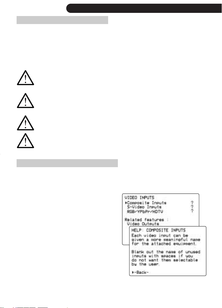
video inputs configuration....................................................49
RGB / HDTV input signal configuration .................................49
DVI / HDMI inputs..............................................................50
analog audio inputs configuration ........................................50
digital audio input configuration...........................................53
TAGtronic Sync Link configuration ........................................54
when to use height speaker .................................................55
5.1 analog bypass configuration..........................................56
source input key assignments on remote ................................57
loudspeaker definition and calibration ..................................58
mode dependent speaker trims.............................................60
distance between back speakers ..........................................60
subwoofer types .................................................................61
bass redirection rules ..........................................................62
speaker calibration.............................................................63
alternative listening position.................................................63
5.1 replay through 7.1 loudspeakers....................................64
65 TMREQ TAG McLaren Room EQ

65 output options
main zone / zone 2 configuration........................................66
mute configuration..............................................................66
Dolby Headphone ..............................................................66
Dolby Pro Logic IIx configuration ..........................................67
NTSC/ PAL latency offset.....................................................68
PSM192 video output format ...............................................68
OSD on composite and S-video............................................68
69 PSM192 progressive scan module
PSM192: configuration .......................................................69
PSM192: settings ...............................................................70
PSM192: in AV192R and DVD32 ........................................71
71 VSM2048 video scaler
VSM2048: video outputs.....................................................72
VSM2048: configure video inputs ........................................76
VSM2048: picture in picture................................................78
79 FM radio
82 DAB digital radio
85 clock setting
86 action switches: relay and trigger
88 standby / wakeup timer
89 RS232 / IR TX controller | RS232 controller
RS232 settings ...................................................................91
IR learning.........................................................................93
macros..............................................................................97
macros: an example ...........................................................98
macro: RS232....................................................................99
macro: RC 5 / TAGtronic Bus.............................................100
macro: learnt IR / chaining ................................................101
change bus ID ..................................................................102
31 xxx macros .................................................................103
cursor key functions...........................................................104
control via a PC................................................................105
106 TAGtronic Bus
in and out of standby ........................................................106
sending remote commands via AV192R ..............................107
synchronising brightness....................................................107
controlling (multiple) amplifiers ...........................................107
corresponding with DVD32/DVD192 & T32R .......................112
113 hardware and software upgrades
how to enable a new software option .................................114
programming the remote ..................................................115
upgrading the AV192R’s software ......................................119
123 connecting AV192R to DVD32 with PSM192
124 running in, warming up, cleaning and service
125 standards acknowledgements
contents
|
3
SUB CENTRE RIGHT LEFT
12FM
75 OHM
DAB (50 OHM)
TAPETAPE
OUT
AUX TUNER SAT VCR TV
ANALOG INPUT
L
R
LRLRLRLRLRL
R
SUB CENTRE RIGHT LEFT
5.1 BYPASSNE 2
LEFT S L S R
7. 9.
10.
8.
18.
35.
19.
36.
20.
24.
VSM2048 POWER
|
HDTV
SB L SB R SURR R SURR L
made in United Kingdom
PROCESSED DVI - OUT
RS 232 - IN RS 232 - OUT
DVI - IN1 DVI - IN2
Double insulated: When servicing,
use only identical replacement parts
IR - TX
COMPONENT/RGB IN
BALANCED ANALO
B1R1S1
G1
B2R2S2G2B3R3S3
G3
B
H
G
V
serial number
COMPONENT/RGB OUT
R
Y … G
P
b … B
Pr … R
CAUTION
RISK OF ELECTRIC SHOCK
DO NOT OPEN
220-240V
~ 50-60Hz
Fuse: T1A L250V
OUTIN
ABCDE
BUS
IN/OUTOUT
ZON
RIGHT
ANALOG OUTPUT
RIGHTSUB
LEFTCENTRE
DIGITAL AUDIO
DVD192
OPTICAL
OUT
SAT D BOXDVB
DVD CD
SYNCDAB
MD
LD
COMP-C D BOX-C TV-C
COMPOSITE
SAT-C
LD-C
DVD-CVCR-C
SAT-SLD-S
DVD-SVCR-S
D BOX-S TV-S
S-VIDEO
REMOTE
OUTIN MIC
ACTION SWITCHES
SURR L
SURR R
OUT
OUT +OSD
OUT
OUT +OSD
COAX OUT
2/RF
BACK L BACK R
analog
digital
video
zone 2
surround
THX Cinema
mute/standby
display
normalok
THX Surr. EX
DTS-ES
DTS 96/24
zone 2/
av processor AV192R
192
7•1
1. 4.
6.
3.
5.
2.
RCAM-s CAM-c CAML RS232
15.
14.
30.
16. 17.
34. 31. 32. 33. 29. 28. 27. 26. 25.
13.
12.
a.
11.
b. c. d. e. f.
21.
37. 38. 41. 42.39. 40. 43
22. 23.
RCAM-s CAM-c CAML RS232
controls
controls
|
54
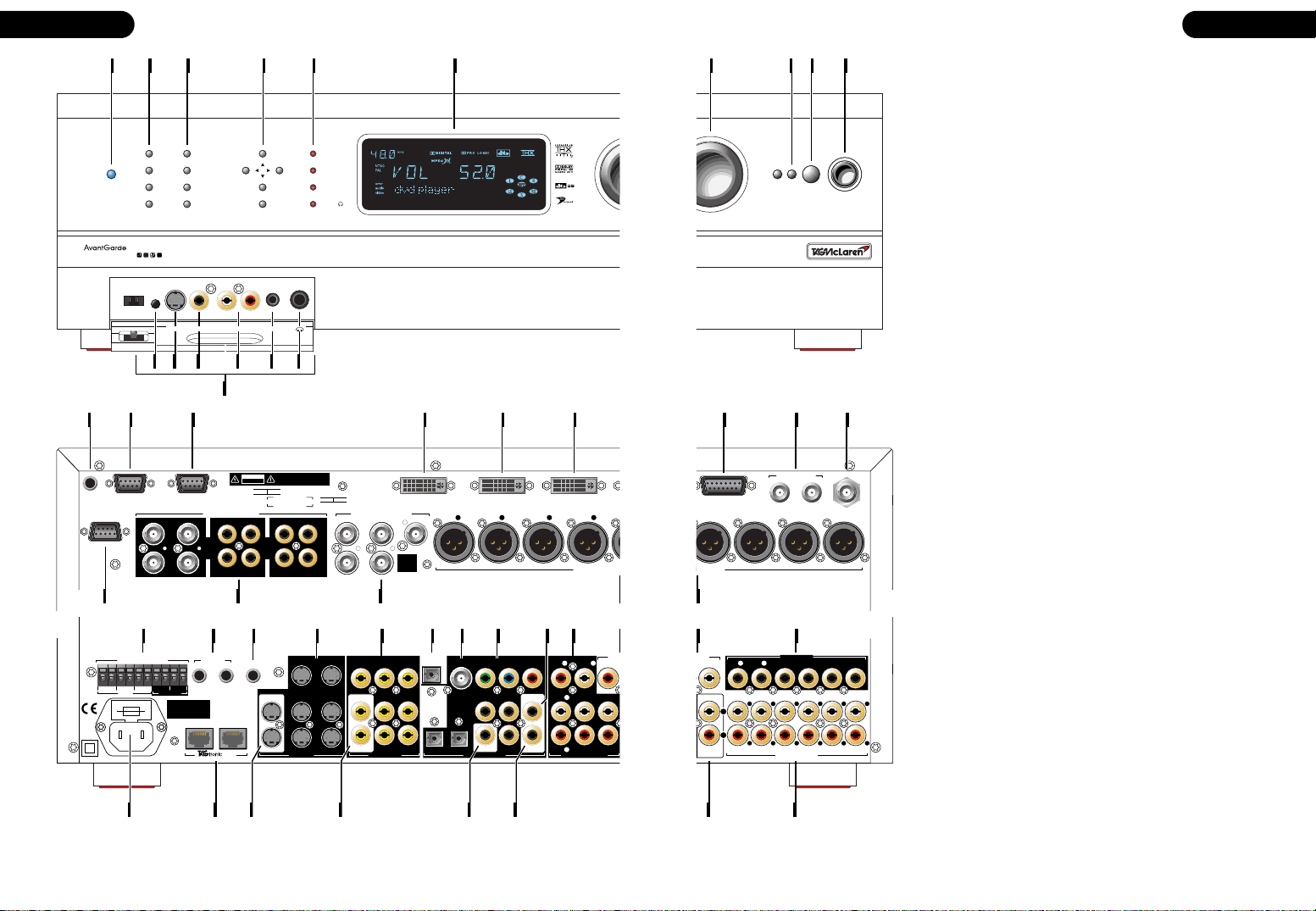
1 power / standby indicator
2 input / zone 2 selection buttons
3 mode / standby buttons
4 function buttons
5 flag / zone 2 indicators
6 display
7 volume knob
8 remote command acknowledge indicator
9 remote command receiver window
10 power button
11 front panel electronics - option
a infra-red receiver for use with RS232/IR TX controller option
b S-video input CAM-S
c composite video input CAM-C
d analog stereo input CAM
e RS232 programming input
f headphones output
12 infra-red receiver output - RS232/IR TX controller option
13 RS232 input - RS232/IR TX controller option
14 RS232 output - RS232/IR TX controller option
15 DVI output - PSM192 or PSM192/VSM2048 option
16 DVI input - VSM2048 option
17 DVI input - DVI switcher option
18 PSU input - VSM2048 option
19 FM 1 / 2 antenna inputs - FM radio option
20 DAB digital radio antenna input - DAB digital radio option
21 HDTV video input - RGB/Component switcher option
22 RGB / Component inputs - RGB/Component switcher option
23 RGB / Component output - RGB/Component switcher option
24 balanced/XLR analog audio outputs - option
25 action switches
26 input/output for electrical ‘infra-red’ distribution system
27 microphone input - for future use
28 S-video inputs
29 composite video inputs
30 optical digital audio output
31 DVD192 - BNC based digital audio input
32 digital audio inputs
33 1st digital audio output
34 analog audio outputs
35 zone 2 - analog audio outputs
36 5.1 analog bypass
37 AC connection with fuse holder, above
38 TAGtronic communication bus
39 S-video outputs
40 composite video outputs
41 TAGtronic Synchronisation Link connector
42 2nd digital output or AC-3 RF Laserdisc input - option
43 tape output
44 analog audio inputs
Specification shown may vary for different countries

|
6
welcome
welcome to
Dr. Udo Zucker
Chief Executive Officer
TAG McLaren Audio
TAG McLaren Audio exists with one aim in mind: to
produce the very best audio and audio-visual equipment
in the world.
Like many people, I often have my best ideas when
relaxing to a piece of music or watching a movie. For
years, knowing the technical capabilities of TAG
McLaren, I have nurtured the ambition to push music
reproduction to the absolute limit; that’s why we formed
TAG McLaren Audio.
At the core of our development team are highly
experienced engineers whose heritage of award-winning
hi-fi and world-beating electronic control systems is
envied by many and equalled by few.
There are many immediate spin-offs into audio from our
expertise in automotive electronics, mechanical
engineering and the material science of Formula One
motor racing: multi-layer printed circuits, fast digital
signal processing, electronic noise suppression, radio
frequency technology and software expertise to name but
a few - all prerequisites of an outstanding audio product.
TAG McLaren Audio’s aim is perfection combined with
aesthetic delight and solid build quality – a rare
combination in hi-fi.
I am convinced it will give your home cinema experience
a new dimension.
Enjoy ...
Dr. Udo Zucker
safety first / when you need additional assistance
safety first
before you start
Make sure that all components of your audio-visual system are disconnected from the AC
supply whenever you change any connections. The power button is a latching switch. One
press will hold it in; the next will release it. Check that the power button is out so that power
is off.
positioning
The AV192R is designed to run warm during normal operation. Please ensure that
there is adequate ventilation above and below the unit. We recommend that you do
not place your AV192R near any heat sources such as radiators or in direct sunlight.
Do not expose your AV192R to dripping or splashing liquids. Do not place objects
filled with liquid, such as vases, on or near it.
Do not place your AV192R on top of any electronic product (or hot surface), it will
warm both products because of restricted ventilation.
Do not connect the AC cable, supplied, until you have completed all connections.
when you need additional assistance
|
7
To maximize the performance from your AV192R, it is essential to configure it correctly.
This will ensure it performs its role at the heart of your home cinema system to its optimum.
Without this set-up you will significantly reduce your system’s potential.
In case you need any support, remember:
• refer to the on screen help, available from
the on screen display
• ask your TAG McLaren Audio retailer for
assistance
• contact our Helpdesk@tagmclaren.com
by email, using either the English or
German language
• refer to the Discussion Forum at
www.tagmclaren.com to share your
specific issue with others
For on-line help select the ? using the
cursor keys, followed by ok
1. Throughout the manual, bold print indicates the lettering that you will find on the panels of your AV192R or the remote.
(1)
.
|
8
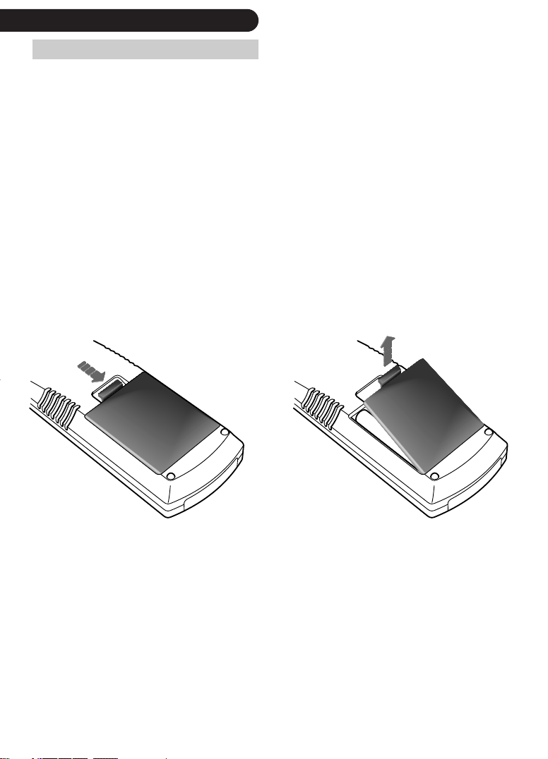
preparing the remote control
installing batteries
The AV192R is supplied with a ‘learning’ remote. This is supplied
pre-programmed for TAG McLaren Audio home cinema products,
but may easily be re-programmed to control other devices using
an infra-red remote within your home audio and audio-visual
system. The remote uses four AAA 1.5 V batteries. These are
supplied with the AV192R.
To open the battery compartment, push the latch forward towards
the top of the remote, and lift the latch up. Make sure that
batteries are inserted in the correct orientation, with the + and –
markings on the batteries match those in the battery
compartment
To close the battery cover, slide it straight back in (towards the top
of the remote) and push down until it clicks into place.
(1)
.
1. Make sure you do not press any keys on the remote during battery changing, as you will lose any user- programmed functions. For more
information about programming the remote, please refer to page 87 ‘programming the remote’.
connectivity: audio sources
Please have a look at the rear panel of your AV192R and under its front panel flap
(1)
|
and you will
see many potential connections can be made to your AV192R. Fortunately these connections can
be separated in logical groups which are described in the following paragraphs:
audio inputs
You can connect analog (stereo and 5.1) and digital audio signals.
9
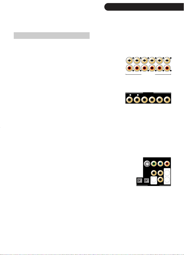
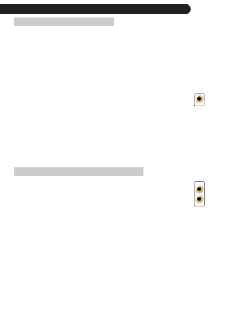
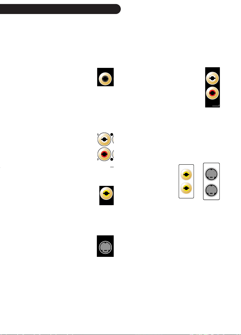
stereo analog inputs
Your AV192 has six, electrically identical analog inputs at the
rear, labelled for convenience TV, VCR, SAT, TUNER, AUX,
TAP E. There is an additional analog input at the front, CAM, if
your AV192R is fitted with the front panel flap.
5.1 bypass
The AV192R offers a 5.1 BYPASS, which is also
configurable as three stereo inputs. The 5.1 BYPASS is a
true 5.1 analog bypass with analog volume control,
allowing the direct connection of DVD Audio or multichannel SACD players.
All analog inputs use phono sockets and should be connected using
good-quality, screened, analog audio cable, such as our Cable
AvantGarde analog interconnect.
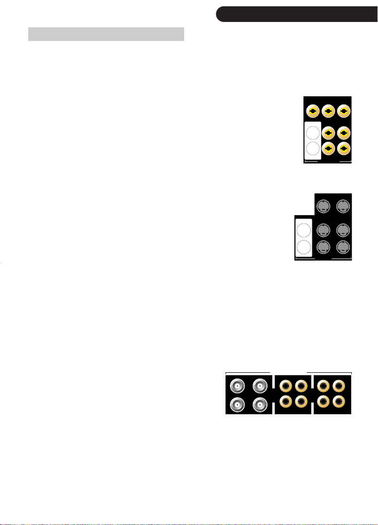
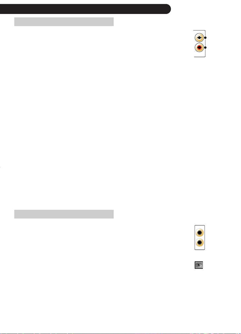
SPDIF digital audio inputs
Your AV192R has nine digital audio inputs using the SPDIF interface
standard. They are labelled for convenience DVD192, SAT, DVB, D
BOX, DVD, CD, LD, MD and DAB.
The inputs labelled SAT, DVB, D BOX, DVD, CD, and LD use phono
sockets and should be connected using a digital cable.
Input DVD192 use a 75 Ohm BNC connector for best impedance
matching, resulting in improved sound quality.
LRLRLRLRLRL
AUX TUNER SAT VCR TV
TAPE
Signals connected to the 5.1 Bypass
will not be digitised, therefore no
processing beside analog volume
control will be possible.
ANALOG INPUT
5.1 BYPASS
S L S R
SUB CENTRE RIGHT LEFT
DVD192 SAT D BOXDVB
MD
DIGITAL AUDIO
DVD CD
SYNCDAB
COAX OUT
LD
2/RF
R
The inputs DAB and MD use optical TOSLINK connectors.
Cable AvantGarde offers good-quality, screened, coaxial digital
interconnects with phono and BNC connectors or a combination of both.
1. If fitted.
|
10
connectivity: TAGtronic Sync Link / AC-3 RF Laserdisc
TAGtronic Sync Link
(1)
‘T2L’
The stability of the timing of digital data has a dramatic effect on
sound quality. When designing digital to analog converters, it is
vital to have a stable digital clock as close to the converter
electronics as possible. The best place for an ultra-low-jitter clock is
within the audio-visual processor itself, but it is conventionally
located in the source from which the digital data is sent.
The AV192R incorporates sophisticated electronics which enable it
to ‘drive’ the source clock of products equipped with this technology
to provide the correct data rate to the converters. By a process
called ‘re-clocking’, the jitter in the digital audio data is dramatically
reduced.
To enable this feature, the TAGtronic Sync Link SYNC connector must
be connected to the appropriate SYNC connector of the digital
audio source using a high-quality analog interconnect.
The sync output software must also be enabled using the on-screen
set-up menu system, for details see page 54.
connectivity: AC-3 RF Laserdisc interface
If you want to play NTSC Laserdiscs encoded in Dolby Digital, you
will need the optional AC-3 RF interface. This interface converts the
Radio Frequency (RF)-encoded information stored on the Laserdisc
into an SPDIF-compatible Dolby Digital bitstream, allowing the
AV192R then to decode this data in the same way as if the signal
had come from a DVD encoded with Dolby Digital.
SYNC
COAX OUT
2/RF
If the AC-3 RF Laserdic interface option is installed, it uses the phono
connector COAX OUT2/RF
1. When the interface is not fitted, this socket is available as a second coaxial COAX OUT 2/RF
(1)
as the AC-3 RF input.
connectivity: video sources
video inputs
The AV192R can process analog Composite video, S-video and, if the optional RGBS /
Component Video Switcher is fitted, RGB / Component video. In addition, it can process
digital video DVI (1.0) if the optional DVI/HDMI Switcher is fitted. For more details see
page 50.
Composite video
The AV192R has seven 75 Ohm Composite video inputs at the rear,
labelled for convenience COMP-C, D BOX-C, TV-C, VCR-C, DVD-C, LD-C
and SAT-C. There is an additional input at the front, CAM-C, if the AV192R
is fitted with the front panel flap.
All inputs, except SAT-C are electrically identical - SAT-C has been modified
to accept video signals with high DC offset, a signal degradation found in
some satellite receivers.
S-video
The AV192R has six 75 Ohm Mini-DIN S-video inputs at the rear, labelled
for convenience D BOX-S, TV-S, VCR-S, DVD-S, LD-S and SAT-S. There is
an additional S- video input at the front, CAM-S, if the AV192R is fitted
with the front panel flap.
All inputs, except SAT-S are electrically identical - SAT-S has been modified
to accept video signals with high DC offset, a signal degradation found in
some satellite receivers.
COMP-C D BOX-C TV-C
OUT
OUT +OSD
OUT
OUT +OSD
S-VIDEO
COMPOSITE
D BOX-S TV-S
|
11
DVD-CVCR-C
SAT-C
LD-C
DVD-SVCR-S
SAT-SLD-S
Component video
The AV192R can be equipped with a 3 to 1 RGBS / Component video switcher. This allows
the switching of up to three RGBS/Component video sources to a common video output,
usually the display device. In addition, the RGBS Component Video Switcher includes an
HDTV (HD15) input which can also be routed to the output.
The AV192R offers full support of RGBS, i.e. RGB with separate Sync, which is very common
in Europe. It works equally well with YPbPr,
common in the USA.
G1
COMPONENT/RGB IN
G2B3R3S3G3
Two of the input sets (R2, G2, B2, S2 and R3,
G3, B3, S3) use digital RCA, whilst for added
performance the third set (R1, G1, B1, S1) is
assembled with 75 Ohm BNC connectors for
true impedance matching, essential for high
B1R1S1
Component Video YPbPr is connected as
follows: Y->G, Pb->B and Pr->R
B2R2S2
frequency signals.
All signals can be passed through the optional Progressive Scan Module
PSM192 and the optional Video Scaler VSM2048, offering YPbPr, RGsB
or RGBHV as output formats. For details see pages 68 and 73.
|
12
heading12|connectivity: main zone / zone 2/ XLR balanced outputs
audio outputs
The AV192R offers 7.1 channels in the main zone and two channels in zone 2.
main zone connections
The RIGHT, CENTRE, LEFT, SURR R, SURR L, BACK R, BACK
and SUBwoofer phono outputs are low-impedance line-level outputs,
buffered to be able to drive long cables or several inputs in parallel
if required. These should be connected to your amplifier(s) using
good-quality, screened, analog audio cable such as our Cable
AvantGarde F3-10-ANA analog interconnect.
L
SURR L
SURR R
ANALOG OUTPUT
BACK L BACK R
LEFTCENTRE
RIGHTSUB
zone 2 connections
ZONE 2
Zone 2 allows for ZONE 2 RIGHT and LEFT, being an independently
RIGHT LEFT
volume controlled copy of the corresponding signals ANALOG OUTPUT
RIGHT and LEFT of the main zone.
The ZONE 2 RIGHT and LEFT phono outputs are low-impedance line-level outputs, buffered to
be able to drive long cables or several inputs in parallel if required. These should be
connected to your amplifier, used for zone 2, using good-quality, screened, analog audio
cable such as our Cable AvantGarde F3-10-ANA analog interconnect.
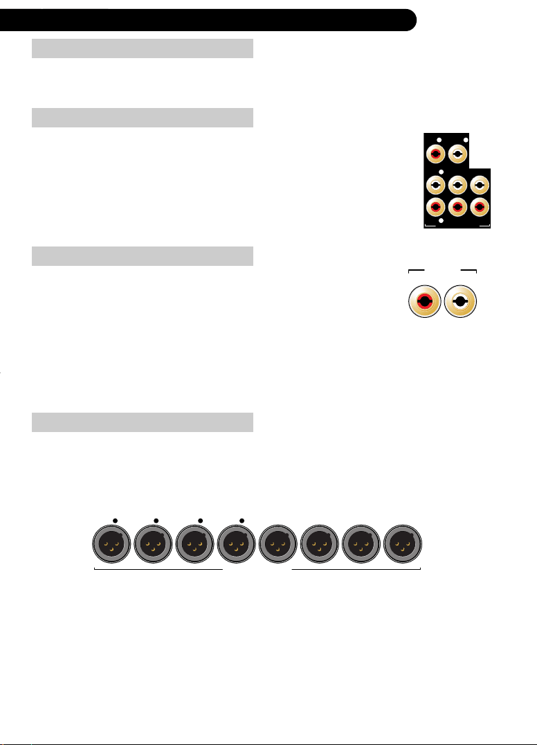
balanced analog outputs
The AV192R can be upgraded to provide balanced XLR outputs. These are in addition to the
standard single-ended outputs. Both single-ended and balanced outputs can be used at the
same time and have been calibrated to offer identical amplification, making them also suited
for bi-amplification set-ups.
SB L SB R SURR R SURR L SUB CENTRE RIGHT LEFT
BALANCED ANALOG OUTPUT
why should you add the XLR option
It is possible for a current to flow between the ground connections of the AV192R and its
connected power amplifiers, caused by electro-magnetic interference or ground potential
differences. With a single-ended connection this current is indistinguishable from the signal
and hence can become audible as a hum or buzz. The problem is usually referred to as
ground loops and can be overcome by using balanced outputs driving an amplifier’s
balanced inputs. This option is recommended for those who experience ground loop
problems or simply want the best signal to noise ratio.
heading
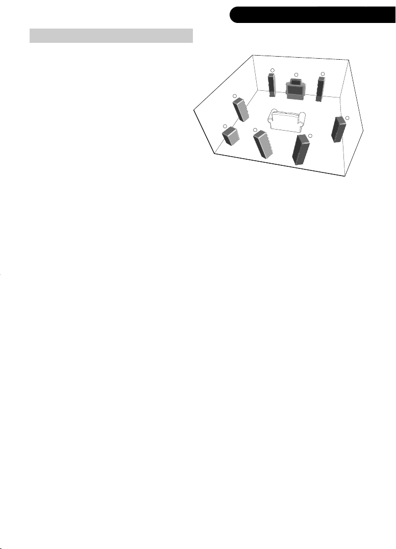
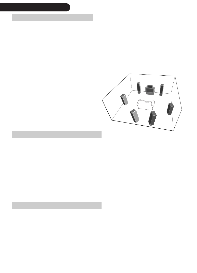
speaker positioning
With the exception of the subwoofer
and the height channel speaker, all
loudspeakers should be arranged
around your normal viewing / listening
position, forming an approximate
3
circle. Do not worry if you are unable
to position your loudspeakers at equal
distances from your preferred listening
5
position, the AV192R can be set up to
take account of different distances. The
subwoofer can be placed almost
anywhere, but we recommend you
experiment to obtain the best results.
1. front left and right loudspeaker
Position your front loudspeakers so as to obtain a good stereo image for normal music reproduction as
well as good sound location for multi-channel modes
2. centre loudspeaker
A front centre loudspeaker allows more realistic reproduction of dialogue and central sounds and a wider
range of seating positions. The centre loudspeaker should ideally be placed at the same height as the left
and right loudspeakers, immediately above or below the television. Do not compromise on the quality of
the centre loudspeaker; it is most important to a good home cinema system as it carries all the dialogue.
3. surround loudspeakers
‘5.1’ home cinema uses one or preferably two rear loudspeakers in addition to your existing front left,
right and centre loudspeakers to give excellent reproduction of ambient sound and cinema effects.
4. back channel loudspeaker
Your AV192R allows you to add one or two back channel loudspeakers for added depth, spacious
ambience and sound localization. You might need to move your standard left and right surround
loudspeakers forward in order to generate the most impressive surround sound. Place the loudspeakers to
have the sound perfectly surrounding you without ‘breaking up’ when moving from one surround speaker
to the other.
5. subwoofer
Bass performance will be improved by adding a subwoofer. This is useful for reproducing special cinema
effects, especially where a dedicated LFE (Low-Frequency Effects) channel is available, such as with Dolby
Digital or DTS Digital Surround-encoded discs.
6. height channel loudspeaker
The AV192R is one of the first processors offering a height channel, making sure that sound intended to fly
over you, will no longer fly through you.
Movies especially mixed with height channel information, and many mixed in THX Surround EX (Dolby EX)
or DTS-ES 6.1 will benefit from this enhancement
Information, intended for the height channel, is matrix encoded in the surround back and centre channel. If
you activate the height channel, the BACK RIGHT SURR. output will be assigned to the output of the height
channel matrix decoder.
If you want to run two back channels in addition to the height channel, then you need to connect both
back channel loudspeakers via two power amplifier channels to BACK LEFT SURR.
(1)
(1)
.
1
4
1
2
4
|
13connectivity: loudspeakers|13
3
1. THX Surround EX (Dolby EX) and DTS-ES 6.1 recordings provide an additional back channel, which the AV192R can route to go to a left
and right surround back speaker, if the height channel is not activated.
|
14
connectivity: analog and digital tape connections
analog tape output
The TAPE OUTput contains a copy of the audio signals routed to the
RIGHT and LEFT front channel outputs, without applying volume control
or mute. Connect the recording input of an analog tape recorder to
TAPE OUT if you want to record the signal of the RIGHT and LEFT front
channels.
caution when pressing the tape key/button during
recording
If you listen to an analog stereo input, pressing the tape key/button
will route the TAP E input to the ANALOG OUTPUTs without
changing the signal going to TAPE out, allowing for example, the
recorded signal to be compared with the original whilst recording
using a three-head tape recorder (if its output is connected to TAP E).
In this instance the front display will show TAPE (name of analog
input routed to TAPE out), e.g. TAPE(SAT). Pressing tape again will
return to the analog signal selected before tape was pressed the
first time.
If however, you record the result of a digital audio input, e.g. CD,
or the 5.1 BYPASS then you should not press the tape key/button
whilst recording, as this will route the TAP E input to the ANALOG
OUTPUTs and TAPE OUT, spoiling your recording. This behaviour
will be shown in the front display by the word TAP E. Pressing tape
again will return to the digital input/5.1 BYPASS selected before
pressing tape the first time.
L
R
TAPE
OUT
digital (tape) output
The signal at COAX OUT 2/RF (if the optional AC-3 RF interface isn’t
installed- see page 10) and OPTICAL OUT is an unmodified copy of
the currently selected digital audio source, i.e. it is unaffected by the
volume control or processing mode.
The digital coaxial COAX OUT or the OPTICAL OUT (TOSLink)
should normally be connected to your digital recording device (such
as a DAT or MD recorder).
It is not possible to route an analog source to the digital coaxial
outputs.
COAX OUT
2/RF
OPTICAL
OUT

heading
TAGtronic Bus routing
The AV192R features the TAGtronic Communications Bus. This allows TAG McLaren Audio
units to work together seamlessly to form an effective, fully integrated system. It is highly
recommended to connect products, featuring the TAGtronic Bus together, as many additional
features will become available.
Details are explained on page 106.
You can connect your AV192R to the TAGtronic Bus using a ‘straight’ CAT5 cable with RJ45
connectors. Straight means pin 1 of the connector on one end, connects to pin 1 of the
connector on the other end. CAT5 cable is available from your local computer shop at a
reasonable price.
The sequence is in principle of no relevance as long as you connect an output to an input
and don’t close the Bus to be a ring. For example:
[AV192R] Out
In [100x5R 1st amplifier ] Out
In [100x5R 2nd amplifier ] Out
In [DVD32] Out
|
15connectivity: TAGtronic Bus / FM & DAB digital radio|15
In [T32R]
Do not close
back to AV192R
FM & DAB digital radio
The AV192R can be equipped with an optional FM radio and / or
an optional DAB digital radio.
The FM radio option provides two, electrically identical 75 Ohm
(1)
PAL
antenna inputs, FM1 and FM2, allowing e.g. the connection of
an out-door antenna and a cable distribution system. For details
about the operation of the FM radio option see page 79.
The DAB digital radio, featuring band III and L reception, uses as
antenna input a 50 Ohm BNC connector, labelled DAB (50 OHM).
For details about the operation of the DAB digital radio option see
page 82.
1. For a number of countries, an F-type connector is fitted.
12FM
75 OHM
DAB (50 OHM)
|
16
connectivity: RS232- IN / OUT & IR-TX
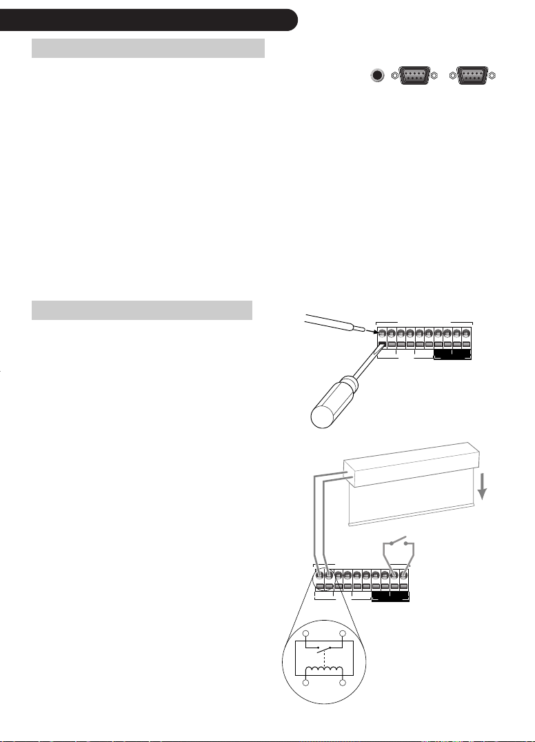
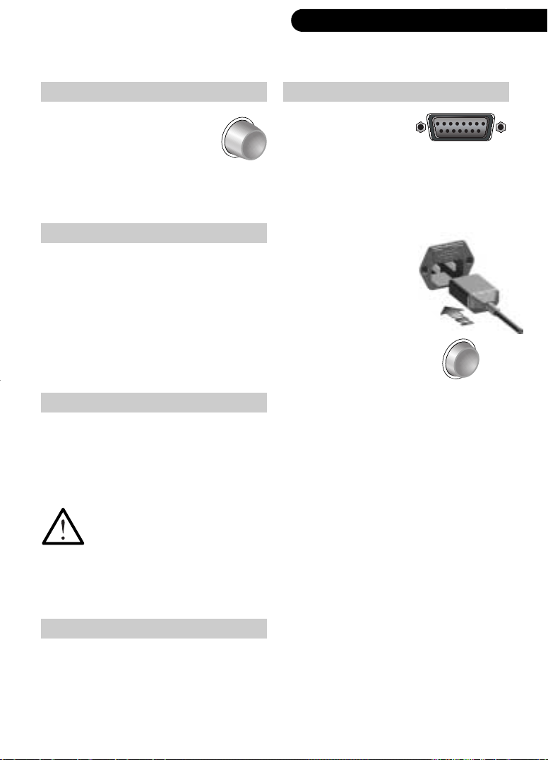
RS232/IR TX controller connections
The connectors shown belong to the optional RS232/IR TX
controller which allows an unprecedented degree of automation.
IR - TX
RS 232 - IN RS 232 - OUT
The RS232/IR TX option is a self contained microcontroller-based module with advanced
input and output facilities. It opens up a whole new world of system integration and control
for AV192R. The board provides RS232 input (RS232-IN) and RS232 output (RS232- OUT)
connectors, an electrical IR output (IR-TX) to connect an IR emitter and an IR input, for
learning IR codes, via a sensor located under the front panel flap, left of the CAM-s
connector.
With the RS232 board fitted the AV192R gains the ability to control 3rd party products,
either via RS232 or IR.
For more details see page 89.
action switches
Action switches are used to activate external
events or to react to external events, such as
lowering a motorised screen or showing a
Insert screwdriver
to open contact,
then push wire
into contact.
ACTION SWITCHES
ABCDE
1212121212
IN/OUTOUT
message on-screen when the door bell rings.
The AV192R includes five ACTION SWITCHES,
two of which can also be configured as a
trigger. All Action Switches are located within
a contact array, making both contacts of each
internal switch available to the user.
Motorised Screen
The AV192R includes switches A, B, C (and D,
E if configured as output) which are controlled
(opened/closed) by the AV192R when
selecting an input source or when switching the
AV192R into standby.
Switch D and E can also be configured as a
trigger, i.e. they can activate a process within
the AV192R, when an electrical signal is
applied.
A description of the AV192R’s Action Switch
ACTION SWITCHES
ABCDE
internal circuitry
12
E is configured in this
skecth as an input,
1212121212
i.e. closing the circuit
between E1 and E2
will trigger an event
IN/OUTOUT
inside the AV192R
configuration menu can be found on page 86.
Relay controlled
by AV192R
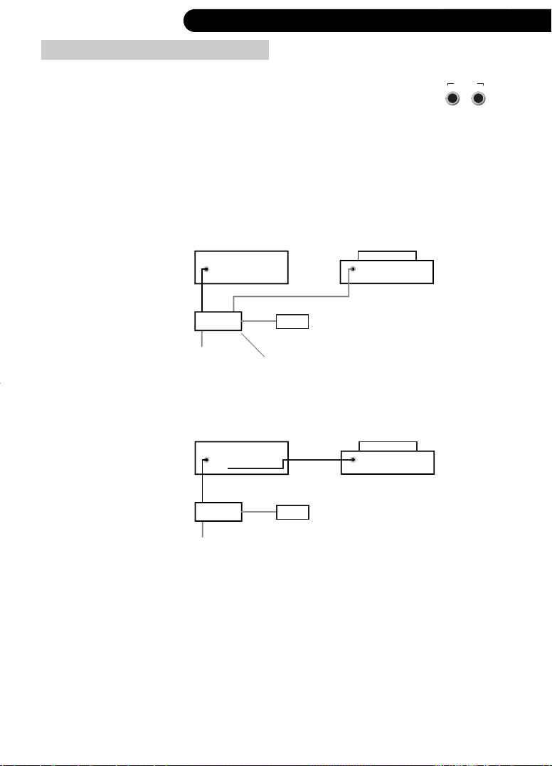
external IR receiver connections
heading
|
17connectivity: electrical ‘IR’ distribution system|17
The AV192R ‘7.1’ includes two sockets at the rear panel, named
REMOTE IN and REMOTE OUT. They can be used to place the AV192R
‘7.1’ out of sight when connected to a wired infra-red remote system.
Example Layout
Attention: Some IR distribution systems can only connect one product per sensor
output. In this instance use only the REMOTE IN connector.
IN
AV192R
A
power
B
IR
sensor
IR distribution system
Use this arrangement for IR distribution systems which allow product chaining, for
details contact your IR distribution system manufacturer.
IN
OUT
AV192R
IN
IN
REMOTE
OUTIN
e.g. DVD32R
e.g. DVD32R
A
power
B
IR
sensor
|
18
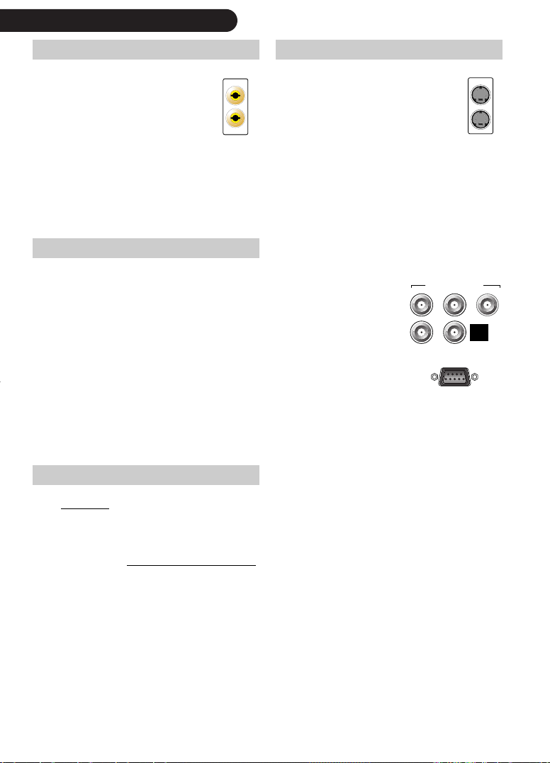
connectivity: video outputs
composite video S-video
The AV192R can route any of its
Composite video inputs to a pair
of COMPOSITE video outputs,
labelled OUT and OUT+OSD.
OUT
OUT +OSD
The AV192R can route any of its
S-video inputs to a pair of S-
VIDEO outputs, labelled OUT and
OUT+OSD.
OUT +OSD
The output OUT+OSD allows the AV192R to insert text on your TV (On-Screen Text = OSD)
when required. This output should be connected to your display device. You should use the
output OUT where you will never want to see the inserted text, such as on a VCR.
RGB / component video
The AV192R can be optionally equipped with a 3 to 1 RGBS /
Component video switcher. This allows the switching of up to three
RGB / component video sources to a common video output. In
addition, the RGBS Component Video Switcher includes an HDTV
(HD15) input which can also be routed to the output.
The AV192R offers full support of RGB, RGBS (RGB with separate
Sync) and YPbPr USA.
There is no video conversion between these formats and no OnScreen text available, except if the optional Progressive Scan
Module PSM192 is installed.
COMPONENT/RGB OUT
R
B
G
H
HDTV
digital video DVI
V
Y … G
P
Pr … R
OUT
b … B
All interlaced video inputs are also available in digital form on the
PROCESSED DVI-OUT connector, using DVI 1.0, if the AV192R is
equipped with the optional Progressive Scan Module PSM192.
All video inputs, interlaced or de-interlaced
, are available in digital form
on the PROCESSED DVI-OUT connector, using DVI 1.0, if the AV192R is
equipped with the optional Video Scaler VSM2048.
The DVI output offers on screen display, as described on the next page,
but only in full screen mode and if the video source was interlaced.

heading
|
on-screen display
The AV192R’s on-screen display (OSD) superimposes text on the picture for a few seconds
whenever a change occurs, such as when you select a new input or change the volume. You can
change how long the text remains for, as well as the position of the text on the screen, or turn this
function off altogether, pressing menu, then select Change Set-up, Displays, On- Screen Display.
OSD is available
• for composite video sources on COMPOSITE OUT+OSD
• for S-video sources on S-VIDEO OUT+OSD
• for interlaced Component sources on COMPONENT/RGB OUT - if the optional Progressive
Scan Module PSM192 is installed
• for interlaced video in full screen mode on PROCESSED DVI-OUT if the optional Progressive
Scan Module PSM192 is installed
As soon as text is not required, the OSD electronics are switched out of circuit to maintain a
‘straight-though’ video path, i.e. the video signal quality is not affected.
For details on how to configure the OSD, see page 48.
The AV192R can only generate OSD for interlaced video sources.
19on-screen display / video conversion|19
video standard and signal conversion
The AV192R does not convert between composite, S-video and component video, except when
the optional Progressive Scan Module PSM192 is installed.
All video signals, composite, S-Video or Component video can be passed through the
optional Progressive Scan Module PSM192 (and the optional Video Scaler VSM2048)
offering YPbPr, RGsB or RGBHV as video output formats.
All interlaced
connector, using DVI 1.0, if the AV192R is equipped with the optional Progressive Scan
Module PSM192.
All video inputs, interlaced or de-interlaced, are available in digital form on the
PROCESSED DVI-OUT connector, using DVI 1.0, if the AV192R is equipped with the
optional Video Scaler VSM2048 and its optional Analog Input Module.
If you want to use composite, S-video and component video sources- and you do not have the
optional Progressive Scan Module PSM192 installed - you must connect all signals to your
display device.
video inputs are also available in digital form on the PROCESSED DVI-OUT
|
20
basic system set-up: an example
The following is a basic configuration, reflecting one of many
configurations. It assumes that the AV192R does not include/use the
optional RGBS/Component Switcher, Progressive Scan Module, DVI
Switcher or Video Scaler VSM2048.
digital audio source
connect the digital audio output
of a DVD player (probably
labelled ‘coaxial out’ or ‘coaxial
digital out’) to the DIGITAL
AUDIO input DVD using a digital
interconnect cable
analog audio source
connect the analog audio output
of a satellite receiver (probably
labelled ‘left’ and ‘right’) to
the ANALOG INPUT SAT Land
SAT
R
composite video
connect the composite video
output of a satellite receiver
(probably labelled ‘video’ or
‘composite’) to the COMPOSITE
input SAT-C
S-video connection
connect the S-Video output of a
DVD player (probably labelled
‘S-Video’) to the S-VIDEO input
DVD-S
DVD
SAT
INPUT
SAT-C
DVD-S
connection to the power amplifier(s)
this sample configuration is
limited to a stereo set-up only:
connect the AUDIO OUTPUT LEFT
(RIGHT) to the power amplifier
used for the left (right) front
loudspeaker
Connect the left and right front
loudspeaker to your power amplifier(s) as
outlined in your power amplifier's user
L
manual
tv connection
R
(1)
connect the
composite input of
your TV to the
AV192R using the
COMPOSITE
OUT+OSD and the
TV’s S-Video input
to the S-VIDEO
OUT+OSD socket
There are many potential system
set-ups. Please refer to page 7 to
learn how to get assistance in
achieving your dream system.
OUT
OUT +OSD
LEFT
RIGHT
PUT
OUT
OUT +OSD
1. You need to connect both COMPOSITE OSD+OSD and S-VIDEO OUT+OSD to your display device if you connected source components via
a composite and S-Video connection.
heading
The following assumes that you have connected all your sources, audio and video, your
loudspeakers and your display device to your AV192R.
|
21switching on / standby / clock|21
power connection
Check that the power button is
out so that power is off when
you plug in. The power button
is a latching switch. One press
will hold it in, the next will release it. Using
the cable supplied, connect the socket on the
back of your AV192R to an AC supply outlet.
Scaler PSU connection
If your unit has the
VSM2048 option,
connect the power
lead from the VSM
power supply to the PSU input on the rear
of the AV192R, and connect the power
supply to an AC supply outlet.
VSM2048 POWER
switching on
Press the power button in. The AV192R’s blue power LED will come on,
the display window will light up and a few seconds later will show
SELFTEST, above TAG McLaren, then the software version number such
as V4.09.00, above AV192R-GB
(1, 2)
.
All outputs are muted when the power is switched on to allow all the
voltages to stabilize. This protects the internal components of the
AV192R, amplifier and loudspeakers and prevents unpleasant switching
noises. You will hear the mute relays click, which is normal.
standby
The AV192R has a standby mode, which can be entered using the standby key on the remote
or by pressing the mute/standby button on the front panel for more than three seconds. The blue
power LED will dim, the front panel display will show ‘going to standby’ then the AV192R will
switch off
(3)
.
All circuitry essential for sound quality remains powered up in standby, meaning the
AV192R will still maintain its operating temperature and will still consume electricity. You
should power the AV192R down using the front panel mounted on/off switch if you want
to switch the AV192R off for a prolonged period
(3)
. The video outputs are also kept active
in standby mode, allowing you to watch television even when the AV192R is in standby.
Normal operation may be resumed by turning the volume knob (more than about 45 degrees) or
pressing any front panel button or remote key (other than light) at any time.
clock display in standby
The AV192R includes a real time clock, maintaining time and date, once set, even if the power
is temporarily removed. You can configure the AV192R to show the time in standby, for details
see page 85.
1. AV192R-GB indicates that the AV192R uses the English language. The AV192R might also be available with other languages. The necessary
software will be made available from www.tagmclaren.com.
2. This text will be overwritten by your personalized start-up message, for details see page 46.
3. If the AV192R is powered down using the front panel mounted on/off switch whilst in standby mode, it will go back into standby when next
switched on. In this event press the standby key to power up the unit.
|
22
controlling remotely / front panel display
controlling remotely
The AV192R is supplied with a ‘learning’ remote. This is supplied pre-programmed for TAG
McLaren home cinema products, but may easily be re-programmed to control other devices
using an infra-red remote
(1)
.
Before you can control the AV192R using the
remote, you must first select it as the device to control
by pressing the av key in the REMOTE SELECTION
area at the top of the remote. The AV192R will
remain selected by the remote until another unit is
REMOTE SELECTION
av
cd dvd
sat
tv vcr
amp
ld
chosen via the REMOTE SELECTION keys.
Once the AV192R has been selected, it can be controlled in its entirety from the remote. The
red ‘remote control active’ LED on the front panel of the AV192R will flash when commands
from the remote are received, and the av key in the REMOTE SELECTION area will light
briefly with each key press. For optimum performance from the remote you should point it
towards the remote control window on the front panel of the AV192R.
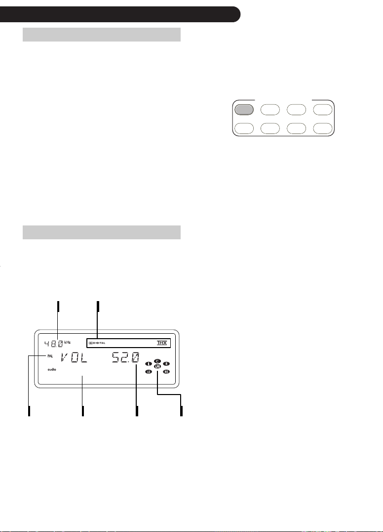
front panel display in operation
When the AV192R leaves the factory, the display will be configured similar to the one shown
below. It can be configured to your personal preference, for details see page 46.
The programme source format
indicator shows the active output
channels, i.e. channels receiving
information from the AV192R.
The sample rate indicator at the
top left of the display window
shows the sample rate of the
digital source. When an analog
source is active, it shows the
sample rate used for the analog
to digital conversion.
The display will show station
name and radio text if your
AV192R includes the FM radio
or/and DAB digital radio option
and radio is selected as the
current input.
video
standard
sample
rate
dvd player
audio
input
decoding/processing
mode
volume
setting
programme
source format
1. Please refer to the ‘programming the remote’ section on page 115 for further details on how to do this.
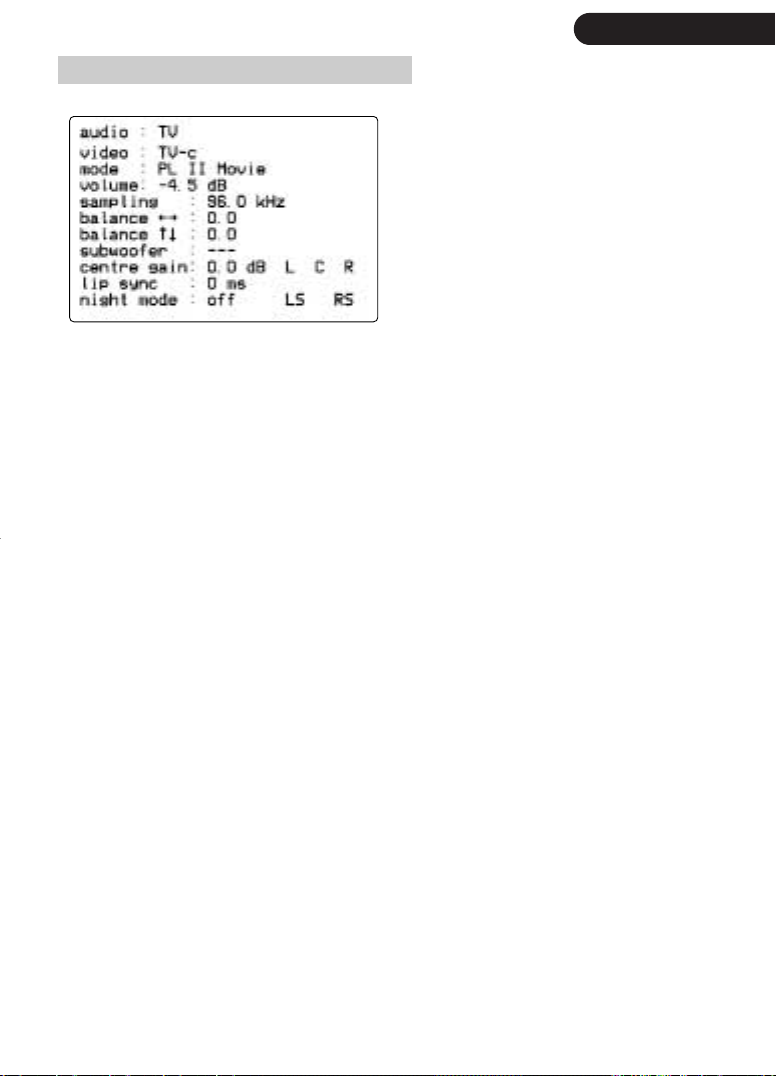
all essential user settings at a glance
the status screen might differ from the one shown,
depending on the operating mode of the AV192R
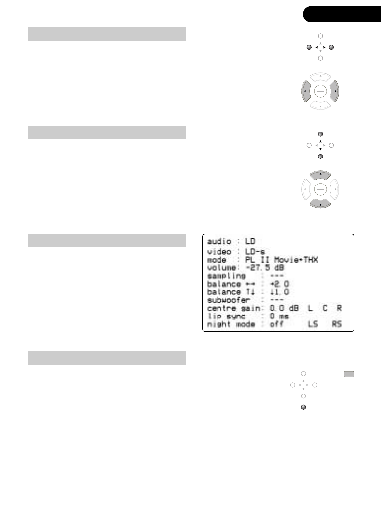
In the example above, the user has selected the analog audio input TV
and the Composite video input TV-C. The stereo signal is processed using
Dolby Pro Logic II Movie at a sampling rate of 96kHz.
The sound is replayed at a volume level of -4.5dB below reference level
(assuming the AV192R was calibrated using a SPL meter - for details see
page 63). The sound balance is as calibrated, i.e. no balance shifts
were made to the front/rear or left/right.
status screen
Pressing the ok key on the remote will bring
up a status screen which shows information
about the current operation of the AV192R
as shown in the example opposite:
|
23
There is no subwoofer in the system and hence sound is only produced
using the left/right front, centre, and the left/right surround speaker.
The time delay between picture and sound is as the incoming signals
(0 ms), for details see page 51.
The night mode is off, as it doesn’t apply to this input- it can only be
applied to DTS and DD, for details see page 45.

|
24
selecting a source
preparing the remote control
To control the AV192R via the remote press the
remote selection av key. The AV192R will remain
selected until another device, e.g. dvd is selected.
source selection
REMOTE SELECTION
av
cd dvd
sat
tv vcr
amp
ld
The AV192R remote has 11 source selection keys, labelled tv, vcr,
sat, tuner, aux, cd, ld, dvd, md, dab and tape
(1)
, to which the user
can freely assign any audio and video inputs.
Each of these source selection keys can carry two audio inputs as some
sources offer different output formats, e.g. a DVD-Audio player offers a
digital SPDIF output, when playing CDs and DVD-Video discs, but
offers 5.1 analog when playing DVD-Audio discs.
When the AV192R leaves the factory the source selection keys are
programmed to cover many installations, but you can change this ,
if you need. Please see page 57 how to change the assignment of
audio and video inputs to the source selection keys.
Scanning through all inputs, one by one
An alternative, is to scan through the analog, digital audio and
video inputs, one by one, using the analog, digital or video button
at the AV192R front fascia.
An analog (digital) input may also be selected by pressing shift
followed by, cursor up/down G/H (E/F), pressing once or
repeatedly, until the desired input is shown in the display.
A video input may also be selected by pressing once or repeatedly
the VIDEO (sometimes labelled CH) key on the remote control until
the desired input is shown in the display.
tvcdvcrldsat
10
shift
tunermdaux
dvd
dab
tape
subtitle
analog
digital
video
zone 2
pause
r
f
ok
e
f
play
w
d
stop
+
VIDEO
---
1. caution when pressing the tape key/button during tape recording
If you listen to an analog stereo input, pressing the tape key/button will route the TAP E input to the ANALOG OUTPUTs without changing
the signal going to TAPE out, allowing for example, the recorded signal to be compared with the original whilst recording using a threehead tape recorder (if its output is connected to TAP E). In this instance the front display will show TAPE (name of analog input routed to
TAPE out), e.g. TAPE(SAT). Pressing tape again will return to the analog signal selected before tape was pressed the first time.
If however, you record the result of a digital audio input, e.g. CD, or the 5.1 BYPASS then you should not press the tape key/button
whilst recording, as this will route the TAP E input to the ANALOG OUTPUTs and TAPE OUT, spoiling your recording. This behaviour will
be shown in the front display by the word TAP E. Pressing tape again will return to the digital input/5.1 BYPASS selected before pressing
tape the first time.

volume adjustment and display
volume control - main & zone 2
|
25
Volume (in the main and in zone 2) can be adjusted from 0 (very quiet) to 99 (very loud) if the
volume is configured to operate in Pre-Amp
you have configured the volume control for Cinema mode (factory setting)
In the Cinema mode the volume level of 0dB is the so-called ‘Dolby reference level’ – i.e. the
level at which a movie director intended a film to be listened
(1)
mode or -90dB (very quiet) to +15dB (very loud) if
(3)
. The ‘Dolby reference level’ in
(2)
.
Pre-amp mode is indicated by ref being shown on the OSD at a volume level of 84.
changing volume
Turn the volume knob clockwise to increase the volume or anti-clockwise to decrease the volume
in 0.5dB steps. Alternatively, you may use the VOL + and VOL – keys on the remote to increase
or decrease the volume in 0.5 dB steps per key press. If you keep the VOL + / VOL – key
pressed, the volume change per second will increase the longer you keep the key pressed.
changing zones
The AV192R can operate two independent zones, called main and zone 2. You can switch
between the zones by pressing the zone 2 button on the front fascia or preceding the volume
change request by the shift key. If zone 2 is selected, the zone 2/ LED will lit up.
main zone
Turn the volume knob or press VOL+ and
VOL- to alter the signal level of all
connected loudspeakers of the main zone,
i.e. those connected (via suitable power
amplifiers) to the ANALOG OUTPUT or
BALANCED ANALOG OUTPUT.
(4)
zone 2
If the AV192R is set to the main zone, press
shift followed by VOL+ or VOL - to switch
to zone 2 and to alter the signal level of the
loudspeakers connected to ZONE 2 RIGHT
and LEFT (via suitable power amplifiers)
outputs.
start volume
Normally the AV192R remembers the last volume setting for the main zone and zone 2 from
when it was turned off or put into standby, so that it will re-use exactly this volume when you
switch it on.
This feature allows to set a volume level that the AV192R will use when powered on regardless
of any previous setting. You can set a different start volume (or none at all) for the main zone
and zone 2. Start volume is set within the Change Set-up -> Output/Speaker Options -> Main
Zone or Zone 2/ menu.
max volume
This feature allows to set a maximum volume level that the AV192R will be allowed to be
set to. You can set a different max volume (or none at all) for the main zone and zone 2.
Max volume is set within the Change Set-up -> Output/Speaker Options -> Main Zone or
Zone 2/ menu.
1. the mode is change in Change Set-up -> Displays -> Front Panel Text Config. as described on page 46
2. They do not affect the signal level of the analog TAPE OUT or COAX OUT or OPTICAL OUTputs.
3. This setting will only be accurate if you have calibrated the volume settings using a sound level meter.
4. The AV192R must be set to main zone. If it is in the zone 2 mode, then the zone 2/ LED on the front panel will be lit.

|
26
muting / attenuating - main & zone 2
volume attenuation & muting
To attenuate all speakers by a user configurable amount in the main
(1)
zone
press the mute button on the front panel of the AV192R or the
mute key on the remote. A second press of the mute key/button will
completely mute the output to all speakers in the main zone.
surround
THX Cinema
mute/standby
display
Adjusting the volume will restore full output to the speakers. If fully
muted, adjusting the volume or pressing the mute button/key again
will restore the speaker outputs.
If the AV192R is set to zone 2 control, indicated by the zone 2/ LED and the zone 2
volume information on the AV192R’s front display (e.g. ZN2 -10.0), the mute key will
attenuate/mute zone 2, as described above for the main zone.
The amount of attenuation applied when pressing the mute key first, can be selected as 10,
20, 30, 40 and 50dB. Select Audio mutes completely if you do not want any attenuation - in
this instance repeatedly pressing mute will switch the outputs in and out of mute without
going through an attenuation level first. This is done through Change Set-Up,
Output/Speaker Options -> Mute Configuration.
the AV192R offers two ways of muting
Muting a loudspeaker can be carried out in different ways. Most products employ semi- conductor
based switches which are fast, silent and cheap but unfortunately affect the sound quality in the ‘mute
off’ state as they can never be completely removed from the signal path. The ‘sonically transparent’
alternative is to use electronically controlled mechanical relays, a method chosen for the AV192R.
There are eight (16 if the Balanced XLR option is fitted) relays in an AV192R. They all switch together,
leading to a distinct switching noise which cannot be prevented without affecting the quality of the
contact.
mute
Mechanical relays have been acknowledged to be the best sounding solution, but their switching
noise has with the introduction of DVD become a disadvantage. Every time a DVD changes its sound
format, which can happen several times during a DVD, the AV192R might potentially receive - for a
short time - invalid data. If this invalid data reaches the loudspeakers you hear a short ‘digital hiss’.
The AV192R tries to predict these transitions, but sometimes it might take just a fraction of a second
before this invalid data is detected, a period long enough for the wrong data to reach the Digital to
Analog converters and from there (via the power amplifiers) the loudspeakers. Only switches, downstream of the DACs’ outputs, can prevent this invalid data from reaching your speakers. The AV192R
uses mechanical relays to swiftly disconnect the outputs in these cases.
You can set the AV192R to Mute Using Relays or alternatively use them only in ‘serious’ cases, but with
the result that you might infrequently hear some ‘digital hiss' coming from your speakers. When the
AV192R leaves the factory it is set to Mute using relays: No, meaning it will use its relays as little as
possible. However, to prevent any ‘digital hiss' switch the AV192R into the Mute using relays: Yes
mode, which is done through Change Set-Up, Output/Speaker Options -> Mute Configuration.
1. The AV192R must be set to main zone. If it is in the zone 2 mode, then the zone 2/ LED on the front panel will be lit.
left/right balance
(1)
Press the F (E) button on the front panel or the F, (E) key on the
remote to move the sound balance to the left (right) speakers.
Keeping either the button or the key held down will move the sound
progressively further to the side. The applied balance setting is
briefly shown in the display window.
balance
pause
r
ok
e
play
w
stop
|
27
f
f
d
front/rear balance
(2)
Press the G (H) button on the front panel or the G (H) key on the
remote to move the sound balance to the front (rear) speakers.
Keeping the either button or the key held down will move the sound
progressively further forwards (backwards).
off balance
Any off balance will be shown in the status
screen, as explained on page 23 and shown
in the example screen.
restoring normal balance
A central sound balance (i.e. the removal of any temporary
corrections, including lip sync delay and entre gain applied under
Quick Settings, see page 40 and LFE settings, see page 38) will be
restored by pressing the normal ok/normal button on the front panel
or the normal key on the remote.
pause
r
f
ok
e
f
play
w
d
stop
normal
time
normalok
1. this function requires the cursor keys to be assigned to BALANCE, for details see page 40.
2. front/rear balance can only be made if the selected surround mode supports these channels.
|
28
surround modes
definitions
Sound is recorded in a variety of encoded formats and on many different source materials,
with the recording in either analog or digital form. The AV192R can decode many different
recording formats:
analog recordings
Analog recordings do not contain information about their
encoding formats called embedded control flags), so the
desired decoding mode, such as Dolby Pro Logic II Music,
will need to be selected by the user manually, using the
surround key/button.
surround
THX Cinema
mute/standby
display
123normal
defabcspace
456display
ghi jkl mno +/
789tape
pqrs tuv wxyz
surround
10 0 THX
audiotitle angle
shift
digital recordings
The AV192R automatically determines the appropriate decoding mode for digital multichannel sources including embedded control flags, such as Dolby Digital 5.1. However,
many DVDs recorded in Dolby EX and some in DTS-ES 6.1 Matrix do not include the
necessary flags to automatically detect the additional surround back channel information.
In this instance you will need to manually select this additional processing using the
surround key/button.
post processing modes
Any optional post processing, such as THX or DTS Music has to be selected manually using
the surround or THX key/button.
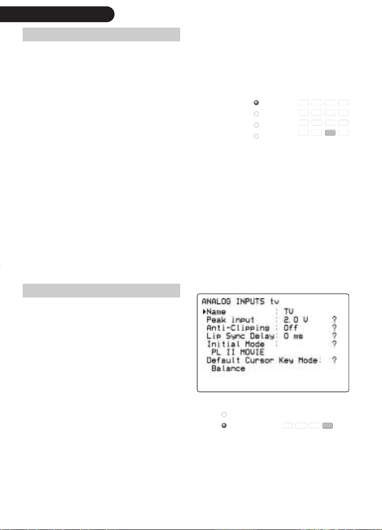
surround & initial modes
You can assign an Initial Mode to each
analog and digital audio input. This mode
will be applied to the source the first time
the source is selected after the AV192R is
switched on. The initial mode applied to
any given input will be ignored by the
AV192R if a digital data stream with
embedded control flags is detected.
time
–
subtitle
Additional decoding/post processing
modes currently available for a source can
be cycled through by repeatedly
surround
THX Cinema
surround
10 0 THX
audiotitle angleshift
pressing the THX button/key.
Initial modes, selected by the user for each input, using the change set-up menu (see page
52 / 53 for details) are dynamically changed whenever the user changes the mode
manually using the surround key/button, until the AV192R is switched off.

THX: transforming for use at home
Movie soundtracks are created to sound right in a cinema. The
soundtrack is mixed and tailored to allow for the specific
characteristics of cinemas and the equipment used in them. The
differences between the cinema and Home Cinema environments
mean that exact reproduction of the cinema soundtrack in a Home
Cinema provides a very different experience, typically with a very
‘bright’ sound. To correct for this and other differences, THX
specifies processes that are carried out on the soundtrack: Reequalization™, Timbre matching™ and Adaptive decorrelation™.
These processes are combined under the name THX Cinema.
THX Ultra2
Re-equalization™ is applied to all the
speaker signals, principally to
A lot has changed in Home Cinema
since the THX standards were initially
laid down. VHS tapes were joined by
laserdiscs and more recently by DVD,
soundtrack encoding has progressed
from analog Dolby Pro Logic through
the now ubiquitous Dolby Digital 5.1
to discrete 6.1, and music has gone
from being a solely 2-channel stereo
format to fully embrace multi-channel.
The advances in the THX specification
embodied in the new THX Ultra2,
available in the AV192R,
accommodate the changes that have
occurred and specify systems that can
perform superbly with both movies
and music, with a single speaker
layout that will suit all programme
material.
counteract the high frequency boost that
is applied to the movie soundtrack to
account for the high frequency losses of
the cinema environment.
Adaptive decorrelation™ acts on mono
surround signals to provide a more
spacious effect and allow the surround
effect to be properly heard over a
larger listening area. It is not applied if
the surround signals are stereo (i.e. if
left and right surround signals are
different).
Timbre matching™ is applied to the
surround speaker signals to match them
tonally to the front left/right and centre
speakers, preventing a change in the
tone of sounds as they pan around the
speakers.
THX post-processing
|
29
|
30
THX post-processing
introduction of back channels
A significant recent development has been the addition of the
surround back channel, which first appeared in cinema soundtracks
in 1999. THX have been at the forefront of this development,
working closely with Dolby Laboratories to produce THX Surround
EX. THX Surround EX encodes an additional channel within the left
and right surround channel signals, which is extracted by a Dolby 3
decoder. DTS-ES discrete takes this process a step further, with a
discretely encoded 6th channel.
THX recommend that the surround back
loudspeakers are placed quite close together,
facing towards the listener, although during
the setup of the AV192R you will be asked
whether the surround back speakers are
close together or apart (for details see page
59), and signal levels sent to the back
speakers will be adjusted accordingly to
achieve consistent results.
replay of 5.1 through 7.1 speakers
The addition of the surround back channel has prompted a rethink on the
processing front, with a view to making best use of the extra loudspeakers
with 5.1 material. THX Surround EX processing can be applied to any 5.1
source material to generate a signal for the back channel. This works well
for much 5.1 material, but gives poor results if the surround content of the
5.1 material is mono as this results in all of the surround information being
directed to the back speakers and none to the surrounds. To prevent this,
and improve results with all 5.1 source material, THX Cinema is replaced
by THX Ultra2, which employs THX Advanced Speaker Array processing to
optimise the surround experience.
THX boundary gain compensation
There have also been enhancements to bass management, with a new
optional ‘Boundary Compensation’ mode added to achieve better bass
integration when the listening positions are close to the back wall. Such
positioning results in low frequencies being boosted (by a process called
‘Boundary Gain’, in which the reflected sound from the wall adds to the
direct sound from the speaker increasing its level). Boundary Compensation
provides additional low frequency filtering on all channels to achieve a
more natural low frequency balance, for details see page 60.
THX Cinema, THX Ultra2, THX Music
THX Cinema
This processing mode includes processing includes the
re-equalization, timbre matching and adaptive
decorrelation of THX Cinema, as described on page
29. To apply THX Cinema post-processing, press the
THX key on the remote or the THX button on the front
panel, once or repeatedly until you selected your
desired mode.
THX Ultra2
This processing mode includes the re-equalization, timbre
matching and adaptive decorrelation of THX Cinema, but also
detects and compensates for monaural surround information,
feeding it directly to the back speakers but also feeding a
decorrelated form to the left and right surround channels. In
the case of 5.1 material with stereo surround information, the
surrounds are processed to pass the ambient information to
the left and right surrounds and the directional cues to the
surround backs. The overall result is to achieve an enhanced
surround experience over a wider listening area.
To apply THX Ultra2 post-processing, press the THX key on the
remote or the THX button on the front panel, once or
repeatedly until you selected your desired mode.
(1)
(1)
surround
THX Cinema
surround
10 0 THX
audiotitle angleshift
|
31
THX Music
This processing mode benefits 5.1 music recordings, as
it employs a modified form of the THX Advanced
Speaker Array processing. THX Ultra2 Music takes
account of the fact that music material is mixed and
monitored in a very different environment than film
soundtracks. In this mode the front left, right and centre
signals are passed directly to the loudspeaker outputs
without any re-equalization. The surround content is
timbre matched (again without re-equalization) and
(where required - i.e. mono surrounds) decorrelated
before being fed to the left and right surround
channels, whilst a processed version of the surround
information is sent to the surround backs to enhance
spaciousness and widen the listening area.
To apply THX Music post-processing, press the THX key on the remote or the THX button on
the front panel, once or repeatedly until you selected your desired mode.
1. THX ULTRA2 and THX Music are only available if your system setup includes back speaker(s).
Despite the name,
THX Ultra 2 Music is also
beneficial for film soundtracks
that have been specifically
mixed for the home
environment, as is the case for
many of the newer DVD
releases. Such soundtracks do
not require the re-equalisation
that is part of THX Ultra2
Cinema processing.

|
32
THX Surround EX
This mode can be used to process Dolby Digital Surround EX
encoded discs. THX Surround EX is a joint development of Dolby
Laboratories and the THX division of Lucasfilm Ltd. Movie
soundtracks that have been encoded with Dolby Digital Surround EX
technology are able to reproduce an extra channel which has been
added during the mixing of the program. This channel, called
Surround Back, places sounds behind the listener in addition to the
front left, front centre, front right, surround right, surround left and
subwoofer channels. This additional channel provides the
opportunity for more detailed imaging behind the listener and
brings more depth, spacious ambience and sound localisation than
ever before.
When released to the home consumer market, movies that were
created using the Dolby Digital Surround EX technology, may (but
some don’t!) have a note to that effect on the packaging. A list
of movies created using this technology can be found on the
Dolby web site at www.dolby.com.
You can also activate the THX SURROUND EX mode during the
playback of standard 5.1 channel material (i.e. movies not
including a Dolby Digital Surround EX encoded back channel).
In such a case the information delivered to the Surround Back
channel will be program dependent and may or may not be
pleasing depending on the particular soundtrack and the tastes
of the individual listener.
(1)
If your AV192R does not include all 7.1 channels then you will not
be able to extract the back channel information. You will not lose
information but the spatial distribution of the surround sound will not
provide the same depth and spacious ambience (as the sound,
intended for the back channel is equally replayed through the left
and right surround loudspeakers).
To apply THX SURROUND EX, press the THX key on the remote or
the THX Cinema button on the front panel, once or repeatedly until
you selected your desired mode. If the current surround mode for the
selected input does not support THX, the AV192R will select the
appropriate surround mode. Press either the THX key or button
again to turn off THX Cinema post-processing.
1. THX SURROUND EX is only available if your system setup includes back speaker(s).

surround modes: mono, direct, bypass, HDCD
The following decoding and surround modes are available
MONO
In this mode the AV192R combines the left and right channels of a stereo signal to produce
a mono signal. If the centre speaker is set to bass-limited, for details see page 58 / 61, or
the centre speaker isn’t connected, the AV192R will send sound to the left and right front
speaker (or the subwoofer if they are also set to bass-limited).
DIRECT
In this mode the AV192R works like a normal stereo audio pre-amplifier. It is only valid for
conventional stereo sources (e.g. analog inputs or a CD). No processing is applied to the
signal, which is sent only to the left and right front speakers. The programme source format
display will show L and R.
DIRECT + SUB
Works as DIRECT, but the left and right low-frequency signals will be directed to your
subwoofer. The signal, sent to the subwoofer will be ‘time aligned’, correcting for a potential
distance difference of the subwoofer from your listening position compared to the left and
right loudspeakers. If you do not have a subwoofer you cannot select this mode.
BYPASS
This is not strictly speaking a mode, but is listed here for completeness. BYPASS indicates the
use of the 5.1 BYPASS input, for details see page 9. The signal is bypassing the Digital
Signal Processors, hence are never converted to digital and is therefore the only available
mode for the 5.1 BYPASS input.
®
HDCD
This mode is available as an option, please refer to ‘How to enable an option’ on page 114
how to enable HDCD and other software options. All CD and DVD players with a digital
(2)
output
can reproduce HDCD. The increased resolution is generated inside the AV192R
using additional data on an HDCD encoded CD. HDCD cannot be selected as an Initial
Mode, it automatically replaces DIRECT if you have selected DIRECT and play an HDCDencoded CD.
(1)
:
|
33
HDCD + SUB
Works as HDCD, but the left and right low-frequency signals will be directed to your
subwoofer. The signal, sent to the subwoofer will be ‘time aligned', correcting for a potential
distance difference of the subwoofer from your listening position compared to the left and
right loudspeakers. If you do not have a subwoofer you cannot select this mode.
, HDCD®, High Definition Compatible Digital®and Pacific Microsonics™ are either registered
trademarks or trademarks of Pacific Microsonics, Inc. in the United States and/or other countries.
1. not all input signals will support all modes.
2. this assumes the player does not alter the digital data, stored on the CD.

|
34
surround modes: stereo, Pro Logic. Pro Logic II
STEREO Downmix
Down-mixes a digital multi-channel signal, e.g. Dolby Digital or DTS, to a two channel stereo signal
(front left and right) only.
PRO LOGIC
Applies Dolby Pro Logic decoding. This may be applied to any stereo source to give multi-channel
surround sound
surround information through the ‘normal' surround loudspeakers, the back channels or both. For
more details see page 64.
PRO LOGIC can be set to work with or without a subwoofer.
This is done in the Bass Redirection Rules found in the subwoofer configuration screen, see page 62.
PRO LOGIC IIx
Pro Logic IIx is a combination of Dolby’s acclaimed Pro Logic II processing and Dolby Digital
Surround EX, with a few extra wrinkles thrown in for best sound quality - be it 5.1, 6.1 or even 7.1.
Pro Logic II reduced the performance gap between Pro Logic and discrete Dolby Digital 5.1 by
creating five full-bandwidth output channels from 2-channel sources. Pro Logic IIx extends the already
highly sophisticated Pro Logic II algorithms to process native stereo and 5.1-channel content to
produce 6.1 or 7.1 output channels.
Pro Logic IIx modes are only available if your system setup includes back speaker(s), otherwise the
modes revert to Pro Logic II.
Pro Logic IIx processing can be applied to all two channel sources, plus Dolby Digital 5.1 and even
material encoded with Dolby Digital Surround EX.
Three modes are available: PRO LOGIC IIx MOVIE, PRO LOGIC IIx MUSIC and PRO LOGIC IIx GAME.
PRO LOGIC IIx MUSIC
This mode gives music a more three dimensional representation, providing more spaciousness and
transparency and generating 6.1 or 7.1 output from stereo or multi-channel material.
(1)
. If you have a ‘7.1’ system set-up, then you can optionally reproduce PRO LOGIC’s
When processing stereo material the mode appears as PLIIx MUSIC, with multi-channel material the
mode will be shown as, for example, DD5.1+PLIIx MUSIC. PL IIx MUSIC can be user configured to
suit your taste and listening environment, for details see page 67.
PRO LOGIC IIx MOVIE
This mode improves the sound quality, channel separation and steering of Stereo, Dolby Surround
and Dolby Pro Logic (or similar) matrix encoded movie soundtracks, and generates Surround Back
channel information from multi-channel Dolby Digital soundtracks.
When processing stereo material the mode appears as PLIIx MOVIE, with multi-channel material the
mode will be shown as, for example, DD5.1+PLIIx MOVIE. PLIIx MOVIE is optimised for movie and
television soundtracks and does not allow any user configuration.
PRO LOGIC IIx GAME
This is a special mode to allow those who use their Home Cinema systems to enjoy video games to
get an even better gaming experience. The Game mode is specially tuned to ensure that the full bass
impact from surround effects in a game are delivered to the subwoofer - explosions shake the room
like never before!
1. Some Dolby Digital-encoded discs contain control information to allow the AV192R to detect PRO LOGIC automatically. For more details,
see page 54.

surround modes: DTS Neo:6, TMS, party
DTS NEO:6
DTS NEO:6 is an advanced sound format, creating six full-band channels from
2-channel sources.
Two modes are available: DTS NEO:6 MOVIE & DTS NEO:6 MUSIC
NEO:6 MOVIE
This mode is designed to enhance PCM (stereo) movie soundtracks or TV broadcasts.
Please note NEO:6 MOVIE cannot be used with Dolby Digital 2.0 (stereo) encoded
movies, unlike PRO LOGIC IIx MOVIE.
NEO:6 MUSIC
This mode can be used with any PCM (stereo) music recording and produces a pseudo
7.1 mix output. This can result in a wider sound space and better imaging.
TAG MCLAREN SURROUND 7
This is an audiophile, fully dithered, high-quality multi-channel surround processing mode,
capable of processing even 24-bit / 96 kHz recordings with no artifacts.
TM SURROUND 7 creates a 7 channel surround impression from mono or stereo music
recordings. Left and right channel remain unchanged compared to the original recording,
while the centre channel increases the stability of the front sound stage and the surround and
back channel supplement the ambience of the original recording.
If your system doesn’t include back channels, then the surround format reverts to
TM SURROUND 5.
|
35
TAG MCLAREN SURROUND can be set to work with or without a subwoofer.
This is done in the Bass Redirection Rules found in the subwoofer configuration screen,
see page 62.
PARTY SURROUND
This mode is, as the name indicates, designed to immerse a room in sound. It works with two
channel sources, such as analog and CD (PCM) stereo. Left and right front channel are
unchanged, the centre is used to provide better stability of the front stage (it uses TM Surround),
whilst the surround left (right) and the surround back speaker mirror the signal of the left (right)
front speaker. If you have a subwoofer, it will be automatically used.
Centre, surround and back speakers can be individually trimmed by up to +/- 10dB (for
details see page 60), allowing you to customise your party. Let's dance...

|
36
surround modes: Dolby Digital, DTS
DOLBY DIGITAL
This mode is automatically selected when a Dolby Digital-encoded disc is played.
MPEG-2
This mode is available as an option, please refer to ‘installing a software option’ on page 114.
This mode is automatically selected when an MPEG-2- encoded disc is played.
DOLBY DIGITAL EX
DOLBY DIGITAL EX is only available if your system setup includes back speaker(s)
Home cinema uses many different surround decoding formats. THX SURROUND EX activates,
see above, both the matrix decoder for the back channels (‘EX’) and THX post processing.
However, some Dolby EX encoded DVDs are already optimized for the use at home, meaning
they do not need THX post processing again. In this instance you should use DOLBY DIGITAL EX.
DTS
This mode is automatically selected when a DTS-encoded disc is played.
DTS MUSIC
Modern movies recorded in DTS require the DTS mode, described in the paragraph above, for
accurate replay. DTS MUSIC is required for backwards compatibility for some older DTS discs
and most DTS music CDs, where a 10dB reduction in the LFE channel is required.
DTS-ES 6.1 MATRIX
DTS-ES 6.1 MATRIX is only available if your system setup includes back speaker(s)
DTS-ES 6.1 Matrix includes a back surround signal, matrix encoded into the left and right
surround channels, on specially encoded DVD movie releases.
If your setup does not include all ‘7.1’ channels then you will not be able to extract the back
channel information. You will not miss anything except the spatial distribution of the surround
sound will not provide the same depth and spacious ambience.
DTS-ES 6.1 DISCRETE
DTS-ES 6.1 DISCRETE is only available if your system setup includes back speaker(s)
DTS-ES 6.1 DISCRETE provides the back channel information as a discrete, i.e. independently
stored signal. The advantages are increased headroom and clarity of the back channel.

surround modes: DTS 96 / 24, Multi-channel variations
DTS 96/24
This new format allows recording of up to 5.1- channels with up to 96 kHz/24 bits on
ordinary DVDs. Previously 96/24 has only been available on DVD as two channel PCM
(which the AV192R can also process using the format Direct, described on page 33). DTS
96/24 exclusively delivers 5.1 channels in 96/24 along with full-motion video, for feature
film soundtracks and music programs on DVD-Video. The AV192R will automatically detect
DTS 96/24 recordings and engage its advanced DTS 96/24 processing- indicated by the
DTS 96/24 LED, located at the AV192R’s front fascia.
MULTI-CHANNEL
This is not strictly speaking a mode, but is listed here for completeness.
Multi-channel recordings can include a different number of channels: from two to six
channels plus a subwoofer. Unfortunately some 6.1 multi-channel recordings do not contain
the necessary control information to allow the AV192R to detect their correct recording
format. MULTI-CHANNEL is used in the setting of the Initial Mode for digital audio sources,
for details see page 52 / 53, to allow an easy way of entering a mode which will select in
most instances the best solution for multi-channel recordings:
This Initial Mode will automatically engage:
• Multi-channel decoding of Dolby Digital or DTS sources
•- Dolby Pro Logic II Movie for two channel sources
• Multi-channel + THX Surround EX, if a recording is detected including the THX Surround
EX control flag for automatic selection
|
37
• DTS-ES 6.1 Matrix if a DTS recording is detected, including the DTS-ES 6.1 Matrix
control flag for automatic selection
• DTS-ES 6.1 Discrete, if a DTS recording is detected, including the DTS-ES 6.1 Discrete
control flag for automatic selection
MULTI-CHANNEL+THX
MULTI+THX ULTRA2
MULTI-CH.+THX MUSIC
MULTI+THXSurEX ON
MULTI-CH.+MATRIX
These modes behave like MULTI-CHANNEL, but apply also THX Cinema, THX Ultra2, THX
Music, THX Surround EX. The + MATRIX mode selects PL IIx Movie for Dolby Digital material
or ES Matrix for DTS material.

|
38
height channel
HEIGHT CHANNEL
Movies mixed with height channel information and many mixed in
THX Surround EX (Dolby EX) or DTS-ES 6.1 can benefit from the
height channel processing, which will ensure that sound intended to
fly over you, will no longer fly through you.
Movies recorded with height channel sound cannot be automatically
detected as they do not contain a control flag which could allow an
av processor automatic engagement of the height channel decoder.
Engagement of the height channel decoder can be defined
for each digital audio input separately using the When To
Use Height Spkr property in the additional setting menu,
for more details see page 55.
Please see page 13 regards connecting the height channel
to your AV192R.

programme source format display / tuning the LFE or subwoofer level
programme source format display and audio status
The programme source format display area of the front panel
display indicates which output channels are available at any time.
You can also press shift + surround and the
audio status screen comes up- in the
example receiving two channel Dolby
Digital data stream processed into 5
channels, using Pro Logic II Movie.
tuning the LFE or subwoofer level
The LFE (Low-Frequency Effects) channel
(1)
level
, such as Dolby Digital 5.1 or DTS 5.1,
can be reduced by up to 10dB if you feel
that the bass is too loud for your
listening/viewing room.
|
39
In contrast, if you use a surround mode
which supports a subwoofer (but does offer a
dedicated LFE channel) such as Direct + Sub,
then you can both increase and decrease the
subwoofer level by up to 10dB.
To adjust the level press the LFE – or LFE + keys on the remote. The
applied setting will be shown in the status screen, as explained on
page 23 and shown in the example screen, above.
restoring the base setting
The LFE/subwoofer adjustment (including all temporary corrections,
including lip sync delay and entre gain applied under Quick
Settings, see page 40 and balance settings, see page 27) will be
restored by pressing the normal ok / normal button on the front
panel or the normal key on the remote.
1. The LFE channel is the 0.1 channel in a 7.1 / 5.1 recording, including very low frequency (bass) sound effects.
analog +
station +
return
skip
+
dig ---dig +
e
w
---
skip
cancel
station ---
functions
record
LFE
pause
+
analog ---
store
f
ok
f
play
d
erase
---
stop
LFE
eject
image
r
normalok

---
---
|
40
cursor key assignment
selecting a cursor assignment
analog +
dig
station +
return
skip
skip
cancel
station
pause
+
r
ok
---
e
play
w
---
stop
---
analog ---
The cursor keys G, H, E and F plus the skip + and skip - keys
have different features assigned to them, depending on the mode
your AV192R is currently in.
The AV192R will automatically switch between these assignments,
anticipating what your most likely expectation will be at any moment.
You can also switch manually between these assignment at any time. Just keep the ok key
pressed for more than three seconds and a screen similar to the one shown on the left comes up.
The position of the cursor E indicates the
currently selected cursor key assignment,
Balance in the example screen above. If
you want to select another assignment,
simply select it
cursor key, followed by ok. The screen will
disappear
(1)
pressing the G or H
(2)
with the cursor key assigned to
your choice:
1 balance
functions
record
LFE
+
store
f
dig +
f
d
erase
---
LFE
eject
image
This feature is described on page 27.
2 Pro Logic II parameters
This feature is described on page 67.
3 internal radio tuning
This feature will work if your AV192R
includes the optional FM and/or DAB
digital radio. It allows you to switch
between stations, stations stored in memory
or scan the frequency in 50kHz steps (FM
only). For more details, see page 79.
4 T32R radio tuning
As Internal Radio Tuning but applied to the T32R radio, if connected to the AV192R via
TAGtronic Bus. For more details, see page 112.
1. the cursor assignment will only control its associated function if it is available at that time.
2. the display will also switch off after approximately 10 seconds if no selection is made.

5 quick settings
Quick Settings modify the lip sync delay
(for an explanation see page 51), the
centre speaker gain (for details see page
60) and switch the night mode on/off (see
page 45). Changes made under this cursor
assignment are temporarily applied for the
current input only, i.e. they will be
deactivated when you change the input or
put the AV192R into standby.
RS232/IR TX controller macros
If your AV192R is equipped with the
optional RS232/IR TX Controller then you
will find a sixth entry which allows you to
assign macros to the cursor and skip +/
skip - keys for each input key (tv, vcr… dab
and tape). For more details see page 104.
VSM2048 Video Scaler
If your AV192R is equipped with the
optional VSM2048 Video Scaler then you
will find an entry for Video Processing. This
allows you to change the screen fit mode,
the aspect ratio of the current video input
(used by VSM2048 to format the image to
suit your display) and to turn the Picture-InPicture window on and off.
cursor key assignment
|
41
cursor movement inside the set-up menu
If the AV192R’s set-up menu (or any on screen text expecting cursor key operation) is
activated, the cursor keys will work as up, down, left and right.
changing a cursor assignment using the front display only
The cursor assignments can also be changed using the AV192R’s front display only. Press ok
for more than three seconds and the front display (if switched on) will show one of the
following possible assignments: BALANCE, PL II, AV RADIO, T32R, QUICKSET, RS232 or
VIDEO. You can switch between different assignments using the cursor G or H keys. Press
ok to confirm your change.

|
42
the AV192R set-up menu: introduction
Previous chapters described the connection of the AV192R with other components of your
system and explained how to operate your AV192R, once being set-up. The following
chapters will explain how you configure the AV192R for best performance - without this, your
AV192R will not operate to its full potential
the AV192R set-up menu
The AV192R uses a series of on-screen menus to enable you to set-up and customize the
settings to suit your home cinema system . You must have your display connected to an
output providing OSD, for details see page 19.
Please press the menu key and the following screen will come up
Choose a desired option using the G or H
keys and press ok to select.
Online help is given by moving the cursor
to the ?, using E, followed by ok.
You may exit the AV192R’s setup menu at
any time by pressing the menu key again this will save all changes you have made
up to this point
You may alter parameters at any time.
Changes will be retained when the unit is
switched off or even if the mains power
lead is removed.
(1)
:
The following options are found on the Welcome screen
video Background
You may choose to overlay any menu text on the picture you are watching (if you are
watching one), or to temporarily disable the picture so that any on-screen menu shows on a
plain dark grey background.
First-Time Set-up Wizard
The set-up process will be simplified if you are new to the AV192R if you run the First Time
Set-up Wizard, as this will ensure you enter all the essential parameters required for optimal
performance. Details are given on page 44.
1. The AV192R operating software is upgradable, so future versions may look and operate slightly differently to the way described in
this manual.

the AV192R set-up menu: introduction
Change Set-up
This menu allows you to select each parameter from a list and to tune/modify it individually.
We will explain all options in detail, please refer to page 45.
Select Help - Remote Control Keys
A short summary of features assigned to
specific keys or key combinations.
|
43
AV Options + Status
Select this menu if you want to know
everything about the configuration of your
AV192R, i.e. its hardware and software
configuration and the processing status.
This menu allows you also to activate a
Software Option using an Option Code,
for details how to enable a software
option, refer to page 114.

|
44
First-Time Set-up Wizard
The First Time Set-up Wizard takes you through the set-up process step-by-step in the correct
sequence.
You will see a series of text screens offering help in how to use the Wizard. Press ok after each
one. This will lead to the screen shown.
You will need a tape measure and,
ideally, a sound level meter for
best results
Essential
If you have not set up the AV192R
to match your loudspeakers, you
should choose - Part 1: Essential.
It is important that you perform this
set-up operation in order to
optimize the performance of your
entire home cinema system.
Convenience
Selecting - Part 2: Convenience -
will help you customize your
AV192R to your specific needs.
You can return to either part of the
set-up at any time.
Change Set-up
There are special functions and
features, required for advanced
configurations. These are covered
in the Change Set-Up menu,
described next.

Change Set-up: DD / DTS Night Mode
Change Set-up menu
The Change Set-up menu splits in
many powerful sub menus, which
will be described in detail below.
The screens available to you might
differ from those shown in this
manual, if your AV192R has not all
hardware and software options
installed. It might also differ if the
the software version, loaded into the
AV192R is different to the version
used when writing this manual.
DD/DTS night mode
The AV192R incorporates a Night Mode, which reduces the dynamic range for quieter
listening, so that you can comfortably hear quieter passages at lower volume levels. The loud
elements (such as violent explosions) become slightly quieter and the quiet elements (such as
soft speech) become slightly louder.
Night Mode only works with Dolby Digital or DTS Digital Surround sources including
Night Mode control parameters.
|
45
To select Night Mode within the Change Set-up sub-menu from the main menu, and use the
G or H keys to toggle from Off to On. Night Mode will remain selected until it is specifically
switched off.
When the Night Mode is active, i.e. a DD or DTS DVD with the necessary night mode
parameters is replayed, the volume display will change from VOL on the front panel display
to NIGHT. The volume display on the on screen display will also change to night when Night
Mode is active.
You can also switch Night Mode On or Off using the skip + or skip - keys if the cursor keys
have been assigned to quick settings, as described on page 40.

|
46
Displays > front panel text configuration
front panel configuration
The Displays menu allow you to
configure the front panel and the on
screen display.
This submenu
defines the
layout of the
front panel
display to your
preferences.
front panel text
This menu allow you to define the exact information you would like to see on the front panel
display under normal operation and when in standby.
child lock
Set Child Lock to On if you want to deactivate all control buttons (including the volume knob),
located at the AV192R’s front panel. Please don’t lose the remote control, as it offers the only
way to de-activate this feature, once engaged. The power on/off button will still work, even
if Child Lock is engaged, as this button is not under software control.
clock display during standby
During standby you can display the time and the date - if you wish.
Pre-Amp versus Cinema mode
The volume level can be shown in reference to the Dolby Reference Level or from 0 to 99 like
a pre-amplifier- for more details see page 25.
startup message
Here you can enter a personalised message, which will appear on the front panel display for
a few seconds each time you turn on your AV192R. If you do not wish to set a personal
message, delete any entry, should one already exist.

Displays > front panel brightness
This submenu
specifies the
brightness
(1)
of the
display and the LEDs
on the AV19R’s front
fascia
brightness levels
The brightness associated with High Level, Medium Level and Low Level can be user
configured, selectable from 1 (dark) to 10 (very bright).
The brightness applied when the AV192R is in standby, assuming the clock is configured to
display, is the Standby Level, which is selectable from 1 (dark) to 7 (bright).
startup brightness
This is the brightness the AV192R front panel display will switch to after the AV192R is
powering up.
reducing display brightness after a while
(1)
|
47
The display can be configured to switch to the After Hold Brightness level after a Hold Time
of 1, 2, 3, 5, 10, 20, 30 or 60 seconds. The display will switch automatically switch back to
the brightness level it came from, if the display content changes. Set Hold Time to Keep On if
you want the display remain on all the time during operation. Set the After Hold Brightness to
Off, if you want the display to switch off.
switching the blue power/standby LED off
If the front display is switched off, the blue power/standby LED can also be switched off by
setting the Blue LED State when display Off to Off. This prevents any unwanted light from
interfering with your display device.
If you have other TAG McLaren products connected to the AV192R via the TAGtronic Bus
and you have configured the AV192R to transmit its brightness level via the TAGtronic Bus to
other units -for details see page 109 - then they will synchronise their display brightness
including the blue power LED brightness to the AV192R.
1. The front display of the AV192R is a so-called ‘Vacuum Fluorescent Display’ (VFD), a technology known for excellent readability and
brightness. The average life of a VFD is well over 10 years, requiring no maintenance. However, a VFD will slowly reduce its maximum
brightness over time, but only those segments which are illuminated will become darker over time. So if you show the same information
at high brightness for any prolonged period, e.g. VOL -30.0, then only those segments making up this information will darken, whilst all
others will remain unchanged. As a result if you show any other information, consisting of dark (=aged) and bright (=unaged) segments,
an uneven brightness will be visible. Aging can be reduced by configuring the display to switch off after a few seconds, as described
above.

|
48
Displays > on-screen display & radio text
on screen display
configuration
This sub menu configures the On
Screen Display, including its
default video format, required for
generating OSD when no video
source is selected/connected
If your AV192R includes
the optional PSM192
then you can
activate/deactivate
OSD independently for
Composite/Video and
RGB/YPbPr sources.
radiotext display
1. Radiotext can only be superimposed if your setup allows for on screen display, for more details see page18 / 19.
(1)
This is one of 3 very similar
screens, available for the T32R (if
connected via the TAGtronic Bus),
the AV192R’s internal FM and the
DAB digital radio, if available.
It allows the scrolling radiotext, if
one is received, to be displayed
on the front panel and/or
superimposed to the video signal.
The latter can be restricted to the
instance when listening to the
radio only or when on any input.

video inputs
changing a name of a video input
Select the name you wish to alter, and the
first character will flash, indicating the
cursor position. The cursor position may be
changed using the F or E keys. The
character may be changed using the G or
H keys or entered directly using the
alphanumeric keypad. These are multifunction keys and may require up to five
presses to enter the correct character. For
example, pressing the 2 key once will
change the character under the cursor to
an ‘a’. Further key presses will cause the
character to cycle through the sequence
‘b’, ‘c’, ‘2’, and return to ‘a’. Pressing the
shift key toggles between lower and upper
case. The edited name may saved by
pressing the ok key.
Input Options > video inputs
This submenu allows the configuration of all
video inputs
The video inputs can be renamed to a
name of your choice- the screen for the
Composite inputs is shown as an example.
Video outputs are explained on page 18.
The RGB/YPbPr/HDTV option exists only, if
the RGB/Component Switcher option is
installed.
|
49
suppressing video inputs
If you erase a name of a currently unused video (analog /digital) input, i.e. by over- writing
all characters using the space key, then this input will be skipped when scrolling through
inputs using the analog, digital or video keys. As soon as an input is renamed it will
reappear in the appropriate list.

|
50
Input Options > RGB input format / DVI & HDMI inputs
RGB input signal configuration
For the correct operation of the
optional Progressive Scan Module
PSM192, for details see page 68,
it is essential that you configure the
input video format of the three
RGB/Component inputs.
Options for RGB1, RGB2 and RGB3
are: YPbPr Component, RGB with
Sync on Green, RGB + separate
Composite Sync.
Options of the HDTV input are: PC
RGB + Separate HV, HDTV YPbPr
Component, HDTV RGB +
Composite Sync.
See your video source’s handbook
for details.
DVI / HDMI input switcher
The next sub menu will deal with
the DVI/HDMI Switcher when
this option becomes available.

Input Options > analog audio inputs
|
analog audio inputs
Selecting Analog Audio Inputs will bring up
the list of all available analog stereo inputs.
Select the input you would like to
configure using the G or H keys,
followed by ok, and the following
screen comes up, allowing you to
modify these parameters:
name change
The analog inputs can be renamed to a name
of your choice - just follow the instructions
described under video inputs on page 49.
peak input
You can calibrate the input sensitivity by entering a voltage here. The higher the value the lower
the sensitivity. A value should be selected that results in an equal volume level for all your
analog inputs without overloading the input. You can let the AV192R let the input calibrate for
you, as described on the next page.
51
anti clipping
This feature enables/disables the input Anti-Clipping operation of the AV192R. When this
feature is On, the AV192R will automatically increase the peak input level of any analog
input which clips, i.e. is too large and will cause distortion.
lip sync delay
A film’s audio track may not be perfectly synchronised with the picture , i.e. the dialogue
consistently fails to match the movement of the speaker’s lips. This can have two major causes:
1... poor recording- which might often even be varying during a movie
2... video processing takes longer than audio processing, caused by de-interlacing and
scaling technology
Use the Lip Sync Delay, as described in this menu, for correction of permanent delay, as
required for a video processor. Use the temporary Lip Sync Trim, as described on page 40
for any additional correction required for a specific programme/DVD.
1. Occasionally you will find there are lip-sync problems, even with ‘correctly’ synchronised soundtracks. This may be because of poor
dubbing (matching the dialogue when the audio track is re-recorded) if the film has been dubbed from another language. It is not
possible to correct bad dubbing as the delay is constantly changing
(1)

|
52
Input Options > analog audio inputs
initial mode
The AV192R offers a huge number of different processing modes, described in chapter
‘surround modes’ on page 28. This feature allows you to specify which surround mode you
like the AV192R to engage when you select an input source associated with the analog audio
input, in our example TV.
default cursor key mode
The functionality assigned to the cursor keys F, E ,G and H and the skip + and skip - keys
can be user configured, for details see page 40. You can set a cursor assignment to be
automatically recalled when you select an analog audio input.
calibrate input sensitivity
You can calibrate the analog input sensitivity by entering a peak input voltage, as shown on
page 51.
Select Calibrate Sensitivity ...? to let the
AV192R automatically detect the
appropriate sensitivity for you.
Select an analog input to set-up by using
the analog input selection button on the
front fascia or use the shift + G or shift +
H keys of the remote. You can also use the
source selection key, assigned to the
analog input you like to change. The
selected input is shown in the top left of the
screen, next to the word ‘Source =’ - in the
example above SAT.
Play some programme material on that input that contains a loud passage, then select Auto
Set for convenience and press ok. The AV192R does everything for you- the process will
take 20 seconds to complete.
Alternatively set the sensitivity manually: Play some programme material on that input that
contains a loud passage, then select Manual Set and press ok. The current sensitivity level
starts flashing. Set the sensitivity using the on-screen level meter
decrease the sensitivity and the E key to increase it
meter within the marked area (double arrows on the on-screen display or chequered area
on the front panel display). Press the ok key when you happy with the setting. If the word
‘OVER’ (which indicates an overload) appears between the double arrows (and on the
front panel display), make the input less sensitive (a higher number) using the F key.
1. The on-screen level meter is represented by the bars which flash on the ‘L’ and ‘R ’ lines. They indicate the peak sound level of the source.
2. You may enter a figure directly by using the keypad. This figure refers to the peak input level and is measured in volts.
(2)
. The correct setting should keep the
(1)
. Use the F key to

Input Options > digital audio inputs
digital audio inputs
Select the input you would like to
configure using the G or H keys,
followed by ok, and the following
screen comes up, allowing you to
modify these parameters:
name change
The analog inputs can be renamed to a name
of your choice - just follow the instructions
described under video inputs on page 49.
initial modes
The AV192R offers a huge number of different processing modes, described in chapter
‘surround modes’ on page 28. This feature allows you to specify which surround mode you
like the AV192R to engage when you select an input source associated with the digital audio
input, in our example DVD. You can select a different Initial Surround Mode depending on
the sampling frequency of the digital recording. CD’s use 44kHz, DVDs typically 48kHz and
some high resolution 2 channel DVD/PCM recordings use 96kHz.
|
53
DTS mode
DTS exist in two versions: DTS and DTS Music. Recent movies recorded in DTS require the DTS
mode for accurate replay. DTS Music is required for backwards compatibility for some older
DTS discs and most DTS music CD’s, where a 10dB reduction in the LFE (Low Frequency
Effects) channel is required
connected to your CD player, assuming you have Music CDs recorded in DTS.
(1)
. We recommend to set all inputs to DTS, except the input
DTS delay
DTS-encoded CDs (not DVD!) may be played on normal CD players with digital audio outputs.
On conventional systems, this would be heard as a loud, continuous noise, since DTS-encoded
discs require special decoding. The AV192R will automatically detect this and will decode the
CD in DTS mode. You can set the AV192R to mute while auto sensing in order to prevent the
very short burst of white noise on your front loudspeakers. You may find that with DTS Delay:
On you miss a very short section (fractions of a second) of normal music CD's. We recommend
that you only enable DTS Delay for sources that will have DTS Digital Surround- encoded discs
played on them.
1. this will mean that very low bass, if recorded in the LFE (0.1) channel will be replayed at about half the volume than using DTS.

|
54
Input Options > digital audio inputs
lip sync delay
Use this Lip Sync Delay, as described in more details on page 51, for correction of permanent
delay, as required for a video processor. Use the quick setting, as described on page 40 for
any additional correction required for a specific programme/DVD.
Sync ‘T2L’ Link
The TAGtronic Sync Link improves sound quality of products featuring this advanced
technology. Connect the TAGtronic Sync Link, as described on page 10 - then activate the
Link by setting Sync ‘T2L’ Link: On.
how to confirm that the TAGtronic Sync Link T2L is working
The name of a digital input with enabled Sync ‘T2L’ Link will be shown with the extension e.g. DVD-T2L, indicating that the TAG Sync Link has been successfully established and is working.
Should the Sync ‘T2L’ Link fail, an error message ‘no TAG Sync Link’ will be displayed.
Selecting Additional Settings... will bring up two additional features:
default cursor key mode
The functionality assigned to the cursor
keys F, E ,G and H and the skip + and
skip - keys can be user configured, for
details see page 40. You can set a cursor
assignment to be automatically recalled
when you select an analog audio input.
T2L,
use PL/PL II with DD2
Dolby Digital exists also as two-channel recordings, called Dolby Digital 2.0. These DD2
recordings can include a left/right front channel or left/right front plus surround information matrix encoded using Dolby Surround. Dolby Digital DD2 includes the ability to set an
indicator (a flag), allowing the AV192R to automatically detect if surround information is
present or not, but unfortunately it has been found that many DVD authors and digital
satellite broadcasters flag their programmes incorrectly.
The feature use Pro Logic/Pro Logic II with Dolby Digital 2.0 recordings has been introduced
to overcome this by overwriting the ‘transmitted’ flag with your choice. Select If Pro Logic
Encoded if you want to follow the flag included in the programme material, select Always if
you want Pro Logic processing always engaged and Never if you always want Pro Logic
processing disabled.

Input Options > digital audio inputs
height channel configuration
Movies mixed with height channel information, such as the re-release
of ‘We Were Soldiers’ as well as many movies mixed in THX
Surround EX (Dolby EX) or DTS-ES 6.1 will benefit from the height
channel processing, which will ensure that sound intended to fly
over you, will no longer fly through you.
Movies recorded with height channel sound, cannot be automatically
detected as they do not contain a control flag which could allow an
av processor automatic engagement of the height channel decoder.
Set When To Use Height Spkr to if EX/ES flagged, if you want the
AV192R to engage the height channel decoder whenever you play
a DVD recorded in Dolby EX or DTS-ES 6.1, assuming the
recordings include the appropriate control flags - which is
unfortunately rarely the case for Dolby EX recordings.
Set
When To Use Height Spkr to if Matrix/THX Surr. EX Is Active, if you
want the AV19R to engage the height channel decoder whenever
you engage
Set When To Use Height Spkr to Manual Selection, if you want the height
channel processing to toggle between on and off, when pressing the
shift key, followed by 0. Height channel processing will be off, when
you change inputs or start-up the AV192R.
+ Matrix or THX Surround EX post processing.
|
55
Processing EX flagged material
Discs which are flagged as being EX encoded may have their
surround back channel information extracted using THX
SURROUND EX or DOLBY DIGITAL EX. This setting specifies which
method to use by default, the surround and thx keys may be used to
modify the choice when playing a disc. The setting also allows
selection of Override EX Mode, this is offered because some discs
are incorrectly flagged as being EX encoded when they are not. If
this option is selected it will be necessary to manually select DOLBY
DIGITAL EX or THX SURROUND EX decoding when a suitable disc
is played.

|
56
Input Options > 5.1 bypass
5.1 bypass
You can configure the 5.1 Bypass as
5.1 Bypass or as 3X Stereo.
Configured as 3X
Stereo the LEFT/RIGHT,
CENTRE/SUB and the S
/S Lwill form a
R
stereo pair.
You can enter the name
of your choice for the
5.1 Bypass or the 3X
Stereo pairs.
Signals connected to the 5.1 BYPASS will never be digitised- the only processing done to
them is analog volume control. Level calibration of your loudspeakers, for details see page
63 will be applied, catering for different loudspeaker and amplifier sensitivity
(1)
.
Bypass Output Trims...
If your DVD Audio or SACD player
does not output equal volume
levels for each channel, then you
can adjust that difference using
the 5.1 Bypass Output Trims. These
trims are superimposed to the
loudspeaker/amplifier calibration
and your overall volume setting.
1. Signals connected to the 5.1 BYPASS are not digitised, i.e. no processing, including the necessary time delay for different speaker
distances can be applied. Time delay must be defined within your source, i.e. the DVD Audio or SACD player.

Input Options > key assignments on remote
Each of these source
selection keys can carry
two audio inputs, audio1
and audio2, as some
sources offer different
output formats, e.g. a
DVD-Audio player offers
a digital SPDIF output,
when playing CDs and
DVD-Video discs, but
offers 5.1 analog when
playing DVD-Audio discs.
Key Assignment On Remote
The AV192R remote has
11 source selection keys,
labelled tv, vcr, sat, tuner,
aux, cd, ld, dvd, md, dab
and tape1, to which you
can in this submenu freely
assign the associated
audio and video inputs.
Selecting Key Assignment
On Remote brings up a
selection list of all source
selection key. Select the
one you want to edit and
a screen, like to next one,
come up:
|
57
audio1 and audio2 are the physical audio inputs that will be selected
when the corresponding source selection key is pressed. If both audio
inputs are assigned the source selection key will toggle between them
when pressed. Select Not Assigned for audio2 if you only want to assign
a single input to an input selection key.
Video is the physical video input that will be selected when the
corresponding source selection key is pressed. Select Don’t Change if
you want the AV192R not to change the currently selected video input,
e.g when switching to tuner.

|
58
Output / Speaker > loudspeaker definition / calibration
The OUTPUT/SPEAKER OPTIONS menu
includes everything to do with outputs, be it
audio or video.
loudspeakers
The first menu defines what
loudspeaker type you are using at
all possible 8 positions; the
second part will calibrate them
for best performance. Let’s start
with the Left/Right front
loudspeakers.
loudspeaker type
The AV192R need to know which
loudspeakers are present in your system and
whether they can reproduce deep bass
frequencies. In general, large loudspeakers
will be able to handle low frequencies and
small ones may not be able to. Select Full
Range for speakers which can also handle
deep bass, select Bass Limited if they cannot.
If no speaker is connected select None.
Bass Cutoff
The AV192R will re-direct low frequency signals Bass Limited loudspeakers cannot handle to
full range / subwoofer loudspeakers. You need to set the Bass Cutoff filter frequency between
40Hz and 150Hz at which this happens according to the bass handling capabilities of your
Bass Limited loudspeakers. Refer to your loudspeaker manual for this information - THX
certified speakers are Bass Limited, requiring a Bass Cutoff frequency of 80Hz THX.
The Bass Cutoff frequency can be set differently for Left/Right, Centre, Surround and
Surround Back loudspeakers, allowing you to unwrap the full potential of each loudspeaker.
Even if your left / right front loudspeakers are set to Full Range, you should set a Bass
Cutoff frequency, as this will define how surround modes, such as Direct+Sub split the
frequency band between main speakers and subwoofer.

Output/Speaker > loudspeaker definition / calibration
loudspeaker distance
The AV192R needs to know the distance of your loudspeakers from
your ideal seating position. These measurements are used to correct
for the time delays (of the sound reaching your ears) caused by the
difference in the distance between each loudspeaker and your
listening position. Enter the relevant figures by using the numeric key
pad (e.g. press 3 then 0 for 3.0m) or use the G or H keys.
loudspeaker level
The loudspeaker calibration level is very important to achieving a
correctly centred sound image, it should be carried out carefully.
Use the speaker Calibration menu, described on page 62 for your
initial set-up.
Perform above for all loudspeaker in your system.
The following descriptions cover items which are
different to the LEFT/RIGHT LOUDSPEAKER screen
|
59

|
60
Output/Speaker > loudspeaker definition / calibration
mode dependent speaker trims
The AV192R allows you to modify
the volume level for the Centre,
surround and Surround back
speakers
surround processing selected.
The setting for TMS (Pro Logic) will
also be used for TMS + Sub (Pro
Logic + Sub)
(1)
, dependent on the
distance between back speakers
There can be none, one or two
back speakers, being either Full
Range or Bass Limited.
If two back speakers are used, then
the AV192R need to know the
space they are apart. This will
allow the THX Advanced Speaker
Array technology to optimise the
algorithm when using THX Ultra2
post processing.
You can only use one back speaker output (SURR. BACK RIGHT) if you want to
engage the height channel. You can still use 2 back speakers but they both need
to connect, via suitable power amplifiers, to SURR. BACK RIGHT For more details
see page 38.
1. including the height channel, if activated

loudspeakers > subwoofer type / THX boundary control
Subwoofer type
The AV192R need to know the
type of subwoofer you are using in
order to apply the correct
processing.
Select THX Ultra2, if you have a
THX Ultra2 certified subwoofer or
one which can produce low
frequencies down to 20 Hz. Select
Normal if you use any other
subwoofer, None if you have no
subwoofer in your system.
LFE Cut-Off frequency
This parameter should not be confused with Bass Cut-off frequency
applied to all speakers. It describes the filter applied to the LFE (0.1)
channel. If you use a THX certified subwoofer you should set the
filter to 80 Hz THX. For subwoofers with an inbuilt cut-off frequency
it might be better to use None.
The LFE Cut-Off frequency also needs to be set if you don't have a
subwoofer as it defines how the LFE (0.1) signal is mixed into your
full range speakers.
|
61
THX Boundary Gain Compensation
If your subwoofer is THX Ultra2 certified or goes down to 20Hz,
then you can enable THX Boundary Gain Compensation, which
results in better bass integration when the listening positions are
close to the back wall. Such positioning results in low frequencies
being boosted by a process called Boundary Gain, in which the
reflected sound from the wall adds to the direct sound from the
speaker increasing its level. THX Boundary Gain Compensation
provides additional low frequency filtering on all channels to
achieve a more natural low frequency balance.

|
62
loudspeakers > subwoofer > bass redirection rules
subwoofer - bass redirection
There is an important additional
set-up menu within the
SUBWOOFER menu, the BASS
REDIRECTION RULES, which define
the use of the subwoofer with those
processing modes which do not
have a LFE (0.1) effect channel.
If LR=Bass Ltd
If your left and right front speakers
are bass- limited and you would like
your subwoofer, if available, to take
the bass frequencies your left/right
speakers, cannot reproduce, set the
processing mode you like to
configure to If LR=Bass Ltd. The Bass
Cutoff frequency is the frequency
defined in LOUDSPEAKERS then
Left/Right menu.
Always
If you want for a given processing
mode to combine your full range
left/right front speakers, then set
the rule to Always. This will treat
the full range speaker like a bass
limited speaker, transferring bass
energy below the Bass Cutoff
frequency, defined in
LOUDSPEAKERS> Left/Right, to the
subwoofer.
Never
If you want for a given processing
mode to ignore your subwoofer,
although your left/right front
speakers, are set to be bass
limited, then select Never.

loudspeakers > speaker calibration / alternative listening position
speaker calibration
The loudspeaker calibration procedure is
very important to achieving a correctly
centred sound image, it should be carried
out carefully.
We recommend that you use a sound
level meter (SPL) when performing this
part of the set-up as it is difficult to
judge the levels accurately by ear. Set
the SPL meter to ‘C’ weighting with
‘slow’ response and to read 75 dB SPL
at the centre of its scale. During the
calibration you should place the SPL
meter at ear level (with the microphone
pointing towards the ceiling) at your
preferred listening.
During the calibration the AV192R will send the THX-specified pink noise test signal to the
selected loudspeaker so that the output level from each channel may be adjusted to achieve
a 75dB SPL sound level. Press ok to start the calibration. Adjust the channel output level
using the VOL + and VOL - keys until your SPL meter reads 75 dB. Use the G or H keys to
move between loudspeakers. Select -Calibration Complete- when ready.
|
63
alternative listening position
This feature allows you to calibrate a
second listening position, just as described
above for the ‘normal’ listening position.
This is a welcome feature for those of you
who for example listen to music from a
different position than watching a movie.
You can switch between both listening
positions by pressing shift followed by THX.
The selected listening position is displayed
for a few seconds, both at the front panel
as well as on screen (OSD)

|
64
Output Options > 5.1 surround assignment
More interesting is the setting Surr. L/R+Back, here the information from the
left (right) surround channel is, time aligned, copied to the left (right) back
channel. The result is a more enveloping, but also more diffuse sound
impression.
5.1 replay through 7.1
loudspeakers
The following feature is
important if your system uses
7 speakers (with or without
an additional subwoofer).
It allows enhancing surround
formats which otherwise
provide only 5.1 channels,
e.g. Dolby Digital 5.1 or
DTS 5.1.
You can direct the surround
information to the Surround
Left/Right channels - the
default- or to the Surround
Back channels instead. In
both instances the signal
remains 5.1, it just swaps
between ‘sides’ and ‘rears’.
You can also derive artificial back information by applying TAG McLaren
Surround TMS 7 to just the surround channels, this is called SL+SR + TMS-
Back. This gives a more enveloping impression, allowing for some steering
between ‘sides' and ‘rears’ - but with a result depending on the content of the
surround channels.
You can also apply, through surround mode selection, as described on pages
29 - 37, + THX Surround EX, Dolby Digital EX, THX Ultra2, PL IIx Music or PL
IIx Movie.

Output Options > room equalisation TMREQ
Almost no listening room is
perfect- there will alway be
certain frequencies which are
enhanced or attenuated.
The AV192R’s Room Equalisation
program TAG McLaren Room
EQualisation will assist you in
correcting those anomalies in
your listening room by
compensating the output signal
accordingly.
TMREQ is very powerful but needs
great care in applying - don’t use
it if you don’t have the patience to
analyse your room anomalies
properly. You can do this even
without professional equipment all you will need is a SPL meter.
|
65
For detail see our separate
TMREQ manual.

|
66
Output Options > main zone / zone 2 / headphones | mute
main zone & zone 2 configuration
These two menus configure the MAIN
(1)
ZONE
and ZONE 2
(2)
and their interaction.
Wouldn’t it be great to be able to crank up your
home cinema system without bothering your
neighbours? Well, all you need is headphones
and the Dolby Headphone Option.
Dolby Headphone is a revolutionary signalprocessing system that can take up to five
channels of audio from any source and make it
almost sound like it's coming from that many
speakers in a real listening room. The ‘in your
head’ effect of regular headphone listening is
replaced by a spacious, natural soundfield.
Dolby Headphone’s powerful signal-processing
algorithm generates a host of audio clues
modelled from real life- called room 1, 2, 3,
from which our ears and brain derive a threedimensional sound image. When you listen to a
5.1 source you hear the sound of five speakers:
three in front of you, and a surround speaker to
each side. When you listen to stereo material,
you hear the sound of two speakers not at your
ears, but out in front of you.
You can set the interaction that When the
Main Zone is Active, Zone 2 is
automatically muted. You can also
automatically mute the Main Zone, when
the headphones are plugged in (requires
the front panel flap plus associated
electronics) or Zone 2 is activated.
Start Volume and Maximum Volume are
explained on page 25.
For Zone 2, you can also force a surround
mode, e.g. Stereo Downmix (explained on
page 34) or, if the main zone is muted and
the Dolby Headphone option is selected,
one of the 3 versions of it, called Room 1,
Room 2 and Room 3.
Mute Configuration
For details, see page 26
1. connected to ANALOG OUTPUTs (and BALANCED ANALOG OUTPUTs, if the Balanced XLR option is fitted)
2. connected to ZONE 2 RIGHT/LEFT

Output Options > Dolby Pro Logic IIx Music settings
Dolby Pro Logic IIx
Dolby Pro Logic IIx is a very advanced
sound format, producing 6.1 or 7.1 output
channels from stereo or multi-channel
sources.
Three different modes are available: Pro
Logic IIx Movie, Pro Logic IIx Music and Pro
Logic IIx Game.
Pro Logic IIx Music gives music a more
three dimensional representation, providing
more spaciousness and transparency. Pro
Logic IIx Music allows three parameters to
be tuned to optimize its performance:
Dimension Control
Allows to move the sound field towards the front or the rear, depending
on how much spatial effect a stereo recording includes.
Centre Width
|
67
Allows the sound of the centre-channel to be apportioned between the
centre channel loudspeaker and the left/right front loudspeakers. From
no sound in the centre to full centre performance.
Panorama
Extends the front stereo image to include the surround speakers for a
‘wrap- around’ effect with side wall imaging. This is particularly effective
for recordings which have strong left or right-channel elements in the mix.
Cursor Assignment
Set Map Cursor Keys to PL II When On This Mode: Yes if you want to be
able to modify these parameters when listening to Pro Logic IIx Music.
The cursor keys F and E adjust the Centre Width, the keys G and H
adjust Dimension Control and skip + and skip - adjust Panorama.
Alternatively you can temporarily map the cursor keys to Pro Logic IIx
Music, using the Cursor Key Assignment feature, described on page 40.

|
68
Output Options > video outputs
NTSC/ PAL latency
Use NTSC (PAL) Latency to
compensate for the typical video
delay caused by video deinterlacing1. The parameter is
added to the Lip Sync Delay,
configured in the Input Options
menu, described on page 51.
If your AV192R includes the
Progressive Scan Option
PSM192 (or if it is connected
to the AV192R via the
TAGtronic Bus), then the
appropriate values 50ms
(60ms) for NTSC and PAL are
automatically selected.
PSM192 video output format
The Progressive Scan Format feature is only available if your AV192R includes the optional
Progressive Scan Module PSM192. It configures the analog video output COMPONENT/
RGB OUT - select from the available options the one best suited to your display device.
OSD on composite and S-video
On-screen information on Composite and S-Video
All AV192R include independent video switcher for Composite and S-Video sources, without
cross-conversion between these video formats, i.e. there is only a video signal at the S-Video
(Composite) switcher output if you select a S-Video (Composite) video source. However, if
you would like to see the AV192R on-screen text on the Composite and S-Video +OSD
outputs, independently of the video source selected, set Turn Off Unused Outputs to No.
VSM2048
The Video Outputs menu has additional
entries if your AV192R includes the
optional VSM2048 Video Scaler. Refer to
the VSM2048 Section on page 71 for
details.
1. This delay is caused by a De-interlacer (Progressive Scan device) needing to compare several frames to determine which ones belong
to together

PSM192-Progressive Scan Module
PSM192: one or two?
The following screens will differ, depending
on the number of Progressive Scan
Modules PSM192 in the system:
No PSM192 in the system
In this instance this set-up menu includes no
parameters to be configured
AV192R includes a PSM192
If your AV192R includes the Progressive
Scan Module PSM192 (and it is the only
one in the system), a screen, as shown on
the left, will be displayed:
use AV192R’s Progressive Scan Module PSM192
Set Use AV192R PSM192 to Yes, if you want the PSM192 to deinterlace all your video
inputs, be it Composite, S-Video or Component/RGB.
Reduce Text Artifacts
This feature tells the PSM192, if set to On, to improve the display quality of text (if you see,
for example, artifacts when subtitles or credits are shown) but this improvement comes at a
price: The picture quality is reduced by a small fraction - an acceptable compromise for
those who are more interested in subtitles than a movie!
|
69
Configure Video Inputs...
Selecting this menu brings up the list of all
video inputs as the PSM192 allows you to
optimize the picture quality of all your video
inputs, be it composite, S-Video or
RGB/Component - our example shows the
Composite video inputs!
Select the input of your choice to configure
its video performance, in our example TV-C:

|
70
PSM192-Progressive Scan Module
Convert 4:3 to 16:9
Film Detection Mode
This parameter assists the PSM192 in
deciding whether the incoming video signal
has been recorded using a video or a film
camera - essential to achieve highest vertical
picture resolution. Video will be most
appropriate for most television broadcasts,
whilst High Film Bias is best for most DVDs.
High Video Bias, assumes a mixture of
recordings on video and film - it can lead to
flicker if the source material includes
predominately video based material.
The PSM192 can reformat recordings in 4:3 aspect ratio for display on a 16:9 screen by
adding black bars either side
incoming video signal except that coming from our DVD player DVD32. The advantage of
the feature is that the video output becomes always 16:9, requiring no scaling within the
display device.
(1)
. However, the PSM192 cannot detect the aspect ratio of an
Black Level Adjust
The ideal black level setting is when you can still see image details in dark areas, whilst
black areas are true black. For best results use a PLUGE test pattern or a test pattern showing
different shades of grey.
White Level Adjust
The ideal white level setting is when white areas are true white without blurring at their
edges, whilst still allowing different grades of grey to be seen. For best results, use a suitable
test pattern, e.g. a needle pulse or different shades of grey.
Colour Adjust
The ideal colour setting displays colours without over-saturating them. Check the colour of
skin displayed, or better still use a suitable test pattern and colour filters.
NTSC tint Adjust
This control applies only to NTSC sources: the value is set correctly when there is no green or
yellow cast in the picture. For best results use a suitable test pattern and colour filters. It is not
necessary to set this parameter when the DVD32 picture is selected.
1. the horiziontal resolution is increased from 720 to 960

The AV192R can only generate OSD for interlaced video sources.
video scaler VSM2048
PSM192 x 2 | VSM2048 - video scaler
PSM192 in AV192R + DVD32
You can use two PSM192 at the same time,
the AV192R will control both appropriately.
Please refer to page 115 ‘how to connect a
DVD32 with internal PSM192 to the
AV192R’.
If a second PSM192 is detected
inside a DVD32, the DVD PSM
Output Format parameter
becomes available, allowing you
to set the video format of the
PSM192 within the DVD32 to
RGB or YPbPr Component.
|
71
The AV192R can be equipped with the state-of-the-art video scaler Module VSM2048.
VSM2048 scales NTSC progressive 480p, PAL progressive 576p, and, if fitted with the
optional analog input module, HDTV
progressive 720p and HDTV interlaced 1080i
video inputs to output resolutions that suit your
display device.
The RGB / Component switcher, described on
page 11, routes progressive scan and HDTV
signals directly to the VSM2048, whilst
interlaced signals, including all of the
AV192R’s composite and S-Video inputs, are
first routed to the PSM192, described on page
69, for conversion to progressive scan before
they go to VSM2048 for scaling.
One DVI digital input can be connected to
VSM2048 directly.

|
72
VSM2048 - Video Scaler > Video Outputs
Video Output Settings…
NTSC/PAL Latency
Use NTSC (PAL) Latency to compensate for
the typical video delay caused by video deinterlacing. The parameter is added to the
Lip Sync Delay, configured in the Input
Options menu, described on page 51.
Appropriate default values are
automatically selected.
Unused S-Video/Composite Outputs
All AV192R include independent video switching for Composite and S-Video sources,
without cross-conversion between these video formats, i.e. there is only a video signal on
the S-Video (Composite) switcher output if you select an S-Video (Composite) video source.
However, if you would like to see the AV192R on-screen text on the Composite and S-Video
+OSD outputs, independently of the video source selected, set Unused S-Video/Composite
Outputs to On.
Screen Setup...
Select this menu to tell the AV192R the
dimensions of your screen. These are used
to calculate the screen’s aspect ratio, which
will allow VSM2048 to carry out aspect
ratio conversions according to the source
aspect ratio and the selected Screen Fit
mode.
Screen Fit
This setting tells the VSM2048 how to format images to best suit your display aspect ratio. If
Screen Fit is set to Best Fit the output image will show the whole input frame, with black bars
at top and bottom if your display’s aspect ratio is less than the aspect ratio of the source (for
example, a 16:9 source on a 4:3 display), or at left and right if it is greater (for example, a
4:3 source on a 16:9 display). Selecting Fill Width instructs VSM2048 to use the full width of
your display, cropping the top and bottom of the picture if the source aspect ratio is less than
the display aspect ratio. Selecting Fill Height instructs VSM2048 to use the full height of your
display, cropping the left and right of the picture if the source aspect ratio is greater than the
display aspect ratio. Non-Linear Fill Screen will apply non-linear scaling to stretch the outer
parts of the image to make it fit the whole display area, maintaining correct proportions over
the central part, Linear Fill Screen will uniformly stretch the image to fill the screen area.

VSM2048 - Video Scaler > Video Outputs
|
Scaler Output...
Analog Format
This configures the analog video output COMPONENT/ RGB OUT - select from the available
options the one best suited to your display device (if you have a display connected to this output).
Display Connection
The VSM2048 can be connected to displays via its DVI output on PROCESSED DVI OUT, or via
its analog outputs on COMPONENT/ RGB OUT, or both. Choose DVI as the Display Connection
if you use the DVI connection, or if you use both analog and DVI connections. If you use only
the analog connection choose Analog.
DVI Output Format
The VSM2048 DVI output supports the HDCP copy protection mechanism. Select DVI 1.0 +
HDCP if your display is HDCP enabled. Select DVI 1.0 if your display does not support HDCP.
If you are experiencing problems connecting to an HDCP-enabled display, try DVI 1.0.
73
If the input to VSM2048 is a DVI signal with HDCP, the DVI output will only be active if DVI
1.0+HDCP is selected and the display supports HDCP.
Width In Pixels
This option is only shown when the Display Connection is set to DVI, if Display Connection is
Analog this parameter is automatically adjusted for best analog signal quality. Enter the
horizontal resolution of your DVI-connected display here.
Height In Lines
If you have a DVI-connected display, or a fixed panel display (LCD, DLP, DILA, plasma) enter its
vertical resolution here.

|
74
VSM2048 - Video Scaler > Video Outputs
Output Resolution Limits
The maximum horizontal and vertical frame resolutions of VSM2048 are 4096 pixels
and 2048 lines respectively. These include the non-visible parts of the frame which
display devices require. The maximum resolutions of the visible parts of the image (as
entered in this menu) are 3240 pixels horizontally and 1970 lines vertically.
Horizontal and vertical resolutions that would require a pixel clock higher than
165MHz cannot be conveyed by a DVI 1.0 link and will not give an output from
VSM2048. The pixel clock rate for any given resolution is approximately
Pixel clock = 1.3 x Horz Resn x Vert Resn x Frame Rate
For example, a PAL input (50Hz frame rate) at 1280 horizontal and 1024 vertical
resolution has a pixel clock rate of approximately
1.3 x 50 x 1280 x 1024 = 85,196,800 or 85.2MHz
Lines for PAl/Lines for NTSC
If you are using analog connection to a CRT projector, enter the optimal line counts for
your projector (consult your retailer, owner’s manual or manufacturer for information on
the optimal line count). If you are unable to find out the optimal line count, start with
480 lines and then try higher numbers of lines until you cannot see any gaps between
lines on the displayed image. For a 7” CRT projector this would typically be around
720 lines, for 8” and 9” CRT projectors 800-1200 lines. The very highest resolution
CRT projectors may require almost 2000 lines for best results.
Framelock Mode
The VSM2048 locks its output frame rate to the frame rate of the current video input to
ensure that motion remains smooth. The recommended setting for the framelock mode
is Panel/CRT. Some panel displays (such as plasma televisions) might exhibit
occasional blanking of the image, if this occurs use the Analog Panel setting. If using a
CRT projector and distortion is occurring at the very top of the image, use the CRT Only
setting.
Test Patterns...
VSM2048 has a set of built-in test patterns to
assist in setting up your display. As they are
internally generated within the scaler's output
buffers, they are of higher quality than patterns
sourced from other media, eliminating any artefacts from A/D conversion or MPEG encoding.

VSM2048 - Video Scaler > Video Outputs
When a test pattern is being displayed the cursor keys on the remote control can be used to
alter the colour ( F and E keys) or level ( G and H keys) of the pattern (where applicable).
75/75 Colour Bars, 100/100 Colour Bars
The colour bars patterns consists of grey, yellow, cyan,
green, magenta, red, blue and black bars. Two patterns
can be selected, one which has 75% levels (75/75
Colour Bars), the other 100% (100/100 Colour Bars).
The transitions from one colour to another should be
sharp, with no intermediate colours.
Grid
The grid test pattern is useful for checking and adjusting
geometry, convergence and focus. The grid can be red,
green, blue or grey, with level from 0 IRE (black) to 100
IRE in 10 IRE steps. The lines of the grid should be
perfectly straight, any curvature or distortion of the lines
indicates a need for geometry adjustment. Note that
with CRT projectors it may not be possible to maintain
perfect geometry right into the corners of the image.
The red, green and blue patterns can be used to check focus and geometry for each tube on a
CRT projector. The grey pattern can be used to check convergence, if the lines have coloured
edges, or they separate into individual coloured lines, convergence needs adjustment.
|
75
Ramp...
The red, green, blue and grey ramp patterns are used
to check the linearity of a display as signal level
changes, changes in saturation or hue along the ramp
indicate differential gain or phase errors. The grey
ramp can also highlight colour temperature variations
and incorrect black and white level adjustments.
There are 32 levels in the ramp, with 50 IRE blocks in
the first (black) and last levels to help identify them. The blocks are half the width of a step.
Note that, despite appearances, the levels of the blocks at each end are identical! If black
level (brightness) is incorrectly adjusted the first step may be grey instead of black (black level
too high) or the first two or three steps may all appear black (black level too low). If the white
level (contrast) is set too high the final steps may merge into one another.
Flat Field...
The flat field pattern can be grey, red, green or blue. The single colour versions are used for
checking/ adjusting purity - a properly adjusted display should have no little or no variation in
colour saturation or hue across the screen. The red field is also useful for checking the noise
levels of the display, as our eyes are very sensitive to noise on a red field. The flat field grey
pattern is a good reference for checking colour temperature. The level of the flat field test
pattern can be set from 0 IRE (black) to 100 IRE in 10 IRE steps.

|
76
VSM2048 - Video Scaler > Configure Video Inputs
Configure Video Inputs...
Selecting this menu brings up the list of all
video inputs, as the VSM2048 and
PSM192 together allow you to optimize the
picture quality of all your video inputs, be
they composite, S-Video or RGB/
Component. We will take as an example
the DVD-S S-Video input.
Source Aspect Ratio
The VSM2048 uses the screen’s aspect ratio
(defined in the Video Output Settings... >
Screen Setup… menu), the Source Aspect
Ratio and the Screen Fit Mode (defined in the
Video Output Settings… > Screen Setup…
menu) when carrying out aspect ratio
conversions. The setting here is the default
that will be assumed for the aspect ratio of
signals on this video input. The aspect ratio
for the currently selected input can be
changed at any time by selecting the Video
Processing cursor key mode (see page 40)
and using the up/down arrow keys on the
remote control.
Film Detection Mode
This parameter assists the PSM192 in deciding whether the incoming video signal has been
recorded using a video or a film camera - essential to achieve highest vertical picture
resolution. Video will be most appropriate for most television broadcasts, whilst High Film
Bias is best for most DVDs. High Video Bias assumes a mixture of recordings on video and
film - it can lead to flicker if the source material includes predominately video based material.
Reduce Text Artifacts
This feature tells the PSM192, if set to On, to improve the display quality of text (if you see,
for example, artifacts when subtitles or credits are shown) but this improvement comes at a
price: The picture quality is reduced by a small fraction - an acceptable compromise for
those who are more interested in subtitles than a movie!

VSM2048 - Video Scaler > Configure Video Inputs
Picture Adjustments…
Image Cropping
On some sources the very outermost parts of the
source image may be distorted or corrupted.
Displays commonly have a degree of “overscan” to
hide this, that is they do not show the entire input
image. By default VSM2048 shows the entire
image, this menu entry allows a small percentage of
the image to be hidden if necessary.
Horz / Vert Sharpness
The VSM2048 provides independent horizontal and vertical sharpness adjustments.
Negative values soften the image, positive values sharpen it.
NTSC / PAL Picture Settings...
Separate picture settings are maintained for NTSC
and PAL signals on each video input.
Black Level Offset (NTSC only)
NTSC sources may represent black by a video level
of either 0 or 7.5 IRE. 7.5IRE is commonly used in
the United States, other countries using the NTSC format may use either 0 or 7.5IRE. If areas
of the picture that should be black appear grey, the source may be using 7.5IRE Black Level.
Black Level Adjust
The ideal black level setting is when you can still see image details in dark areas, whilst
black areas are true black. For best results use a PLUGE test pattern or a test pattern showing
different shades of grey.
|
77
White Level Adjust
The ideal white level setting is when white areas are true white without blurring at their edges,
whilst still allowing different grades of grey to be seen. For best results, use a suitable test
pattern, e.g. a needle pulse or different shades of grey.
Colour Adjust
The ideal colour setting displays colours without over-saturating them. Check the colour of skin
displayed, or better still use a suitable test pattern and colour filters.
Red / Blue Adjust
Red and Blue Adjust are used to compensate for colour temperature errors by altering the
gain applied to the red and blue outputs respectively. Correctly adjusting colour temperature
requires specialist equipment. Consult your retailer or your display's user manual.
Tint Adjust
This control applies only to NTSC sources: the value is set correctly when there is no green or
yellow cast in the picture. For best results use a suitable test pattern and colour filters. It is not
necessary to set this parameter when the DVD32 picture is selected.

|
78
VSM2048 - Video Scaler > Picture-in-Picture
If the VSM2048 is fitted with its Analog Input
Option it can overlay a Picture-In-Picture window
on the main displayed image, showing the
current signal on any interlaced input, whether
composite, S-video or RGB/component.
This menu defines where the PIP window should
appear (one of the four corners of the screen),
its size (Small, Medium or Large) and the default
source of the PIP image.
Quick Show
Setting Quick Show to Yes allows the PIP to appear more quickly when it is turned on, but
there may be brief glimpses of the PIP when changing input and the PIP may appear if the
selected video input has no signal. It also takes slightly longer to lock to the signal after an
input change if Quick Show is Yes. Recommended setting is No.
Turning The PIP On/Off
The PIP window is toggled on/off by pressing shift then skip- on the remote control. If the
Video Processing cursor key mode has been selected (see page 41) the PIP may also be
turned on by pressing skip+ and off by pressing skip-.
Changing the PIP Video Input
The video input used by the PIP may be changed by pressing the shift key on the remote
control then using the CH+ and CH- keys to select the source. Note that if the main image is
from a composite video source, the PIP cannot show a different composite input so only
S-video and RGB Switcher sources will be available for selection. Similarly, if the main
window is from an S-video source, the PIP window cannot show a different S-Video source,
and if the main window is from an input on the RGB Switcher the PIP window cannot show a
different RGB Switcher input, in each case the list of inputs accessible via the CH+/CH- keys
will be updated accordingly.
VSM2048 Status Display
Outside of the AV192R menus, pressing shift
followed by eject on the remote control brings
up a status display like that shown opposite. The
status display is dismissed by pressing the ok
key.

FM radio
When the AV192R, with FM Radio option installed,
leaves the factory FM1 and FM2 are mapped as
input sources to the input source key tuner. The first
press selects FM1, the second toggles to FM2. You
can modify the assignment to the tuner key as
described on page 57.
FM radio
Your AV192R can optionally be equipped
with a high performance FM tuner,
offering two independent 75 Ohm
antenna inputs. The radio can receive full
scrolling radio text which can even be
superimposed to your display device using
the AV192R’s on screen text capability.
Switching between FM1 and FM2
The FM radio act just like another analog
input, offering you two extra analog
inputs, called FM1 and FM2.
|
79
You can also switch between FM1 and FM2 by
pressing shift followed by skip +.
antennae connection
Using high- quality, 75 Ohm antenna cable terminated with a PAL
connector
FM2
performance outdoor antenna, you can still use the AV192R’s FM
radio, although at reduced capability
FM T- ribbon as shown in the diagram. You may need to experiment
to find a suitable position and orientation for the ‘arms’ of the ‘T’ to
receive maximum signal strength.
1. For a number of countries, an F- type connector is fitted to the AV192R’s FM radio
2. Both inputs are electrically identical
3. If your antenna has a 300 Ohm impedance (like the T- ribbon, see above), use the 300/ 75 Ohm adaptor supplied
4. A T- ribbon antenna will only allow you to receive stations which provide a strong signal
(1)
, connect your FM antenna to the socket marked FM1 or
(2)
on the rear of the AV192R
(3)
. Even if you do not have a high-
(4)
. To do so you need to fit the
12FM
75 OHM

|
80
FM radio
Station tuning
To tune to the next (previous) station (within the frequency band), simply press the E (F)
cursor keys, The FM radio will automatically stop at the next (previous station).
To change between stations, stored in memory use the G (H) cursor keys.
Press skip + or skip - to fine-tune the frequency up or down by 50kHz per button press.
The Scan Sensitivity can be changed between Low, Normal and High. Use High if you can’t
find weaker stations, Low if you often detect noise as a valid station.
(1)
During tuning, the front panel will look like this, with
the signal strength meter being replaced by the
name of the audio input (or the information defined
by the user, see page 46). Changing the volume
setting will temporarily replace station information
with the ‘normal’ AV192R display.
Set Low Signal Muting to Ye s, to mute your audio output when very low signal strength is
detected. Set it to No, if you are concerned that you might miss very weak stations.
FM1
93.0
Storing and recalling a station memory (preset)
The AV192R has 29 station memories (presets), shared between the FM radio and the DAB
digital radio, if installed.
storing a preset
Pressing any of the keys 1 to 9 for more than three seconds will store the station you are
listening to in one of the first nine presets for fast, direct access. The volume will drop for a
short moment, confirming the successful storage. Alternatively, pressing the record key for
more than 3 seconds followed by any number in the range from 1 to 29 stores the station
your are listening to in the corresponding preset. If a preset is already used, you will be
warned. Press ok to replace, cancel to leave without change.
erasing a preset
Pressing eject for more than three seconds, followed
by the number of the preset you want to erase,
followed by ok to confirm, cancel to leave without
change.
You can use the CLEAR ALL FM MEMORIES,
available from the FM RADIO OPTIONS screen, if
you want to erase all 29 stations at once.
1. This function requires the cursor keys to be assigned to AV Radio, for details see page 40.

FM radio
recalling a preset
Press the appropriate number keys, one or two digits (which must follow the first within about
1 second), and the FM radio will select the requested preset, if it exists.
Radiotext display
The menu Radiotext Configuration... leads
to a menu, allowing you to configure the
radiotext display on the front display and
on-screen:
Whilst listening to the AV192R’s FM radio
you can display scrolling Radiotext on the
front panel display.
You can also display scrolling Radiotext on
your display device, using the AV192R’s
on-screen text capability. You can restrict
the display to the time you listen to the FM
radio (when on radio only), always (when
on any input) or not at all (off).
FM radio status screen
|
81
Press ok and the ‘normal’
status screen, explained on
page 23 will be replaced by
a screen giving you all
information about the
currently selected station.

|
82
DAB digital radio
DAB digital radio
connecting an antenna
Using high-quality, 50 Ohm antenna cable terminated with a
50 Ohm BNC connector, connect your DAB antenna to the
socket marked DAB (50 OHM) on the rear of the AV192R. If
you do not have a high- performance outdoor antenna, you
can still use, although at reduced performance, the AV192R’s
small stub-antenna, which should be directly attached to the
DAB (50 OHM) connector. The antenna should be vertically
polarised, as shown in the diagram.
Your AV192R can optionally be
equipped with a high performance
DAB digital radio. The DAB digital
radio option is identical to the one
used in our award winning tuner
T32R.
The DAB digital radio Upgrade does
not take any of the AV192R’s existing
digital inputs, it uses its own, internal
input: dab- int.
Press the source input key dab key will
toggle between dab-int and the rear
panel digital input DAB.
)
M
H
O
0
5
(
B
A
D
scanning for new stations
Unlike a conventional FM radio, DAB
digital radio scans for all available stations
at start- up. Stations found are stored for
later, easy access. The first time the dab-int
input is selected (after powering-up the
AV192R), the Digital Radio will scan both
DAB bands for all available stations. This
process is indicated on the front display by
DAB SCAN, combined with a progress
indicator.
You can also initiate a DAB SCAN by
keeping the dab key pressed when
selecting dab- int.
hi-blend
rds
tp
eon
drc
pty

DAB digital radio
front panel display
Assuming the Digital Radio has found any station, the front display of the AV192R will look
similar to this:
Any change, such as turning VOLUME knob,
pressing the VOL +, VOL - or surround keys will
temporarily replace the DAB digital radio
drc
display with the ‘normal’ AV192R display.
pty
England beats Germany 5:1
hi-blend
rds
tp
eon
|
83
station tuning
(1)
To tune to the next (previous) station, simply press the E (F) cursor keys. The radio will
automatically stop at the next (previous station).
To change between stations, stored in memory use the G (H) cursor keys.
storing and recalling a station memory (preset)
The AV192R has 29 station memories (presets), shared between the FM radio and the DAB
digital radio, if installed.
storing a preset
Pressing any of the keys 1 to 9 for more than three seconds will store the station you are
listening to in one of the first nine presets for fast, direct access. The volume will drop for a
short moment, confirming the successful storage.
Alternatively, pressing the record key for more than 3 seconds followed by any number in the
range from 1 to 29 stores the station your are listening to in the corresponding preset.
If a preset is already used, you will be warned. Press ok to replace, cancel to leave without
change.
erasing a preset
Pressing eject for more than three seconds, followed
by the number of the preset you want to erase,
followed by ok to confirm, cancel to leave without
change.
You can use the CLEAR ALL DAB MEMORIES,
available from the DIGITAL RADIO OPTIONS screen,
if you want to erase all 29 stations at once.
recalling a preset
Press the appropriate number keys, one or two digits (which must follow the first within about
1 second), and the FM radio will select the requested preset, if it exists.
1. This function requires the cursor keys to be assigned to AV Radio, for details see page 40.

|
84
DAB digital radio
limit dynamic range
When set to On, the volume of very loud passages will be reduced and the volume of very
quiet passages will be increased. You should select Off, unless you listen in a room with high
background noise.
program type scan
This feature allows you to search for a specific programme type, say Jazz Music or Light
Classic. Assuming a station broadcasts the appropriate indicator flags (unfortunately not all
stations do), the DAB digital radio will tune to exactly a station of that type.
radiotext display
The menu Radiotext Configuration... leads
to a menu, allowing you to configure the
radiotext display on the front display and
on-screen:
Whilst listening to the AV192R’s FM radio
you can display scrolling Radiotext on the
front panel display.
You can also display scrolling Radiotext on your display device, using the AV192R’s onscreen text capability. You can restrict the display to the time you listen to the DAB digital
radio (when on radio only), always (when on any input) or not at all (off). With some of the
advanced services, such as BBC5LIVE, it can be quite interesting to superimpose the latest
news whilst watching tv.
DAB radio status screen
Press ok and the ‘normal’ status screen, explained on page 23 will be replaced by a screen
giving you all information about the currently selected station, with this meanings:
station: name of the station as transmitted
ensemble: the name of the provider of the
currently selected station
reception: an indication of the reception quality
(bit/error rate):n/a (no reception),
1/5, 2/5, 3/5, 4/5 and 5/5 (best)
data rate: data rate of the transmitted data
stream, including all information:
4kb/s (low quality) to 256kb/s (high
quality)
prog.type: an indication of the type of
programme, as transmitted by the
selected station

Clock
real time clock
The AV192R includes a real time clock,
which will continue to run, even if the
AV192R is disconnected from AC power
for a short time.
The time information allows you to display
the time, for details see 21, but more
importantly it allows the AV192R to trigger
timed events, for details see Standby WakeUp Timer (page 88) and RS232/IR TX
Controller, (page 89).
This menu allows you to set the time manually or to allow the AV192R to use time information
send by FM radio or/and DAB digital radio - if available. Set Resync Clock With Broadcast
Radio Time to Yes-DAB, Yes-FM or Yes-Any if you want the AV192R to synchronise its time to
the time received by DAB, FM or both.
|
85

|
86
Automation > action switches
defining actions
From the ACTION SWITCH screen you come to
two CONFIGURE ACTION SWITCHES screens,
allowing you to define what each switch should
do, when you press any of the input source
selection keys: tv, vcr, sat, tuner, aux, cd, ld,
dvd, md, dab or tape. The second screen also
includes the action when the AV192R is going
into standby.
Select for each switch
want the AV192R to carry out, when the
corresponding input source selection key is
pressed:
(1)
the required action, you
trigger or switch
(2)
The AV192R includes five ACTION SWITCHES,
two of which can also be configured as an
trigger input. The Action Switches are located
within a contact array, making both contacts
of the internal switches available to the user,
for further details see page16.
Action switches can be used to activate
events, such as lowering a motorised screen
when you select your DVD player. The
switches A, B, C (and D, E if configured as a
switch) are activated by the AV192R when
you press an input source selection key or you
switch the AV192R into standby. Switch D
and E can also be configured as an Trigger,
i.e. they can activate a process within the
AV192R when they receive a signal.
On contact closure
Off contact opening
- - keep switch as it is at present
4:3 close if the DVD player DVD32 detects a
DVD recorded in 4:3
169 close if the DVD player DVD32 detects a
DVD recorded in 16:9
1. Contact D and E will only be available in the CONFIGURE ACTION SWITCHES list if they are configured as switch.
2. requires connection to the DVD32R via TAGtronic Bus
(2)
in this example screen, D is omitted
as it isn’t configured as a switch

defining triggers
Contact D and E can also be used to
trigger an event within the AV192R. Simply
declare D or/and E as Trigger in the
ACTION SWITCHES menu, shown on the
previous page. This will bring up a menu
like Configure Trigger D... which you need
to chose:
Activate (On) or deactivate (Off) the Action
To Do when you close the contacts of the
Trigger, in our example screen Trigger D.
Automation > action switches
The following actions are possible:
Take AV192 Out Of Standby
Put AV192 Into Standby
Toggle Main < > Zone 2
Enable or Disable Zone 2
Mute AV192
Send RC5 Via TAG Bus
Show OSD Message
Run 31 100 31xxx Macro
1. This option only esists if the RS232 / IR TX
Controller is installed - see page 89 and
page 103 for more details.
(1)
|
87
Send RC5 via TAG Bus
This is a particular powerful trigger event,
as it allows you to send commands to other
products connected to the TAGtronic Bus.
This could be changing an input, e.g.
switching to a video input connected to
video camera facing your door, when the
door bell is activated or a video camera
looking over your baby, when the baby
alarm goes off.
The list of possible RC5 commands can be downloaded from www .tagmclare.com.
Visit the club and from there the link ‘infra red remote codes’.

|
88
Automation > standby / wakeup timer
If your AV192R is equipped with the optional RS232 / IR TX Controller
then you can also send a command macro at a given time. For details
see page 97.
timed event
This feature allows the AV192R
to switch itself in or out of
standby, at a given Time, for a
given Active period and
Regularity.
In the example, shown, the
AV192R is asked to get Out Of
(1)
Standby
7:00, switch on the AV192’s
FM Tuner and then play at
Volume Level -10dB in the
bedroom (Zone 2).
during the Week at
1. and with it all the necessary system components, assuming they are connected by TAGtronic Bus and appropriately configured, for
details see the next page

Automation > RS232 / IR TX controller
|
89
The AV192R can be upgraded with the RS232/IR TX
Controller which allows the AV192R to control 3
party products either via RS232, TAGtronic Bus or
infra red remote commands.
The Controller also allows comprehensive control of
the AV192R via a PC or any RS232 based system
controller, such as those available from AMX or
Crestron.
The AV192R’s RS232/IR TX Controller allows an
unparalleled system integration unlikely matched by
any AV processor currently available.
Rear of AV192R
The RS232/IR TX Controller provides RS232 INput and RS232 OUTput connectors, an
electrical IR output IR-TX to connect an IR emitter and an IR input for learning IR codes via a
sensor on the front panel inputs board, found under the AV192R front panel flap
rd
(1)
.
All features of the RS232/IR TX Controller
can be configured using the RS232/IR TX
Controller menu, which can be found under
Automation/TAGtronic Bus.
1. if installed

|
ABCDE
HDTV
IN/OUTOUT
RS 232 - IN RS 232 - OUT
Double insulated: When servicing,
use only identical replacement parts
DVDVCR-S
D BOX-S TV-
IR - TX
REMOTE
OUTIN MIC
COMPONENT/RGB IN
B1R1S1
G1B2R2S2G2B3R3S3G3
serial number
ACTION SWITCHES
OUT
CAUTION
RISK OF ELECTRIC SHOCK
DO NOT OPEN
cd player CD20R
90
Automation > RS232 / IR TX controller
controlling other products
There are four ways the AV192R, equipped with RS232/IR TX Controller can control
other products:
✓ TAGtronic Bus messages this is the protocol TAG McLaren products use to
communicate with each other. There are also
controllers from other manufacturers, such as AMX,
which offer TAGtronic Bus implementations
The RS232/IR TX Controller can be used to generate
TAGtronic Bus messages, for details see paragraph
Macros on page 97
✓ RS232 messages The RS232/IR Controller can control products via
RS232 messages. Please refer to the handbook of
the product you want to control to find the necessary
RS232 command settings. The AV192R can also be
controlled via RS232 commands, for details see
page 105
✓ Infra red commands Controlling 3
is complicated as very few products publish the infra
red protocol they use. AV192R, equipped with the
RS232/IR TX Controller and the front panel
electronics can learn many commands by ‘listening’
to them. They can then be included in your control
strategy. For details see IR Command Learning on
page 93
rd
party products using infra red codes
Connect the IR transmitter (shown on page 93),
supplied with the RS232/IR TX Controller to the
output IR-TX and stick the transmitter close to the
infrared receiver of the product you want to control
If you want to control more than one product using
infra red then you need to connect an active IR
distribution controller, such as those available from
Xantech to the IR-TX output
✓ Action switches You can also control certain functions, like a
motorised screen, using Action Switches, as
described on page 86. This feature is standard on
all AV192R.

RS232 / IR TX controller > RS232 settings
RS232 Port Settings...
The RS232 Controller offer two bidirectional
RS232 interfaces which you need to
configure as required by the products you
want to control or system controller you want
to us:
RS232 input uses a 9 way, female D-Sub
connector with this pin layout:
2RX
3TX
5 Ground
RS232 output uses a 9 way, male D-Sub
connector with this pin layout:
2TX
3RX
5 Ground
|
91
Both interfaces support 4800, 9600, 19200,
38400, 57600 and 115200 baud, with
Data Bits 7 or 8, Parity Odd, Even or None
and Stop Bits 1, 1.5 or 2.
The baud rate of the RS232 input and RS232
output can be independently configured, a
1000 Byte buffer allows data to be relayed
even when input and output ports have
different Baud rates.

|
92
RS232 / IR TX controller > RS232 settings
Relay RS232 Data
This feature can be used to ‘daisy-chain’ products using RS232 control: It allows data
received on the RS232 input to be relayed to the output (Input -> Output Only), vice versa
(Output -> Input Only) or between both (Input <-> Output). You can also switch relaying
completely off (Never).
Relay Received RC5->IR TX
Activate this feature if you want to relay RC5 infra red commands, received via the
AV192R’s IR receiver or TAGtronic Bus, to the AV192R’s IR-TX output.
You can either connect an IR transmitter to the IR-TX output or connect it directly to a suitable
IR distribution system.
Relay Received RC5->RS232
Activate this feature if you want to relay RC5 infra red commands, received via the
AV192R‘s IR receiver or TAGtronic Bus, to the RS232 output, RS232 input or both using the
TAG McLaren RS232 Message Protocol.
The Protocol is available from www.tagmclaren.com or helpdesk@tagmclaren.com

RS232 / IR TX controller > IR learning
IR Command Learning
AV192R, equipped with the RS232/IR TX Controller
and the front panel electronics can learn many IR
commands by ‘listening’ to them. Please connect the
IR transmitter, supplied with your RS232/IR TX
Controller to the output IR-TX and stick the transmitter
close to the infrared receiver of the product you want
to control. See picture on page 90 for more details.
If you need to control more than one product using IR commands
then you need to connect an active IR distribution controller, such
as those available from Xantech to the IR-TX output.
Select IR Command Learning which brings
up a submenu, allowing you to
- Learn a new IR Command
- Delete a Learnt IR Command
- Edit the Name of a Learnt IR Command
Please note, RC5 commands, as used by TAG
McLaren products and many others can directly be
entered into a Macro definition, as this saves valuable
memory.
If you are unsure if your product uses an RC5
protocol, try to learn it as RC5 as shown on page 92
and if it fails, learn it as described here.
IR-transmitter
|
93
Learn A New IR Command
Pick the remote control you want to learn an
IR command from and select Learn A New IR
Command.
The explanation screen, as sown on the right,
will come up (which will auto disappear after
1 minute if learning hasn’t started).
Please note you can use the cursor and ok
buttons on the AV192R front panel during Infra red Learning .
Press the ok/normal button to commence learning.

|
94
RS232 / IR TX controller > IR learning
As soon as you have pressed the
ok/normal button, the screen, shown on
the left, will come up, advising you to get
ready to press the button of the IR remote
control you wish to learn.
Make sure you point the remote at the IR
learning sensor, located left of the CAM-s
connector behind a hole (see arrow on the
picture below).
Don’t press the button until the message
changes to Press and Hold Key Now.
Now keep the button pressed until the next
screen appears, informing you that the
command has been successfully learnt.
You can check if the command has been
correctly learnt, if you select Test IR
command (you can use the cursor keys on
the front panel to navigate). Check if the
unit you want to control acts as expected
Finally Name the command so you can
clearly identify it when you include it in a
Macro command sequence.
Please note: to select a letter use either the
number keys of your AV192R remote
control or select a letter using the cursor
up/down keys - you can use the front panel
buttons too.
1 Don’t forget to connect the IR transmitter, supplied with the RS232/IR TX Controller to the output
IR-TX and to stick the transmitter close to the infra red receiver of the product you want to control.
If you want to control more than one product then you need to connect an active IR distribution
controller, such as those available from Xantech to the IR-TX output
(1)
.

RS232 / IR TX controller > IR learning
What if IR Learning didn’t work
• Learn a command from the AV192R
remote to verify that you have done
everything correctly. Don’t forget to
move the IR transmitter to the AV192R’s
infra red receiver window
• Try to hold the remote you want to
learn closer/further away from the
learning sensor under the AV192R’s
front panel flap
If this all doesn’t work, then you most likely have a remote, emitting an IR signal which is
incompatible with the AV192R’s learning capability. Contact helpdesk@tagmclaren.com to
see if they can assist you further.
|
95
The AV192R reports successful learning but my 3
There might be instances where you will find that the AV192R indicates successful learning,
but when it emits the command your 3rdparty product doesn’t respond. If that’s the case try
the following:
• Learn a command from the AV192R remote to verify that you have done everything
correctly. Don’t forget to move the IR transmitter to the AV192R’s infra red receiver
window
• Try to hold the remote you want to learn closer/further away from the learning sensor
under the AV192R’s front panel flap
If this doesn’t help then your remote will most likely emit a IR protocol using a variable
number fo fast repeat codes to indicate that a specific key is kept pressed for a long time.
The AV192R is unable to understand, variable IR protocol.
Please contact helpdesk@tagmclaren.com to see if they can assist you further.
rd
party product does not respond

|
96
RS232 / IR TX controller > IR learning
Delete Learnt IR Commands
This submenu is used to delete a learnt
infra red command from the database.
Select Command and scroll through the list
of learnt commands using the cursor
up/down keys until you found the
command you want to delete.
Select Delete the command to erase it from
the database. Once gone, it’s gone forever.
Edit the Name of a Learnt IR Command
This submenu is used to rename a
command.
Select Old Name of Command and scroll
through the list of learnt commands using
the cursor up/down keys until you found
the command you like to edit.
Select New Name of Command and enter
the new name.
Delete All Macros/Settings
This feature clears the whole memory of the
RS232/IR TX Controller, erasing everything
permanently! There is no coming back, so
be careful.
It is best to make a backup using the TAG
McLaren BackUp Utility v1.10 (or later)
before executing this command. This allows
you to restore all your settings.

RS232 / IR TX controller > macros
Macros
Macros are a sequence of commands
which are executed if specific events occur.
They can automate processes which would
otherwise need many key presses and
often different remote controls. A Macro
can be a simple command, such as ‘Switch
On TV’ or any combination of Learnt IR,
RC5 IR, RS232 or TAGtronic Bus command
sequences.
✓ Macros can be triggered when pressing one of the 11 input selection keys, tv, vcr, sat,
tuner, aux, cd, ld, dvd, md, dab or tape
✓ For each input selection key up to six macros can be assigned to the four cursor and the
skip+ and skip - keys
✓ Macros can be triggered by the AV192R going into standby or coming out of standby
✓ Macros can be assigned to the RC5 code sequence 31, 100, 31 xxx, with xxx = 0,1,
127, resulting in another 128 macros
|
97
✓ One of the 31 100, 31 xxx macros can be triggered at a specific time, see page 88 for
details
✓ Two of the 31 100, 31 xxx macros can be executed when the rear panel trigger inputs
D and E are activated, see page 86 for details
✓ Macros can be chained to allow a more flexible macro library
✓ Macros can contain commands made up from any combination of Learnt IR, RC5 IR,
RS232 or TAGtronic Bus command sequences
Before programming a Macro you need to learn any IR commands you want to use. For details see IR Command
Learning, described on pages 93 - 96

|
98
RS232 / IR TX controller > macros: an example
The easiest way to understand how it works is to look at an example:
In the following example we switch the TV on when we press the AV192R’s input key dvd,
then select the TV’s AV input and finally set the AV192R’s volume to 15dB:
We assume we have learnt the TV’s remote commands for On and for Switch to AV input, as
described in the paragraph IR Learning, above. The corresponding Learnt Commands are
named: ‘TV On’ and ‘AV On ’.
We enter the AV192R’s setup menu and select Automation/TAGtronic Bus.
This macro will work
beautifully if you
activate the
Synchronised
Standby features so
that the AV192R has
control over the
DVD32 and all
amplifiers. This will
then result in
powering up the
DVD32 and the
power amplifiers via
the TAGtronic Bus
when the input key
dvd is pressed. All
remains doing is to
place the disc and
press play.
The command 31 58 sets the AV192R to ‘set volume mode’. The command 31 70
increases the volume to -90dB + 70dB = -20 dB

RS232 / IR TX controller > macro: RS232
Let’s have a closer look at the command types you can assign to a macro:
RS232 Commands
You can send RS232 commands through the
RS232 output or RS232 input port.
You can assign any sequence of commands
using letters or ASCII codes.
Letters are entered using the AV192R remote
control’s number keys. Use shift to toggle
between lower and upper case.
Press record to enter an ASCII code directly.
Use eject to remove it.
In our example we wanted to enter
|
99
vpn410 ‘comma’ on ‘Carriage Return’
hence we used the ASCII code for comma =
<044> and Carriage Return = <013>
The RS232/IR TX Controller allows you to set the Character Delay, i.e. the time between
sending individual codes and the Delay before the next macro command is executed.
Many products need at least 10ms Character Delay. If a product responds with an RS232
string then you should increase the Delay as otherwise the next macro command will be
transmitted at the same time the response is sent.

|
100
RS232 / IR TX controller > macro: RC5 / TAGtronic Bus
RC5 Command
You can assign an RC5 IR command, using its
associated Command and Data information.
All TAG McLaren (and many other) products use
RC5 commands.
TAG McLaren home cinema products ‘understand’
many more RC5 commands than their remote
control can transmit, making them perfectly suited
for integration with powerful system controllers, such as the RS232/IR TX Controller.
A full list of all RC5 commands TAG McLaren products understand can be found at
www.tagmclaren.com. Visit the club and go to the hotlink infra red remote codes
You can also learn an RC5 command by selecting
Enter RC5 command using a remote control.
Point the remote you want to learn at the AV192R’s
normal infra red receiver window, which is located
between the volume knob and power button.
Press the button and you will see the Command
and Data field updated (if the remote was indeed
sending RC5). Remote sending other protocols are
learnt as described on page 93.
TAGtronic Bus Commands
TAGtronic Bus commands are specified to the
RS232/IR TX Controller in analogy to their RC5
commands.
A full list of all RC5 commands TAG McLaren
products understand can be found at
www.tagmclaren.com. Just visit the club and go
there to the hotlink infra red remote codes
All you need to add is the Destination Group and if not BCAST (which means all products), the
Destination Unit ID, e.g. 1. Select Unit ID =0 if you want to talk to all products of the same group:
Allowed Destination Groups are: BCAST (=all), DVD, AV P , AMP, PREAMP
Allowed Destination Unit IDs are: 0 (=all), 1,2,.....9
The factory setting of the Bus ID for all TAG McLaren products is 1. You can assign a different
Bus ID for AV32R DP, AV192R, DVD32R, DVD32FLR, 100x5R, 250x3R and 250MR.
1. The DPA32R only responds to the group BCAST at present
(1)
and TUNER

RS232 / IR TX controller > macro: learnt IR / chaining
Learnt Infra red Command
Chaining Macros
You can chain, i.e. run one macro after
another if you find that the 8 commands
per macro are insufficient or if you find that
you reprogram an independent sequence
all the time, e.g. switching on your tv on
and then selecting a specific input.
The RS232/IR TX Controller
chains macros, it doesn’t nest it,
i.e. a macro chained is executed
after the macro you call it from is
finished.
You can assign any of the IR
commands you have learnt, as shown
on the left.
Select Delay to pause the controller for
a given time before processing the
next command, which is often
required when sending several infra
red commands in a sequence.
|
101
If you make a recursive calls, the RS232/IR TX Controller will fail.
 Loading...