

Page 1
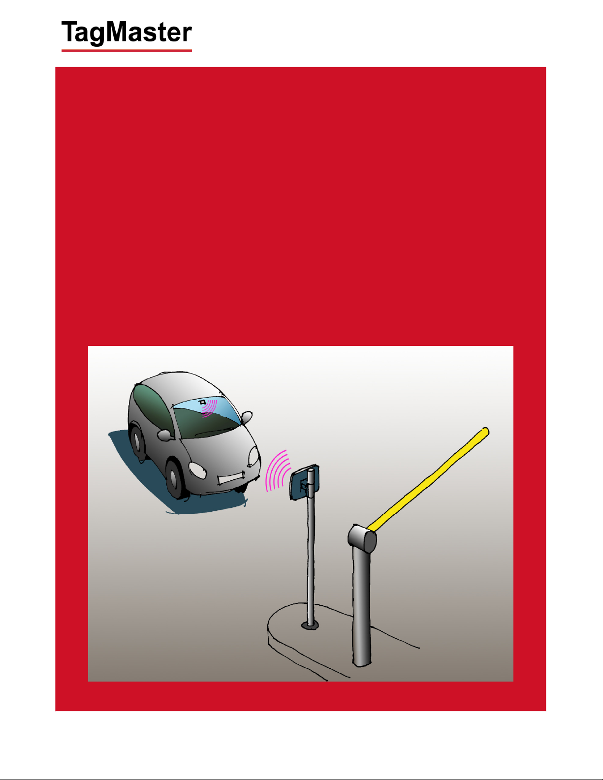
XT-1
Installation Manual
Page 2

XT-1 Installation Manual 13-111 P01B, 2013-RO-0XX, 2014-01-28
Note: This equipment has FCCID: M39XTXX. It complies with the limits for a Class A digital device,
pursuant to part 15 of the FCC Rules. These limits are designed to provide reasonable protection against
harmful interference when the equipment is operated in a commercial environment. This equipment
generates, uses, and can radiate radio frequency energy and, if not installed and used in accordance with
the instruction manual, may cause harmful interference to radio communications. Operation of this
equipment in a residential area is likely to cause harmful interference in which case the user will be
required to correct the interference at his own expense.
Caution: Changes or modifications not expressly approved by the party responsible for compliance could
void the user’s authority to operate the equipment.
Caution: To comply with Council Recommendation 1999/519/EC and FCC regulations, this reader must be
installed to provide a separation distance of at least 25 cm from all persons and must not be co-located or
operating in conjunction with any other antenna or transmitter.
Copyright
The copyright and ownership of this document belongs to TagMaster AB. The document may be
downloaded or copied provided that all copies contain the full information from the complete document. All
other copying requires a written approval from TagMaster AB.
Disclaimer
While effort has been taken to ensure the accuracy of the information in this document TagMaster AB
assumes no responsibility for any errors or omissions, or for damages resulting from the use of the
information contained herein. The information in this document is subject to change without notice.
Page 2 of 32
Page 3

XT-1 Installation Manual 13-111 P01B, 2013-RO-0XX, 2014-01-28
Content
1 Introduction 4
1.1
1.2
1.3
2 Installation 4
2.1
2.2
3 Interfaces 6
3.1
3.2
3.2.1 Terminal Connections .................................................................................... 8
3.2.2 Ethernet and USB .......................................................................................... 8
3.3
3.4
3.4.1 Wiegand Timing ........................................................................................... 11
3.4.2 Magstripe Timing ......................................................................................... 12
3.5
3.6
3.7
3.8
3.9
3.10
3.11
3.12
3.12.1 DIP SW S101 .............................................................................................. 21
3.12.2 DIP SW S301 .............................................................................................. 21
3.13
Overview........................................................................................................ 4
Tags .............................................................................................................. 4
Security ......................................................................................................... 4
Safety Instructions ......................................................................................... 4
Mounting Instruction ...................................................................................... 4
Cables ........................................................................................................... 6
Wires ............................................................................................................. 8
Power Supply ................................................................................................ 9
Wiegand/Magstripe ...................................................................................... 10
Ethernet ....................................................................................................... 13
RS232 ......................................................................................................... 14
RS485 ......................................................................................................... 15
USB ............................................................................................................. 17
Input ............................................................................................................ 18
Output .......................................................................................................... 19
Relay ........................................................................................................... 20
DIP Switches ............................................................................................... 21
LED and Buzzer........................................................................................... 22
4 Configuration 22
4.1
4.2
4.3
5 TAGP 22
6 Trouble Shooting 23
7 Technical Specification 31
PC Tool ....................................................................................................... 22
Settings ....................................................................................................... 22
Reset to Factory Default .............................................................................. 22
Page 3 of 32
Page 4

XT-1 Installation Manual 13-111 P01B, 2013-RO-0XX, 2014-01-28
1 Introduction
Overview
1.1
The XT-1 is an UHF RFID reader compliant with EPC Gen 2 (ISO 18000-6C). The reader is specifically
tailored for Automated Vehicle Identification (AVI) applications such as Parking, Gated Communities and
Condominiums. It has been designed for absolutely premium performance for read-range and
environmental specification while also giving a large number of interface options and having an innovative
implementation for TCP/IP connectivity and monitoring.
1.2
XT-1 supports any UHF tag compliant with the EPC Gen 2 standard. XT-1 also supports the
SecureMarkID® format developed by TagMaster to ensure that each tag has a truly unique identity difficult
to duplicate.
1.3
The EPC Gen 2 standard was initially developed for low cost item management and has for that reason no
built in support for encryption like DES or AES. This differentiates the system from for instance many
proximity identification systems. To address this TagMaster has developed the SecureMarkID® format
using a specific algorithm and non-writeable parts of the tag to create a truly unique identity difficult to
duplicate. It is recommend to only use SecureMarkID® tags together with XT-1, but also to consider these
limitations in any application requiring high security.
As the development of a cryptographic framework for EPC Gen2 proceeds, TagMaster will offer future new
products to continue to make the most of available technology in an effort to offer the highest possible
security.
Tags
Security
2 Installation
2.1
The following safety instruction should be observed during installation, normal use and service.
The installation and service should only be done by qualified personnel.
Shields of cables should be connected to safety ground.
The XT-1 must be disconnected from all voltage sources before any installation or service work.
Do not modify any part of the product. Repair is to be performed by TagMaster only.
Where local regulations exist, these are to be followed. The safety information in this manual is a
Safety Instructions
Capacitors inside the XT-1 can hold their charge even if the equipment has been disconnected from
all voltage sources.
supplement to local regulations. It is the responsibility of the local project manager to make certain
that local regulations are known and followed.
2.2
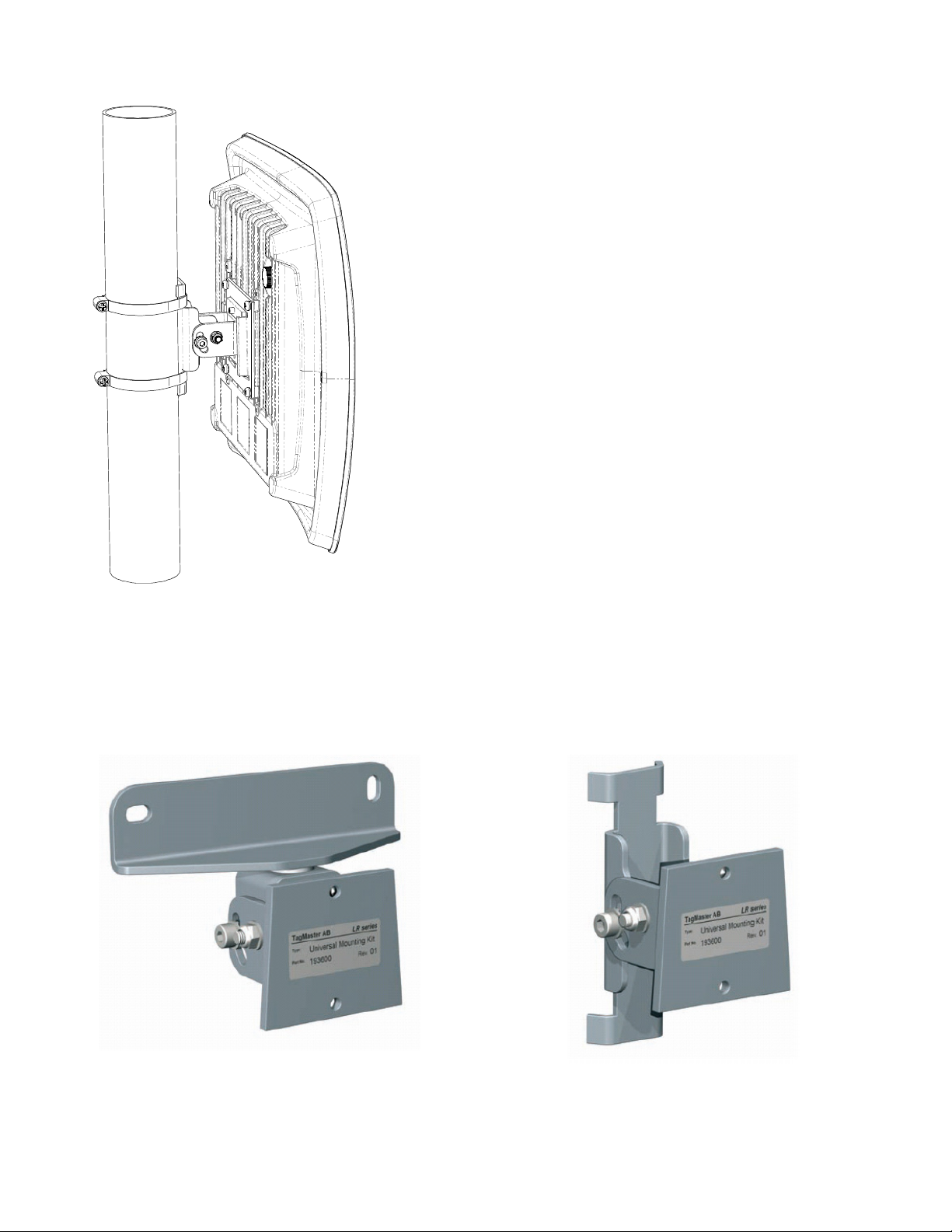
The XT-1 can be mounted to a wall or a pole, see Figure 1. Mount the reader in a horizontal position with
the cable glands on the bottom side. Direct the reader so that the reading lobe covers the positions of the
tags. For optimal performance, tilt and rotate the reader into a position so that the front side of the reader is
parallel with the front side of the tag to be read. Align the reader so that the actual reading range is 60–70%
of the specified maximum.
Mounting Instruction
Page 4 of 32
Page 5
XT-1 Installation Manual 13-111 P01B, 2013-RO-0XX, 2014-01-28
Figure 1 XT-1 mounted on a pole using UMK
The UMK (Universal Mounting Kit, Part No. 193600), see Figure 2, from TagMaster enables the reader to
be mounted in a wide variety of positions and angles. The kit contains all parts needed for mounting the
reader on a wall or on a pole. The UMK is suitable for outdoor use. See separate data sheet for more
details on installation.
Figure 2 UMK for wall and pole mounting of XT-1
Page 5 of 32
Page 6
XT-1 Installation Manual 13-111 P01B, 2013-RO-0XX, 2014-01-28
1
2
3 Interfaces
3.1
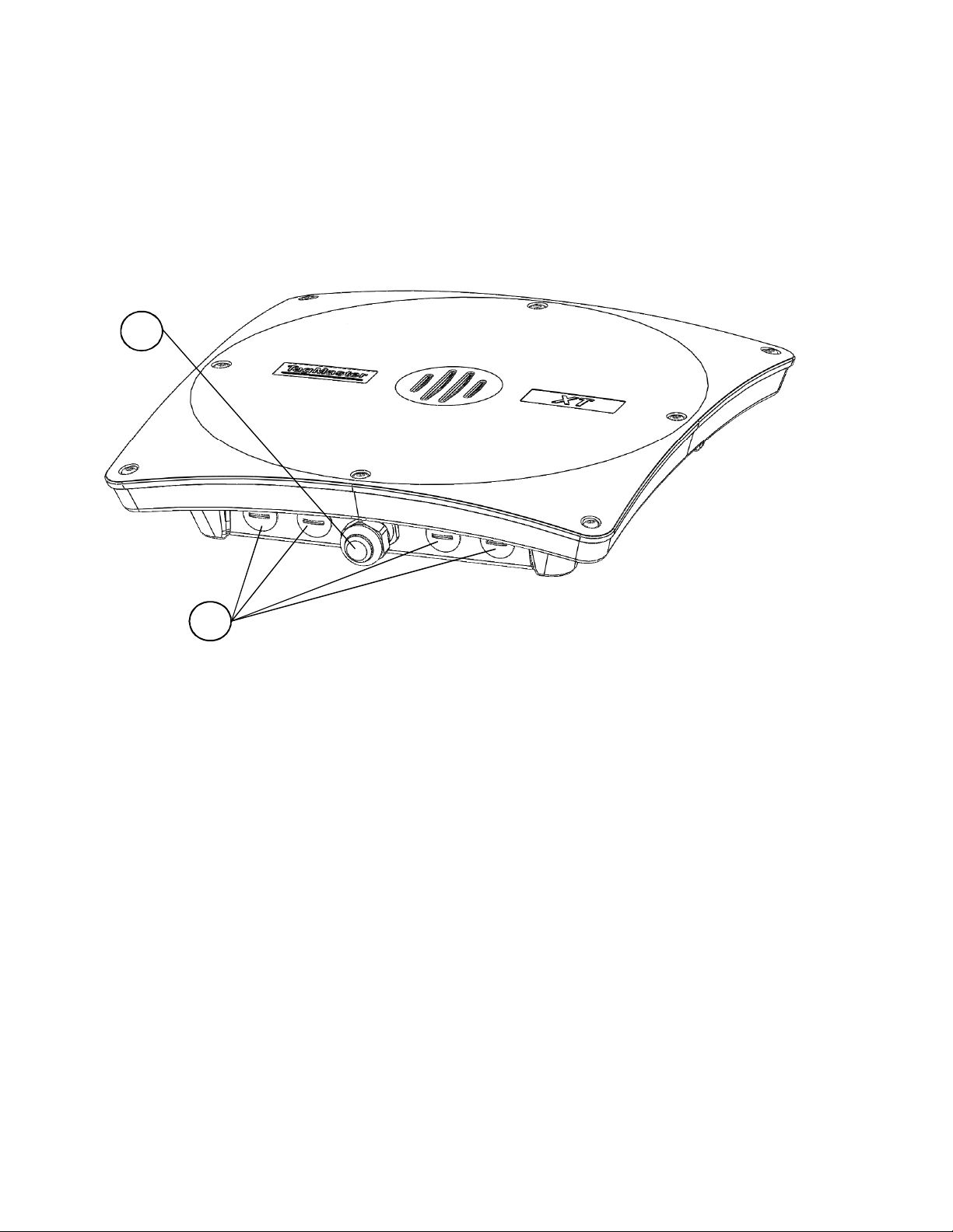
Connections to the XT-1 is primarily done using the central M20 cable gland, and secondarily by replacing
any of the 4 pcs of M16 blind stops with cable glands, see Figure 3. Shielded cables should be used for all
connections. Select cables suitable for the installation environment, considering indoor or outdoor
environment and use flexible cables with stranded wire. The reader chassis should be grounded.
Cables
Figure 3 Cable connections for XT-1 (Pos. 1 is M20 cable gland, Pos. 2 is M16 blind stops)
Instructions:
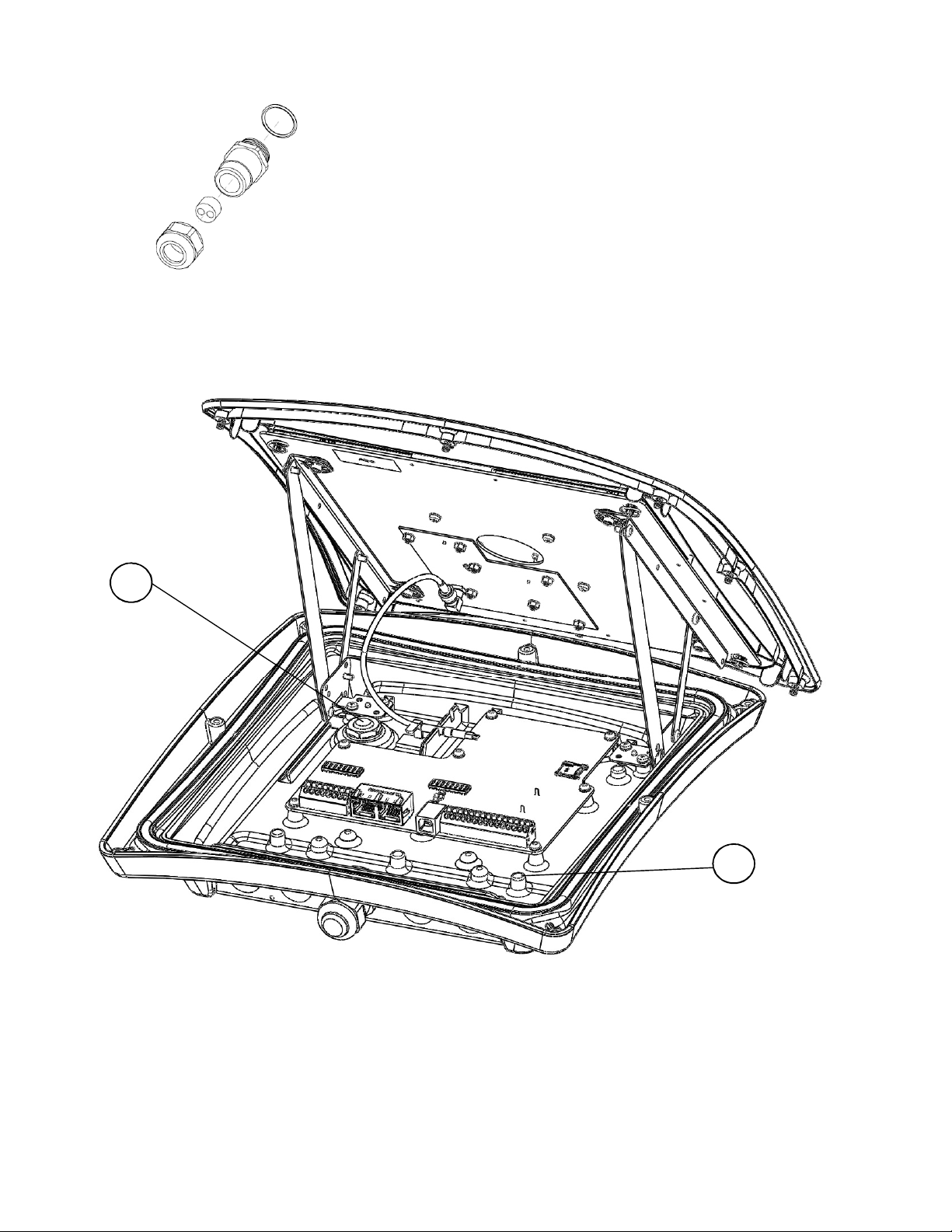
1. Select and use the M20 cable gland insert corresponding to the number of cables required. The
cable gland can be used with one cable (6-12 mm) or by using the supplied insert with two cables
(2-6 mm), see Figure 4.
2. Open XT-1 lid by removing the 8 screws on the front, and slide the lid open.
3. Feed the cable (or two cables) through the cable gland and through the chassis. All parts of the
cable gland except the nut shall be on the outside of the XT-1.
4. Connect the wires to relevant terminals and connections depending on interfaces being used. If
using RJ45 connectors for Ethernet these must be crimped inside the reader.
5. Connect the shielding of the power cable to the chassis grounding point using the grounding screw
(Figure 5, Pos. 1).
6. Screw the cable gland to tighten and ensure proper water and dust sealing.
As an alternative for grounding, a metallic cable gland (not included) can be used to connect to the reader
chassis to ground using the power cable shielding.
Page 6 of 32
Page 7
XT-1 Installation Manual 13-111 P01B, 2013-RO-0XX, 2014-01-28
1
2
Figure 4 The XT-1 M20 cable gland with insert for 2 cables
Never use the ventilating membrane (Figure 5, Pos. 2) on the back of the XT-1 for cable connections.
Figure 5 XT-1 overview (Pos. 1 is ground screw connection, Pos.2 is ventilating membrane)
Page 7 of 32
Page 8
XT-1 Installation Manual 13-111 P01B, 2013-RO-0XX, 2014-01-28
3.2
Wires
3.2.1 Terminal Connections
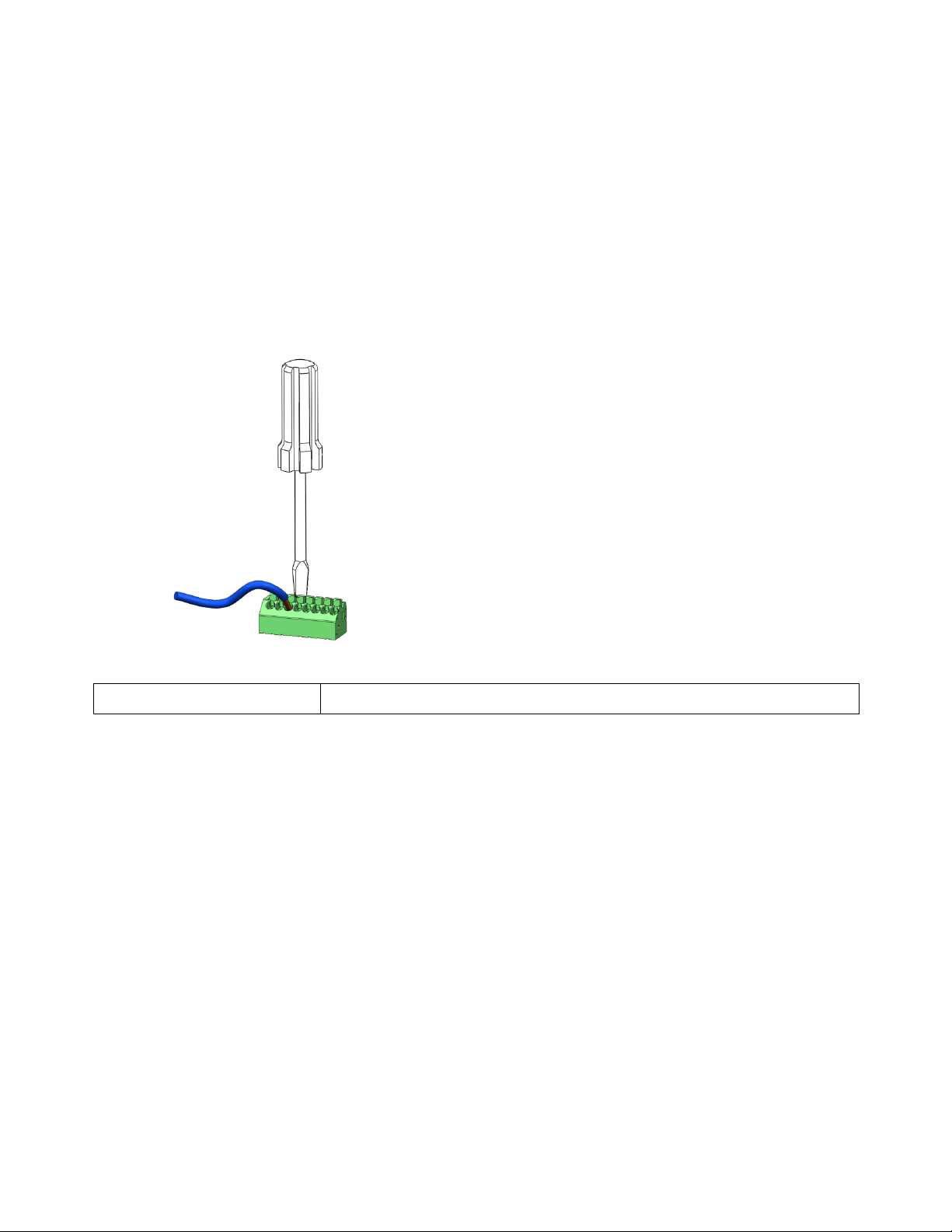
Wire connections (with the exception of Ethernet and USB, see §3.2.2) are added as singles wires to spring
cage terminal connectors, see Figure 6. These are easy-to-use terminals for single stranded wires.
Instructions:
1. Strip wire lead approximately 9 mm.
2. Push screwdriver down to release spring cage.
3. Insert wire into terminal.
4. Remove screwdriver which will clamp wire.
5. Gently pull installed wire to make sure connection is reliable.
Figure 6 Connection with easy-to-use spring cage terminal
Wire size 0.5mm2 - 1.5mm2 / AWG20 - AWG 16
Table 1 Wire connection overview
3.2.2 Ethernet and USB
Ethernet is connected using RJ45 connectors. To be able to fit this connector given the limited diameter of
M20 cable gland and the hole in the chassis, such RJ45 must be crimped to the wires inside the reader.
This is done with corresponding standard tool and RJ45. Pass the Ethernet cable through the cable gland
before crimping the connector on the cable.
USB is intended for service interface and therefore connected only when lid is open. Connection is done
using a standard USB type B cable.
Page 8 of 32
Page 9
XT-1 Installation Manual 13-111 P01B, 2013-RO-0XX, 2014-01-28
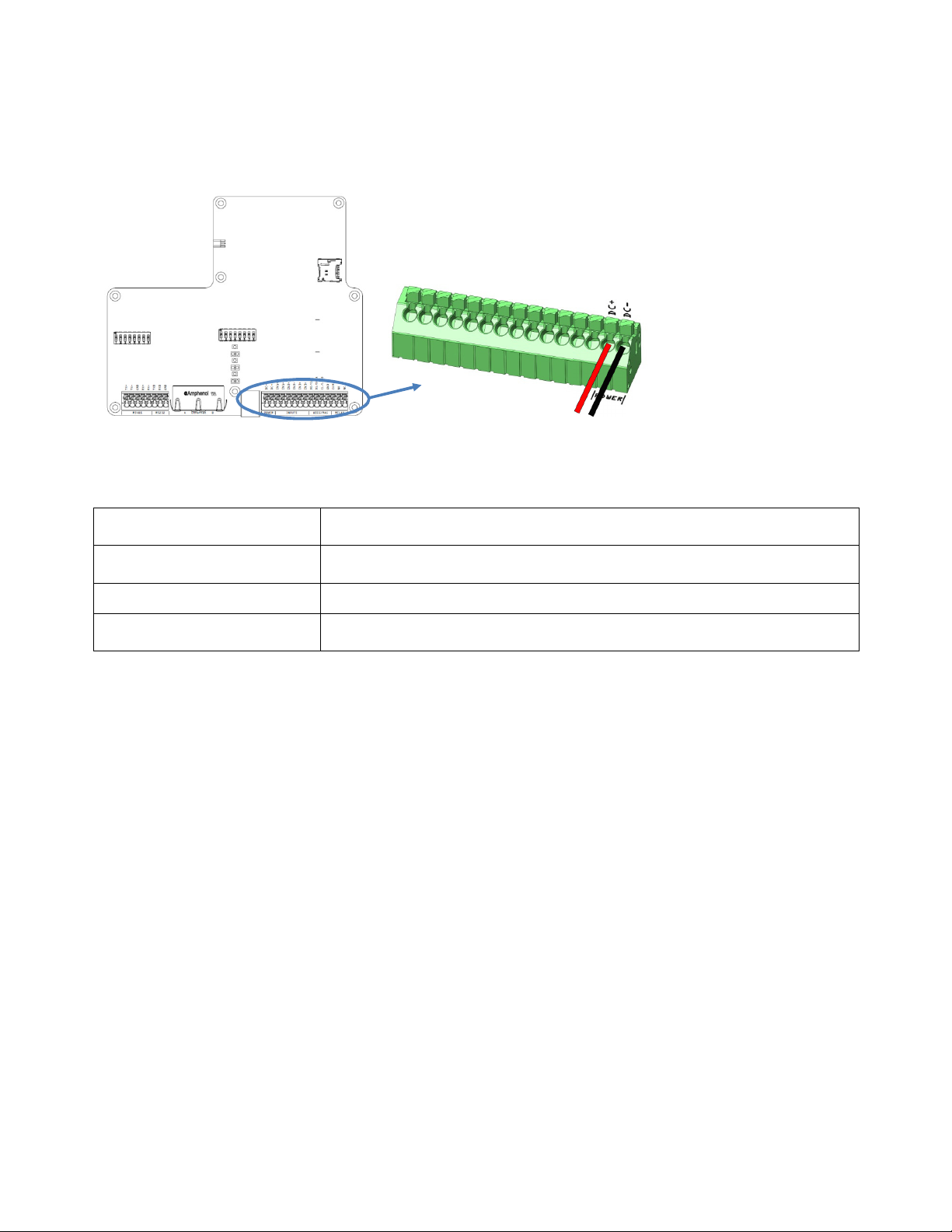
DC+
High supply potential
(See
Figure
7 for details
)
3.3
The XT-1 shall be powered by an isolated power supply suitable for outdoor use. The required voltage is 12
VDC to 24VDC. It is recommended to use a power supply of 24 VDC, 1 A minimum.
Power Supply
Figure 7 Power supply connection, overview and detail
The power input has built-in protection for an accidental connection of reversed polarity.
Connections
Supply voltage
Recommended / Max length 10m / 100m
Wire size
Table 2 Power connection overview
DC- Low supply potential
12 VDC to 24 VDC
(Absolute minimum rating 10 VDC, absolute maximum rating 30 VDC)
Recommended length 0.5mm2 / AWG 20
Max length 1.5mm2 / AWG 16
Page 9 of 32
Page 10
XT-1 Installation Manual 13-111 P01B, 2013-RO-0XX, 2014-01-28
3.4
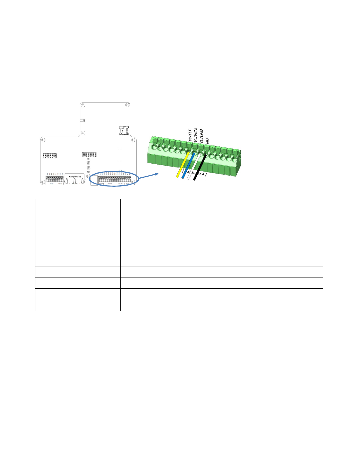
The Wiegand interface is shared with Magstripe and outputs. This selection of interface is done via SW
configuration see §4. Furthermore is the details of the Wiegand output format configured using SW. The
interface has a separate isolation of 1500 VDC and varistor protection for over voltage.
The XT-1 has a built-in option (3xDIP) of 1kΩ pull-ups on the transmit side for D0/CLK, D1/DATA and
CL/LOAD. The DIP switches are also described in §3.12.
Wiegand/Magstripe
Figure 8 Wiegand connection, overview and detail
D0 Wiegand 0 (See Figure 8 for details)
Connections
(Wiegand)
Connections
(Magstripe)
Recommended / Max length 10m / 100m (depending on properties of receiving system)
Wire size 0.5mm2 / AWG 20
Voltage 30 V (Max)
Sink current 50 mA (Max)
Isolation 1500 VDC (Min)
Table 3 Wiegand connection overview
D1 Wiegand 1
CL Card Load
GND Ground
CLK Magstripe clock (See Figure 8 for details)
DATA Magstripe data
LOAD Card load
GND Ground
Page 10 of 32
Page 11
XT-1 Installation Manual 13-111 P01B, 2013-RO-0XX, 2014-01-28
Symbol
Parameter
Min Typ Max
Unit
µ
tPW
Pulse width
80
µ
tH
CL hold time after
last D# change
0
µ
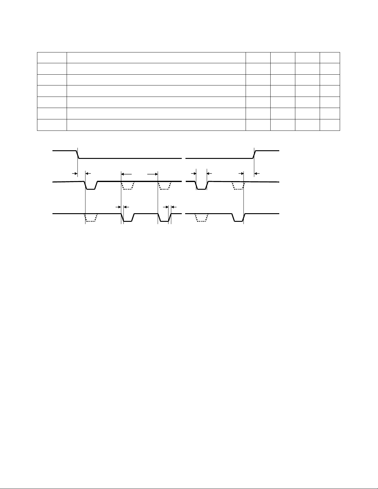
3.4.1 Wiegand Timing
The following values apply when all outputs are pulled up to 5V with 1kΩ resistors.
tSU CL to D# setup time 0
tF Fall time (all signals) 125 ns
tR Rise time (all signals) 5
tPI Pulse interval 2 ms
Table 4 Wiegand interface timing
t
R
≈ ≈ ≈
t
PW
t
H
CL
t
SU
D0
D1
Figure 9 Wiegand timing diagram
t
PI
t
F
Description on default output format to be added in later revision.
s
µs
s
s
Page 11 of 32
Page 12
XT-1 Installation Manual 13-111 P01B, 2013-RO-0XX, 2014-01-28
Symbol
Parameter
Min Typ Max
Unit
µ
tCH
Clock high
160 µ
tH
LOAD hold time after last CLK change
0
µ
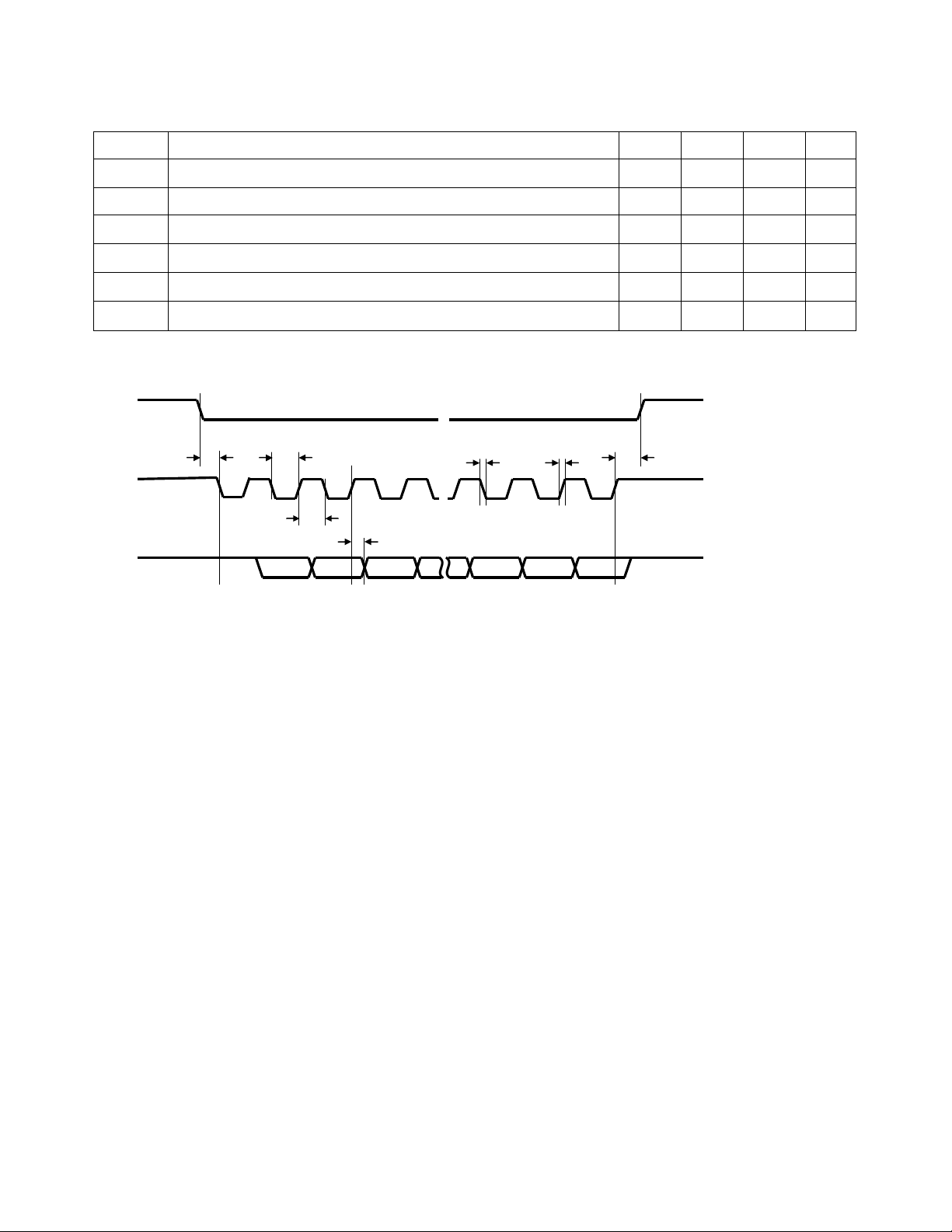
3.4.2 Magstripe Timing
The following values apply when all outputs are pulled up to 5V with 1kΩ resistors.
tSU LOAD to CLK setup time 0
tF Fall time (all signals) 125 ns
tR Rise time (all signals) 5
tCL Clock low 160
Table 5 Magstripe interface timing
LOAD
CLK
t
SU
t
CL
t
CH
t
DH
≈
≈
t
t
F
R
t
H
≈
DATA
Figure 10 Magstripe timing diagram
s
µs
µs
s
s
Description on default output format to be added in later revision.
Page 12 of 32
Page 13
XT-1 Installation Manual 13-111 P01B, 2013-RO-0XX, 2014-01-28
Example:
3.5
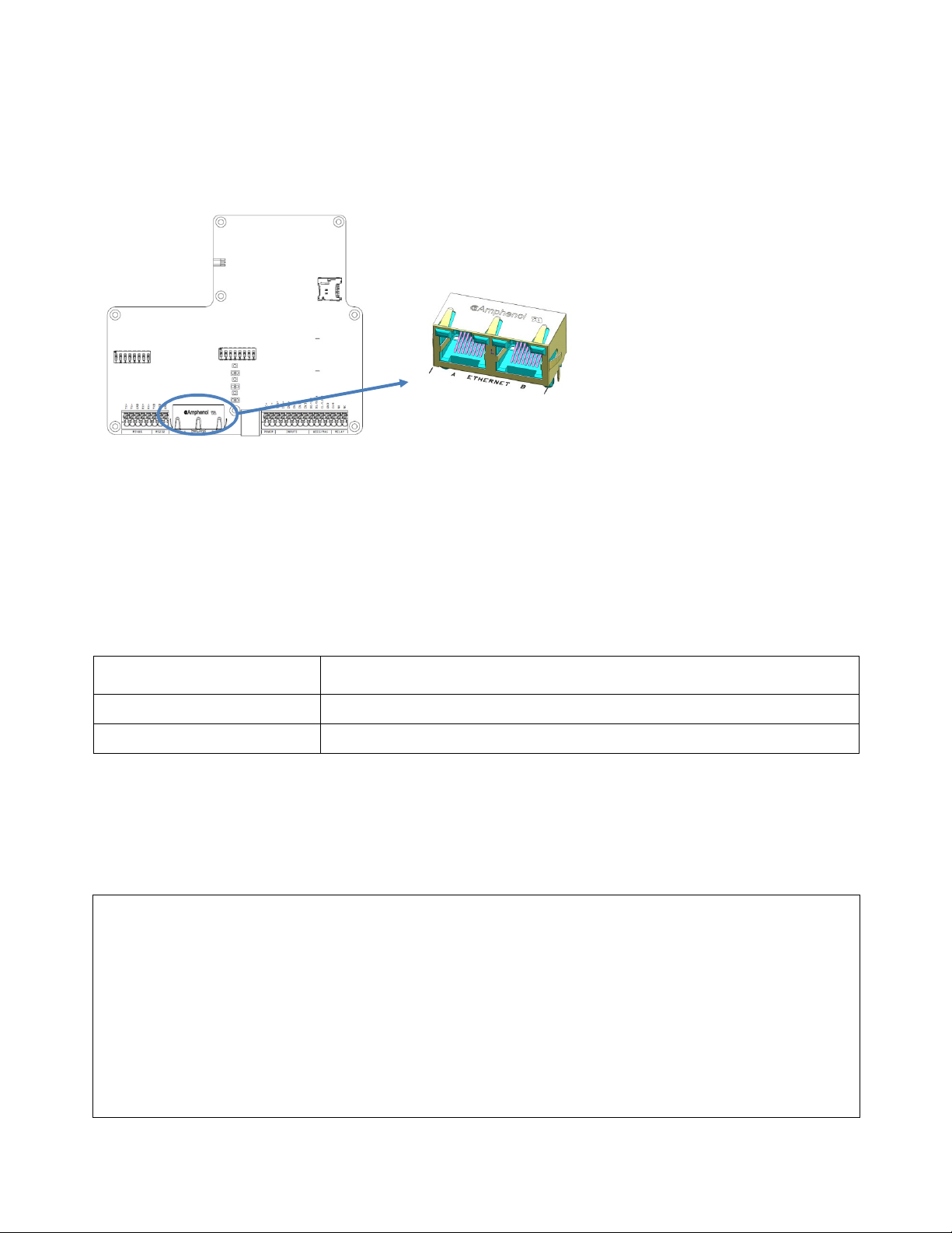
The XT-1 has a built in 10Mbps/100Mbps Ethernet switch and dual ports. This makes it possible to connect
a number of readers in a system without the need for additional network equipment. The two ports A and B
are using RJ45 connectors and are fully equivalent.
Ethernet
Figure 11 Ethernet connection, overview and detail
The XT-1 supports auto crossover (Auto-MDIX) so that installation can be done using both patch and
crossover cables. The connectors have eight pins and the wire scheme is based on the T568A standard.
The interfaces have separate isolation of 1500 VDC.
The default IP address of the device is unique among XT-1 readers and can be found on the label on the
back of the XT-1. This makes it possible to create a stand-alone network without changing any reader
network settings. Detailed network settings are configured using SW, see §4. Each port has two LED
indicators for Link/Activity (Yellow/Flashing Yellow) and 10Mbps/100Mbps speed (Off/Green).
Connections
Recommended / Max length - / 100m
Wire size CAT5e cable is required for the Ethernet connection
Table 6 Ethernet connection overview
Ethernet communication is normally done using TagMaster protocol TAGP available at port 9999. See
Manual 05-172 TAGP Protocol Specification for details.
A Port A (See Figure 11 for details)
B Port B
The following is an example on how a connection using Ethernet, TCP/IP and TAGP can be tested
1. Download PUTTY-TE from TagMaster ftp-server ftp://partner:[email protected]
2. Open a connection with PUTTY-TE using the IP address of the XT-1 and selecting TAGP
3. Write the following sequence to get a 2.5s beep from the reader:
User input XT-1 response
HELOTAGP/2.0 RPLYHELO00
PUSHBEEP9C9 RPLYPUSH00
Table 7 Ethernet connection example
Page 13 of 32
Page 14
XT-1 Installation Manual 13-111 P01B, 2013-RO-0XX, 2014-01-28
Specification according to EIA RS232C. Belden 9184 or Belden 9502 are
3.6
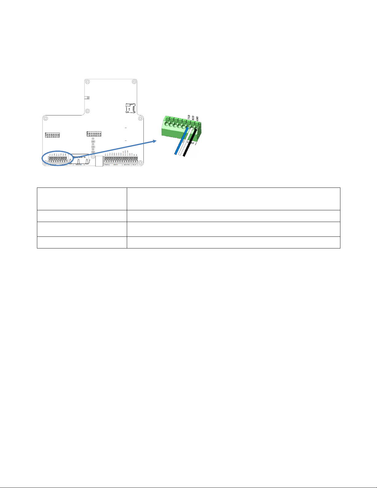
The RS232 interface is used for host communication and supports ASCII output and TAGP. Detailed
settings are configured using SW, see §4. The interface has a separate isolation of 1500 VDC and varistor
protection for over voltage.
Figure 12 RS232 connection, overview and detail
Connections
Recommended / Max length - / 10m
RS232
TXD Transmitted data to host (See Figure 12 for details)
RXD Received data from host
GND Ground
Wire size
Max Baud Rate 115.2 kb/s (default)
Table 8 RS232 connection overview
The default output of the RS232 interface is a one directional ASCII output of tag data. If SecureMarkID®
tags from TagMaster are being used (recommended) this identity is sent followed by CR+LF ('\r''\n'). If other
EPC tags are being used the default output is the EPC data followed by CR+LF ('\r''\n').
As an alternative can TAGP be selected as format if configured using SW.
recommended.
Page 14 of 32
Page 15
XT-1 Installation Manual 13-111 P01B, 2013-RO-0XX, 2014-01-28
SW#1 SW#
2 SW#
5
SW#
3
SW#
4
120 Ω
620 Ω
620 Ω
3.7
RS485
The RS485 interface is used for host communication and supports ASCII output and TAGP. It generally
supports longer transmission distances than RS232. Detailed settings are configured using SW, see §4.
The interface has a separate isolation of 1500 VDC and varistor protection for over voltage.
Figure 13 RS485 connection, overview and detail
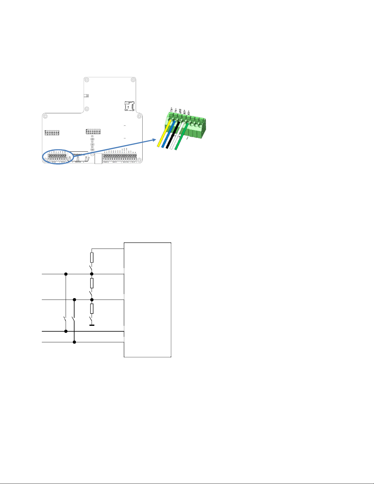
The hardware supports 2- wire (2xDIP) and 4-wire communication, half duplex and full duplex as well as
multi-drop. When using RS485 communication, correct termination of the interface must always be
considered in order to handle transmission-line effects. The XT-1 has a built-in option (DIP) of 120Ω
termination on the receive side, and an option (2xDIP) of 600Ω bias on receive side. The options using DIP
switches are detailed in Figure 14 and also described in §3.12.
5V iso
RX+
RX-
TX+
TX-
RS485
driver
Figure 14 RS485 DIP switch configuration options
Page 15 of 32
Page 16

XT-1 Installation Manual 13-111 P01B, 2013-RO-0XX, 2014-01-28
TX+ Transmitted data to host
(See
Figure
13 for details)
The cable for the RS485
interface must be a twisted pa
ir cable and
TX- Transmitted data to host
Connections
GND Ground
RX+ Received data from host
RX - Received data from host
Recommended / Max length - / 1000m
Wire size
conform to the EIA RS485 standard.
Max Baud Rate 115.2 kb/s (default)
Table 9 RS485 connection overview
The default output of the RS485 interface is a one directional ASCII output of tag data. If SecureMarkID®
tags from TagMaster are being used (recommended) this identity is sent followed by CR+LF ('\r''\n'). If other
EPC tags are being used the default output is the EPC data followed by CR+LF ('\r''\n').
As an alternative can TAGP be selected as format if configured using SW.
Page 16 of 32
Page 17
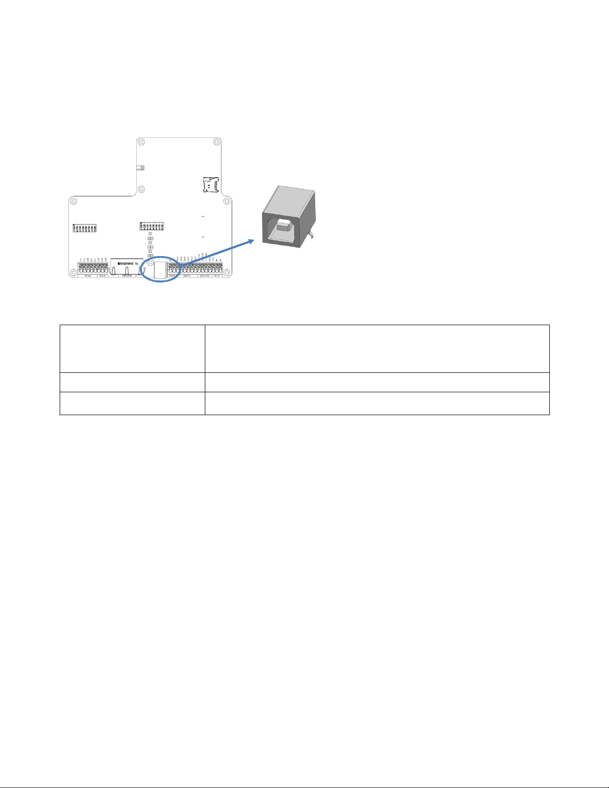
XT-1 Installation Manual 13-111 P01B, 2013-RO-0XX, 2014-01-28
VBUS
+5VDC (See
Figure
15 for details)
TBD
3.8
The XT-1 has one USB type B connector, and acts like a USB 2.0 Full-Speed (12 Mbps) device. This
interface is only intended for configuration and software download (service and maintenance). The interface
is connected using a standard cable to a USB port of a PC, and after installing specific TagMaster software
can maintenance be done, see §4.
USB
Figure 15 USB connection, overview and detail
Connections
Recommended / Max length 1m / TBD
Wire size
Table 10 USB connection overview
DM Data–
DP Data+
GND Ground
Page 17 of 32
Page 18
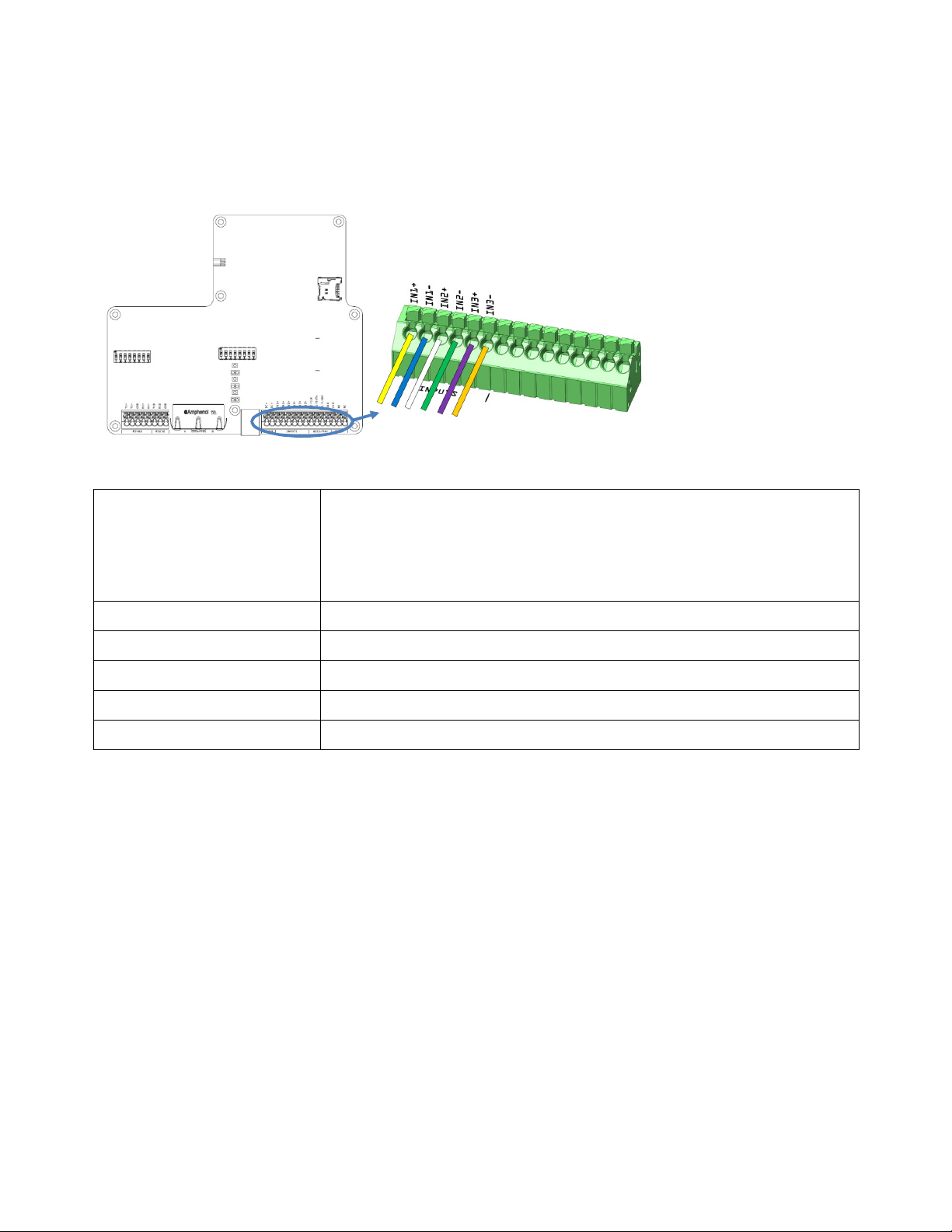
XT-1 Installation Manual 13-111 P01B, 2013-RO-0XX, 2014-01-28
IN1+
Presence detector input+
(See
Figure
16 for details)
3.9
The XT-1 has 3 inputs available. The inputs are opto-coupled, have 1500VDC isolation and protection for
reversed polarity. They have an input impedance of 1kΩ and are activated by a current flow. The inputs are
intended for optional connection to detectors (inductive loop, IR or other type). The types are ‘Presence
detector input’, ‘Safety detector input’ and ‘Opening detector input’.
Input
Figure 16 Input connections, overview and detail
IN1- Presence detector input-
Connections
High Voltage (active) Min 3.0 V / Max 30 V
Low Voltage (inactive) Min 0.0 V / Max 0.2 V
Input impedance 1 kΩ
Recommended / Max length 10m / 100m
Wire size 0.5mm2 / AWG 20
Table 11 Input connection overview
IN2+ Safety detector input+
IN2- Safety detector input-
IN3+ Opening detector input+
IN3- Opening detector input-
Page 18 of 32
Page 19
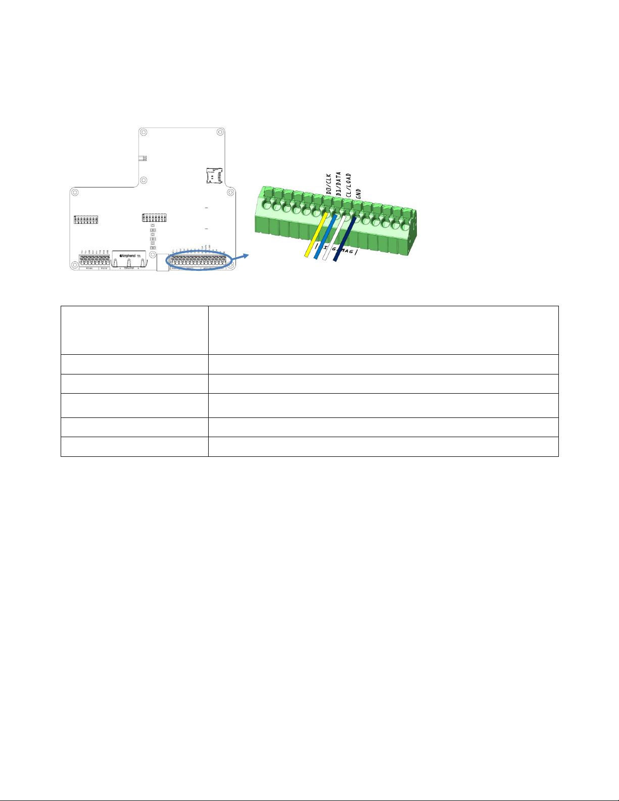
XT-1 Installation Manual 13-111 P01B, 2013-RO-0XX, 2014-01-28
D0 Output 0 (See
Figure
17 for details)
Min 10 V / Max 30 V
3.10
The XT-1 has 3 open-collector outputs shared with Wiegand/Magstripe available. These are currently
intended for future use and have no specific functionality assigned (other than Wiegand/Magstripe). The
interface has an isolation of 1500VDC.
Output
Figure 17 Output connections, overview and detail
Connections
Applied Voltage Min 1.0 V / Max 30 V
Sink Current Min 0.0 mA / Max 500 mA
Supply
Recommended / Max length 10m / 100m
Wire size 0.5mm2 / AWG 20
Table 12 Output connection overview
D1 Output 1
CL Output 2
GND Ground
Min 3 mA / Max 9 mA
Page 19 of 32
Page 20
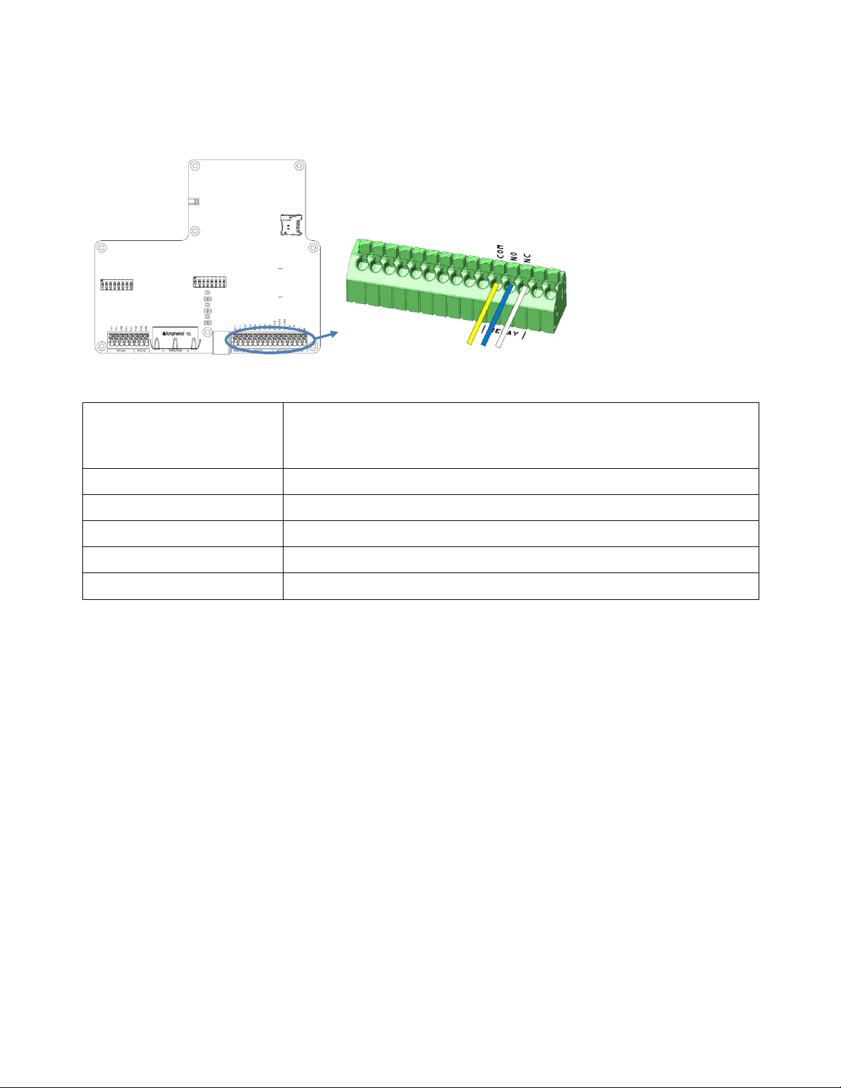
XT-1 Installation Manual 13-111 P01B, 2013-RO-0XX, 2014-01-28
COM
Common (See
Figure
18 Figure
18 Relay connections, overview
3.11
The XT-1 has a non-latching relay available. It is typically connected to the logic controlling a barrier, gate
or other object when the reader is in stand-alone operation.
Figure 18 Relay connections, overview and detail
Connections
Switching current Max 2A
Relay
and detailfor details)
NO Normally Open
NC Normally Closed
Switch voltage Max. 60VDC / 30VAC
Switching capacity: Max. 60W / 62,5VA
Recommended / Max length 10m / 100m
Wire size 0.5mm2 / AWG 20
Table 13 Output connection overview
Page 20 of 32
Page 21
XT-1 Installation Manual 13-111 P01B, 2013-RO-0XX, 2014-01-28
Firmware upgrade mode. Toggle to ‘On’
and cycle power
before firmware upgrade using
3.12
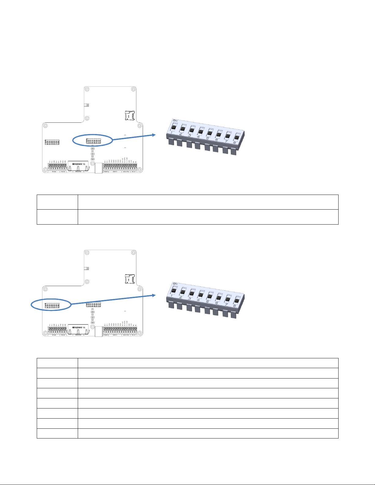
Two DIP switches (8 positions) are available for physical configuration of a few major parameters. All other
configurations are done using software. Default state for all switches is ‘Off’.
DIP Switches
3.12.1 DIP SW S101
Figure 19 DIP SW S101, overview and detail
Position 1
Position 2
USB. Return to ‘Off’ after upgrade complete.
Restore factory default settings. Toggle to ‘On’ and cycle power for complete reader reset.
Return to ‘Off’ after restore complete.
3.12.2 DIP SW S301
Figure 20 DIP SW S301, overview and detail
Position 1 Enable RS485 2-wire mode, TX+ <-> RX+ (always together with Position 2)
Position 2 Enable RS485 2- wire mode, TX- <-> RX- (always together with Position 2)
Position 3 Enable RS485 120Ω termination between RX+ and RX-
Position 4 Enable bias RS485 620 Ω RX+, up
Position 5 Enable bias RS485 620 Ω RX-, down
Position 6 Enable 1 kΩ pull-up D0/CLK
Position 7 Enable 1 kΩ pull-up D1/DATA
Position 8 Enable 1 kΩ pull-up CL/LOAD
Page 21 of 32
Page 22
XT-1 Installation Manual 13-111 P01B, 2013-RO-0XX, 2014-01-28
3.13
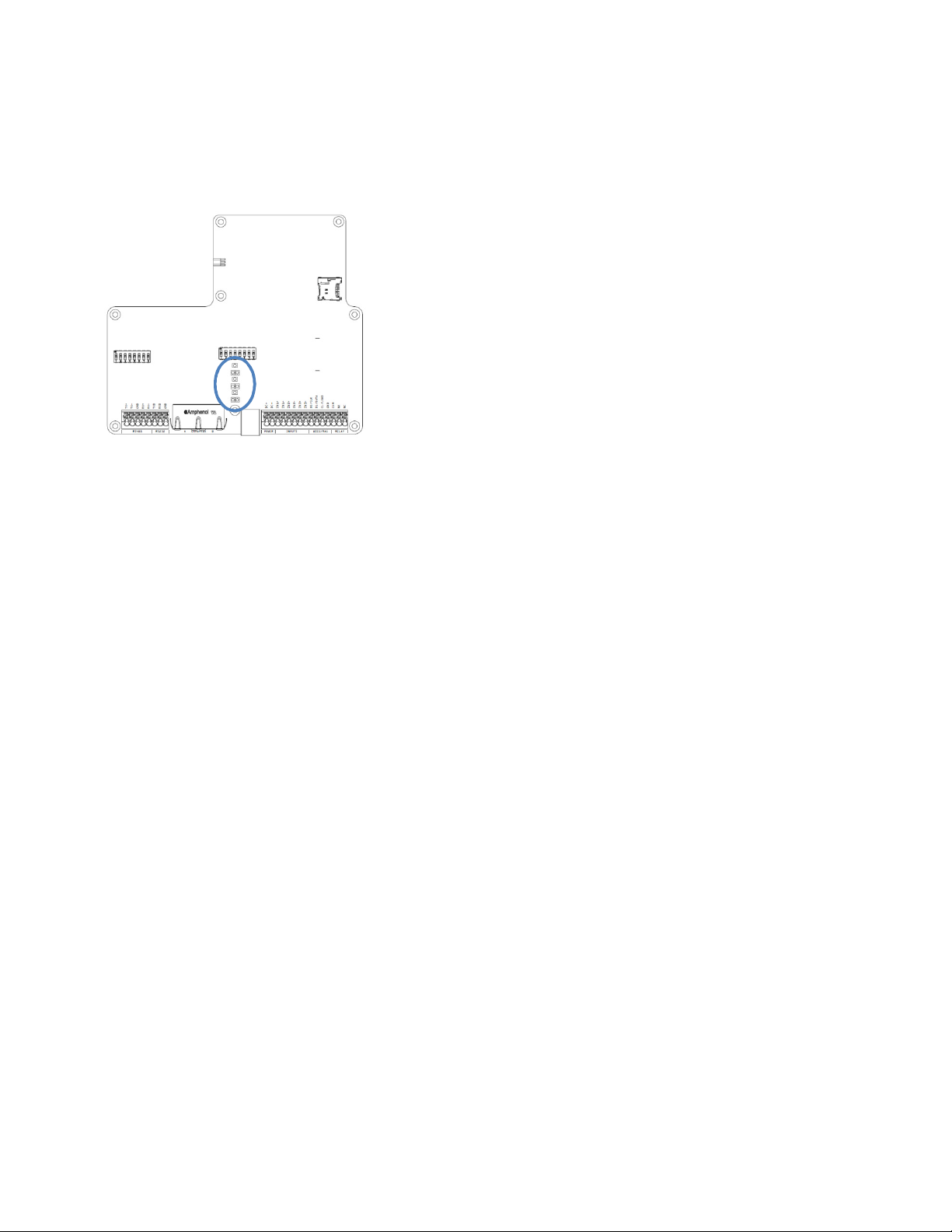
The XT-1 is equipped with bright LEDs for external signalling. These can indicate red/green/yellow based
on software settings. Default signalling is green for ‘tag read’/’ tag accepted’ and red for ’tag not accepted’
The buzzer is default off, but can be enabled for indicating ‘tag read’/’tag accepted’.
LED and Buzzer
Figure 21 LED, overview
4 Configuration
4.1
A PC tool is available for reader communication and firmware download.
4.2
The available settings can be found in the PC Tool. Generally these settings includes necessary
configuration for networking, interface output and reader behaviour.
4.3
To restore the reader back to the factory defaults state toggle the corresponding DIP switch (see §3.12) to
‘On’ and cycle the power. Wait for a few seconds, return the DIP switch to ‘Off’ and then cycle power again.
After a reset to factory defaults all software settings are reverted back to the original state. The IP-address
of the device is again the one printed on the label on the back of the reader.
PC Tool
Settings
Reset to Factory Default
5 TAGP
The protocol TAGP is available on Ethernet, RS232 and RS485 interfaces.
Page 22 of 32
Page 23

XT-1 Installation Manual 13-111 P01B, 2013-RO-0XX, 2014-01-28
6 Trouble Shooting
To facilitate trouble shooting, consider the following:
Make sure the XT-1 has correct supply voltage with sufficient current. There is a small green LED
on the electronic board, only visible when the lid of the reader is in open position. A flashing green
light of this LED indicates that power is connected and that the microcontroller is alive.
If using Ethernet communication, make sure that the network connection is ok. There are small
LEDs of the RJ45 socket, only visible when the lid of the reader is in open position. A yellow light
indicates ‘Link’ and flashing yellow light indicates ‘Activity’.
If the software settings might have been set to unclear state or the IP-address mixed up, a reset to
factory default operation is recommended, see §4.3.
Make sure that working and correctly formatted EPC Gen 2 tags are being used.
.
Page 23 of 32
Page 24

XT-1 Installation Manual 13-111 P01B, 2013-RO-0XX, 2014-01-28
Page 24 of 32
Page 25

XT-1 Installation Manual 13-111 P01B, 2013-RO-0XX, 2014-01-28
Page 25 of 32
Page 26

XT-1 Installation Manual 13-111 P01B, 2013-RO-0XX, 2014-01-28
Page 26 of 32
Page 27

XT-1 Installation Manual 13-111 P01B, 2013-RO-0XX, 2014-01-28
Page 27 of 32
Page 28

XT-1 Installation Manual 13-111 P01B, 2013-RO-0XX, 2014-01-28
Page 28 of 32
Page 29

XT-1 Installation Manual 13-111 P01B, 2013-RO-0XX, 2014-01-28
Page 29 of 32
Page 30

XT-1 Installation Manual 13-111 P01B, 2013-RO-0XX, 2014-01-28
Page 30 of 32
Page 31

XT-1 Installation Manual 13-111 P01B, 2013-RO-0XX, 2014-01-28
7 Technical Specification
Operating frequencies Area 1: 865.6-867.6 MHz Europe,
Area 2: 902-928 MHz US, Americas
Read range Up to 8 meters (20ft) with TagMaster UHF tags with
SecureMarkID®; Windshield ID-tag and Credit Card ID-tag
Dimensions 300x300x60 mm (11.8x11.8x2.4 in)
Weight 2.3 kg (5.1 lbs)
Protection IP 66
Operating temperature -40°C to +60°C (-40°F to +140° F)
EN 60068-2-1 Ad, En 60068-2-2 Bd, EN 60068-2-14 Nb
Storage temperature -40°C to +85C°C (-40°F to +185°F)
Relative humidity 93%RH @ 65C
EN 60068-2-30
Housing Aluminium housing UL94 certified XENOY™ cover
Power supply 12-24 VDC supply
Power consumption 10W (max 12W)
Output power Area 1 2W (e.r.p.), Area 2 4W (e.i.r.p.)
Input 3 isolated inputs
Output 3 isolated outputs shared with Wiegand/Magstripe
Relay 1 relay output 60VDC, 2A
Interfaces RS232, RS485, Wiegand/Magstripe, 2 pcs Ethernet and
USB service Interface
Certificates CE Certificate according to R&TTE-directive 1999/5/EC and FCC
RoHS Directive 2002/95/EC and 2011/65/EU
WEEE 2002/96/EC
Standards EPC Gen 2 (ISO 18000-6C)
LED indicator Res/Green/Yellow
Communications protocols TAGP and various OEM protocols
Encrypted air interface According to EPC Gen 2 (ISO 18000-6C)
EMC EN 301489-1, EN 301489-3
Radio EN 302 208-1, EN 302 208-2
FCC: CFR 47, Part 15 subpart C, FCC ID: M39XTXX
Safety & health EN 60950-1, EN 60950-22 & 1999/519/EC
Mechanical EN 60068-2-27 Ea, EN 60068-2-64 Fh
Manuals and documentation XT-1 Installation Manual, 13-111
TAGP Manual, 05-172
Part No. Area 1: 152500
Area 2: 152600
Page 31 of 32
Page 32

XT-1 Installation Manual 13-111 P01B, 2013-RO-0XX, 2014-01-28
Technical Support
Phone: + 46 8 632 19 50
Fax: +46 8 750 53 62
E-mail: [email protected]
Office Address
TagMaster AB
SE-164 46 KISTA
SWEDEN
Phone: +46 8 632 19 50
Fax: +46 8 750 53 62
E-mail: [email protected]
Web: www.tagmaster.com
Page 32 of 32
 Loading...