

Page 1
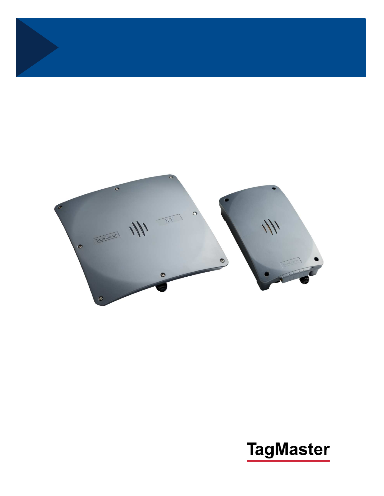
XT Series Reader
Manual
English
Page 2

XT Series Reader Manual 13-111 P11D, 2017-10-03
Note: This equipment has FCCID M39XTMX (XT Mini), M39XTXX (XT-1), or M39XTMEX (XT-5/XT-5 ETC).
It complies with the limits for a Class A digital device, pursuant to part 15 of the FCC Rules. These limits are
designed to provide reasonable protection against harmful interference when the equipment is operated in a
commercial environment. This equipment generates, uses, and can radiate radio frequency energy and, if
not installed and used in accordance with the instruction manual, may cause harmful interference to radio
communications. Operation of this equipment in a residential area is likely to cause harmful interference in
which case the user will be required to correct the interference at his own expense.
Warning: Operation of the equipment requires professional installation to correctly set the TX power for the
RF cable and antenna selected.
The users are prohibited from making any change or modifications to this product. Any modification to this
product shall void the user’s authority to operate under FCC Part 15 regulations.
This device complies with Part 15 of the FCC Rules. Operation is subject to the following two conditions: (1)
This device may not cause harmful interference and, (2) this device must accept any interference received,
including interference that may cause undesired operation.
Caution: Changes or modifications not expressly approved by the party responsible for compliance could
void the user’s authority to operate the equipment.
Caution: To comply with Council Recommendation 1999/519/EC and FCC regulations, this equipment must
be installed to provide a separation distance of at least 20 cm (XT Mini), 25 cm (XT-1) and 30 cm (XT-5 and
XT-5 ETC) from all persons and must not be co-located or operating in conjunction with any other antenna
or transmitter.
Page 2 of 36
Page 3

13-111 P11D, 2017-10-03 XT Series Reader Manual
Copyright
The copyright and ownership of this document belongs to TagMaster AB. The document may be downloaded
or copied provided that all copies contain the full information from the complete document. All other copying
requires a written approval from TagMaster AB.
Disclaimer
While effort has been taken to ensure the accuracy of the information in this document TagMaster AB
assumes no responsibility for any errors or omissions, or for damages resulting from the use of the information
contained herein. The information in this document is subject to change without notice.
Table of Contents
1 Introduction 5
Readers ......................................................................................................... 5
Tags .............................................................................................................. 5
SecureMarkID® .............................................................................................. 5
2 Installation 5
Safety Instructions ......................................................................................... 5
Reader and Tag Placement ........................................................................... 6
Mounting Instructions ..................................................................................... 8
2.3.1 Universal Mounting Kit (UMK) .................................................................... 8
2.3.2 Dimensions ................................................................................................ 8
Cable Connections ........................................................................................ 9
2.4.1 XT Mini ....................................................................................................... 9
2.4.2 XT-1 ........................................................................................................... 9
2.4.3 XT-5 / XT-5 ETC ...................................................................................... 10
Wire Connections ........................................................................................ 11
2.5.1 Spring Cage Terminals ............................................................................ 11
2.5.2 Ethernet and USB .................................................................................... 11
External Antennas ....................................................................................... 11
3 Interfaces 12
Overview...................................................................................................... 12
Power Supply .............................................................................................. 13
Ethernet ....................................................................................................... 13
Wiegand/Magstripe ...................................................................................... 14
3.4.1 Wiegand Timing ....................................................................................... 16
3.4.2 Magstripe Timing...................................................................................... 16
Status Indicators .......................................................................................... 17
RS232 ......................................................................................................... 17
RS485 ......................................................................................................... 18
Inputs ........................................................................................................... 19
Light and Sound........................................................................................... 19
Relay ........................................................................................................... 20
MicroSD Memory Card Slot ......................................................................... 20
USB Device ................................................................................................. 20
USB Host (XT-5, XT-5 ETC) ........................................................................ 20
Tamper Switch (XT Mini, XT-5, XT-5 ETC) .................................................. 21
DIP Switches ............................................................................................... 21
3.15.1 Interface Configuration DIP Switch (IF_DIP/S301) ................................... 21
3.15.2 Software Configuration DIP Switch (SW_DIP/S101) ................................ 22
4 Configuration 23
Web Interface .............................................................................................. 23
Page 3 of 36
Page 4

XT Series Reader Manual 13-111 P11D, 2017-10-03
4.1.1 Start ......................................................................................................... 23
4.1.2 Information ............................................................................................... 23
4.1.3 Settings… ................................................................................................ 24
4.1.4 Access Controller… ................................................................................. 24
4.1.5 Web Tools… ............................................................................................ 24
4.1.6 Documentation ......................................................................................... 24
4.1.7 Reboot ..................................................................................................... 24
Region ......................................................................................................... 25
Tag Reading ................................................................................................ 25
4.3.1 Carrier and Read Level ............................................................................ 25
4.3.2 EPC Select............................................................................................... 25
4.3.3 EPC Memory Bank/Custom Format ......................................................... 25
4.3.4 Tag Filter .................................................................................................. 25
4.3.5 Data Selection .......................................................................................... 26
4.3.6 Data Format ............................................................................................. 26
Firmware Upgrade ....................................................................................... 26
Factory Defaults ........................................................................................... 26
5 Connecting to an External System 27
Wiegand/Magstripe ...................................................................................... 27
5.1.1 Easy Configuration ................................................................................... 27
OSDP (RS485) ............................................................................................ 30
5.2.1 Easy Configuration ................................................................................... 30
Push (RS232, RS485, TCP/IP) .................................................................... 32
TAGP (TCP/IP) ............................................................................................ 32
Other Protocols ............................................................................................ 32
6 Built-in Access Controller 33
7 Troubleshooting 34
8 Definitions and Abbreviations 34
9 References 34
10 Technical Specification 35
Page 4 of 36
Page 5
13-111 P11D, 2017-10-03 XT Series Reader Manual
1 Introduction
Readers
XT Mini, XT-1, XT-5 and XT-5 ETC are RAIN RFID readers that are compliant with
EPC Gen 2 and ISO 18000-63. XT Mini and XT-1 has a single integrated antenna.
XT-5 has one integrated antenna and support for one external antenna. XT-5 ETC
supports up to four external antennas. The readers are tailored for automatic vehicle
identification applications such as parking, gated communities, and road tolls. As
such, the readers are designed for outdoor use and support a large number of
interfaces and protocols.
RAIN RFID readers operate in the 860-960 MHz UHF frequency range. To support
varying global regulations, the readers come in two versions: EU that operates in the
865-868 MHz range and US that operates in the 902-928 MHz range. Both versions
can be configured to work in multiple regions within the respective frequency band.
While XT Mini and XT-1 have fixed firmware, XT-5 and XT-5 ETC have a user-programmable Linux
system. See "XT-5 / XT-5 ETC Developers Manual" [1] for more information.
Tags
RAIN RFID tags are typically passive, which means that they are powered by the reader's electromagnetic
field instead of having a battery. TagMaster's XT readers support all RAIN RFID tags. Specifically, the
readers support the SecureMarkID® tags developed by TagMaster to ensure that each tag has a truly
unique identity that is difficult to clone.
SecureMarkID
RAIN RFID was originally not developed for access control and therefore has a few weaknesses in these
applications. Even if all modern tags have a unique ID, this is often too long for existing access control
systems and tags cannot be bought with the IDs in sequence. User-programmed tags can often be cloned
by anybody with access to a RAIN RFID reader.
To address this issue, TagMaster has developed the SecureMarkID® format that uses an encryption
algorithm and non-writeable parts of the tags to create a unique 9-digit ID that works well with access
control systems, can be bought in sequence, and is difficult to clone. It is recommend to only use
SecureMarkID® tags with the reader.
®
2 Installation
Safety Instructions
The following safety instructions should be observed during installation, normal use, and service.
Installation and service should only be done by qualified personnel.
Shields of cables should be connected to safety ground.
The reader must be disconnected from all voltage sources before any installation or service work.
Capacitors inside the reader can hold their charge even if the equipment has been disconnected
from all voltage sources.
Do not modify any part of the product. Repair is to be performed by TagMaster only.
Where local regulations exist, these are to be followed. The safety information in this manual is a
supplement to local regulations. It is the responsibility of the local project manager to make certain
that local regulations are known and followed.
Page 5 of 36
Page 6
XT Series Reader Manual 13-111 P11D, 2017-10-03
Reader and Tag Placement
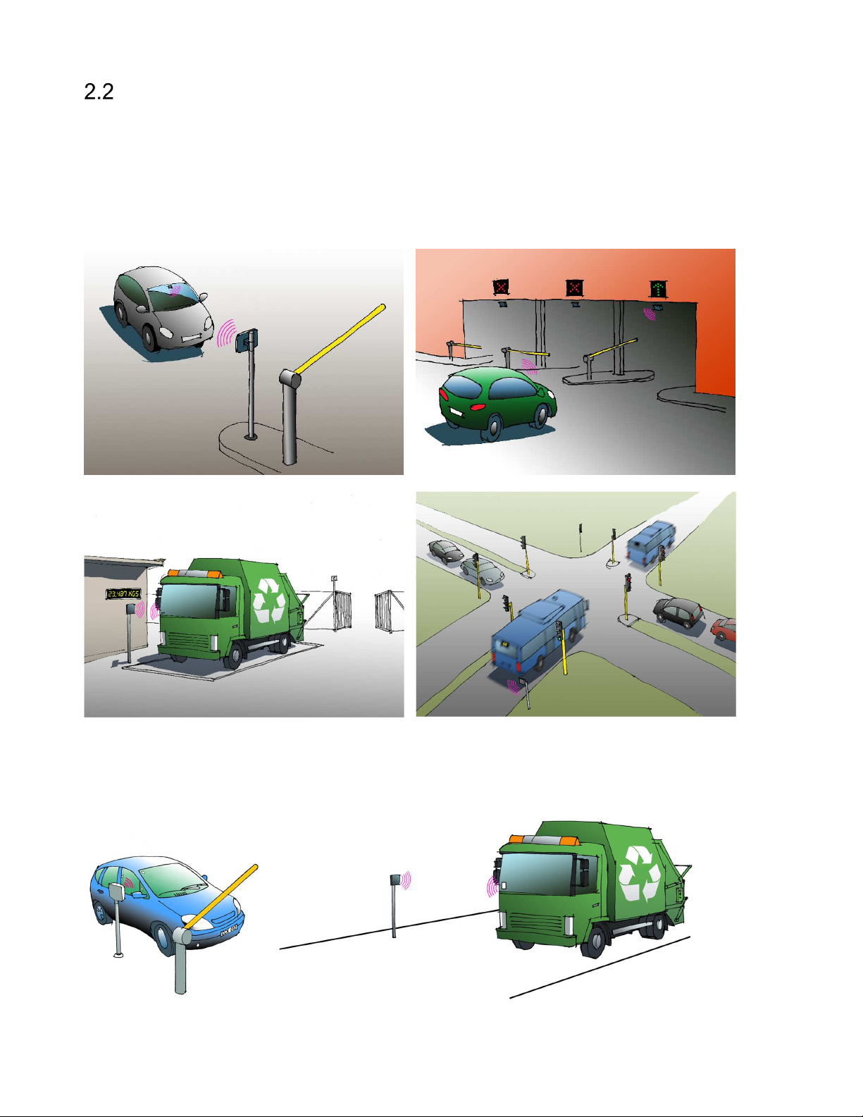
Figure 1 shows some typical installations for the XT-1, XT-5 and XT-5 ETC readers:
A. Single lane parking entrance. The reader is directed to read windshield or headlight tags.
B. Multilane parking entrance. To minimize the risk for cross reads, the readers/antennas are mounted
above the cars and the cars are equipped with windshield or headlight tags.
C. Access control (at the gate) and vehicle identification (at the weighbridge). The trucks are equipped
with ISO card tags that are mounted in a holder on the windshield and read from the side.
D. Traffic control. Readers are used to enable a green wave for buses.
A
C
Figure 1 XT-1 installations
Figure 2 shows two installations with side-mounted readers.
A. XT Mini is optimal for parking access with moderate read range requirements.
B. A side-mounted XT-1 or XT-5 covers a wide road.
B
D
A B
Figure 2 Side-mounted reader (A: XT Mini, B: XT-1/XT-5)
Page 6 of 36
Page 7
13-111 P11D, 2017-10-03 XT Series Reader Manual
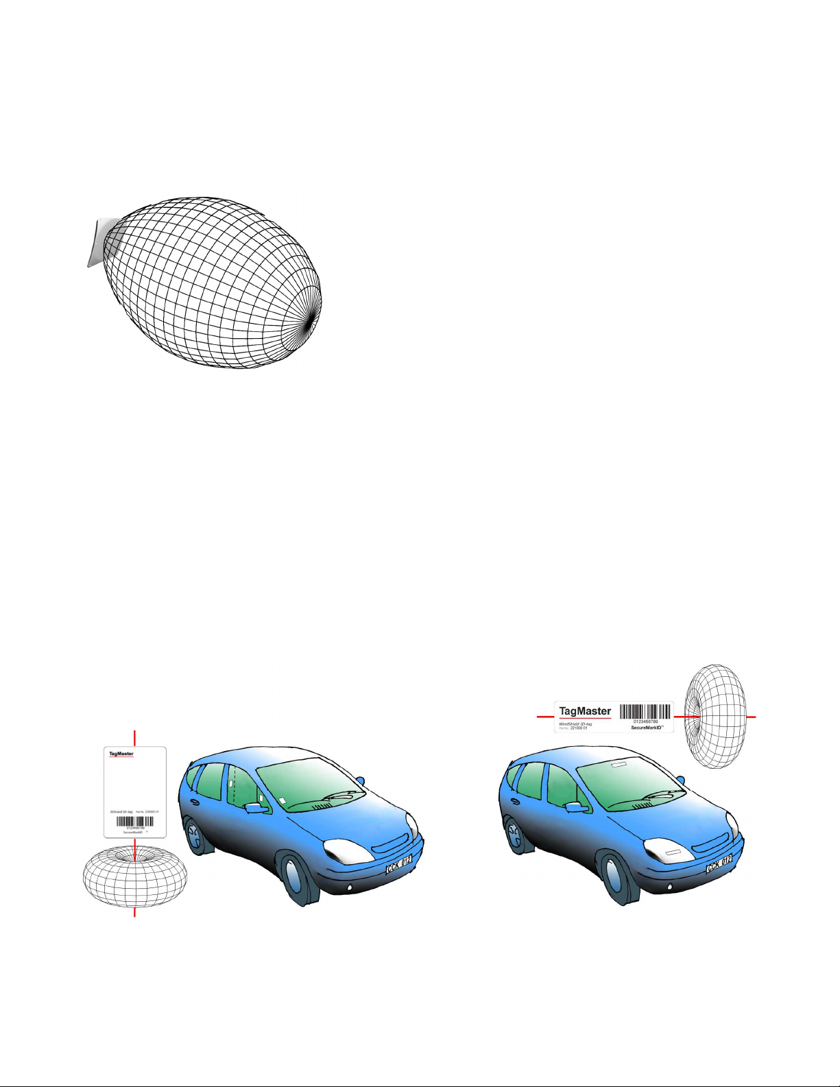
The reader's radiation pattern or read lobe (the region where the reader can read tags) is shaped like a
balloon in front of the reader as shown in Figure 3. The maximum read range is obtained when the tag is at
the tip of the balloon. At or close to this point, the width of the balloon is very small, which means that the
tag has to be accurately positioned to be read. It is recommended to mount the reader such that the tag
can be read at the widest part of the balloon which is at around 60-70% of maximum read range. If
required, the maximum read range can be reduced as described in section 4.3.1.
The reader should be mounted such that there is free sight
between the reader and the tag. Radio waves from the reader
cannot pass through metal or objects containing water (such as
humans). Metallic objects close to the reader may cause
reflections that can significantly reduce the read range.
Different tags have different mounting requirements. ISO card tags
are generally optimized for free air and - if used in a car - should
be mounted in a card holder that creates an air gap between the
tag and the windshield. Windshield tags must be mounted on the
windshield for optimal performance. Typical tags do not work if
Figure 3 Reader radiation pattern
they are mounted on metal or objects containing water. Metallized
windshields may prevent tag reading as they block radio waves.
Most RAIN RFID tags have a donut shaped radiation pattern as shown in Figure 4. This means that the
tags can be read not only when the front side is facing the reader, but also when the backside or long
edges are facing the reader. If the tag is turned such that one of the short edges is facing the reader, the
read range drops rapidly.
If the reader is mounted beside the car, the tag should be mounted with the donut lying as shown in the left
part of Figure 4. Note that the tag can be mounted in the windshield and read when the long edge of the tag
is facing the reader. If the windshield is metallized, the tag can be mounted in the side window or on the
front of the B-pillar (with a suitable holder creating a distance from the metal). A side-mounted reader
together with a tag with a lying donut can be used to cover a wide road as shown in Figure 2 B.
If the reader is mounted above or in front of the car, the tag should be mounted with the donut standing as
shown in the right part of Figure 4. In a multilane installation (Figure 1 B) it is recommended to mount the
tags like this with the reader above the car to reduce the risk of cross reads. If the windshield is metallized,
a transparent tag can be mounted on the headlight.
Figure 4 Tag radiation patterns and example placement
Page 7 of 36
Page 8
XT Series Reader Manual 13-111 P11D, 2017-10-03
Mounting Instructions
Mount the reader in a horizontal position with the cable glands down. Study the installation examples and
radiation patterns in section 2.2 to determine the optimal placement of readers and tags in your installation.
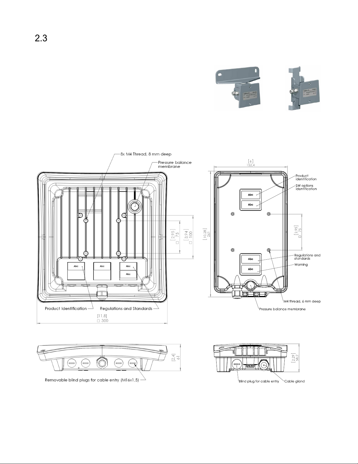
2.3.1 Universal Mounting Kit (UMK)
The UMK (TagMaster part. no. 193600) makes it easy to mount
the reader in a wide variety of positions and angles. The kit
contains all parts needed to mount the reader on a wall or a
pole. The kit is designed and suitable for outdoor use. See
separate datasheet [1] for more details in on installation.
2.3.2 Dimensions
Reader dimensions are shown in Figure 6 (XT-1/XT-5/XT-5 ETC to the left, XT Mini to the right).
Figure 5 Universal Mounting Kit (UMK)
Figure 6 Reader Dimensions in [inch] and mm
Page 8 of 36
Page 9
13-111 P11D, 2017-10-03 XT Series Reader Manual
Cable Connections
2.4.1 XT Mini
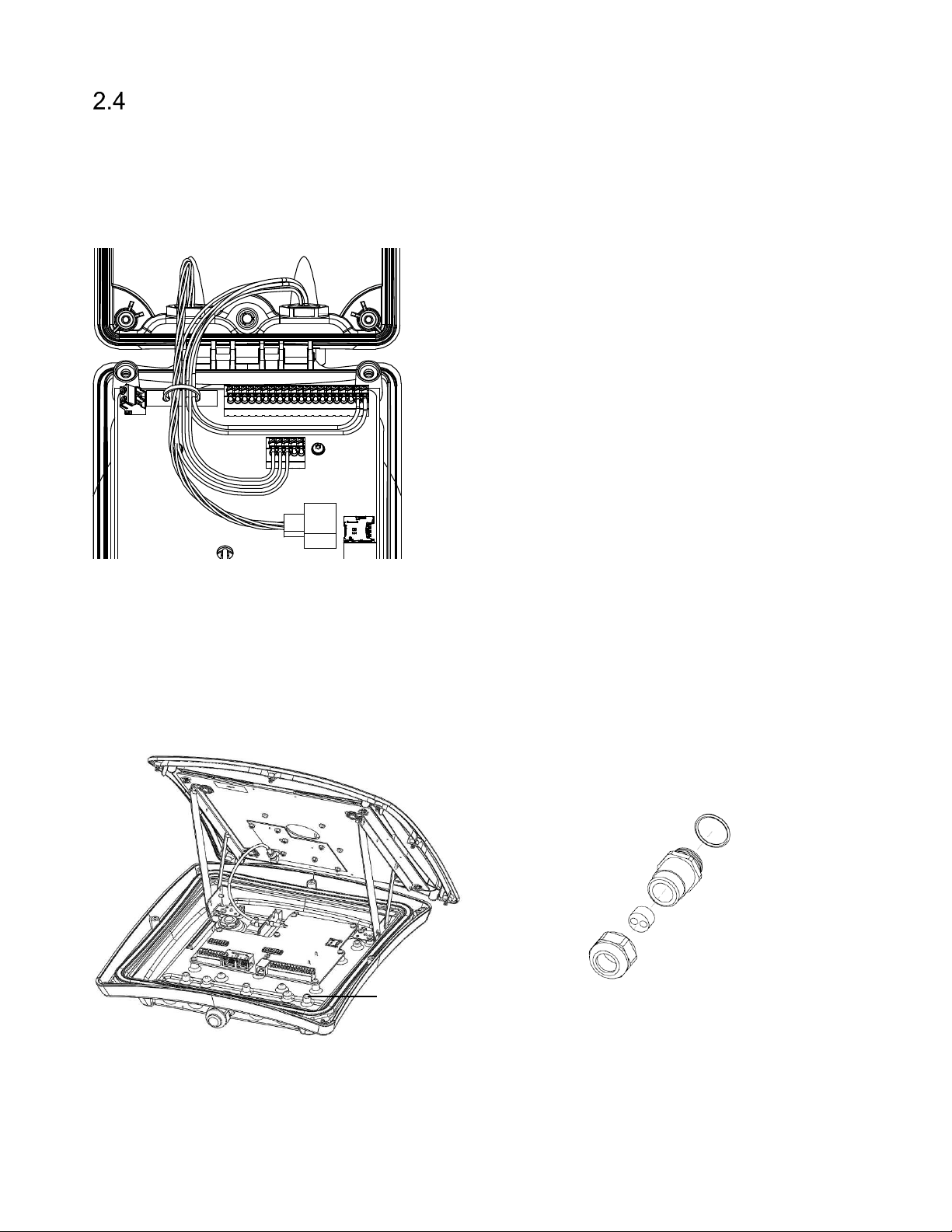
In XT Mini, cables should be connected through the two M16 cable glands. A cable tie should be used to
guide the wires when the lid is closed. Make sure to use cables with flexible wires. It is recommended to
use the left cable gland for Ethernet connections and the right cable gland for other connections. An
example with power, Ethernet and RS485 connections is shown in Figure 7.
Figure 7 XT Mini with power, Ethernet and RS485 connections
2.4.2 XT-1
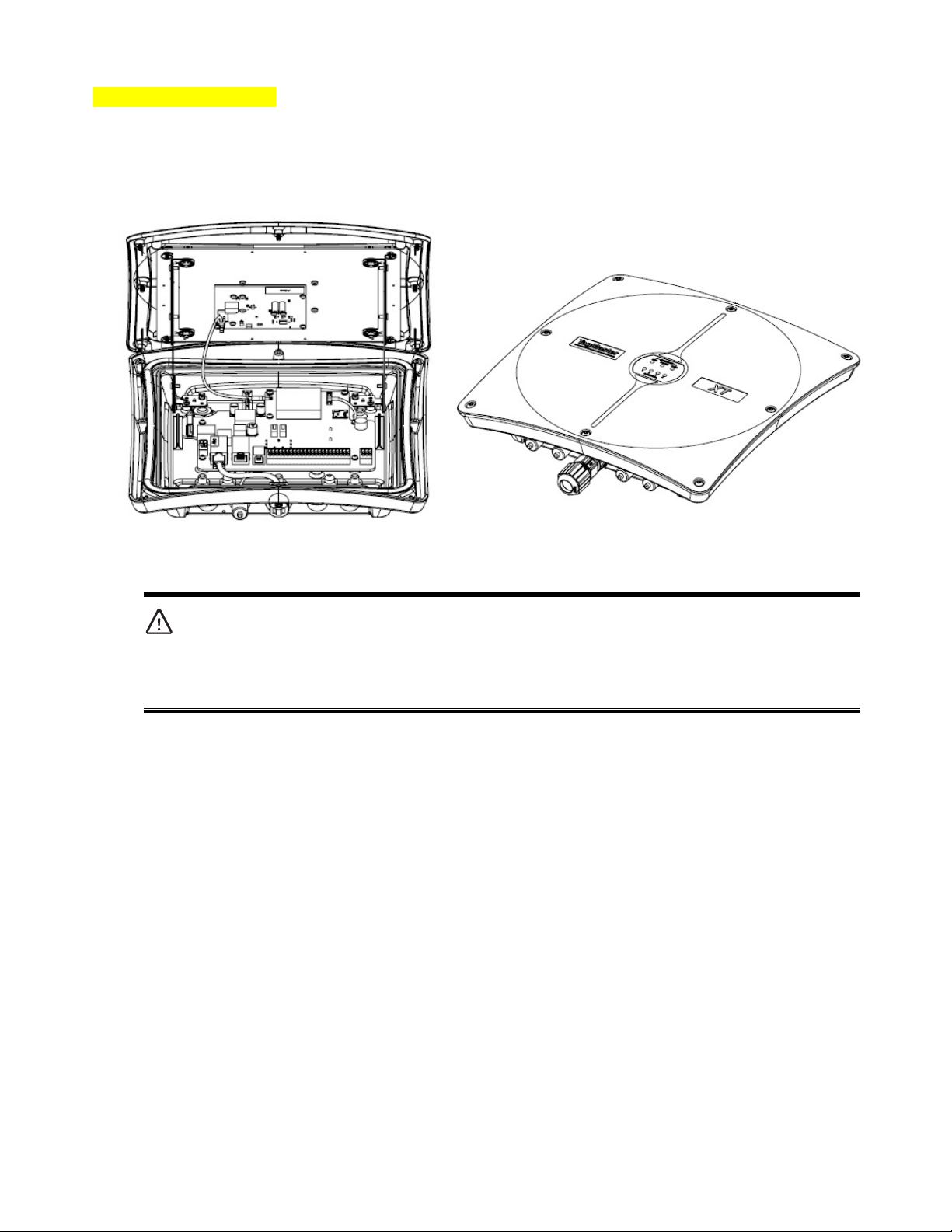
In XT-1, cables should primarily be connected through the central M20 cable gland. This cable gland can
be used with one cable (Ø 6-12 mm) or two cables (Ø 2-6 mm) using the supplied insert. As an alternative,
one or more of the four M16 blind plugs can be replaced with cable glands. Use shielded flexible cables
with stranded wire. Ground the reader chassis using the grounding screw.
Grounding screw
Figure 8 XT-1 with open lid (left), cable gland with insert for two cables (right)
Page 9 of 36
Page 10
XT Series Reader Manual 13-111 P11D, 2017-10-03
2.4.3 XT-5 / XT-5 ETC
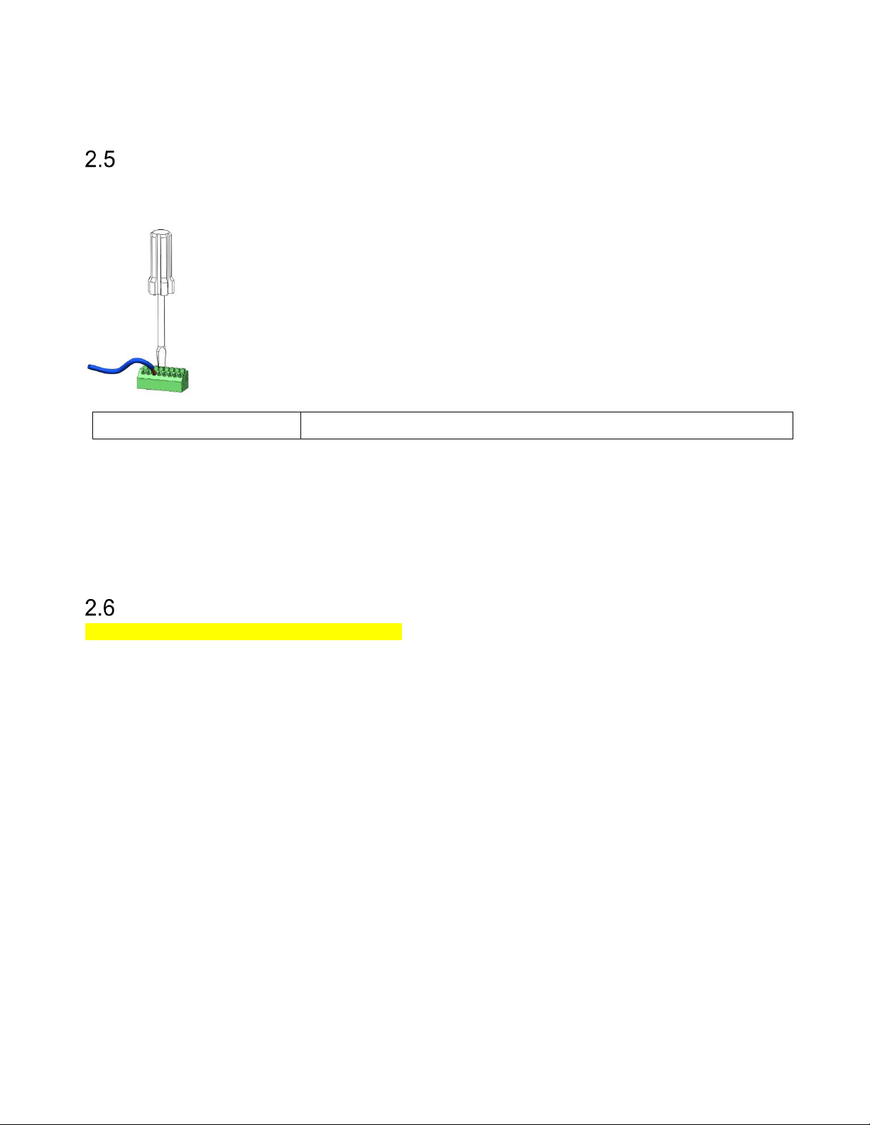
With XT-5 and XT-5 ETC, Ethernet and power (PoE+) should normally be connected to the external RJ45
connector. On XT-5, the three M16 blind plugs can be replaced with cable glands if more connections are
needed. On XT-5 ETC, the external RJ45 connector can be replaced by a M20 cable gland for one or more
cables (the same type of cable gland that is used for XT-1).
Figure 9 XT-5 with lid open (left) and XT-5 ETC with lid closed (right).
Important!
This device complies with part 15 of the FCC Rules. Operation is subject to the following two
conditions: (1) This device may not cause harmful interference, and, (2) This device must accept
any interference received including interference that may cause undesired operation.
Page 10 of 36
Page 11
13-111 P11D, 2017-10-03 XT Series Reader Manual
Wire Connections
2.5.1 Spring Cage Terminals
With the exception of Ethernet and USB, all wires are connected to spring cage terminals.
These terminals are easy to use and work with both solid and stranded wires.
Instructions
1. Strip wire lead approximately 9 mm.
2. Push screwdriver down to release spring cage.
3. Insert wire into terminal.
4. Remove screwdriver to clamp wire.
5. Gently pull installed wire to make sure connection is reliable.
Wire size 0.5 mm2 - 1.5 mm2 (AWG 20 - AWG 16)
Table 1 Wire connection overview
2.5.2 Ethernet and USB
Ethernet connections are made with standard RJ45 connectors. In XT-5 and XT-5 ETC, the first Ethernet
port is available externally. For XT Mini, XT-1 and the second Ethernet port in XT-5 and XT-5 ETC, make
sure to pass the Ethernet cable through the cable gland before crimping the connector to the cable.
USB connections are made with standard type A and B connectors.
External Antennas
ADD INFORMATION FOR XT-5 AND XT-5 ETC!
Page 11 of 36
Page 12
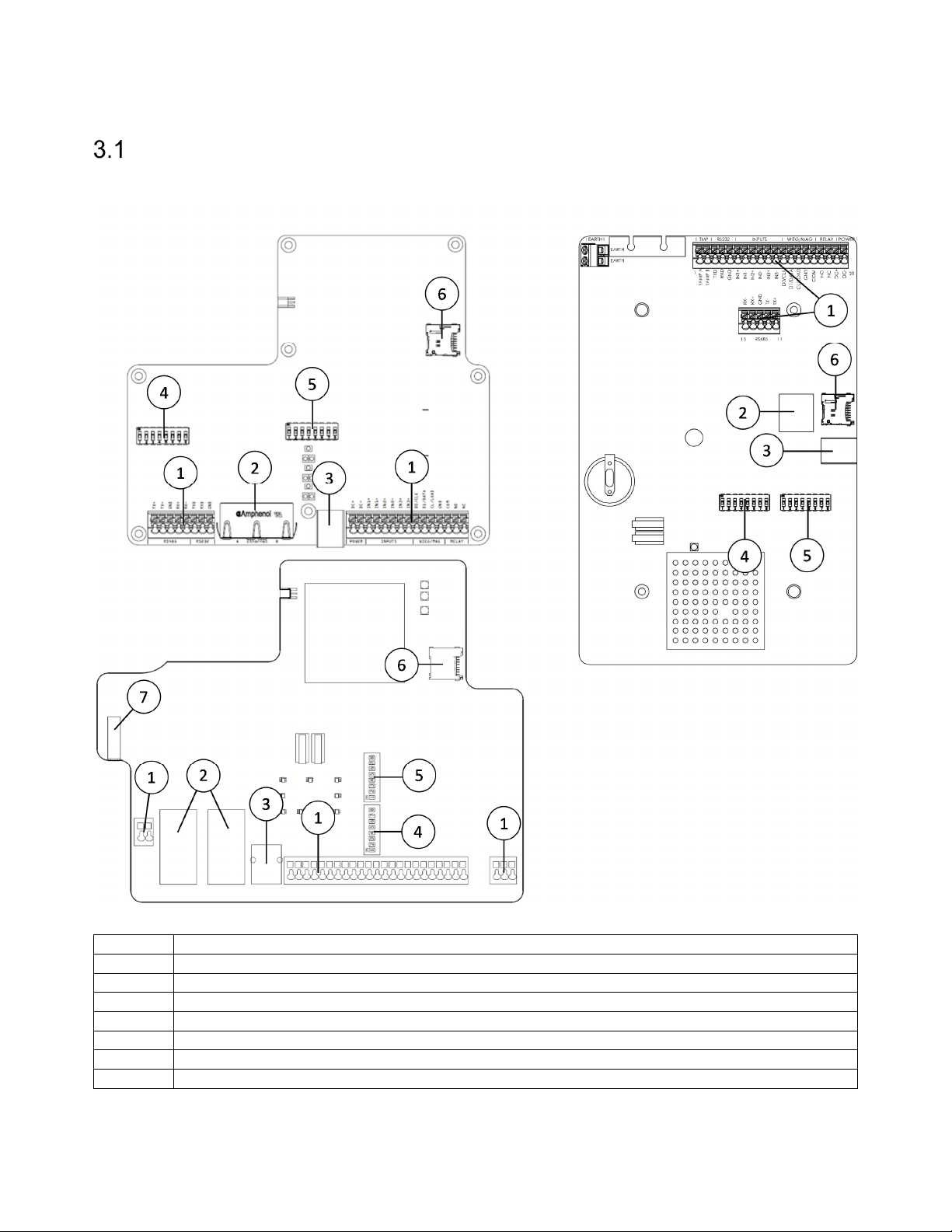
XT Series Reader Manual 13-111 P11D, 2017-10-03
Position
Interface(s)
2 ETHERNET
(with PoE+ on XT
-
5 and
XT-5 ETC
)
3 USB
DEV
4 DIP S301/
IF_DIP
5 DIP S101/
SW_DIP
6 MICROSD
7 USB HOST (XT
-
5 and
XT-5 ETC
)
3 Interfaces
Overview
Figure 10 shows the locations of all interfaces in the different reader models. The name of each interface is
listed in Table 2. The following sections refer to the interfaces as named in the table.
Figure 10 XT-1 (top left), XT-5/XT-5 ETC (bottom left), and XT Mini (right) interface locations
1 POWER, RS232, RS485, INPUTS, WIEG/MAG, RELAY, TAMPER (all models except XT-1)
Table 2 Interface names
Page 12 of 36
Page 13
13-111 P11D, 2017-10-03 XT Series Reader Manual
POWER:DC+
High supply potential
POWER:
12-24 VDC
High supply potential
XT Mini
ETHERNET:A
Ethernet port
ETHERNET:A
Ethernet port
ETHERNET:B
Ethernet port
ETH B
Ethernet port
ETH_A/PoE+
Ethernet/PoE+ port (external RJ45)
ETH B (internal)
Ethernet port
Power Supply
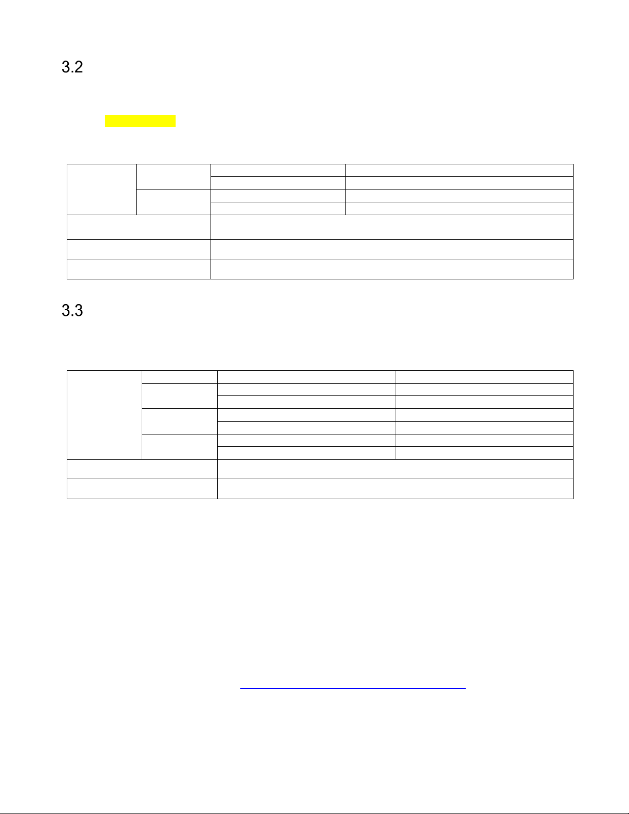
XT Mini and XT-1 have a single 12-24 VDC power supply input. XT-5 and XT-5 ETC can be powered either
from 12-24 VDC or Power-over-Ethernet (PoE+, IEEE 802.3at). When using the power supply input, the
readers shall be powered from an isolated power supply. It is recommended to use a power supply of
24 VDC, 0.5 A minimum.
The power supply input has built-in reverse polarity protection.
XT-1,
Connections
Supply voltage
Max cable length 100 m
Wire size Recommended 1.5 mm2 (AWG 16)
Table 3 Power connection overview
XT Mini
XT-5, XT-5
ETC
POWER:DC− Low supply potential (ground)
POWER:0 VDC Low supply potential (ground)
12 VDC to 24 VDC
(Absolute minimum rating 10 VDC, absolute maximum rating 30 VDC)
Ethernet
The reader has a 10 Mbps/100 Mbps Ethernet interface with one or two ports. The interface supports auto
crossover (Auto-MDIX) so that installation can be done using either patch cables or crossover cables. In XT-5
and XT-5 ETC one of the ports supports Power over Ethernet (PoE+, IEEE 802.3at).
XT-1
Connections
Max cable length 100 m
Wire size CAT5e cable or better is required for the Ethernet connection
Table 4 Ethernet connection overview
All IP settings can be changed under Settings…/Interfaces…/Ethernet in the web interface. A reboot is
required to activate new settings.
For XT Mini and XT-1, the reader's default IP address and subnet mask can be found on a label on the
backside of the reader. The default address is on the format 10.x.x.x and the subnet mask is 255.0.0.0.
The XT-5 and XT-5 ETC readers are by default configured to get IP settings from a DHCP server. If no
DHCP server is available, these readers will auto-assign an IP address in the range 169.254.x.x/16.
For convenience, it is possible to force the reader to use a fixed IP address by setting SW_DIP/S101:3 to
ON before starting the reader. The IP address will then be 169.254.1.1 and the subnet mask 255.255.0.0. A
PC that is directly connected to a reader will usually get an IP address in this subnet automatically.
A reader discovery tool is available at ftp://partner:[email protected]/Vigilant. This tool can find
readers on a local network even if their IP settings are completely incorrect. The readers can then be
restored to factory defaults and their IP settings can be configured. XT-5 and XT-5 ETC also support UPnP
and Bonjour (mDNS/DNS-SD). These protocols make the readers visible under Network in Windows
Explorer and under Bonjour in Apple Safari.
XT-5
XT-5 ETC
ETH A/PoE+ Ethernet/PoE+ port (external RJ45)
Page 13 of 36
Page 14
XT Series Reader Manual 13-111 P11D, 2017-10-03
WIEG:D0
Wiegand 0
WIEG:D1
Wiegand 1
WIEG:CL
Card load
WIEG:GND
Signal ground #1
WIEG:D1 A
Interface A, Wiegand 1
WIEG:D1 B
Interface B, Wiegand 1
MAG:CLK
Magstripe clock
MAG:DATA
Magstripe data
MAG:LOAD
Card load
MAG:CK A
Interface A, Magstripe clock
MAG:GND
Signal ground #1
Interface A, Card load
(IF_DIP:7 ON)
MAG:DT B
Interface B, Magstripe data
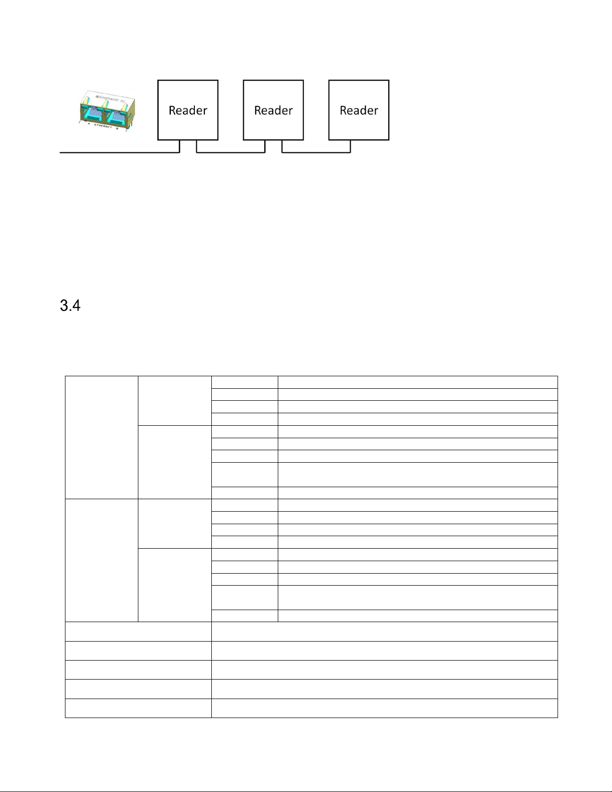
XT-1, XT-5 and XT-5 ETC have a built-in two-port Ethernet switch which enables chaining of readers.
Figure 11 Readers connected in a chain using the built-in Ethernet switch
The readers support ICMP echo request/reply (ping) to simplify network troubleshooting. By default,
ping beep is enabled which means that the reader beeps when it receives a ping packet. Ping beep can be
used to identify which reader that has a specific IP address or to determine if ping packets get lost on the
way to the reader or from the reader. Ping beep can be disabled using the web interface.
The reader can work as a TCP server and/or TCP client. As a client, the reader automatically connects to a
specified TCP server when it has data to send. The IP address and port of the server and the protocol to
use can be configured under Settings…/Interfaces…/Ethernet in the web interface. Supported protocols are
Push and TAGP. As a TCP server, the reader supports several protocols, including TAGP.
Wiegand/Magstripe
The readers have one or two Wiegand/Magstripe interfaces. XT Mini and XT-1 have one interface. XT-5 and
XT-5 ETC have two interfaces (A and B) that can be configured as a single interface using IF_DIP:7 if a card
load signal is needed. With dual interfaces, tag reads from different antennas are sent to different interfaces.
Tag reads from antenna 1 (the internal antenna in XT-5) are sent to interface A.
XT Mini,
XT-1
Connections
WIEG:D0 A Interface A, Wiegand 0
(Wiegand)
XT-5, XT-5
ETC
WIEG:GND Signal ground #1
WIEG:D0 B Interface B, Wiegand 0 (IF_DIP:7 OFF)
Interface A, Card load (IF_DIP:7 ON)
XT Mini,
XT-1
MAG:GND Signal ground #1
Connections
(Magstripe)
MAG:DT A Interface A, Magstripe data
XT-5, XT-5
ETC
MAG:CK B Interface B, Magstripe clock (IF_DIP:7 OFF)
Max cable length 100 m (depending on properties of receiving system)
Wire size 0.5 mm2 (AWG 20), 1.5 mm2 (AWG 16) above 10 m of length.
Voltage Typ 5 V / Max 30 V
Sink current Max 500 mA
Isolation Min 1500 VDC
Table 5 Wiegand connection overview
Page 14 of 36
Page 15
13-111 P11D, 2017-10-03 XT Series Reader Manual
Output Format
Description
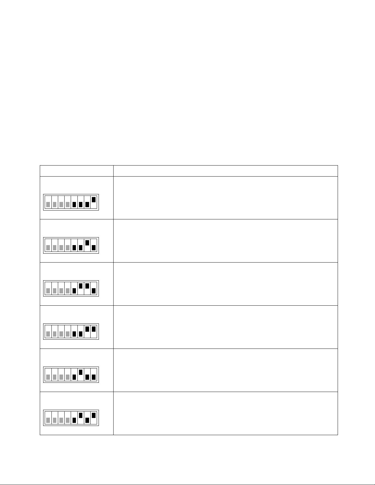
The Wiegand/Magstripe signals can be internally pulled up to 5 V with 1 kΩ resistors. Pull-ups are activated
using DIP switches S301:6-8 on XT Mini and XT-1 and IF_DIP:6 on XT-5 and XT-5 ETC.
All Wiegand/Magstripe settings are available under Settings…/Interfaces…/Wieg/Mag in the web interface.
It is possible to select a predefined format or define a custom format.
The most common predefined formats can be selected by setting SW_DIP/S101:5-8 as shown in the table
below. When any of these switches are in the ON position, the reader is also configured to report tags once
and only accept SecureMarkID tags.
The following formats can be selected by DIP switches:
D = Data from tag (bit for Wiegand/digit for Magstripe)
S = Value of Site code
E = Even parity bit, O = Odd parity bit, X = Bit included in parity calculation
B = Magstripe start character, F = Magstripe stop character, L = Magstripe LRC
W26S/H10301
SW_DIP/S101
1 8
W26N/H10301
SW_DIP/S101
1 8
W34N
SW_DIP/S101
1 8
W37N/H10302
SW_DIP/S101
1 8
W37R/H10302
SW_DIP/S101
26-bit Wiegand (8-bit site code, 16-bit data):
ESSSSSSSSDDDDDDDDDDDDDDDDO
ON
XXXXXXXXXXXXX-------------
-------------XXXXXXXXXXXXX
26-bit Wiegand (24-bit data, no site code):
EDDDDDDDDDDDDDDDDDDDDDDDDO
ON
XXXXXXXXXXXXX-------------
-------------XXXXXXXXXXXXX
34-bit Wiegand (32-bit data, no site code):
EDDDDDDDDDDDDDDDDDDDDDDDDDDDDDDDDO
ON
XXXXXXXXXXXXXXXXX-----------------
-----------------XXXXXXXXXXXXXXXXX
37-bit Wiegand (35-bit data, no site code):
EDDDDDDDDDDDDDDDDDDDDDDDDDDDDDDDDDDDO
ON
XXXXXXXXXXXXXXXXXXX------------------
------------------XXXXXXXXXXXXXXXXXXX
37-bit Wiegand (37-bit data, no site code, no parity):
DDDDDDDDDDDDDDDDDDDDDDDDDDDDDDDDDDDDD
ON
Table 6 Wiegand/Magstripe formats
1 8
M8N/H10320
SW_DIP/S101
1 8
8-digit Magstripe:
[25 zeroes]BDDDDDDDDFL[165 zeroes]
ON
Page 15 of 36
Page 16
XT Series Reader Manual 13-111 P11D, 2017-10-03
µ
µ
tPI
Pulse interval
2 ms
µ
µ
tF
Fall time (all signals)
125 ns
µ
µ
µ
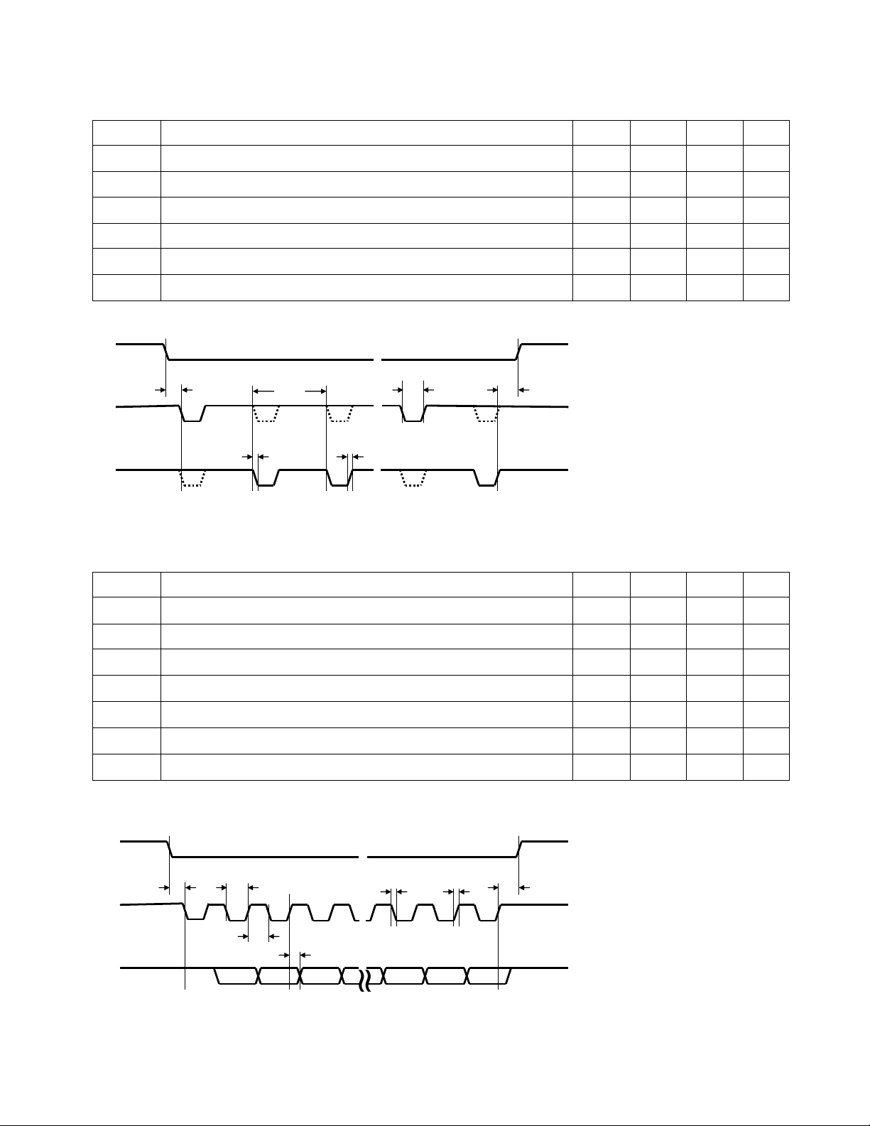
3.4.1 Wiegand Timing
The following values apply when all outputs are pulled up to 5 V with 1 kΩ resistors.
Symbol
Parameter Min Typ Max Unit
tSU CL to D# setup time 1520
tF Fall time (all signals) 125 ns
tR Rise time (all signals) 5
tPW Pulse width 80
tH CL hold time after last D# change 1840
Table 7 Wiegand interface timing
t
R
≈ ≈ ≈
t
PW
t
H
CL
t
SU
D0
D1
t
PI
t
F
Figure 12 Wiegand timing diagram
3.4.2 Magstripe Timing
The following values apply when all outputs are pulled up to 5 V with 1 kΩ resistors.
Symbol
Parameter Min Typ Max Unit
s
s
µ
s
s
tSU LOAD to CLK setup time 1520
tR Rise time (all signals) 5
tCL Clock low 480
tCH Clock high 960
tH LOAD hold time after last CLK change 1520
tDH Data hold time 880
Table 8 Magstripe interface timing
LOAD
CLK
t
SU
t
CL
t
CH
t
DH
≈
≈
t
t
F
R
t
H
≈
DATA
Figure 13 Magstripe timing diagram (note: data low = logic one)
s
s
s
s
µ
s
µ
s
Page 16 of 36
Page 17
13-111 P11D, 2017-10-03 XT Series Reader Manual
Off - No link detected
Off - 10 Mbit/s
Off - Antenna inactive/not
present (CARRIER = OFF)
RS232:TXD
Transmitted data to host
RS232:RXD
Received data from host
RX232:GND
Signal g
round
#2
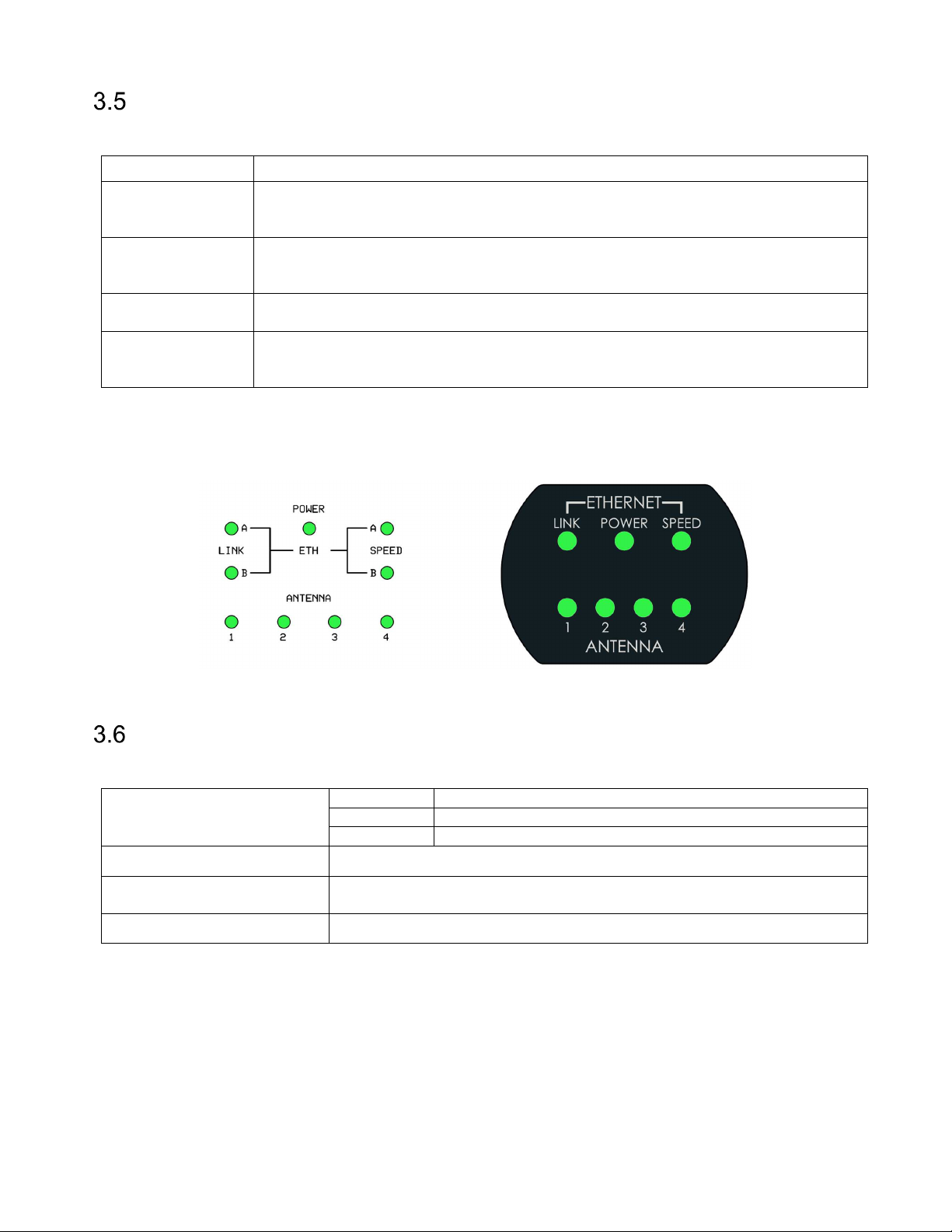
Status Indicators
The readers have status indicators that are visible on the controller board and on the XT-5 ETC lid.
Indicator Description
POWER Flashing - Reader is powered and firmware is running
On - Reader is powered but the firmware is not running
Off - Reader is now powered
ETH LINK A/B Flashing - Activity
On - Link detected
ETH SPEED A/B On - 100 Mbit/s
ANTENNA 1-4
(XT-5, XT-5 ETC)
The status indicators on XT-5 and XT-5 ETC are shown in Figure 14. In XT Mini and XT-1, the POWER
indicator is a single green LED and the Ethernet indicators, ETH LINK and ETH SPEED, are yellow and
green LEDs mounted on or close to the Ethernet port(s).
Figure 14 Status indicators on XT-5/XT-5 ETC controller board and XT-5 ETC lid
Flashing - Reading tags
On - Antenna active (CARRIER = ON)
RS232
The RS232 interface can be used for communication with a host system.
Connections
Max cable length 10 m
Wire size
Max Baud rate 115.2 kb/s (default)
Table 9 RS232 connection overview
The default output of the RS232 interface is tag data in ASCII format. If SecureMarkID® tags from
TagMaster are being used (recommended) the numeric identity is sent out. If other EPC tags are being
used the default output is the EPC data. The data is followed by CR+LF ("\r\n").
A TAGP connection can be initiated by sending the HELOTAGP message to the reader. The TAGP
connection is terminated with the QUIT message. Other protocols can be enabled using the web interface.
These protocols are described in separate manuals.
All RS232 settings are available under Settings…/Interfaces…/RS232 in the web interface.
Specification according to EIA RS232C. Belden 9184 or Belden 9502 are
recommended.
Page 17 of 36
Page 18
XT Series Reader Manual 13-111 P11D, 2017-10-03
RS485:TX+
Transmitted data to host
RS485:TX
- Transmitted data to host
RS485:GND
Signal g
round
#3
RS485:RX
- Received data from host
RS485
The RS485 interface can be used for communication with a host system.
Connections
RS485:RX+ Received data from host
Max cable length 1000 m
Wire size
Max Baud Rate 115.2 kb/s (default)
Table 10 RS485 connection overview
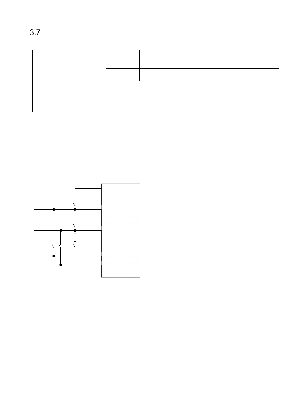
The hardware supports 2-wire (IF_DIP/S301:1-2 ON) and 4-wire communication, half duplex and full duplex
as well as multi-drop. When using RS485 communication, correct termination of the interface should be
considered in order to handle transmission-line effects. The readers have a built-in option (IF_DIP/S301:3
ON) of 120 Ω termination on the receive side (to be used at each end of the RS485 chain), and an option
(IF_DIP/S301:4-5 ON) of 620 Ω bias on the receive side (to be used at one node in the RS485 chain). The
options using DIP switches are detailed in Figure 15 and also described in section 3.15.
With factory default settings, the reader should always be configured in 4-wire mode (IF_DIP/S301:1-2
OFF) since the TAGP protocol requires a full-duplex link. Other protocols require different settings.
The cable for the RS485 interface must be a twisted pair cable and
conform to the EIA RS485 standard.
5V iso
620 Ω
IF_DIP/
IF_DIP/
S301:1
IF_DIP/
S301:2
S301:4
120 Ω
IF_DIP/
S301:3
620 Ω
IF_DIP/
S301:5
RX+
RX-
TX+
TX-
RS485
driver
Figure 15 RS485 DIP switch configuration
The default output of the RS485 interface is tag data in ASCII format. If SecureMarkID® tags from
TagMaster are being used (recommended) the numeric identity is sent out. If other EPC tags are being
used the default output is the EPC data. The data is followed by CR+LF ("\r\n").
A TAGP connection can be initiated by sending the HELOTAGP message to the reader. The TAGP
connection is terminated with the QUIT message. Other protocols can be enabled using the web interface.
These protocols are described in separate manuals.
All RS485 settings are available under Settings…/Interfaces…/RS485 in the web interface.
Page 18 of 36
Page 19
13-111 P11D, 2017-10-03 XT Series Reader Manual
INPUTS:IN1+
Input 1 positive
terminal
INPUTS:IN1
− Input 1 negative terminal
INPUTS:IN2+
Input 2 positive terminal
INPUTS:IN3+
Input 3 positive terminal
INPUTS:IN4+
Input 4
positive terminal
INPUTS:IN4
− Input 4 negative terminal
Inputs
The reader has three (XT-1 and XT Mini) or four (XT-5 and XT-5 ETC) opto-coupled inputs.
All models
Connections
XT-5, XT-5
ETC
High Voltage (active) Min 3.0 V / Max 30 V
Low Voltage (inactive) Min 0.0 V / Max 0.2 V
Input impedance 1 kΩ
Max cable length 100 m
Wire size 0.5 mm2 (AWG 20)
Table 11 Input connection overview
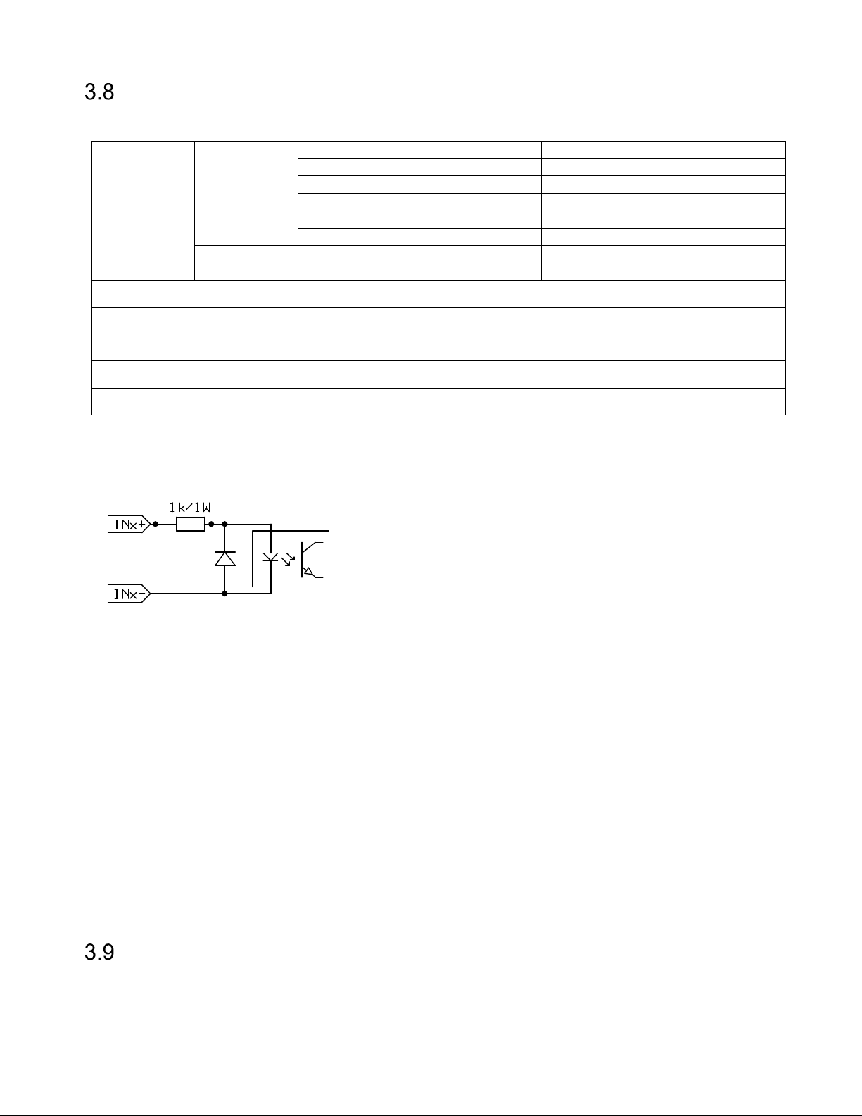
The inputs are activated by a current flow and the input impedance is 1 kΩ. A schematic view of an input is
shown in Figure 16.
INPUTS:IN2− Input 2 negative terminal
INPUTS:IN3− Input 3 negative terminal
Figure 16 Input schematic
The first two inputs can be used to control the green and red LED from an external access control system
to indicate if access has been granted or denied. The third input can be used as a read enable/disable
input. This input can be connected to an external presence detector such as an inductive loop to make sure
that the reader only reads tags when a vehicle is present.
All inputs have a debounce filter that is enabled by default. When the debounce filter is enabled, short
pulses on the inputs are ignored. Pulses must be at least 20 ms to guarantee that they are detected. The
polarity of the inputs can be inverted to cope with signals that are active high or active low.
The read enable/disable input can be configured to work in different modes. "Read time" is used to specify
how long time reading should be enabled after it has been activated by the input. If read time is zero,
reading is enabled as long as the input is active. The "Abort after read" setting can be used to abort reading
after a single tag has been read (read time must be non-zero for this setting to have any effect). The
"Indicator" setting is used to specify the colour of the LED when reading is enabled.
All input settings are available under Settings…/Interfaces…/Inputs in the web interface.
Light and Sound
Reader antennas (built-in and external) have a bright multi-colour LED indicator. The LED indicator can
show when a tag has been read and if access has been granted or denied.
A built-in buzzer can give an audible indication when a tag has been read or settings have been changed.
Page 19 of 36
Page 20
XT Series Reader Manual 13-111 P11D, 2017-10-03
RELAY:COM
Common
RELAY:NC
Normally Closed
ETC
Relay
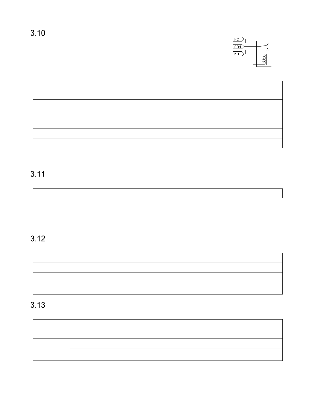
The relay output can be used to control a barrier, gate, or other object. The relay
can either be activated when any tag has been read or when an accepted tag has
been read. A tag is considered accepted when it is listed in the built-in access
controller's database. The active time can be configured.
Figure 17 Inactive relay
Connections
Switching current Max 2 A
Switch voltage Max 60 VDC / 30 VAC
Switching capacity: Max 60 W / 62,5 VA
Max cable length 100 m
Wire size 0.5 mm2 (AWG 20)
Table 12 Output connection overview
Relay settings are available under Settings…/Interfaces…/Relay in the web interface.
RELAY:NO Normally Open
MicroSD Memory Card Slot
The reader is equipped with a microSD memory card slot for additional storage.
Connections MICROSD
In XT Mini and XT-1, the microSD card is needed to use the built-in access controller and logging
functionality. Information about the currently inserted microSD card can be found under Settings…/
Interfaces…/MicroSD in the web interface. On this page it is also possible to format the microSD card.
In XT-5 and XT-5 ETC, the microSD card can be used from the Linux system.
USB Device
The readers have a USB device interface that can be used for service and maintenance.
Connections USB DEV
USB connector Type B Jack
XT Mini, XT-1 12 Mbit/s (Full Speed)
Speed
XT-5, XT-5
ETC
480 Mbit/s (Hi-Speed)
USB Host (XT-5, XT-5 ETC)
XT-5 and XT-5 ETC have a USB host interface that can be used from the Linux system.
Connections USB HOST
USB connector Type A Jack
XT Mini, XT-1 12 Mbit/s (Full Speed)
Speed
Page 20 of 36
XT-5, XT-5
480 Mbit/s (Hi-Speed)
Page 21
13-111 P11D, 2017-10-03 XT Series Reader Manual
TMP:TMP A
Tamper switch connection 1
TMP:TMP B
Tamper switch connection 2
TAMPER:TMP
A
Tamper switch connection 1
Bias should be activated at
one node in an RS485 chain.
system without built
-
in pull
-
ups.
Tamper Switch (XT Mini, XT-5, XT-5 ETC)
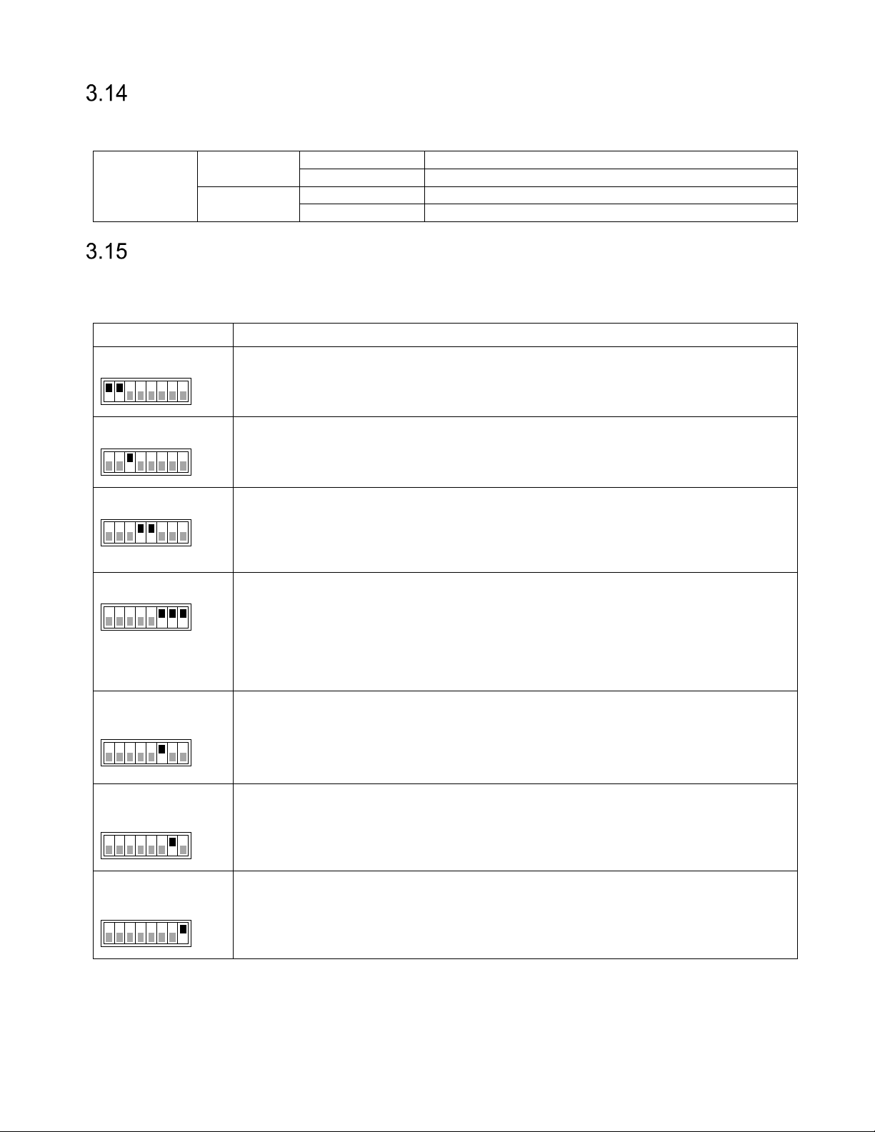
XT Mini, XT-5 and XT-5 ETC have a tamper switch that can be connected to an external alarm loop.
The circuit is opened when the lid is opened.
XT Mini
Connections
XT-5, XT-5
ETC
TAMPER:TMP B Tamper switch connection 2
DIP Switches
Two 8-position DIP switches are available for interface and software configuration.
3.15.1 Interface Configuration DIP Switch (IF_DIP/S301)
Position(s) Description
1-2
IF_DIP/S301
ON
1 8
3
IF_DIP/S301
ON
1 8
4-5
IF_DIP/S301
ON
1 8
RS485 2-wire mode
IF_DIP/S301:1 ON = TX+ connected to RX+
IF_DIP/S301:2 ON = TX– connected to RX–
RS485 termination
IF_DIP/S301:3 ON = 120 Ω termination between RX+ and RX-.
Termination should be activated at each end of an RS485 chain.
RS485 bias
IF_DIP/S301:4 ON = 620 Ω pull-up from RX+ to 5 V
IF_DIP/S301:5 ON = 620 Ω pull-down from RX- to 0 V
6-8 (XT Mini, XT-1)
S301
ON
1 8
Wiegand/Magstripe pull-ups
S301:6 ON = 1 kΩ pull-up from D0/CLK to 5 V
S301:7 ON = 1 kΩ pull-up from D1/DATA to 5 V
S301:8 ON = 1 kΩ pull-up from CL/LOAD to 5 V
Pull-ups should be activated when the reader is connected to an access control
6 (XT-5, XT-5
ETC)
IF_DIP
ON
1 8
7 (XT-5, XT-5
ETC)
IF_DIP
ON
1 8
8 (XT-5, XT-5
Wiegand/Magstripe pull-ups
IF_DIP:6 ON = 1 kΩ pull-ups to 5 V on all Wiegand/Magstripe signals
Pull-ups should be activated when the reader is connected to an access control
system without built-in pull-ups.
Wiegand/Magstripe single/dual
IF_DIP:7 ON = Single Wiegand/Magstripe interface (A) with D0/CK B = CL/LOAD
Reserved for future use
ETC)
IF_DIP
1 8
Table 13 Interface Configuration DIP Switch (IF_DIP/S301)
ON
Page 21 of 36
Page 22
XT Series Reader Manual 13-111 P11D, 2017-10-03
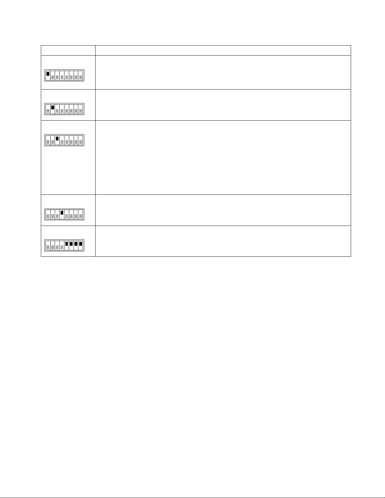
3.15.2 Software Configuration DIP Switch (SW_DIP/S101)
Position(s) Description
1
SW_DIP/S101
1 8
2
SW_DIP/S101
1 8
3
SW_DIP/S101
1 8
Firmware upgrade mode
SW_DIP/S101:1 is used for complete firmware upgrade and should normally not be
ON
used. See section 4.4 for information about normal firmware upgrade.
Factory defaults
SW_DIP/S101:2 is used to restore the reader to factory default settings.
ON
See section 4.5 for more information.
Fixed IP address
SW_DIP/S101:3 forces the reader to use the following IP settings:
ON
IP address: 169.254.1.1
Netmask: 255.255.0.0
A Windows PC that is directly connected to a reader is normally automatically
assigned an IP address in the 169.254.x.x range. This means that it is possible to
connect to a reader without changing IP settings on the PC. It may be necessary to
run "ipconfig /release" if the PC has received IP settings over DHCP.
4
SW_DIP/S101
1 8
5-8
SW_DIP/S101
1 8
Table 14 Software Configuration DIP Switch (SW_DIP/S101)
Force boot loader
SW_DIP/S101:4 forces the reader to start its boot loader at power up.
ON
See section 4.4 for more information.
Easy configuration
SW_DIP/S101:5-8 are used for easy configuration of Wiegand/Magstripe, OSDP, and
ON
other settings. See sections 5.1.1 and 5.2.1 for more information.
Page 22 of 36
Page 23
13-111 P11D, 2017-10-03 XT Series Reader Manual
4 Configuration
Web Interface
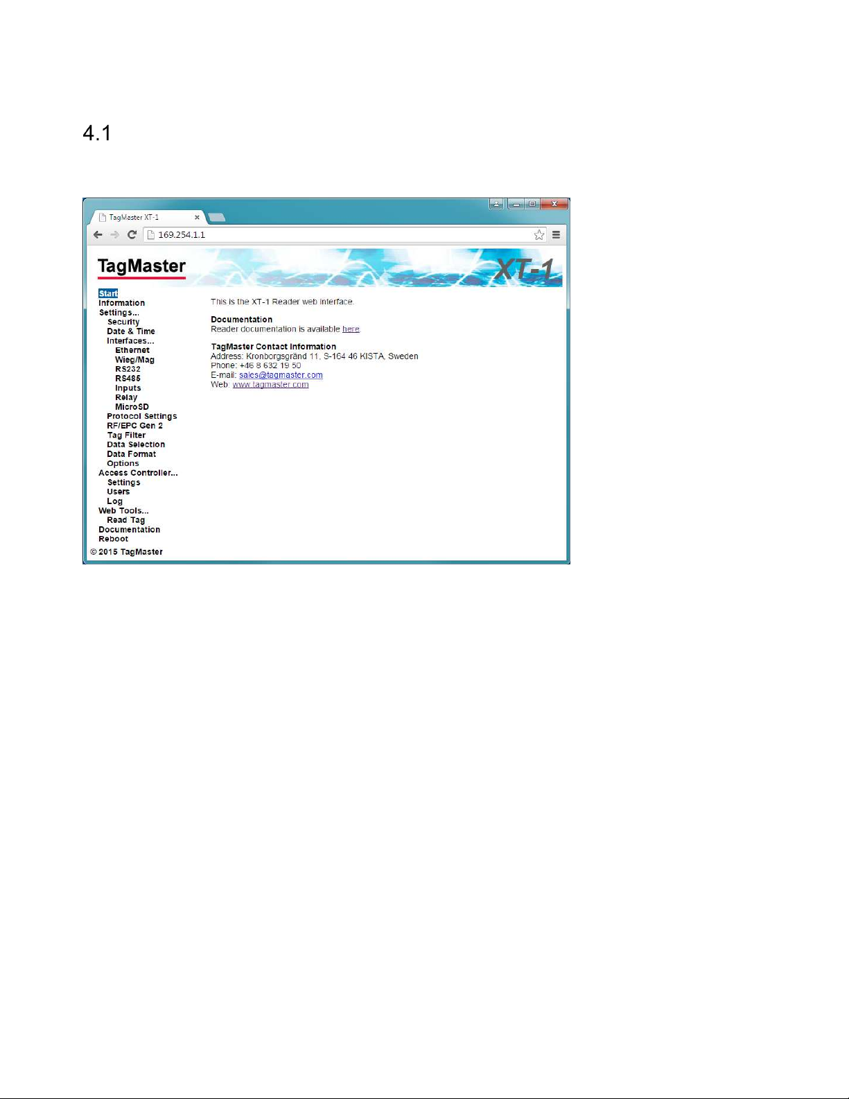
The readers have a web interface for configuration and maintenance. The web interface is designed and
tested to work with modern versions of Google Chrome and other web browsers.
Figure 18 Web interface with expanded menu
Connect to the web interface by entering the reader's IP address in the web browser's address bar.
For XT Mini and XT-1, the reader's default IP address and subnet mask can be found on a label on the
backside of the reader. The default address is on the format 10.x.x.x and the subnet mask is 255.0.0.0. The
XT-5 and XT-5 ETC readers are by default configured to get IP settings from a DHCP server. If no DHCP
server is available, these readers will auto-assign an IP address in the range 169.254.x.x/16.
For convenience it is possible to force the reader to use a fixed IP address by setting SW_DIP/S101:3 to
ON before starting the reader. The IP address will then be 169.254.1.1 and the subnet mask 255.255.0.0. A
PC that is directly connected to a reader will usually get an IP address in this subnet automatically.
If the PC does not have an IP address that is in the same subnet as the reader it is necessary to change
the PC's address. In Windows 7, this is done using "Network and Sharing Center" in "Control Panel". Click
on "Local Area Connection", "Properties", "TCP/IPv4", and "Properties". Select "Use the following IP
address" and fill in "IP address" and "Subnet mask".
Note that the web interface may look slightly different depending on the version of the firmware in the
reader. Up-to-date documentation is always available under "Documentation" in the web interface menu.
4.1.1 Start
The "Start" page provides TagMaster contact information.
4.1.2 Information
The "Information" page provides information about the system.
Page 23 of 36
Page 24
XT Series Reader Manual 13-111 P11D, 2017-10-03
4.1.3 Settings…
All configuration of the reader can be done on the "Settings…" pages. For all settings, it is possible to get
help by clicking on the question mark ( ). Click the "Save Settings" button to activate changed settings.
Click the "Factory Defaults" button to restore all settings on a page to factory defaults.
Information about important settings is available in the following sections.
4.1.4 Access Controller…
The built-in access controller is configured on the "Access Controller…" pages.
See section 6 for more information.
4.1.5 Web Tools…
The "Web Tools…" pages contain tools that are useful during installation and testing.
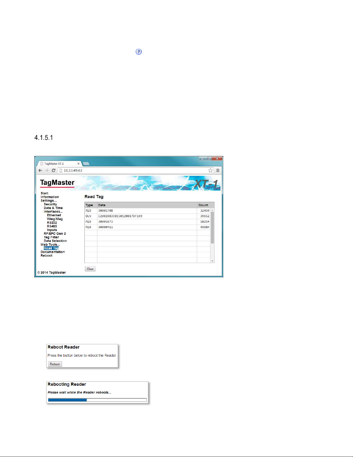
Read Tag
The "Read Tag" page makes it easy to read tags and display tag contents.
Figure 19 Read Tag
4.1.6 Documentation
The Documentation page provides up-to-date reader documentation.
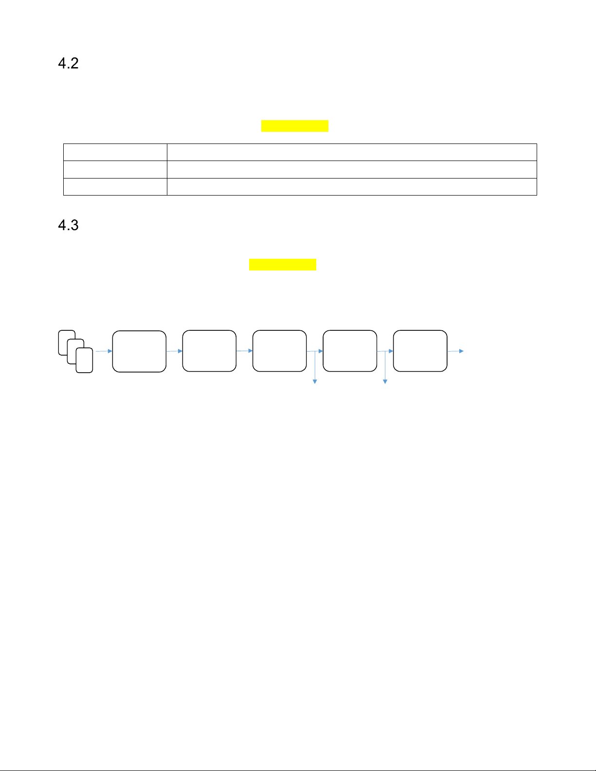
4.1.7 Reboot
The Reboot page makes it easy to reboot the reader.
• Press the "Reboot" button to initiate a reboot.
• Wait for the reboot to complete.
Page 24 of 36
Page 25
13-111 P11D, 2017-10-03 XT Series Reader Manual
Reader Version
Supported Regions
EU Europe
, India
US United States
, Australia, China,
Indonesia,
Malaysia, New Zealand
,
Thailand
Region
To meet different radio regulations around the world, the reader can be configured to work in different
regions. Each reader model comes in two versions: EU and US. Each reader version supports a number of
regions as listed in the table below. Default values are shown in bold.
The region can be changed under Settings…/RF/EPC Gen 2 in the web interface.
Table 15 Supported regions
Tag Reading
By default, the reader reads tags with maximum read range and outputs tag data in a way that is suitable
for most applications. If necessary, the tag reading process is highly configurable. Most settings controlling
tag reading are available under Settings…/RF/EPC Gen 2 in the web interface.
RAIN RFID readers manage tag populations using the three basic operations: select, inventory, and
access. The reader automatically performs all of these when the "Carrier" setting is on. The tag reading
process is show in Figure 20 and described in the following sections.
EPC
Select
EPC
Memory
Bank
Tag Filter
Data
Selection
Data
Format
Push Protocol
(RS232, RS485,
TCP Client,
Access Controller)
TAGP Other Protocols
Figure 20 Reading tags
4.3.1 Carrier and Read Level
The "Carrier" setting is used to enable/disable reading. When Carrier is on (default) the reader reads tags.
The "Read level" setting controls the read range. The default value 100 corresponds to maximum read
range.
4.3.2 EPC Select
The "EPC select" setting defines which tags the reader will talk to. Selection is done by specifying a binary
value and a part of tag memory that must match the value. Only tags that match will respond to the reader's
query. The default value "*" selects all tags.
4.3.3 EPC Memory Bank/Custom Format
The settings "EPC memory bank" and "EPC custom format" specifies which parts of the tag memory that
will be read by the reader. Available options include EPC/SecureMarkID (default), SecureMarkID, EPC, TID
and "Custom Format".
If "EPC memory bank" is set to "Custom Format" the "EPC custom format" setting specifies which parts of
the tag memory that will be read.
4.3.4 Tag Filter
The tag filter (under Settings…/Tag Filter in the web interface) specifies how often tags are reported. Tags
can be reported every time they are read, periodically or once. It is also possible to get a tag event when a
tag is no longer read by the reader. It is possible to activate read beep and read blink to get an indication
every time a tag is reported.
Page 25 of 36
Page 26
XT Series Reader Manual 13-111 P11D, 2017-10-03
The TAGP protocol reports tag events as they come out of the tag filter.
4.3.5 Data Selection
The "Data selection" settings (under Settings…/Data Selection in the web interface) specifies how the read
data shall be interpreted (binary, hexadecimal or decimal) and also makes it possible to select a part of the
data (number of digits with a left or right aligned offset).
Reader protocols with binary output reports data as it comes out of this stage.
4.3.6 Data Format
The "Data Format" settings (under Settings…/Data Format in the web interface) specifies the output format
for data that is pushed to RS232, RS485, TCP Client, and the built-in access controller.
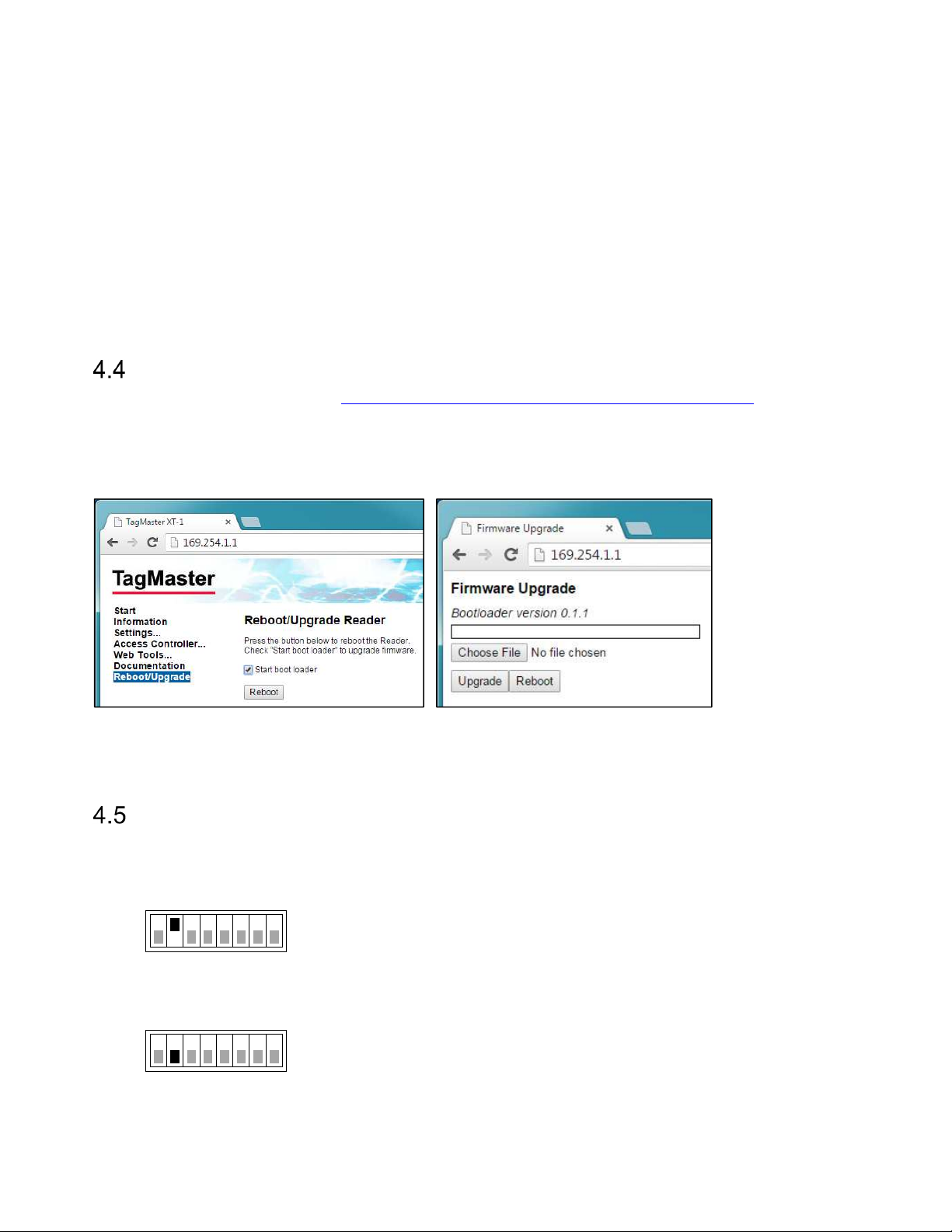
Firmware Upgrade
Download the latest firmware from ftp://partner:[email protected]/Vigilant/Firmware.
Go to the “Reboot/Upgrade” page on the web interface, check “Start boot loader” and press the “Reboot”
button to start the boot loader. In the boot loader, press “Choose File” and choose the downloaded
firmware file. Press “Upgrade” to start the upgrade and then press “Reboot” when the upgrade has finished.
Figure 21 Starting the boot loader to upgrade firmware
Note: The boot loader was added in firmware version 1.2.0. To upgrade from earlier versions, follow the
instructions in the README document that is available in the same FTP directory as the firmware.
Factory Defaults
Use the following procedure to restore the reader to factory default settings:
1. Set SW_DIP/S101:2 to ON
S101
ON
1 8
2. Power cycle the reader
3. Set SW_DIP/S101:2 back to OFF
S101
1 8
ON
Page 26 of 36
Page 27
13-111 P11D, 2017-10-03 XT Series Reader Manual
GND
0V
IN1+
12V
CL/LOAD
N/C IN1-
LED_GREEN
D0/CLK
D0
IN2+
12V
D1/DATA
D1
IN2-
LED_RED
5 Connecting to an External System
The following sections describe how to connect the reader to another system. Note that the reader requires
more power than a typical proximity reader and should have its own power supply.
Wiegand/Magstripe
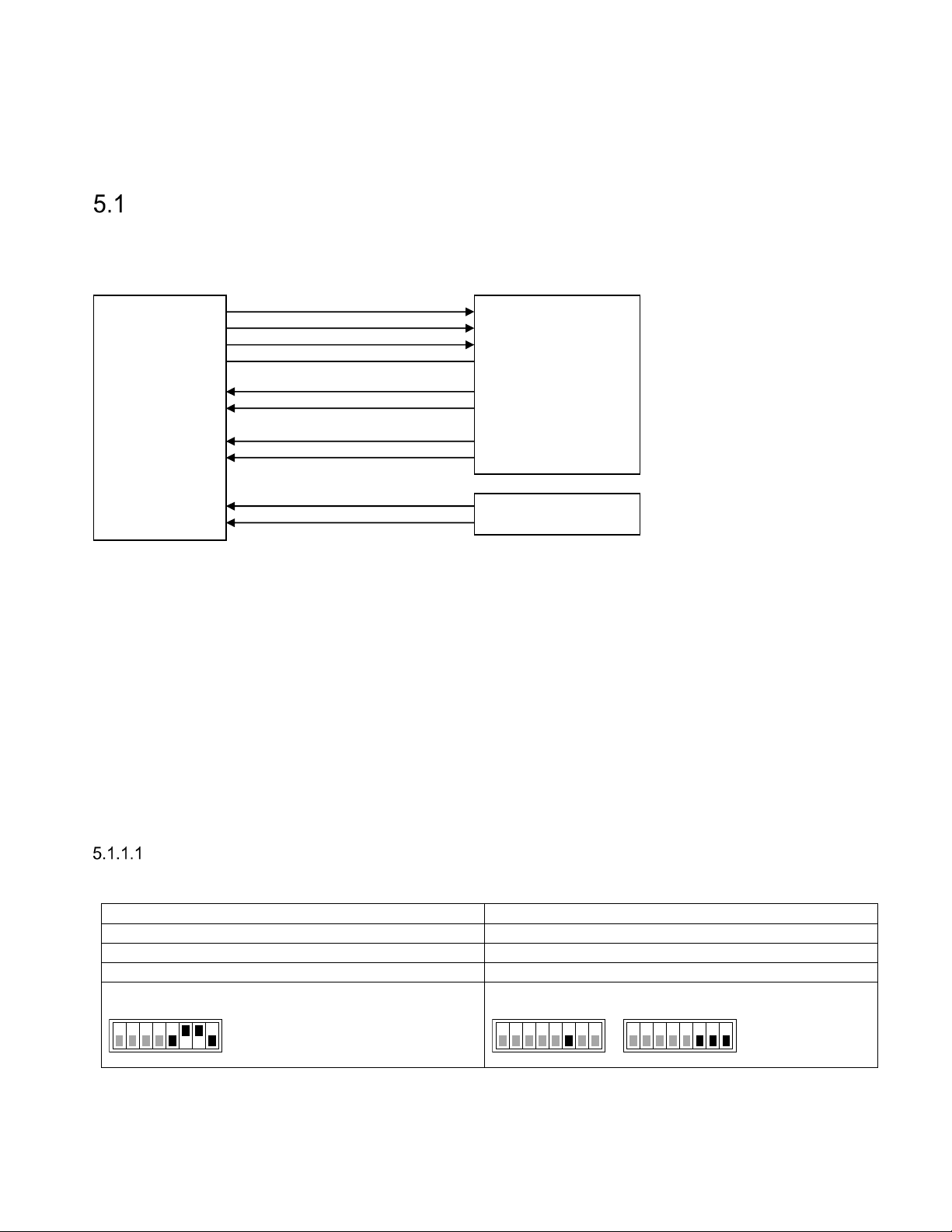
The reader can be connected to a typical access control system using Wiegand/Magstripe. The access
control system can control the reader's LED indicator using inputs IN1 and IN2. Input IN3 can be connected
to a presence detector such as an inductive loop. An overview is shown in Figure 22.
CL/LOAD
D0/CLK
D1/DATA
GND
IN1+
IN1-
Wiegand/Magstripe
Green LED
Access Control
System
IN2+
IN2-
Red LED
Vigilant Reader
IN3+
IN3-
Figure 22 Reader connected to access control system using Wiegand/Magstripe
For common access control systems, the reader can be configured using DIP switches as described in
section 5.1.1, "Easy Configuration", below. For other systems, all Wiegand/Magstripe settings are available
under Settings…/Interfaces…/Wieg/Mag in the web interface.
5.1.1 Easy Configuration
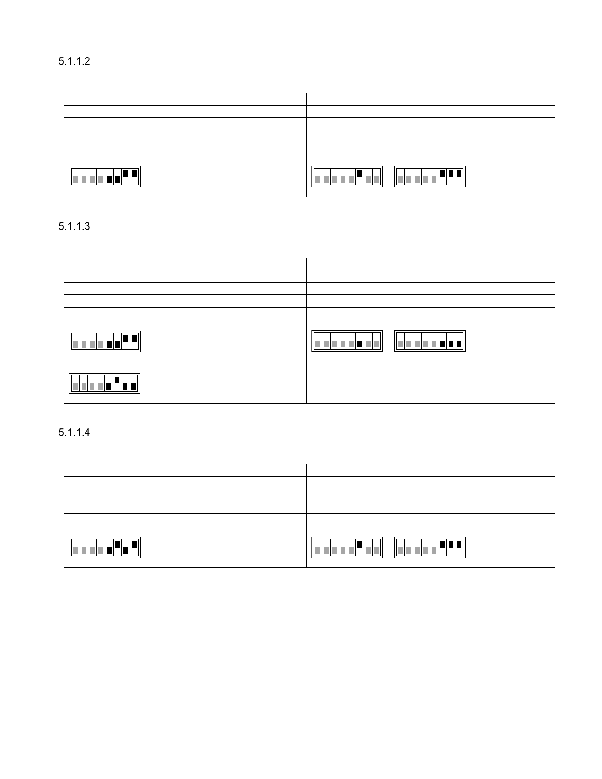
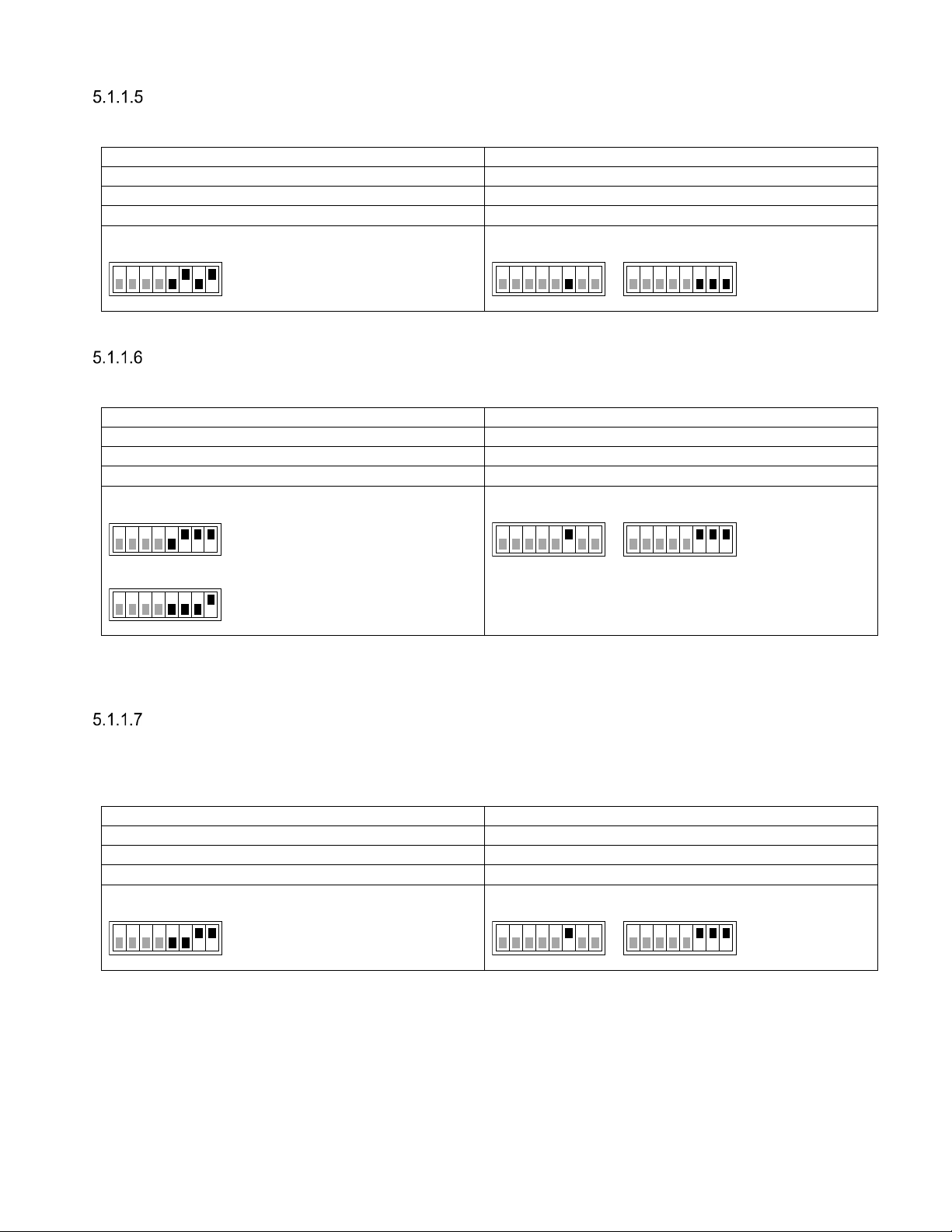
The reader can be configured to work with common access control systems using SW_DIP/S101:5-8.
When any of these switches are in the ON position, the reader is configured to report tags once, accept
SecureMarkID tags only, and use the specified Wiegand/Magstripe format.
The following sections describe how to connect the reader to different access control systems and how to
set the reader's DIP switches. The following format is used to describe cable connections:
[READER SIGNAL] [ACCESS CONTROL SYSTEM SIGNAL]
ASSA ARX/RX WEB (with 500RW22)
Configure the ARX/RX WEB system to use card type Wiegand.
Presence loop
Loop Controller
SW_DIP/S101 - Wiegand format: W34N
SW_DIP/S101
ON
1 8
IF_DIP/S301 - Vigilant pull-ups disabled
IF_DIP
1 8
Tested version: RX WEB PR300233 build-8418 version-17.2.0.5
ON
1 8
S301
ON
Page 27 of 36
Page 28
XT Series Reader Manual 13-111 P11D, 2017-10-03
GND
[READER
I/O]
-
IN1+
[READER I/O] 12V
CL/LOAD
N/C IN1-
[READER I/O] IO5
D0/CLK
[READER
DATA]
D0
IN2+
[READER I/O] 12V
D1/DATA
[READER
DATA]
D1
IN2-
[READER I/O] IO4
GND
0V
IN1+
N/C
CL/LOAD
N/C IN1-
N/C
D0/CLK
D0/CLK
IN2+
N/C
D1/DATA
D1/DATA
IN2-
N/C
SW_DIP/
S101
GND
[Conn. G]
-
IN1+
[Conn. G] +12V
CL/LOAD
[Conn. E] A
IN1-
[Conn. G] G
D0/CLK
[Conn. E] B
IN2+
[Conn. G]
+12V
D1/DATA
[Conn. E] C
IN2-
[Conn. E] R
AXIS A1001
Configure A1001 to use reader protocol Wiegand with "Dual LED" and set the card format to H10302.
SW_DIP/S101 - Wiegand format: W37N/H10302
SW_DIP/S101
ON
1 8
IF_DIP/S301 - Vigilant pull-ups enabled
1 8
Tested version: Firmware version 1.30.0
Bewator Entro
Configure the Bewator Entro system to use H10302 format.
IF_DIP/S301 - Vigilant pull-ups disabled
SW_DIP/S101
1 8
SW_DIP/S101
1 8
Bewator Entro ≥ 6.5:
ON
Wiegand format:
W37N/H10302
Older versions:
ON
Wiegand format:
W37R/H10302
1 8
Tested version: Bewator Entro 6.55.011
IF_DIP
IF_DIP
ON
1 8
ON
1 8
S301
ON
S301
ON
Bewator Omnis (with E2V)
The Vigilant reader behaves as a RB500 reader in Clock&Data mode.
SW_DIP/S101 - Magstripe format: M8N/H10320
SW_DIP/S101
ON
1 8
IF_DIP/S301 - Vigilant pull-ups enabled
1 8
IF_DIP
Tested version: Bewator Omnis 6.0.107
ON
1 8
S301
ON
Page 28 of 36
Page 29
13-111 P11D, 2017-10-03 XT Series Reader Manual
GND
0V
IN1+
12V
CL/LOAD
N/C IN1-
Green LED
D0/CLK
Clock/D1
IN2+
12V
D1/DATA
Data/D0
IN2-
Red LED
GND
DC- IN1+
N/C
CL/LOAD
N/C IN1-
N/C
D0/CLK
DATA0
IN2+
N/C
D1/DATA
DATA1
IN2-
N/C
SW_DIP/
S101
GND
[READER n]
- IN1+
[READER n] +
CL/LOAD
N/C IN1-
[OUT 1/2 ] 1
D0/CLK
[READER n]
A IN2+
[READER n] +
D1/DATA
[READER n] B
IN2-
[OUT 1/2 ] 2
Paxton Net2 Plus
Configure the Paxton system to use reader type "Clock & Data".
SW_DIP/S101 - Magstripe format: M8N/H10320
SW_DIP/S101
ON
1 8
IF_DIP/S301 - Vigilant pull-ups disabled
1 8
IF_DIP
ON
1 8
S301
ON
Tested version: Net2 Lite version 4.28.8417
RCO R-CARD M5 (with DB-50W)
The RCO system automatically detects the Wiegand format.
IF_DIP/S301 - Vigilant pull-ups enabled
SW_DIP/S101
1 8
SW_DIP/S101
1 8
Strap at P14*:
ON
Wiegand format:
W34N
No strap at P14:
ON
Wiegand format:
W26S/H10302
IF_DIP
ON
1 8
S301
1 8
ON
* To get all digits from the SecureMarkID tag, it is necessary to solder a strap at P14 on the RCO DB-50W
board. Without this strap it is only possible to get the last four digits from the tag.
Vanderbilt Aliro
On the circuit board in the access point, set the EOL jumper for the reader to OFF.
In the Aliro software, set reader type to "Wiegand" and card format to "H10302_37".
Configure Output_1 to "C&D/Wiegand green" and Output_2 to "C&D/Wiegand red".
SW_DIP/S101 - Wiegand format: W37N/H10302
SW_DIP/S101
ON
1 8
IF_DIP/S301 - Vigilant pull-ups enabled
IF_DIP
ON
1 8
S301
1 8
Tested version: Software version 1.0.0.5371, Access point firmware version 1.0.0.2022
ON
Page 29 of 36
Page 30
XT Series Reader Manual 13-111 P11D, 2017-10-03
RS485:TX+
[READER DATA n] B+
RS485:GND
[READER I/O n]
-
RS485:TX
-
[READER DATA n] A
-
RS485:TX+
PL400
-
3 + RS485:GND
-
RS485:TX
-
PL400
-4 -
RS485:TX+
[READER n] A
RS485:GND
[READER n]
-
RS485:TX
-
[READER n] B
OSDP (RS485)
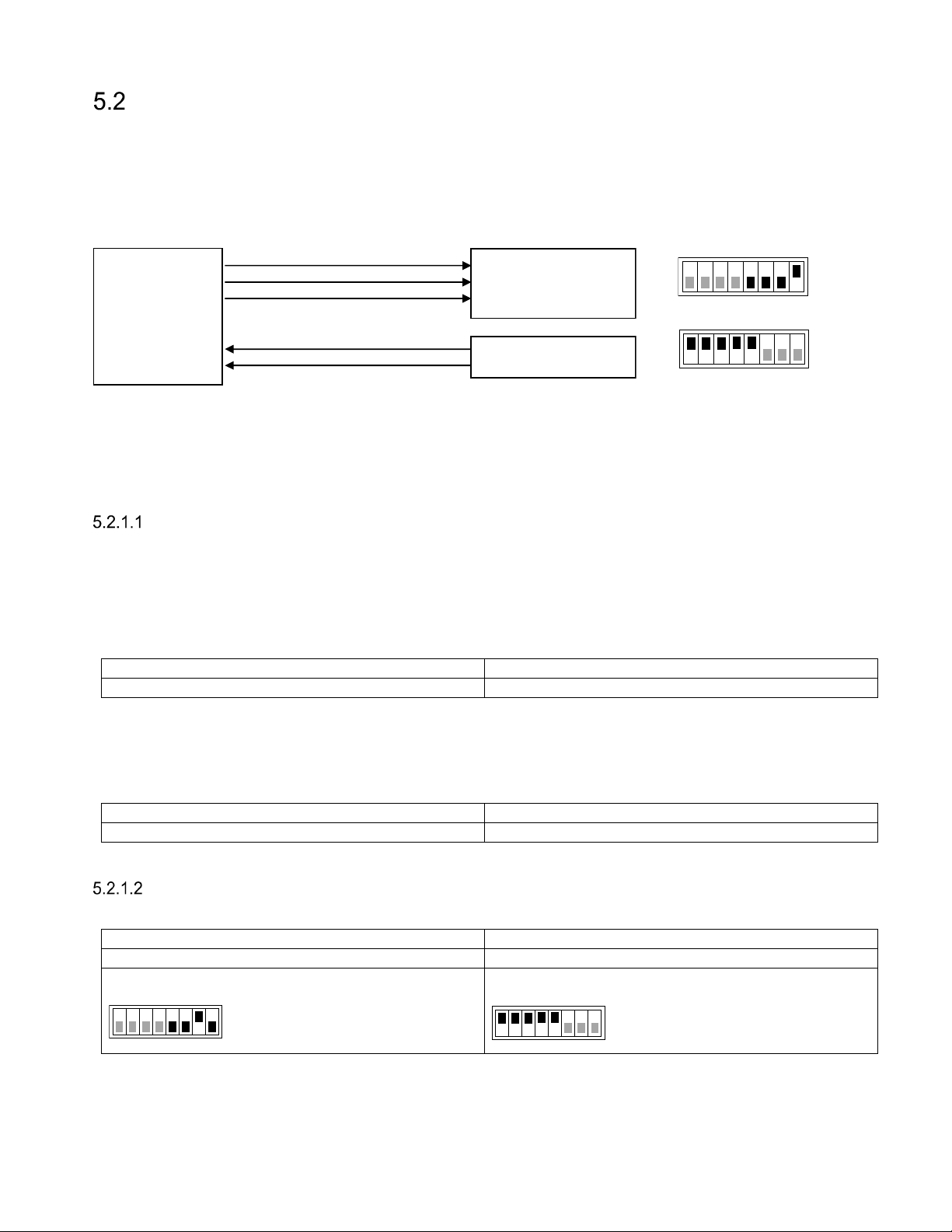
The reader supports the Open Supervised Device Protocol (OSDP) [5] for connection to access control
systems. OSDP communicates over 2-wire RS485 and can therefore be used with long cables and does
not require extra cables for LED and buzzer control. IF_DIP/S301:1-2 must be set to ON to enable 2-wire
mode on the reader. In most cases IF_DIP/S301:3-5 should also be set to ON to enable biasing and
termination. Input IN3 can be connected to a presence detector such as an inductive loop. Figure 23 shows
a typical connection diagram and the most common settings for SW_DIP/S101 and IF_DIP/S301.
TX+
TX-
GND
Reader
IN3+
IN3-
RS485
Presence loop
Access Control
System
Loop Controller
Figure 23 Reader connected to access control system using OSDP
All OSDP settings are available under Settings…/Protocol Settings…/OSDP. For common access control
systems, OSDP can also be enabled using SW_DIP/S101 as described below.
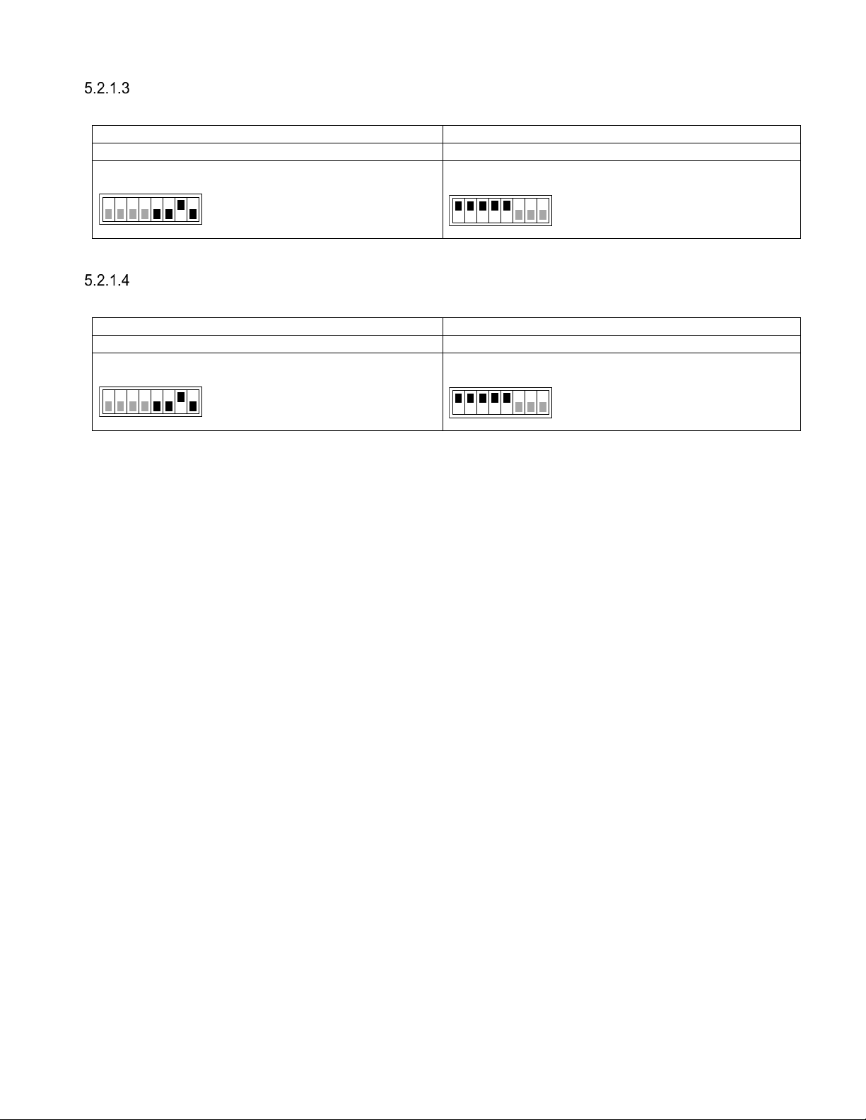
5.2.1 Easy Configuration
SW_DIP/S101
ON
1 8
IF_DIP/S301
ON
1 8
Default OSDP Mode
Set SW_DIP/S101 and IF_DIP/S301 as shown in Figure 23.
5.2.1.1.1 AXIS A1001
In the A1001 software, set the reader protocol to OSDP, RS485 half duplex. Define a new card format with
name SecureMarkID and bit length 32. Set the field map like this: Name: CardNr, Range: 1-32, Encoding:
BinLE2Int*.
Tested version: Firmware version 1.30.0
5.2.1.1.2 Bravida Integra
In the Bravida Integra Software: Set the communication protocol for card reader to OSDP. In card reader,
define proper card system. Set card data byte order to “MSB”. Set device bus address to 1.
Tested version: Integra SW version 7.0, C-NodeG2 FW version 21.70, S-NodeG2 FW version 20.20
Vanderbilt Aliro
In the Aliro software, set reader type to "extended OSDP".
SW_DIP/S101 - Vanderbilt AR40S-MF emulation
SW_DIP/S101
ON
IF_DIP/S301 - 2-wire RS485, bias and termination
IF_DIP/S301
ON
1 8
Tested version: Software version 1.0.0.5371, Access point firmware version 1.0.0.2022
Page 30 of 36
1 8
Page 31
13-111 P11D, 2017-10-03 XT Series Reader Manual
RS485:TX+
[Aux Serial] Tx +
RS485:GND
[Aux Serial
]
GND
RS485:TX
-
[Aux Serial] Rx
-
RS485:TX+
[SRB RS485] +
RS485:GND
[SRB PWR
] 0V
RS485:TX
-
[SRB RS485]
-
Vanderbilt SiPass integrated - DRI Door Module
Set card technology to Siemens OSDP in FLN configuration tool.
SW_DIP/S101 - Vanderbilt AR40S-MF emulation
SW_DIP/S101
ON
IF_DIP/S301 - 2-wire RS485, bias and termination
IF_DIP/S301
ON
1 8
1 8
Tested version: Software SiPass 2.65 SP4, Firmware ADD5100 (DRI) version 3.42; ACC FW 2.65.51
Vanderbilt SiPass integrated - ERI Door Module
Set card technology to Siemens OSDP in FLN configuration tool.
SW_DIP/S101 - Vanderbilt AR40S-MF emulation
SW_DIP/S101
ON
1 8
IF_DIP/S301 - 2-wire RS485, bias and termination
IF_DIP/S301
ON
1 8
Tested version: Software SiPass 2.65 SP4, Firmware ADE5300 (ERI) version 3.38; ACC FW 2.65.51
Page 31 of 36
Page 32

XT Series Reader Manual 13-111 P11D, 2017-10-03
Push (RS232, RS485, TCP/IP)
When a tag has been read, the reader can automatically push tag data to RS232, RS485 and a specified
TCP server. The Push protocol is enabled by default on RS232 and RS485. To push data to a TCP server
it is necessary to specify the IP address and TCP port of the server and enable the Push protocol under
Settings…/Interfaces…/Ethernet in the web interface.
The format of the pushed data can be configured under Settings…/Data Format. The default format is
decimal for SecureMarkID tags and hexadecimal for other tags.
TAGP (TCP/IP)
TagMaster Readers can be controlled and monitored using a protocol called TAGP. The TAGP protocol is
human readable and can be used over TCP/IP, RS232 and RS485. A terminal emulation program such as
PuTTY is all that is required to interact with TAGP.
The "TAGP Protocol Specification" [3] can be downloaded from www.tagmaster.com.
Use login name "partner" and password "245ghz".
PuTTY TagMaster Edition can be downloaded from ftp://partner:[email protected].
All TAGP messages start with a 4-character message identifier and ends with a new line character. To
initiate communication with the TAGP server in the reader, a client has to send a HELO message
specifying the required TAGP version. The TAGP server replies with a RPLY message:
HELOTAGP/2
RPLYHELO00
The client can then send commands to the reader. The most important commands are SET, SETS, GET,
and GETS. SET and GET sets and gets the current value of a variable. SETS and GETS sets and gets the
stored value of a variable. The stored value is used to initialize the variable at startup. The following
example shows how to set the LED to green:
SET LED=GREEN
RPLYSET 00
The reader sends events to the client when something happens. The following example shows a TAG
event that is sent when a tag has been read:
EVNTTAG 20140416151015810%00%07'%14l%00%00%00%00%00%00%00
Other Protocols
The reader supports a number of OEM protocols, including SKIDATA BLL4 and Kaba BPA/Bedanet. These
protocols are documented in separate protocol manuals that can be downloaded from www.tagmaster.com.
Page 32 of 36
Page 33
13-111 P11D, 2017-10-03 XT Series Reader Manual
6 Built-in Access Controller
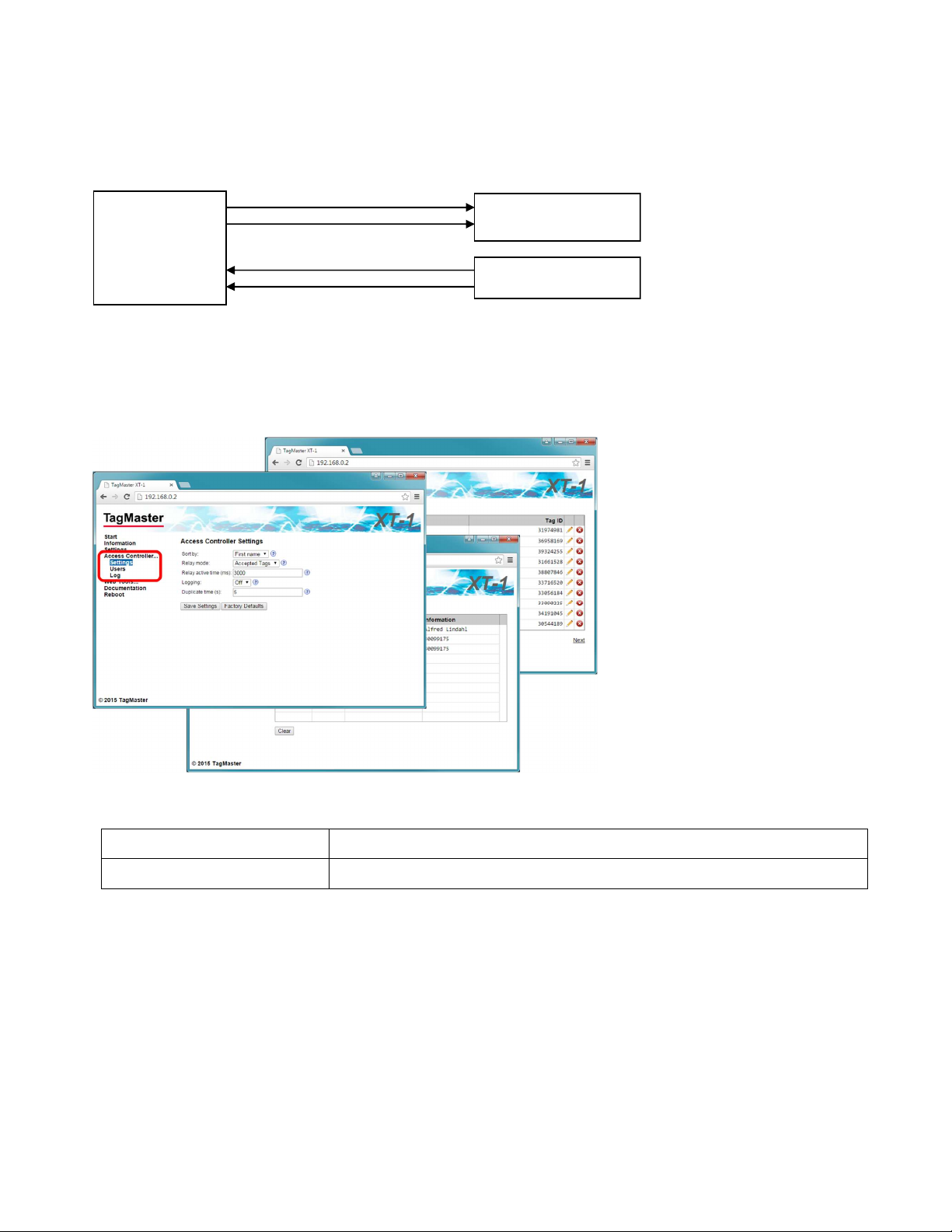
The reader has a built-in access controller that can control a barrier or gate using the reader's relay output.
All accesses can be logged. A presence indicator such as an inductive loop can be connected to input 3.
NO
Vigilant
Reader
Figure 24 Built-in access controller connection diagram
With XT Mini and XT-1 it is necessary to insert a microSD card into the microSD memory card slot to use
the access controller and/or log. Power off the reader before inserting or removing the microSD card!
The built-in access controller is configured using the web interface as shown in Figure 25.
COM
IN3+
IN3-
Relay output
Presence loop
Barrier/Gate
Loop Controller
Figure 25 Built-in access controller web interface (Settings, Users, Log)
Max number of users 1000
Max number of log entries 1000
Page 33 of 36
Page 34

XT Series Reader Manual 13-111 P11D, 2017-10-03
7 Troubleshooting
To facilitate troubleshooting, consider the following:
Make sure that the reader has correct supply voltage and sufficient current. Check the POWER
status indicator as described in section 3.5.
If using Ethernet communication, make sure that the network connection is ok. Check the ETH LINK
and SPEED status indicators as described in section 3.5.
If the IP address has been forgotten or firmware settings have been corrupted the reader can be
restored to factory default settings as described in section 4.5.
Make sure that working and correctly formatted EPC Gen 2 tags are being used.
8 Definitions and Abbreviations
AES Advanced encryption standard
ASCII American standard code for information interchange
AWG American wire gauge
CR Carriage return
DES Data encryption standard
DIP Dual in-line package
EPC Electronic product code
FCC Federal communications commission
LED Light emitting diode
LF Line feed
OEM Original equipment manufacturer
RFID Radio-frequency identification
PC Personal computer
SecureMarkID® A TagMaster implementation for improved Security using EPC tags
TAGP A TagMaster protocol for RFID reader communication
TCP/IP An Internet protocol suite
UMK Universal mounting kit
USB Universal serial bus
9 References
[1] 1117-129 XT-5 / XT-5 ETC D
[2] 06-147 UMK 193600 D
[3] 05-172 TAGP P
[4] EPC G
[5] SIA O
All documentation is available at ftp://partner:[email protected]/Documentation.
Page 34 of 36
EN 2 SPECIFICATION V
PEN SUPERVISED DEVICE PROTOCOL, HTTP
ROTOCOL SPECIFICATION
EVELOPER'S MANUAL
ATA SHEET
.2.0.1,
HTTP
://
WWW.GS1.ORG
://
WWW.SIAONLINE.ORG
Page 35
13-111 P11D, 2017-10-03 XT Series Reader Manual
Weight
0.8 kg (1.8 lbs)
2.3 kg (5.1 lbs)
XENOY™
UL94 certified XENOY
™ cover
FCC ID
M39XTMX
M39XTXX
M39XTMEX
Power consumption
4W (max 5W)
10W (max 12W)
8W (max 12W)
Operating frequencies
EU: 865.6
-
867.6 MHz, US: 902
-
928 MHz
Ingress protection
IP 66
EN 60068
-2-
1 Ad, EN 60068
-2-
2 Bd, EN 60068
-2-
14 Nb
Storage temperature
-40°C to +85
°
C (-40°F to +185°F)
Power supply
12-
24 VDC, IEEE 802.3at PoE+ (XT
-
5 and
XT-5 ETC
)
Inputs
3 (XT Mini and XT
-
1) or 4 (XT
-
5 and
XT-5 ETC
) isolated inputs
shared with Wiegand/Magstripe
Relay
1 relay output 60VDC, 2A
switches (XT Mini, XT
-
5, and
XT-5 ETC
)
Standards
EPC Gen 2, ISO 18000
-
63 (RAIN RFID)
Safety & health
EN 60950
-
1, EN 60950
-
22 & 1999/519/EC
HeadLight Tag: 227000
protocols
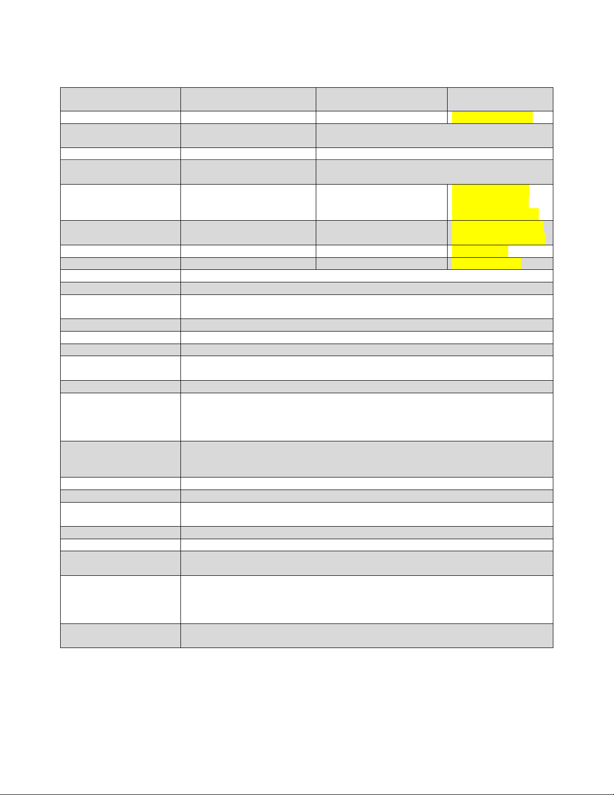
10 Technical Specification
Read range Up to 3 m (10 ft) Up to 8 m (26 ft) Up to 12 m (40 ft)
Dimensions 261x152x55 mm
(10.3x6.0x2.2 in)
Housing UL94 certified plastic
Part No. XT Mini eu: 152300
XT Mini us: 152400
Output power < 500 mW (e.r.p) XT-1 eu: 2W (e.r.p.)
Operating temperature -40°C to +60°C (-40°F to +140° F)
Outputs 3 (XT Mini and XT-1) or 4 (XT-5 and XT-5 ETC) isolated outputs
XT Mini XT-1 XT-5 / XT-5 ETC
300x300x60 mm (11.8x11.8x2.4 in)
Aluminium housing
XT-1 eu: 152500
XT-1 us: 152600
XT-1 us: 4W (e.i.r.p.)
XT-5 eu: 152800
XT-5 us: 152900
XT-5 ETC: 153800
XT-5 eu: 2W (e.r.p).
XT-5 us: 4W (e.i.r.p)
Interfaces RS232, RS485, Wiegand/Magstripe (2 interfaces on XT-5 and XT-5 ETC),
Ethernet (2-port switch on XT-1, XT-5, and XT-5 ETC, PoE+ on XT-5 and XT-5
ETC), microSD, USB device, USB host (XT-5 and XT-5 ETC), Tamper
Certificates CE Certificate according to R&TTE-directive 1999/5/EC and FCC
RoHS Directive 2002/95/EC and 2011/65/EU
WEEE 2002/96/EC
EMC EN 301489-1, EN 301489-3
Radio EN 302 208-1, EN 302 208-2
FCC: CFR 47, Part 15 subpart C
Mechanical EN 60068-2-27 Ea, EN 60068-2-64 Fh
Manuals and
documentation
Accessories Universal Mounting Kit: 193600
Communication
13-111 XT Reader Manual
05-172 TAGP Manual
ISO Card: 225000
WindShield Tag: 221000
TAGP, OSDP, and various OEM protocols
Page 35 of 36
Page 36

Technical Support
Phone: +46 8 632 19 50
E-mail: [email protected]
Office Address
TagMaster AB
Kronborgsgränd 11
164 46 KISTA
SWEDEN
Phone: +46 8 632 19 50
E-Mail: [email protected]
Web: www.tagmaster.com
13-111 P11D
 Loading...