

Page 1

TagMaster AB
TagMaster HW Installation Guide
Manual issue 03
TagMaster AB
Page 2

Disclaimer
The information in this document is subject to change without notice. While the
information contained herein is assumed to be accurate, TagMaster AB assumes no
responsibility for any errors or omissions.
Copyright
The copyright of this document is and will remain ours. No part of this document may be
reproduced or transmitted in any form or by means, electronic or mechanical, for any
purpose, without the express written permission of TagMaster AB.
FCC ID: M39S15XX
This device complies with part 15 of the FCC Rules.
Operation is subject to the following two conditions:
(1) This device may not cause harmful interference, and
(2) This device must accept any interference received,
including interference that may cause undesired
operation.
NOTE: This equipment has been tested and
found to comply with the limits for a Class
A digital device, pursuant to part 15 of the
FCC Rules. These limits are designed to provide
reasonable protection against harmful
interference when the equipment is operated
in a commercial environment. This equipment
generates, uses, and can radiate radio
frequency energy and, if not installed and
used in accordance with the instruction
manual, may cause harmful interference to
radio communications. Operation of this
equipment in a residential area is likely to
cause harmful interference in which case the
user will be required to correct the interference
at his own expense.
Caution
Information to user.
Changes or modifications not expressly
approved by the party responsible
for compliance could void the
user’s authority to operate the equipment.
Reg. No. 510278
TagMaster AB
Electrum 410
S-164 40 KISTA
Sweden
Tel: +46-8-632 19 50, Fax: +46-8-750 53 62
Email: [email protected], Web: http://www.tagmaster.com
2
Page 3

TagMaster AB
HW Installation Guide ABOUT THIS DOCUMENT Manual issue 03
TABLE OF CONTENTS
1 ABOUT THIS DOCUMENT...................................................................................... 5
1.1 Introduction ......................................................................................................... 5
1.2 Audience.............................................................................................................. 5
1.3 Definitions ........................................................................................................... 6
1.4 References ........................................................................................................... 6
1.5 Revisions ............................................................................................................. 6
2 SAFETY INSTRUCTIONS ........................................................................................ 7
2.1 General ................................................................................................................ 7
2.2 Installation ........................................................................................................... 8
3 SYSTEM COMPONENTS ......................................................................................... 9
3.1 Communicators.................................................................................................... 9
3.2 ID Tags ................................................................................................................ 9
4 ENVIRONMENTAL CONSIDERATIONS............................................................. 10
4.1 General .............................................................................................................. 10
4.2 Electromagnetic immunity ................................................................................ 10
4.3 Temperature....................................................................................................... 10
4.3.1 Communicators.......................................................................................... 10
4.3.2 Tags ........................................................................................................... 10
5 MECHANICAL INSTALLATION .......................................................................... 11
5.1 General .............................................................................................................. 11
5.2 Communicators.................................................................................................. 11
5.2.1 Mounting ................................................................................................... 11
5.2.2 Cables ........................................................................................................ 11
5.3 ID-Tags.............................................................................................................. 12
5.4 Accessories........................................................................................................ 12
5.5 Typical installations .......................................................................................... 13
5.5.1 Single lane identification........................................................................... 13
5.5.2 Multi lane identification ............................................................................ 13
5.5.3 How to handle and mount the tag.............................................................. 13
6 ELECTRICAL INSTALLATION............................................................................. 14
6.1 General .............................................................................................................. 14
6.2 Connection diagrams......................................................................................... 16
6.2.1 Single Communicator connection using port A for RS232C .................... 16
6.2.2 Single Communicator connection using port B for RS232C .................... 16
6.2.3 Direct Communicator multipoint connection using port B for 2-Wire
RS485 17
6.2.4 Digital I/O connections (example) ............................................................ 18
6.2.5 Power supply connection........................................................................... 19
6.3 Hardware adaptation.......................................................................................... 19
6.3.1 Jumper connections ................................................................................... 19
6.3.2 Adaptation of the S1500 or S1503 to 12 VDC power supply ................... 19
7 CABLES.................................................................................................................... 20
3
Page 4

TagMaster AB
HW Installation Guide ABOUT THIS DOCUMENT Manual issue 03
7.1 Power supply ..................................................................................................... 20
7.2 Digital I/O and DTMF....................................................................................... 20
7.3 RS232 ................................................................................................................ 20
7.4 RS485 ................................................................................................................ 20
7.4.1 2-Wires interface ....................................................................................... 20
7.4.2 4-Wires interface ....................................................................................... 20
8 START-UP ................................................................................................................ 21
8.1 General .............................................................................................................. 21
8.2 Inspection .......................................................................................................... 21
8.3 Verifying communication.................................................................................. 21
8.3.1 Serial host communication ........................................................................ 21
8.3.2 Communicator - Tag communication........................................................ 21
8.3.3 Digital I/O - communication with external devices .................................. 22
9 TROUBLE SHOOTING ........................................................................................... 23
9.1 An S1500/S1503 communicator seems not to read Tags.................................. 23
9.2 Unsuitable interface converters ......................................................................... 23
9.3 Interference........................................................................................................ 23
9.4 Using wrong address ......................................................................................... 23
9.5 Forgetting the free-wheel diode across inductive loads .................................... 23
9.6 Using different data speed in the Tag(s) and in the Communicator(s). ............24
9.7 Using an unsuitable power supply..................................................................... 24
4
Page 5
TagMaster AB
HW Installation Guide ABOUT THIS DOCUMENT Manual issue 03
1 ABOUT THIS DOCUMENT
1.1 Introduction
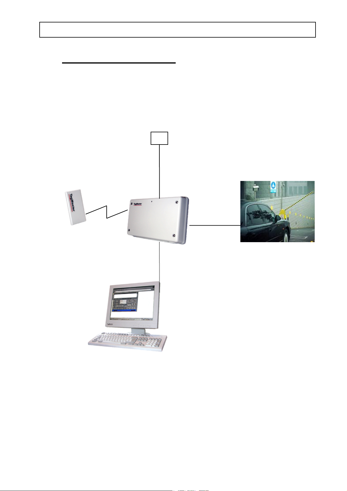
The basic elements of a TagMaster identification system are the electronic ID Tags (e.g.
S1251), the Communicator (e.g. S1500), and possibly a host computer.
ID-Tag
Communicator
This manual describes how to install TagMaster Communicators and Tags.
Power supply
Power supply cable
Digital I/O cable
Data cable
RS232 or RS485
Host computer
External device
(Traffic-light, Barrier etc)
1.2 Audience
The intended audience for this document is system integrators, installation engineers,
contractors or the like who have the task to install and commission TagMaster
identification systems. The audience is expected to have adequate experience and
education in the field of installation and commissioning of control and identification
systems and to be qualified for electrical installations.
5
Page 6

TagMaster AB
HW Installation Guide ABOUT THIS DOCUMENT Manual issue 03
1.3 Definitions
Communicator Device (e.g. S1500) used to read and write Tags in the
TAGMASTER system.
ConfiLib The TAGMASTER Library Software (ConfiLib) is the uniting
name of the device drivers that are included in all
S1500/S1501/host C-language software modules.
ConfiTalk Standard communication protocol. Used by Pyramid and Solid.
Included in ConfiLib.
Host IBM PC or compatible used as master computer in a
TAGMASTER system.
Pyramid Pyramid is the S1500 standard software delivered from factory.
S1500 with Pyramid is capable of taking decisions on its own when
a Tag has been read or when a movement has been detected. Refer
to the S1500 datasheet for further details.
Solid Solid is the S1501 and S1566 standard software delivered from
factory. This software receives ConfiTalk commands on the serial
port and executes them. This is the same as the ConfiTalk only
mode of the S1500.
Tag ID-carrier (e.g. ScriptTag S1251) in the TAGMASTER system
which is read/writable via microwaves, using a Communicator.
1.4 References
Communicator S1500&S1501 data sheet DS1500
Communicator S1503 data sheet DS1503
ScriptTag S1251 data sheet DS1251
ScriptTag HD S1450 data sheet DS1450
ScriptTag HT S1350 data sheet DS1350
MarkTag S1255 data sheet DS1255
MarkTag HD S1455 data sheet DS1455
Card holder WinFix S1951 data sheet DS1951
Card holder Cardkeep S1953 data sheet DS1953
Mounting bracket S1952 data sheet DS1952
RS232/RS485 converter S1942 DS1942
TagMaster Programmer’s Guide 510211
1.5 Revisions
Issue Date Description
01 971211 First issue
02 980623 Second issue
03 030506 Third issue
6
Page 7

TagMaster AB
HW Installation Guide SAFETY INSTRUCTIONS Manual issue 03
2 SAFETY INSTRUCTIONS
This chapter gives an overview of necessary safety precautions for the TAGMASTER
system.
2.1 General
This Installation Manual shall be carefully read before any installation works is
performed. Special attention shall be paid to this page and the statements in boxes
throughout the manual.
The contents of this document are not binding. If any significant difference is found
between the product and this document, please contact TagMaster AB for further
information
We reserve the right to modify products without amending this document or advising the
user.
We recommend using personnel authorised by TagMaster for all installation, service and
repair and the use of TagMaster genuine spare parts. TagMaster AB will not otherwise
assume responsibility for the materials used, the work performed or any consequences of
the same.
Check the contents of the shipment for completeness and possible damage. If the
contents are incomplete or damaged, a claim should be filed with the carrier immediately
and the TagMaster Sales or Service organisation or the TagMaster representative should
be notified in order to facilitate repair or replacement of the equipment.
The equipment described in this manual is designed to be used by properly trained
personnel only. Installation, adjustments and maintenance of the exposed equipment shall
be carried out by qualified personnel who are aware of the hazards involved and who are
qualified for electrical installations.
For correct and safe use of this equipment, it is essential that both operating and service
personnel follow generally accepted safety procedures in addition to the safety
precautions specified in this manual.
Specific warning and caution statements are used throughout this manual.
CAUTION is used to indicate correct operation or maintenance procedures in order
to prevent damage to, or destruction of the equipment or other property.
WARNING indicates a potential danger that requires correct procedures or
practices in order to prevent injury to personnel.
Whenever it is likely that safe operation is impaired, the equipment must be made
inoperative and secure against unintended operation. The appropriate servicing authority
must then be informed.
7
Page 8

TagMaster AB
HW Installation Guide SAFETY INSTRUCTIONS Manual issue 03
2.2 Installation
• Before any other connection is made, the equipment shall be mounted so that the
metallic chassis is connected to protective ground.
WARNING Interruption of the chassis connection with protective ground can
make the equipment dangerous if it is connected to a defective power supply.
• The power supply used to provide the equipment with 24 or 12 VDC must comply
with all relevant safety regulations. It must also be made for connection to the local
mains voltage and be able to provide the necessary power without producing excessive
heat.
• Fuses shall only be renewed by a qualified person who is aware of the risks involved.
The use of repaired fuses is prohibited.
• Capacitors inside the equipment can hold their charge even if the equipment has been
disconnected from all voltage sources.
• All PCB’s removed from the equipment must be adequately protected against damage
and all normal precautions regarding the use of tools must be observed.
• The equipment must be disconnected from all voltage sources before any installation
or service work is made.
CAUTION Damage may be the result if;
- The equipment is switched on when parts are removed from the PC board.
- A PCB is removed within one minute after switching off the equipment.
8
Page 9

TagMaster AB
HW Installation Guide SYSTEM COMPONENTS Manual issue 03
3 SYSTEM COMPONENTS
The hardware of a TAGMASTER system is described briefly below.
3.1 Communicators
The S1500/S1503 Communicator is a device for reading and writing ID Tags using 2.45
GHz microwaves. It is powered with 24 VDC but can be adopted for 12 VDC. The S1500
has built-in antennas for communication with the Tags and various serial interfaces for
communication with a host computer. The Communicator also provides a movement
detection function which can detect moving objects in the reading zone (also non-Tagged
objects). One hundred frequency channels are available. The microprocessor is a 16-bit
Hitachi H8/534. The S1500 is equipped with Flash EEPROM for program code and
database. Designed for different installations, the S1500/S1503 comprises a wide range
of I/O devices, including relays, optocouplers, DTMF receiver, LED, buzzer and a
control panel. It also has a real-time-clock, 2/4Wire RS485 interface and a connector for
an optional board.
The S1501/S1504/S1566 is a less advanced Communicator and is powered by 12 VDC
only. It has no database memory, no real-time-clock, no optional card connector and the
second serial interface is only 2Wire RS485. Refer to the datasheets for details.
3.2 ID Tags
An ID Tag is a device carrying ID information that can be read at a long distance using
microwaves. Versions that can be read at a distance of up to 6 meters with the
Communicator S1503/S1504 are available. The actual reading range depends on the
Communicator type. Also different shaped versions of the tags are available. Some have
the shape of a credit card but is slightly thicker. Each Tag has its own unique 8-digit
mark. It is possible to read many Tags concurrently. To maintain the information, to get
the long reading range and the high communication speed, a lithium battery cell is used.
The life of the cell is depends of the Tag type but is typically 5 - 10 years and
independent of how often the Tag is used. Certain types of Tags (e.g. ScriptTag S1251)
can also be written by the user. The Tags then have a static RAM memory array that can
be configured for different memory sizes; 14, 154 or 574 bits (32 bit checksum not
included in these figures). Refer to the Tag (e.g. S1251 or S1450) data sheet for details.
9
Page 10

TagMaster AB
HW Installation Guide ENVIRONMENTAL CONSIDERATIONS Manual issue 03
4 ENVIRONMENTAL CONSIDERATIONS
4.1 General
Microwaves have, during more than a decade, proven to be the most reliable technology
for identification systems. In particular, microwaves are unaffected by the normal
electromagnetic background noise found in industries and elsewhere. They also form a
base for products that have to withstand other rough environmental conditions as high
temperatures, chemicals, shock and vibrations
4.2 Electromagnetic immunity
The TagMaster system has been tested and approved, in operation, according to the IEC
standards. This guarantees trouble-free operation in demanding electromagnetic
environments.
Electromagnetic interference on the microwave link
Industrial noise is typically present in the KHz and low MHz frequency band. The
TagMaster system is only receptive for frequencies closed to 2.45 GHz so typical
industrial noise will not affect the microwave communication. Transients from spotwelding equipment or from switching on other welding equipment, soldering machines
and fluorescent lamps may produce short pulses around 2.45 GHz. However, since the
TagMaster system, if interfered, will retransmit the entire message very fast there is in
most cases ample time for a re-transmission. If strong microwave fields, from for instance
microwave dryers, can be suspected, TagMaster AB should be consulted.
Electromagnetic interference in cables
By selecting a suitable communications interface, using specified cables and proper
shielding and grounding, optimum communication reliability is ensured.
4.3 Temperature
4.3.1 Communicators
In most applications, normal convection cooling is enough. In applications where heat is
generated close to the Communicator, forced cooling or heat shields may be necessary.
4.3.2 Tags
TagMaster Tags are available for operation in various ambient temperatures ranging from
-40°C up to 85°C, refer to the data sheets. The specified reading range is valid for
normal ambient temperature conditions. If reading range is critical and the intended
operating temperature deviates from normal ambient temperature TagMaster AB should
be consulted.
10
Page 11

TagMaster AB
HW Installation Guide MECHANICAL INSTALLATION Manual issue 03
5 MECHANICAL INSTALLATION
This chapter describes the procedure of installing the TagMaster units mechanically.
It is assumed that the location of Communicators and Tags are specified, and the
communication distances and movement speeds are considered during the project
planning phase. Likewise it is assumed that the project planning is well documented.
5.1 General
Microwaves penetrate wood, dirt, paint, plastic, and most other non metallic materials.
The TagMaster system employs circular polarisation and can therefore also often be used
when metal surfaces are in the vicinity of the antenna and Tag, especially if the Tag is
moving. In such cases however, adjustment of the Tag/Communicator position and
distance may be necessary to find the best position. Always combine this with tests to
verify that the installation will work.
5.2 Communicators
5.2.1 Mounting
• Position the Communicator with the cable entries pointing downwards and so that the
device is easily accessible for service.
• Mount the Communicator in an adjustable holder. (ComFix S1952 or PoleFix S1956 is
recommended) and direct it so that it’s lobe beam covers the position of the Tag(s).
• If Tags are to be mounted in car wind screens it is recommended to mount the
Communicator approximately 2 meters up and tilted down for best performance. Refer
to the typical installation illustrations in section 5.5.
5.2.2 Cables
To keep the sealing on a high level the Communicator should be mounted against a flat
surface like for instance a mounting plate. It should be fastened on the mounting plate
using the mounting holes located in the corners of the Communicator back panel. If the
sealing level of IP 54 must be kept, then the cables must enter the Communicator using
standard electrical feed through bushings.
11
Page 12

TagMaster AB
HW Installation Guide MECHANICAL INSTALLATION Manual issue 03
5.3 ID-Tags
The front side of the ID-Tags must be oriented towards the front side of the
Communicator. The backside of the tag has a type label on it. To get the maximum
communication range the front surface of the Tag should be in parallel with the front side
of the Communicator. If the Tag is miss-aligned relative to the front side of the
Communicator, the communication range is reduced. Refer to the actual product
datasheets for details.
Due to TagMaster’s circular polarisation the rotational orientation of the Tag relative the
Communicator is uncritical. The Tags can be mounted on any flat surface. If it is to be
expected that the mounting surface material, when warmed up, can expand in a different
way than the Tag, the Tag must be mounted in such a way that the material expansion
does not damage the Tag.
When screwing the Tags directly on to a surface, the screw must not be secured by
pulling it until it does not move anymore. Instead a threaded hole should be used and the
screw should be pulled until the Tag is just fixed. Then the screw should be secured
using a washer and nut from behind.
For the credit card shaped Tags S1251 and S1255, TagMaster AB offers holders for use
in vehicle windows or for personal carrying. (WinFix S1951 and Cardkeep S1953). For
permanent mounting of the Tag in a vehicle window the CardTape S1954 is
recommended.
5.4 Accessories
The following TAGMASTER accessories are available:
Product Art.No Description
RS485 Converter S1942 Interface converter for RS232C - RS485 2Wires
WinFix S1951 Tag holders for vehicle window mounting
CardTape S1954 Tag tape for fixed mounting on wehicle window.
CardKeep S1953 Tag holders for personal carrying
ComFix S1952 Adjustable Communicator holder
PoleFix S1956 Pole fastening bracket
12
Page 13
TagMaster AB
HW Installation Guide MECHANICAL INSTALLATION Manual issue 03
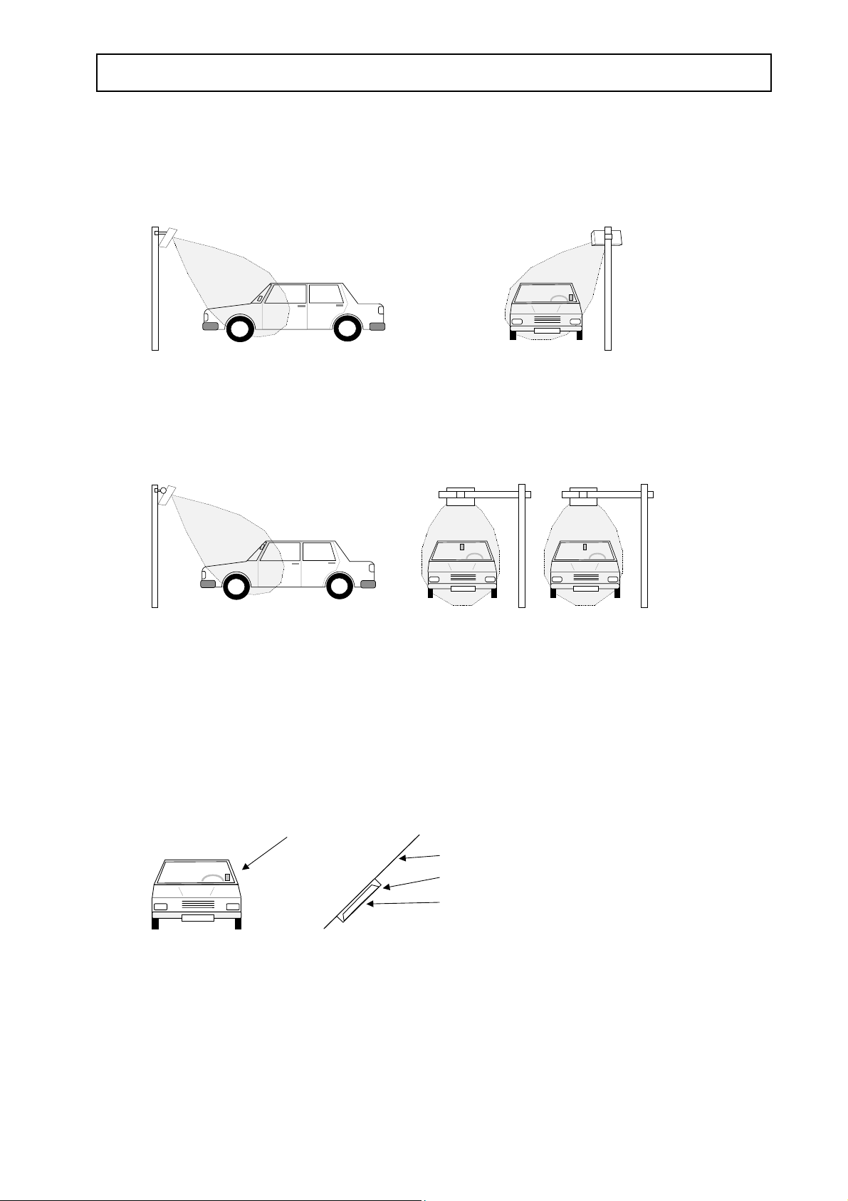
5.5 Typical installations
5.5.1 Single lane identification
5.5.2 Multi lane identification
For optimum performance:
• Keep Tag and Communicator surfaces as parallel as possible
• Distance Tag - Communicator < 70% or less of maximum reading range, refer to the
actual data sheet
• The windscreen might reduce maximum reading range with up to 0.5 meter
5.5.3 How to handle and mount the tag
Tag in windscreen
The tag should be mounted on the inside of the windscreen in a tag holder (WinFix).
Note that the front side of the tag inside the holder should face the reader.
Windscreen
Tag holder
Tag
13
Page 14
TagMaster AB
HW Installation Guide ELECTRICAL INSTALLATION Manual issue 03
6 ELECTRICAL INSTALLATION
This chapter describes the procedure of electrically installing TagMaster Communicators.
Three basic connection-types are described:
• Host connection
• Digital I/O connection
• Power supply connection
It is assumed that the location of Communicators and Tags are specified, and that cable
paths and cable types are considered during the project planning phase. Likewise it is
assumed that the project planning is well documented.
6.1 General
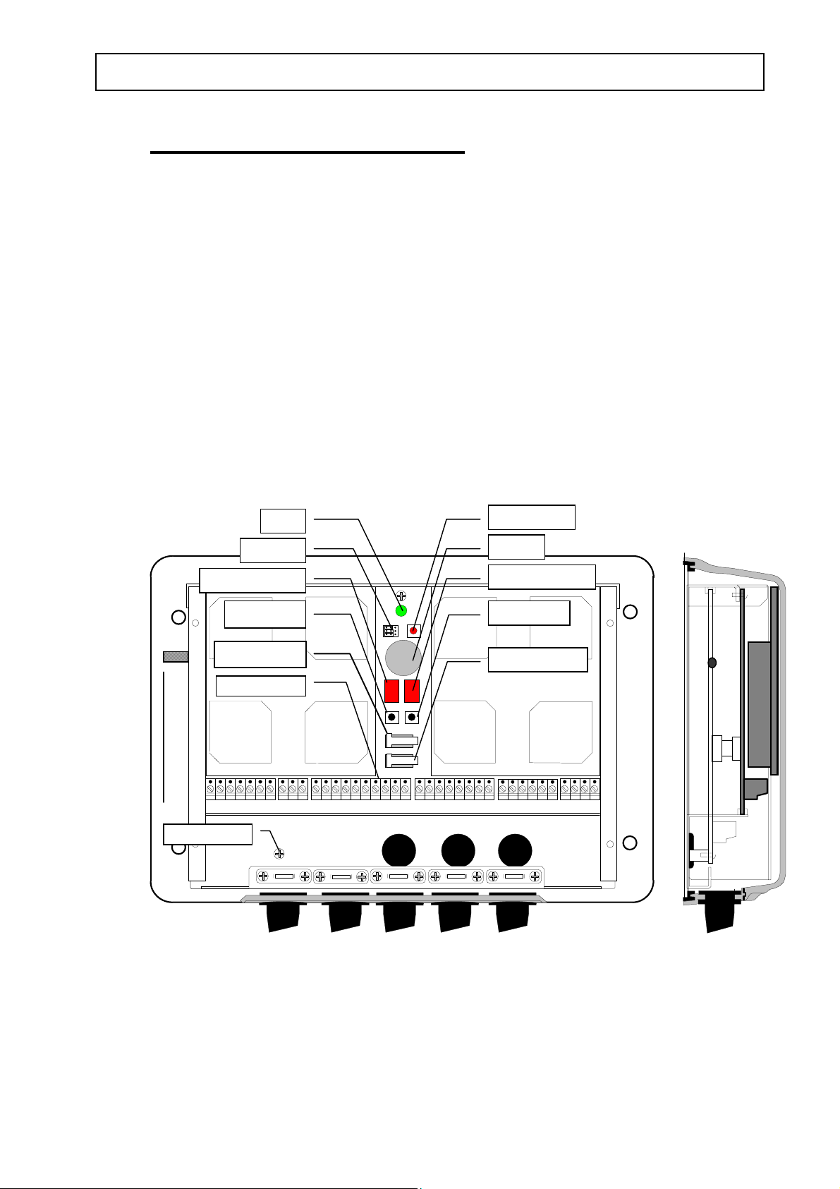
To make connections to the Communicator the cover must be removed. Terminal blocks
for connection of the external cables and jumpers for hardware adaptation are located
under the cover according to following illustration of an S1500 communicator:
LED
Reset button
Jumpers
7-segm. display
Push button
Tamper switch
Terminal
J1 J2 J3 J4 J5 J6
Ground screw
Buzzer
7-segm. display
Push button
Tamper switch
Connections to the Communicator are made using the terminal blocks J1 - J6.
Please note that the 7-segm. display, the buzzer and the upper tamper switch are
components not present in the S1501. The use of these, as well as the use of the push
buttons, is communicator software dependent and therefore described in the
communicator software documentation.
Screened cables shall be used with screens clamped according to the figure below.
14
Page 15
TagMaster AB
HW Installation Guide ELECTRICAL INSTALLATION Manual issue 03
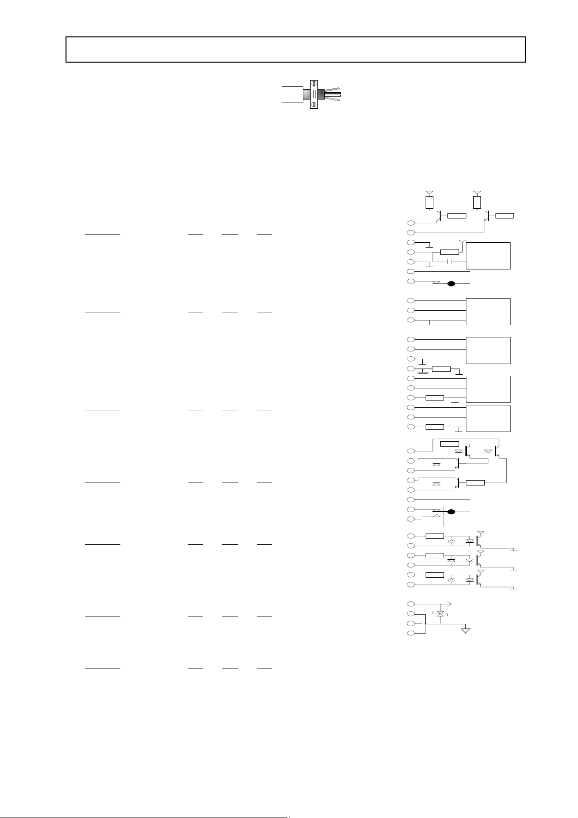
The electrical data and the connection diagram are shown below
Notes: The S1500/S1503 supports 24VDC power supply and can be adopted for 12VDC.
DTMF (Terminal block J1)
2-wire interface to receive a dual tone signal and to power a
DTMF device.
Parameter
Line volt. @ 10 mA 4.1 4.5 V
Tone level -26 0 dBm
RS 232 - host and terminal (Terminal block J2)
Default: 9600 bps, 8 bits, no parity, 1 stop bit, ConfiTalk
address 1
Parameter
Baud rate 1.2 19.2 kbits/s
Data bits 7 8 bits
Stop bits 1 2 bits
Parity no - odd - even
RS 485 - host (Terminal block J3)
Full (4 wire) or half duplex (2 wire). Default: 9600 bps, 8 bits,
no parity, 1 stop bit, ConfiTalk address 1
Parameter
Baud rate 1.2 38.4 kbits/s
Data bits 7 8 bits
Stop bits 1 2 bits
Parity no - odd - even
Open collector outputs (Terminal block J4)
Parameter
Allowed volTage 1 30 V
Sink current Out 1 0 500 mA
Sink current Out 2 0 100 mA
Relay (Terminal block J4)
Parameter
Switch current 2 A
Switch volTage DC 220 V
Switch volTage AC 125 V
Switch power 50 W
Optocoupler inputs (Terminal block J5)
Parameter
High volTage 2.4 30 V
Low volTage 0.0 0.2 V
Power (Terminal block J6)
Parameter
24VDC Supply volTage 20 28 V
12VDC Supply volTage 10 14 V
Consumption 24V 150 mA
Consumption12V 500 mA
The S1501 supports 12VDC power supply only.
The S1501 does not support RS485-4Wire interface
Min Max Unit
Min Max Unit
Min Max Unit
Min Max Unit
Min Max Unit
Min Max Unit
Min Max Unit
J1: 1
J2: 1
J3: 1
J5: 1
J6: 1
2
3
4
5
6
7
2
3
2
3
4
5
6
7
8
9
10
2
3
4
5
6
7
8
2
3
4
5
6
2
3
4
LED 1
LED 2
G ndLED
SDTMF
RtnDTMF
Tamp a
Tamp b
Tx232a
Rx232a
G nd 232a
Tx232b
Rx232b
G nd 232b
CGnd
T x-/R x-48 5
Tx+/Rx+485
G nd485t
Rx485-
Rx485+
G nd485r
Outspl1J4: 1
Out 1c
Out 1e
Out 2c
Out 2e
R1c
R1b
R1m
In 1 a
In 1 c
In 2 a
In 2 c
In 3 a
In 3 c
Spl 1
Rtnspl 1
Spl 2
Rtnspl 2
470 470
100
Cover on
Standard IC
Standard IC
100
100
100
2,2 k
2,2 k
2,2 k
Standard IC
Standard IC
DC/D C converter
or linear regulator
Power supply Gnd
DTMF
rec eiver
Tamper switch
15
Page 16
TagMaster AB
HW Installation Guide ELECTRICAL INSTALLATION Manual issue 03
6.2 Connection diagrams
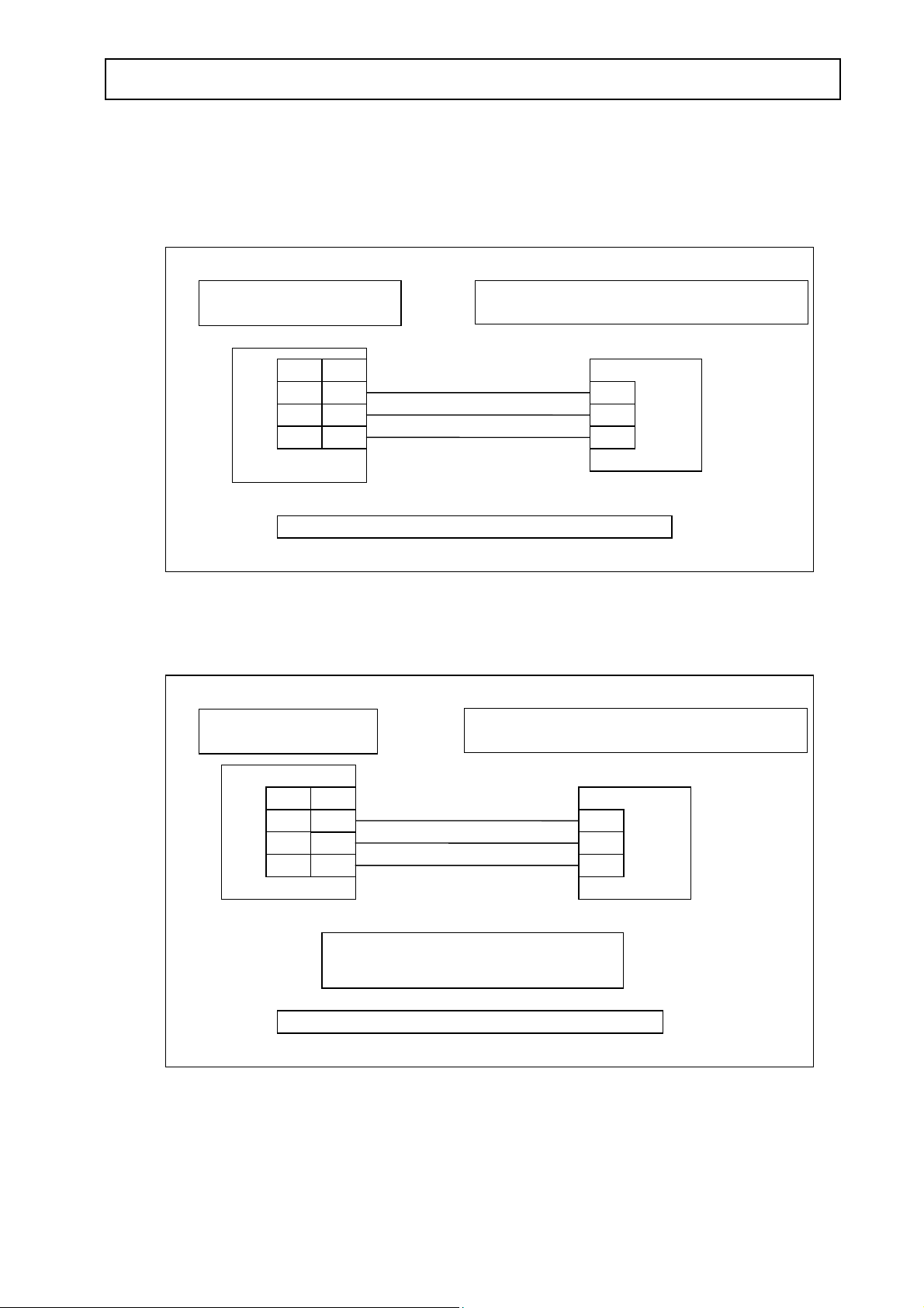
6.2.1 Single Communicator connection using port A for RS232C
Personal Computer
COM1
25 pin
RX 3
TX 2
Gnd 7
9 pin
RX 2
TX 3
Gnd 5
Note 1: Concerning cables, refer to paragraph 7
Communicator 1500/S1503/S1501/S1504
Port RS232a
1 TX
2 RX
3 Gnd
6.2.2 Single Communicator connection using port B for RS232C
Personal Computer
COM1
Communicator S1500/S1503/S1501/S1504
Port RS232b
J2
25 pin
RX 3
TX 2
Gnd 7
9 pin
RX 2
TX 3
Gnd 5
RS232/RS485 jumpers = RS232
Note 1: Concerning cables, refer to paragraph 7
1 TX
2 RX
3 Gnd
J3
16
Page 17
TagMaster AB
HW Installation Guide ELECTRICAL INSTALLATION Manual issue 03
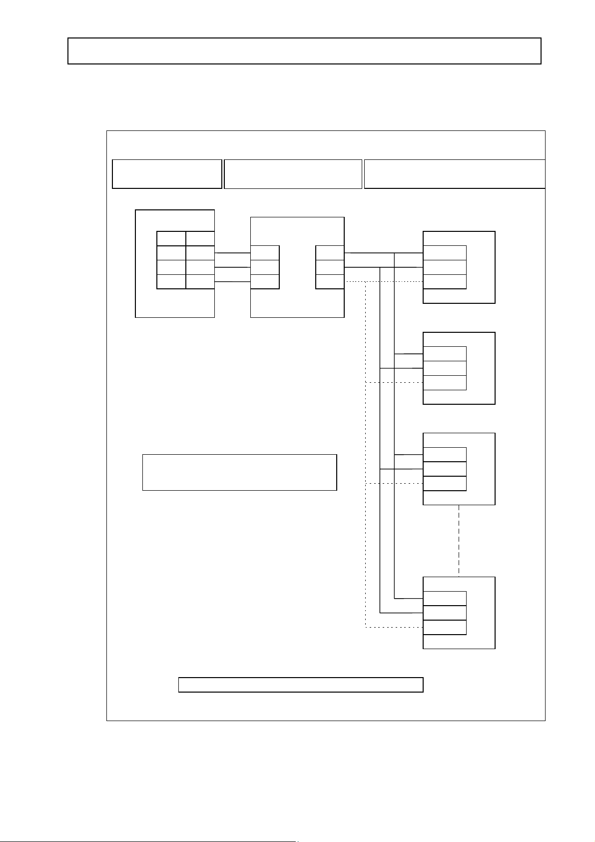
6.2.3 Direct Communicator multipoint connection using port B for 2-Wire RS485
Personal Computer
COM1
25 pin
RX 3
TX 2
Gnd 7
9 pin
RX 2
TX 3
Gnd 5
RS232/RS485 jumpers = RS485
RS485
Converter S1942/00
RS232/RS485 2-wires
2 TX
3 RX
5 Gnd
Data -
Data +
Gnd
Communicator S1500/S1503/S1501/S1504
Port RS485
5 RX/TX -
6 RX/TX +
7 Gnd
5 RX/TX -
6 RX/TX +
7 Gnd
5 RX/TX -
6 RX/TX +
7 Gnd
J3 1
J3
J3
2
3
Note 1: Concerning cables, refer to paragraph 7
17
5 RX/TX -
6 RX/TX +
7 Gnd
J3
n (max 32)
Page 18
TagMaster AB
HW Installation Guide ELECTRICAL INSTALLATION Manual issue 03
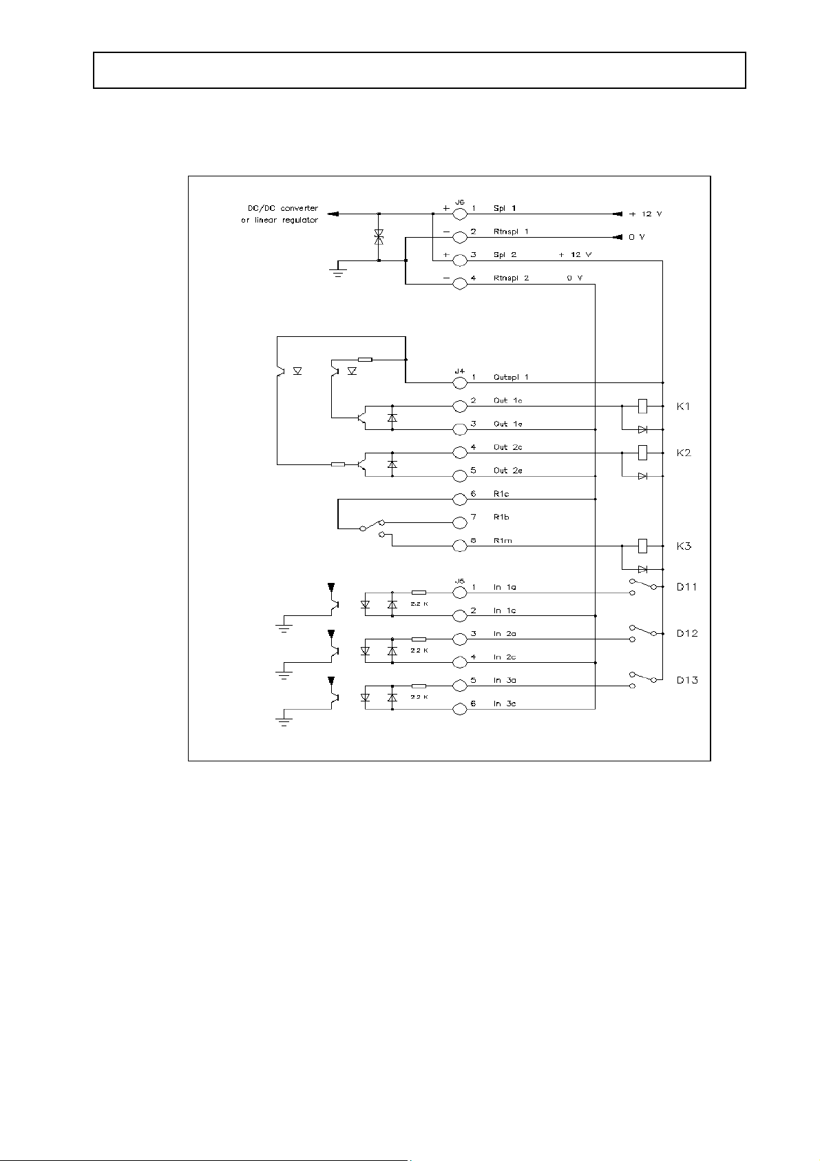
6.2.4 Digital I/O connections (example)
Optocoupler inputs: ON = from 2.4 to 30 VDC OFF = from 0.0 to 0.2 VDC
Optocoupler output 1: Voltage from 1 to 30 VDC Sink current from 0 to 500 mA
Optocoupler output 2: Voltage from 1 to 30 VDC Sink current from 0 to 100 mA
Relay output: Switch current: 2 A
Switch voltage: 220 VDC
Switch voltage: 125 VAC
Switch power: 50W
CAUTION
Omission of the protective free-wheel-diodes across K1, K2 and K3 may damage the
Communicator.
18
Page 19
TagMaster AB
)
)
)
)
HW Installation Guide ELECTRICAL INSTALLATION Manual issue 03
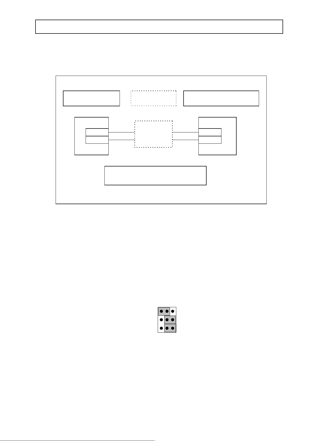
6.2.5 Power supply connection
Power Supply
24VDV
or 12VDC
+ 24 V DC
0 V DC 2 Rtnsp 1
S1500/S1503: 20-28V DC - Consumption = 150 mA
S1501/S1504: 10-14V DC - Consumption = 500 mA
6.3 Hardware adaptation
Power supply filter
to 6.3.3
Refer
Communicator
S1500/S1503/S1501/S1504
1 Spl 1
J6
This section describes how to set jumpers and how to adapt the S1500 or S1503 for
12VDC
6.3.1 Jumper connections
There are jumpers for selecting if port B should be configured as RS232 or RS485 and if
the RAM backup battery shall be connected. Se figure below.
Battery on Battery off
Host RS232 (Tx
Host RS232 (Rx
Host RS485 (Tx
Host RS485 (Rx
6.3.2 Adaptation of the S1500 or S1503 to 12 VDC power supply
CAUTION
This must be done by properly trained personnel only
Under the rightmost antenna, additional jumpers are available for setting the
Communicator for power from a 12 or 24 VDC power supply. Marking on the PC boards
indicate how to set these jumpers. The factory setting is 24VDC.
19
Page 20

TagMaster AB
HW Installation Guide CABLES Manual issue 03
7 CABLES
7.1 Power supply
Cable specification:
AWG 0.5 mm
Number of wires 2
VolTage rating 300 V
Temperature rating +80°C
Recommended external diameter > 5 mm
Maximum length 100 m
7.2 Digital I/O and DTMF
Cable specification:
AWG 0.5 mm
Number of wires Application dependent
VolTage rating 300 V
Temperature rating +80°C
Recommended external diameter > 5 mm
Maximum length 100 m
7.3 RS232
2
2
Cable specification according to EIA RS232C
Recommended type: Belden 9184 or Belden 9502
7.4 RS485
Cable specification according to EIA RS485
7.4.1 2-Wires interface
Recommended type: Belden 9841
7.4.2 4-Wires interface
Recommended supplier: Belden 9841
20
Page 21

TagMaster AB
HW Installation Guide START-UP Manual issue 03
8 START-UP
8.1 General
After having completed the physical installation as described in previous sections, a
systematic check of the installation and system performance should be carried out.
This work can be divided into two parts: inspection and performance verification.
When something does not work as expected the tips in paragraph TROUBLE
SHOOTING may be valuable.
8.2 Inspection
• Ensure that there are no metal objects between the Communicator and the Tag in the
position(s) where communication is to take place.
• Ensure that the Tags and Communicators are aligned according to the project
documentation. Maximum communication distances and communication paths are
achieved when Tag and Communicators are in parallel. Communication at maximum
specified distance and misalignment should be avoided.
• Ensure that the Communicators are not placed in positions, where they are exposed to
unnecessary heat or electromagnetism.
8.3 Verifying communication
8.3.1 Serial host communication
Connect a PC to the prepared host connection and verify that the PC can communicate
with the Communicator. If the actual Communicator is a standard S1500/S1503 equipped
with Pyramid software this can be made by using the TagMaster demo software Saccess
that runs under DOS, Windows 3.1, 95/98/ME and NT/2000/XP. An alternative to
Saccess is the TagMaster test software ConfiTalk Commander which can be used for any
Communicator where the resident software was developed using ConfiLib and where
ConfiTalk is enabled, for example the S1501with Solid software. A final verification
should be made using the actual host project software.
8.3.2 Communicator - Tag communication
Put a Tag in front of the Communicator preferably having the Tag on the object where it
normally will be mounted. Perform repeated Tag readings when simultaneously moving
the Tag along the expected movement path and checking that the Tag can be read in all
expected positions.
21
Page 22

TagMaster AB
HW Installation Guide START-UP Manual issue 03
If the actual Communicator is a standard S1500/1503, the repeated readings can be made
by using the TagMaster demo software Saccess that runs under DOS, Windows 3.1,
95/98/ME and NT/2000/XP and perform ”read-beep”. This puts the Communicator in a
mode where it makes repeated Tag readings and beeps the buzzer for each OK-read. The
beep should be ”homogenous” for all expected positions along the movement path.
An alternative which can be used in case the Communicator is a standard S1501, is to use
the terminal interface ”Check-SW” and observe the read results on the screen. It must be
possible to read the Tag in all expected positions along the expected movement path. For
detailed information concerning how to use Check-SW please refer to the manual
TagMaster Programmer’s Guide.
Special care should be taken if metal is present close to the communication lobe between
Tag and Communicator. In such cases adjustment of the Tag/Communicator position and
distance may be necessary to find the best location of the both. Always combine this
with repetitive Tag read tests to verify that the installation works well.
If the Communicator is installed with a low grazing angle to a reflecting surface such as a
road or floor, the multipath effect can increase the reading distance. Since the multipath
effect may as well reduce the lobe width, a repetitive Tag read test is recommended to
check the communication in such installations. If Tags are passing at a close distance
from the Communicator it might be necessary to reduce the reading range to avoid
unwanted readings of remote Tags. The range is reduced by setting of the power and
sensitivity parameters.
8.3.3 Digital I/O - communication with external devices
The method for checking the digital I/O depends on the software application.
If the software application is made by the customer, then the I/O devices must be tested
from the host project software. If the Communicator is a standard S1500 with Pyramid
software, digital I/O can be checked directly from the Saccess demo-software. An
alternative that can be used for both the Communicator S1501 with Solid software and
S1500/S1503 with Pyramid software is to use the I/O commands in the terminal interface
”Check-SW” and observe the results. For detailed information concerning how to use
Check-SW please refer to the manual ‘TagMaster Programmer’s Guide’.
22
Page 23

TagMaster AB
HW Installation Guide TROUBLE SHOOTING Manual issue 03
9 TROUBLE SHOOTING
This section describes problems commonly encountered during system start up
9.1 An S1500/S1503 communicator seems not to read Tags
If the Pyramid software in S1500 is used in the operational mode ( OP ) = On then the
Pyramid software will try to fetch all Tag read results. Pyramid does this by making use
of the ConfiLib function Bsw_Event_Handler_Get_Event. If a PC resident software
application also tries to fetch read results using the ConfiLib function
Bsw_Event_Handler_Get_Event then the PC software will often not get any.
Therefore, in order to make it possible for a PC resident software to fetch read results
from the communicator using the ConfiLib function Bsw_Event_Handler_Get_Event,
then the operational mode ( OP ) must be switched = Off.. This is done via the control
panel or via the Saccess PC-demo software.
9.2 Unsuitable interface converters
Connecting RS232/RS85 converters to the Communicator port A or B requires intelligent
converters i.e. converters that can switch between receive and transmit dependent of the
information flow direction.
9.3 Interference
If more than one Communicator are used in closed vicinity of each other, they must be
set to different RF channels. Neglecting to do this will reduce communication range.
9.4 Using wrong address
When many Communicators are controlled by one host in a polled network, different
Communicator addresses must be used. Neglecting this will cause serious
communication problems in the network.
9.5 Forgetting the free-wheel diode across inductive loads
Inductive loads connected to the Communicator digital and relay outputs must be
provided with a free-wheel-diode to prevent malfunction or damage of the
Communicator.
23
Page 24

TagMaster AB
HW Installation Guide TROUBLE SHOOTING Manual issue 03
9.6 Using different data speed in the Tag(s) and in the
Communicator(s).
A Communicator operating at high data speed can not communicate with Tags set to low
data speed and vice versa.
9.7 Using an unsuitable power supply
If an unsuitable power supply is used for powering the Communicators the
Communicator functions may be unreliable. In worst case the Communicator does not
work at all. The power supply used for a TagMaster Communicator must deliver a DC
power according to following specifications:
Power supply type Voltage limits min DC-current
24VDC 20 - 28 Volt 200 mA
12VDC 10 - 14 Volt 550 mA
The voltage from the power supply must stay within the specified limits all the time.
This also includes a possible ripple-voltage from the power supply.
24
 Loading...