

Page 1

HR-2 Reader User’s Manual
MANUAL
Doc no. 10-233 01
© TagMaster AB
Page 2

HR-2 Reader User’s Manual Doc no. 10-233 01
Revision Date Comment
01 2010-07-08 First version
Copyright
The copyright and ownership of this document belongs to TagMaster AB. The document may be
downloaded or copied provided that all copies contain the full information from the complete document. All
other copying requires a written approval from TagMaster AB.
Disclaimer
While effort has been taken to ensure the accuracy of the information in this document TagMaster AB
assumes no responsibility for any errors or omissions, or for damages resulting from the use of the
information contained herein. The information in this document is subject to change without notice.
© TagMaster AB 2 (21)
Page 3

HR-2 Reader User’s Manual Doc no. 10-233 01
Table of Contents
1 Introduction 4
1.1 HR-2 Reader .................................................................................................. 4
1.2 TagMaster’s RFID System ............................................................................. 4
2 Safety Instructions 6
2.1 Warnings ........................................................................................................ 6
3 Overview 7
3.1 General Information........................................................................................ 7
4 Operating the Unit 8
4.1 Starting the Unit.............................................................................................. 8
4.2 Main Menu...................................................................................................... 9
4.3 ReadTag Menu............................................................................................. 10
4.4 WriteTag Menu............................................................................................. 11
4.5 Settings Menu .............................................................................................. 11
4.6 Info Menu ..................................................................................................... 13
5 External Interfaces 14
5.1 Ethernet Interface......................................................................................... 14
5.2 Service Interface .......................................................................................... 14
6 Charging the Unit 16
7 Technical Data 17
7.1 Reader Overview.......................................................................................... 17
7.2 Performance Data ........................................................................................ 17
7.3 Electrical Data .............................................................................................. 18
7.4 Mechanical Data........................................................................................... 18
7.5 Environmental Specification ......................................................................... 19
8 Contact 21
8.1 Technical Support ........................................................................................ 21
8.2 Office ............................................................................................................ 21
© TagMaster AB 3 (21)
Page 4

HR-2 Reader User’s Manual Doc no. 10-233 01
1 Introduction
1.1 HR-2 Reader
The HR-2 handheld RFID reader provides fully mobile read/write capability for
TagMaster’s 2.45 GHz ID-tags. The device is designed for use in a wide range of
demanding environments where ID-tags need to be verified and recorded. The
combination of this portable RFID device and its touch screen user interface with
TagMaster’s powerful Linux operating system provides integrators with the flexibility to
customise or enhance the functionality of the HR-2.
The HR-2 is used for verifying the stored data and status of an ID-tag or for
programming TagMaster ScriptTags. ID-tag information is stored in Flash memory and
is easily transferred via Ethernet using the built-in web interface. The HR-2 reader
provides a 2 meter standard read-range which can easily be adjusted using the
configuration menu. Frequency hopping (FHSS) is the default frequency setting which
ensures error free operation in close proximity with permanent reader installations. The
HR-2 is a robust portable handheld reader powered by lithium-ion batteries. By utilising
a default stand-by mode, the HR-2 can be operated for a full 10 hour work shift. The
Reader becomes fully operational as soon as a reading is initiated via the touch
screen. The HR-2 is based on the versatile and proven LR-series hardware platform
which includes, Ethernet TCP/IP and RS232 connections, USB and SD memory data
storage. The Software Development Kit (SDK) can be used for proprietary application
development and the open-source HR-2 software can be customised, including the
touch-screen interface word-list language.
1.2 TagMaster’s RFID System
TagMaster’s RFID system consists of readers and ID-tags. Readers can work
standalone or be connected to a host computer using a serial or Ethernet connection.
1.2.1 Reader
The reader is a device for reading ID-tags using 2.45 GHz radio frequencies. In
addition to reading, some readers have the capability to write information to ScriptTags.
Some readers are also capable of detecting the speed and direction of moving objects
without ID-tags, so called movement detection.
The reader has built-in antennas for communication with ID-tags as well as various
interfaces for communication with a host computer and other external devices.
To reduce the risk of interference, several readers in close proximity to each other
should use frequency hopping or be set to different frequency channels.
1.2.2 ID-tags
An ID-tag carries information that can be read at a long distance using radio frequency.
There are two general types of TagMaster ID-tags called MarkTag and ScriptTag.
MarkTag are read-only while ScriptTag are both readable and writable. Both types of
ID-tags contain a unique and permanent identification number called the ID-tag mark. A
ScriptTag contains an additional writable data field called the ID-tag userdata.
© TagMaster AB 4 (21)
Page 5

HR-2 Reader User’s Manual Doc no. 10-233 01
The data in an ID-tag is protected by a 32-bit checksum (16-bit for Open48) for
maximum system security. A lithium battery is used in the ID-tag to preserve stored
data and get a high communication speed.
TagMaster has a wide range of ID-tags with different properties. Technical data for the
different ID-tags are presented in the respective ID-tag’s data sheet.
© TagMaster AB 5 (21)
Page 6

HR-2 Reader User’s Manual Doc no. 10-233 01
2 Safety Instructions
Read this manual carefully before installation work is performed and take notice of
warnings in order to prevent injury and product damage.
Where local regulations exist, these are to be followed. The safety information in this
manual is a supplement to local regulations. It is the responsibility of the local project
manager to make certain that local regulations are known and followed.
The relevant manual (including this safety information) must be followed in any work
performed on the TagMaster products or systems.
The use of TagMaster’s genuine spare parts is recommended. TagMaster will not
assume responsibility for any malfunction due to use of spare parts produced by a third
party.
2.1 Warnings
Warnings are used throughout this manual to alert the reader to special instructions
concerning a particular task or operation that may be hazardous if performed
incorrectly or carelessly. The warnings are preceded by the common hazard symbol.
Figure 1 Hazard Symbol
The following two levels of warnings are used:
Warning!
Warning means that an accident may occur if the safety precautions are neglected.
This type of accident may cause injury. It may also damage the product.
Caution!
Caution means that an accident may occur if the safety precautions are neglected. This
type of accident may damage the product.
© TagMaster AB 6 (21)
Page 7

HR-2 Reader User’s Manual Doc no. 10-233 01
3 Overview
3.1 General Information
The HR-2 reader is designed for stand alone operation, reading and writing to ID-tags.
After a working shift, information in the handheld can be uploaded into a system using
serial or Ethernet interface.
A typical application for a HR-2 reader is reading ID-tags during a scheduled service
(see Figure 2). This could be in order to identify the object being equipped with the IDtag or to confirm the correct function of the tag itself.
Identification of
tag attached to
an object
Handheld
Figure 2 A typical application using a HR-2 reader.
Train
Warning!
To comply with FCC RF exposure limits and Council Recommendation 1999/519/EC, it
is recommended that the reader is handled so that a separation distance of at least 20
cm (8 in) from all persons is provided.
© TagMaster AB 7 (21)
Page 8
HR-2 Reader User’s Manual Doc no. 10-233 01
4 Operating the Unit
4.1 Starting the Unit
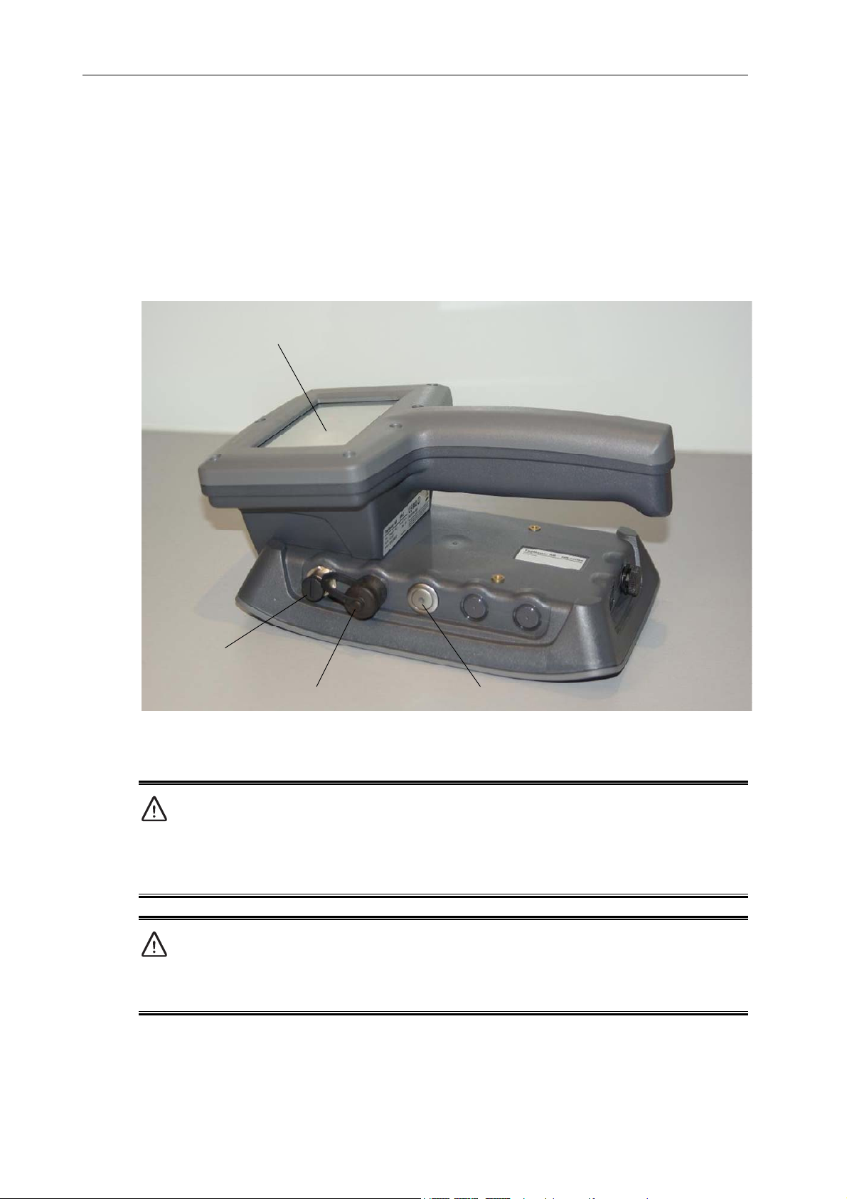
To start the HR-2 reader, press the power switch button (see Figure 3). When the unit
is powered on, this will be indicated with a red LED indication in the middle of the
power switch button.
Touch Screen
Power & Service Interface
Ethernet Interface Power Switch Button
Figure 3 HR-2 reader overview.
Warning!
Never power-on the HR-2 if any signs of the unit being damaged can be observed. As
the unit contains a lithium-ion battery, this could result in an accident and potential
injury. Please contact TagMaster for advice on how to proceed if the unit is damaged.
Caution!
Never exceed the environmental and electrical limits as specified in paragraph 7.
Exceeding the limits can result in permanent damage to the reader.
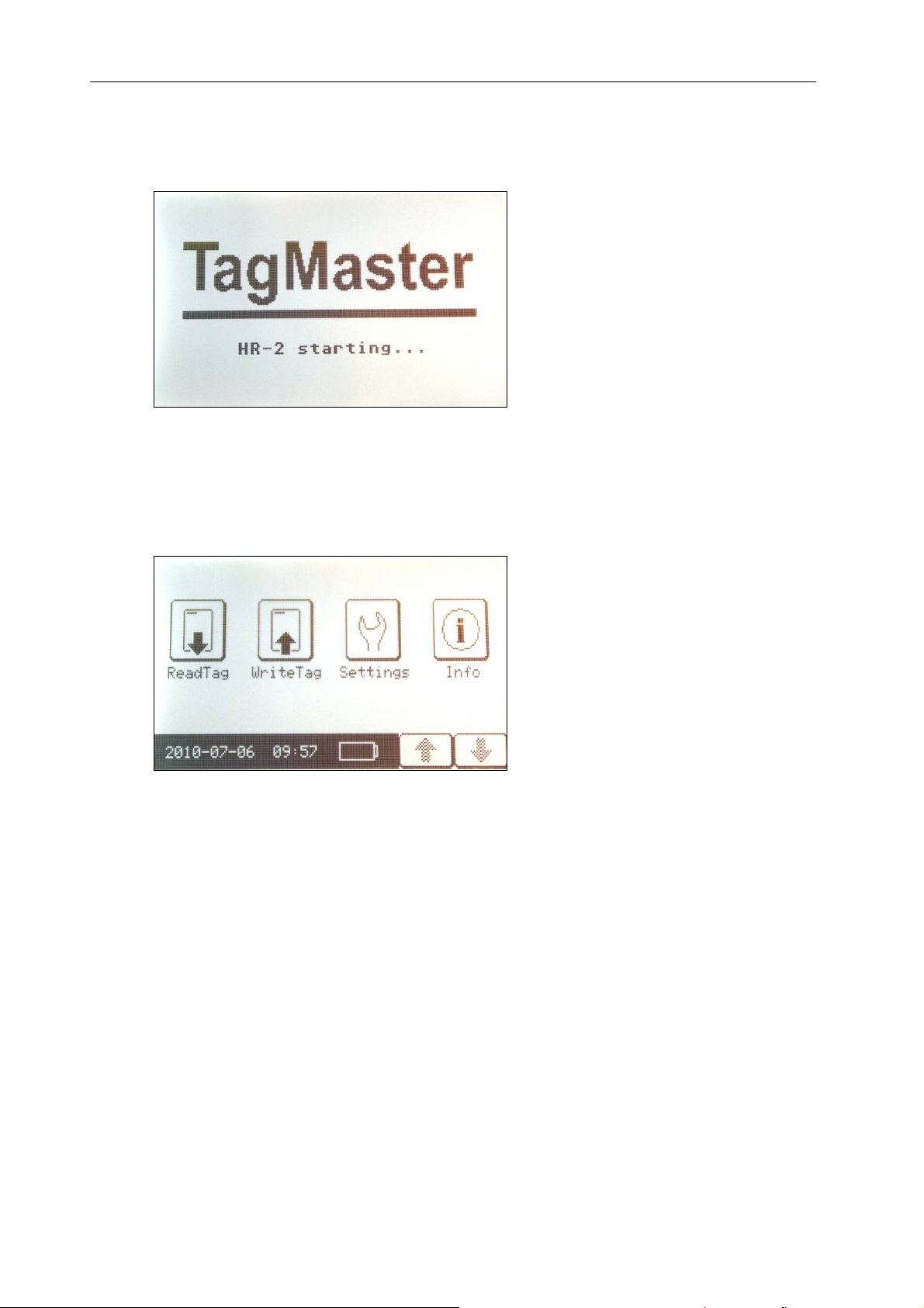
As soon as the power switch button has been pressed the boot procedure of the HR-2
will start. During this stage a boot screen will be displayed (see Figure 4). The boot
© TagMaster AB 8 (21)
Page 9
HR-2 Reader User’s Manual Doc no. 10-233 01
duration is approximately 15 seconds, but will be depending on software version and
possible specific software additions.
Figure 4 Start-up screen.
4.2 Main Menu
The main menu (see Figure 5) of the HR-2 will display a number of icons. These
include ‘ReadTag’, ‘WriteTag’, ‘Settings’ and ‘Info’. Additional Icons might be present if
optional software has been ordered from TagMaster or developed by the user.
Figure 5 Main menu screen.
The bottom of the main menu screen also displays date, time and remaining battery
capacity.
A number of general ways to interact with the HR-2 are listed below:
The vertical arrows (↑↓) at the bottom of the screen can be used to navigate (if
not all info can be displayed at once). If all info is present on the screen, these
arrows will be shaded.
The horizontal arrow (←) is being used to go back to the next higher level of the
menu hierarchy.
By touching the screen (using the tip of a finger is recommended but a stylus
can also be used) a specific alternative is activated.
© TagMaster AB 9 (21)
Page 10
HR-2 Reader User’s Manual Doc no. 10-233 01
Caution!
Never use a sharp or metal object when touching the screen. This will lead to
permanent scratches on the screen. Always us a finger (or a plastic stylus) when
interacting with the touch screen.
The HR-2 touch screen includes a function for backlight. In general, the screen
backlight will be on for a few seconds after the last user interaction. To save power, the
backlight will then fade away. To activate the backlight again touch the screen. This
single action of touching the screen to activate the backlight will not be used as input to
any of the HR-2 menus.
4.3 ReadTag Menu
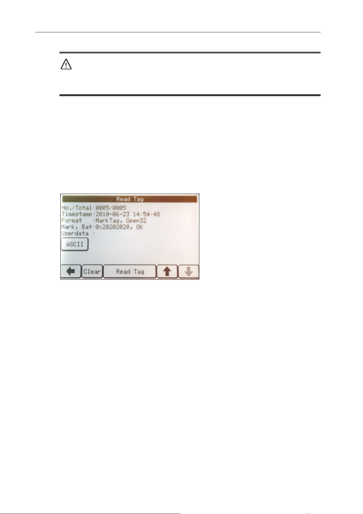
To read an ID-tag, touch the ‘ReadTag’ icon to enter the ‘ReadTag’ menu (see Figure
6).
Figure 6 ‘ReadTag’ screen.
Hold the HR-2 reader over the tag to be read. By touching ‘Read Tag’, the reader starts
searching for a tag. It will continue to search until a tag is found or an abort is issued by
the user. If a tag is found, corresponding info will be presented on the screen.
A log of all read tags will be present, and this log can be navigated using the vertical
arrows. This log can be cleared by touching ‘Clear’.
The info on ‘Read Tag’ screen is explained below:
No./Total: The record number of the displayed tag reading / the total number of
stored tag readings.
Timestamp: Timestamp of displayed tag reading.
Format: Tag type and formatting of displayed tag reading.
Mark, Bat: Info on mark and battery status of displayed tag reading.
Userdata: Info on userdata (ScriptTag only) of displayed tag reading.
The user data formatting can be changed by touching the area just below the word
Userdata.
© TagMaster AB 10 (21)
Page 11
HR-2 Reader User’s Manual Doc no. 10-233 01
4.4 WriteTag Menu
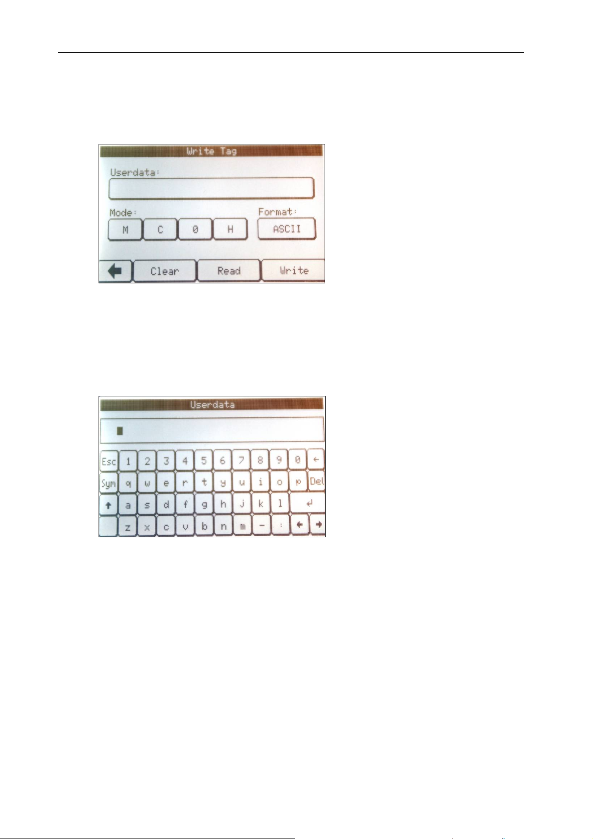
To write an ID-tag, touch the ‘WriteTag’ icon to enter the ‘WriteTag’ menu (see Figure
7).
Figure 7 ‘WriteTag’ screen.
Alternatives for selecting different ScriptTag modes (see corresponding Data Sheet for
more info) and formatting can be made. By using ‘Clear’, ‘Read’ and ‘Write’ the
corresponding actions can be carried out.
By selecting the ‘Userdata’ area, a submenu can be accessed (see Figure 8) which can
be used for entering userdata.
Figure 8 Userdata entry screen.
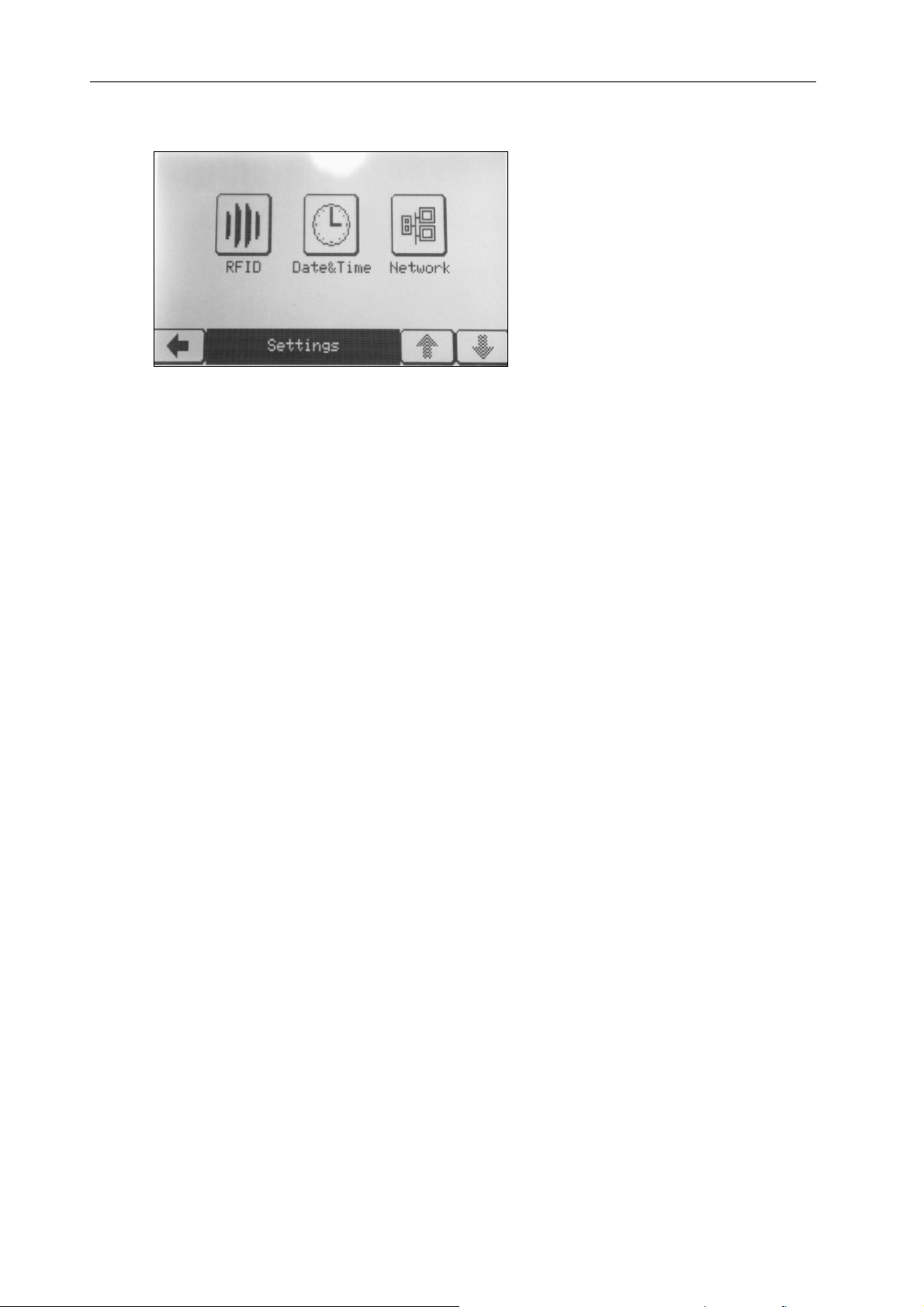
4.5 Settings Menu
The settings menu (see Figure 9) allows the user to change a number of reader
parameters.
© TagMaster AB 11 (21)
Page 12
HR-2 Reader User’s Manual Doc no. 10-233 01
Figure 9 Settings screen.
Settings that can be adjusted include:
RFID:
FHSS
Frequency
Read level
Bit rate
Date & Time:
Time zone
NTP
Date
Time
Network:
DHCP
Bonjour
Host name
IP address
Netmask
Gateway
Primary DNS
Secondary DNS
© TagMaster AB 12 (21)
Page 13
HR-2 Reader User’s Manual Doc no. 10-233 01
4.6 Info Menu
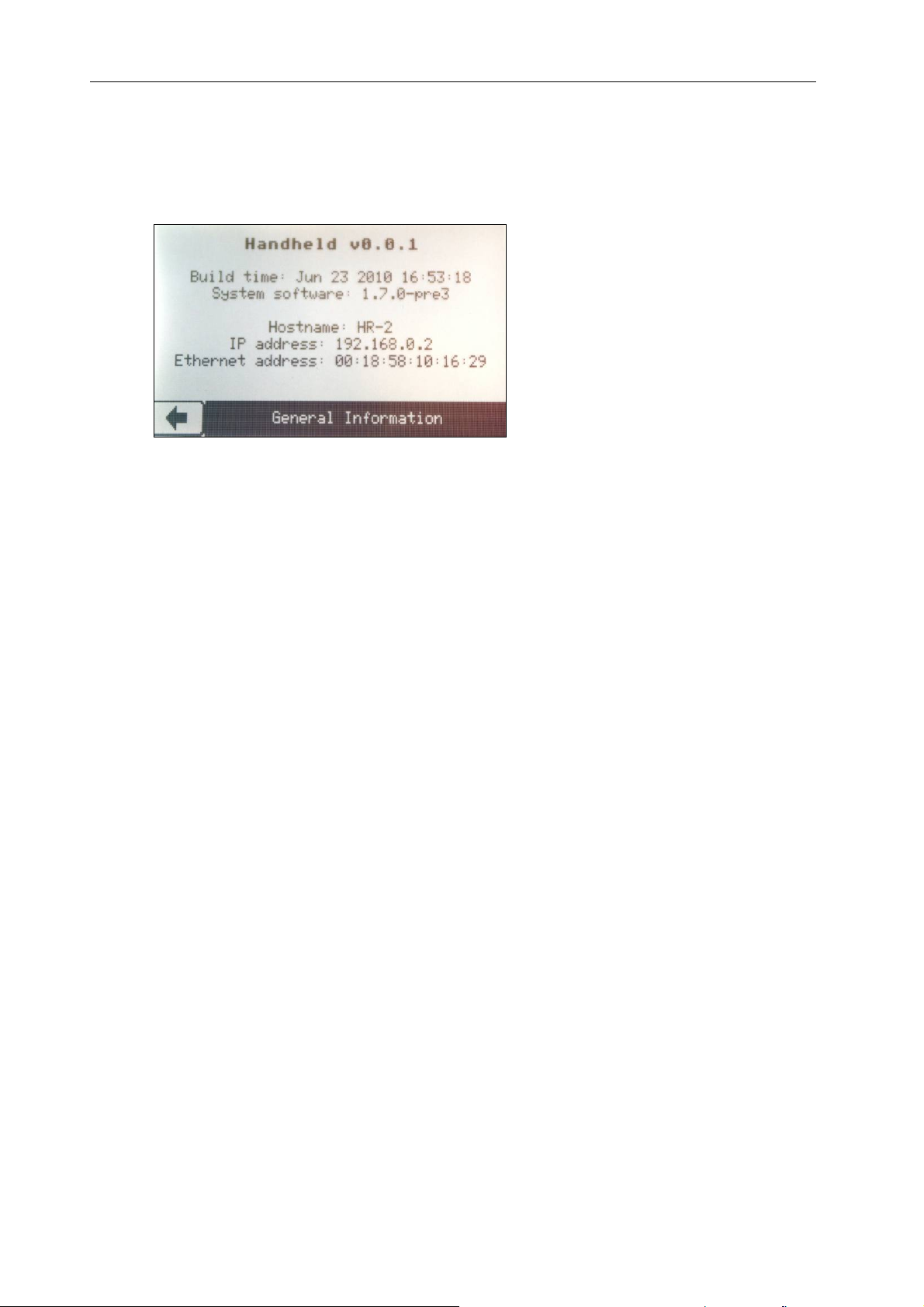
To get info on the HR-2 software and network settings, touch the ‘Info’ icon to enter the
‘Info’ menu (see Figure 10).
Figure 10 ‘Info’ screen.
© TagMaster AB 13 (21)
Page 14

HR-2 Reader User’s Manual Doc no. 10-233 01
5 External Interfaces
5.1 Ethernet Interface
The HR-2 reader is equipped with an Ethernet Interface accessible using a M12
Ethernet connector (see Figure 2). For convenience a short cable converting the M12
Ethernet to RJ45 is included with the HR-2.
The Ethernet interface can be used for uploading log files and adjusting the settings of
the HR-2. All settings available using the touch screen can also be adjusted using the
web server of the reader.
5.2 Service Interface
The HR-2 reader is equipped with a combined Power & Service Interface (see Figure
3). The service interface is providing a text-based way to configure the reader. A PC
with terminal emulation software is used to access the administration interface.
Perform the configuration as follows:
1. Connect the Service Interface of the reader to the serial port of a PC with a
RS232.
2. Configure the terminal emulator with the following communication settings:
• Baud rate: 115200
• Data bits: 8
• Parity: None
• Stop bits: 1
• Flow control: None
• Emulation: VT100
3. Open a connection from the terminal emulator to the reader and press ENTER.
The login prompt will be displayed.
4. Login as user admin. The default password is qwerty.
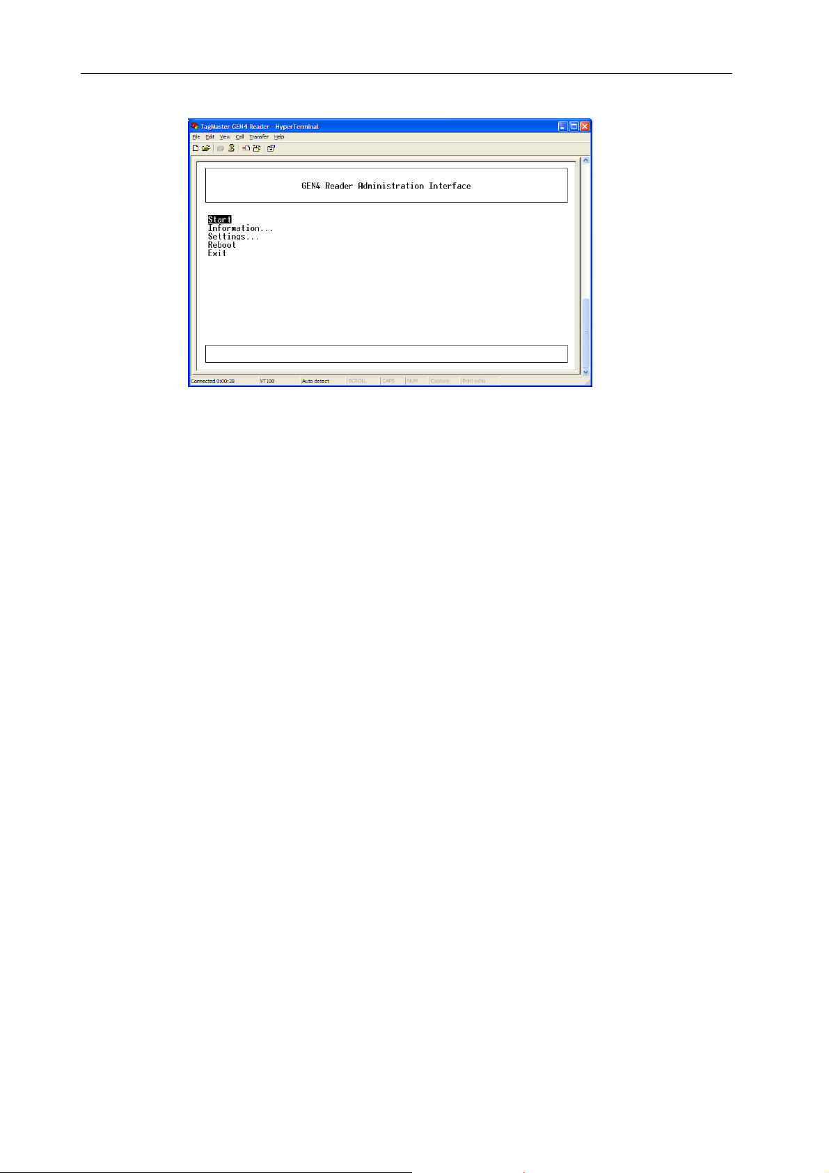
5. The main menu will be displayed with the following menu items:
• Start TagMaster contact information
• Information Detailed system information (HW/SW versions, etc.)
• Settings Settings menu
• Reboot Reboots the reader
• Exit Exits the administration interface
© TagMaster AB 14 (21)
Page 15
HR-2 Reader User’s Manual Doc no. 10-233 01
Figure 11 Service interface main menu.
© TagMaster AB 15 (21)
Page 16
HR-2 Reader User’s Manual Doc no. 10-233 01
6 Charging the Unit
The HR-2 is equipped with an internal lithium-ion battery. When the HR-2 is running
low on power, this will be indicated by the battery status icon on the main menu (see
Figure 5 ).To start recharging, connect the HR-2 charger (included with the unit) to the
Power and Service Interface M12 connector (see Figure 3). Only the original HR-2
charger may be used together with the unit, and the specific M12 connector is chosen
to make a mix-up highly unlikely. If the HR-2 charger is lost or broken, contact
TagMaster for a replacement charger.
A full recharge takes 5 hours to complete (given that the HR-2 is powered off during
this time).
The HR-2 battery and charging electronics has been designed and reviewed to fulfil
relevant safety requirements. For this reason the battery may not be replaced or the
HR-2 unit modified in any way. If a change of battery is need, return the unit to
TagMaster for service.
Warning!
The HR-2 may only be charged in the temperature interval of 0°C to 50°C. Charging the
HR-2 outside this specified temperature interval may cause injury.
Warning!
Incinerate, disassemble, short circuit, dispose of in fire, or heat above 60°C/140°F may
cause burst or burn. Use designated charger only.
© TagMaster AB 16 (21)
Page 17
HR-2 Reader User’s Manual Doc no. 10-233 01
7 Technical Data
7.1 Reader Overview
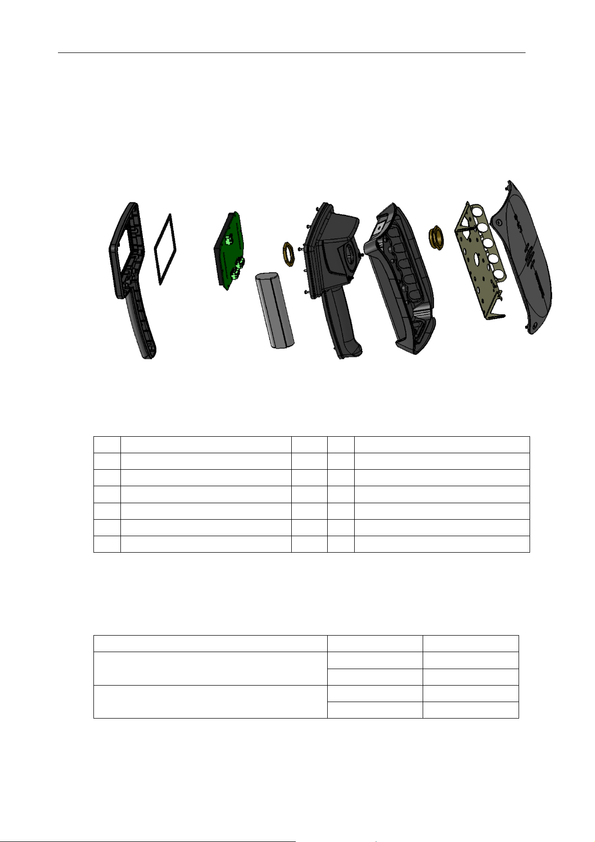
Figure 12 shows an overview of the internals of HR-2 reader.
1 3 4
7 9 10 11 12
6
5
8
2
Figure 12 Overview of the HR-2 reader.
The following table describes the position of the components inside the unit.
No Component
Top
1
Gasket
2
LCD gasket and cover film
3
Screen module
4
Li-Ion battery pack
5
Barrier nut
6
7
8
9
10
11
12
No Component
Bottom
Gasket
Enclosure Base
Reduction Nipple
Shield Plate
Lid
Table 1 Components of the HR-2.
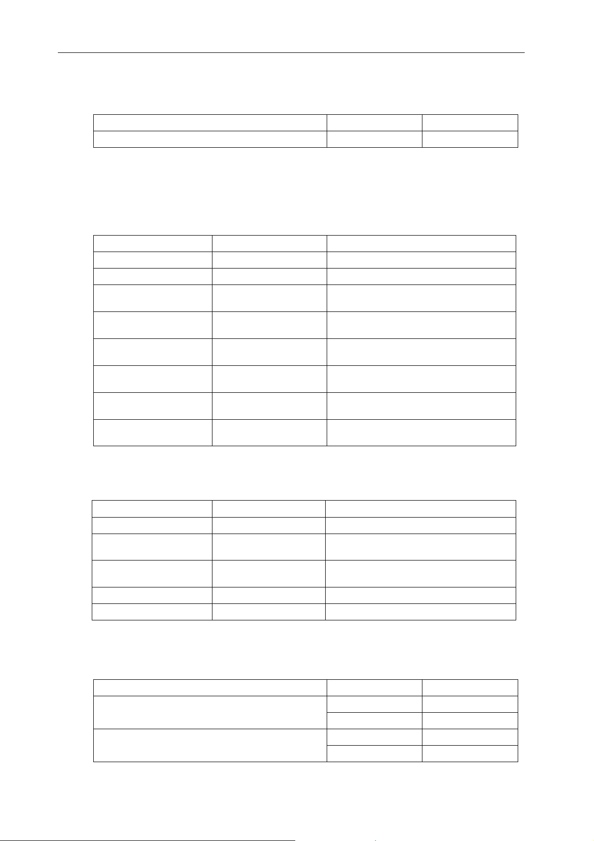
7.2 Performance Data
7.2.1 Communication range data
Parameter Value Unit
Read Range
* Default setting is 2m/6.6 ft, which can be easily adjusted using the configuration menu
© TagMaster AB 17 (21)
Up to 3.5* m
Up to 11.5* ft
Up to 0.2 m Write Range
Up to 0.6 ft
Page 18
HR-2 Reader User’s Manual Doc no. 10-233 01
7.2.2 RFID communication speed
Parameter Value Unit
Data Speed 16 kb/s
7.3 Electrical Data
Data regards the temperature range −20°C to +45°C or −4 to +113 °F.
7.3.1 Radio
Parameter Value Unit
Radio Wave Polarisation Circular
Output Power 10 mW e.i.r.p
CW-mode: Radiation
Frequency
CW-mode: Number of RF
Channels
CW-mode: Channel
Separation
FHSS-mode*: Radiation
Frequency
FHSS-mode*: Number of
RF Channels
FHSS-mode*: Channel
Separation
* Not available in Japan, Korea and Taiwan.
2435–2465 MHz
93
300 KHz
2400–2483.5 MHz
400
200 KHz
7.3.2 Power supply
Parameter Value Unit
DC battery Charger* 24 VDC
DC Power Consumption
Typical
Max DC Power
Consumption
Internal battery voltage 14.4 VDC
Internal battery capacity 2200 mAh
4.5 W
15 W
* 100- 240 VAC powered battery charger (24V, Max 2A) included with reader
7.4 Mechanical Data
Parameter Value Unit
Weight
Dimensions
1.4 kg
3.1 lbs
257×154×142 mm
10.12 × 6.06 × 5.59 in
© TagMaster AB 18 (21)
Page 19
HR-2 Reader User’s Manual Doc no. 10-233 01
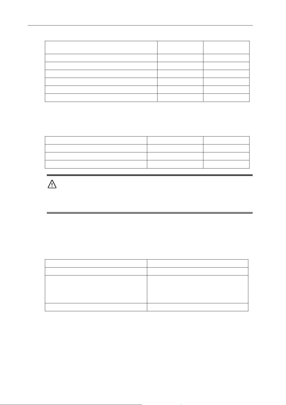
Enclosure Material PC-PBT and PC
(Xenoy)
Chassis Material Aluminium
Sealing Rubber Gaskets
Colour: Enclosure base & bottom Dark Grey RAL7024
Colour: Lid & top Light Grey RAL7001
Power and Service Interface connector M12 × 5 Poles
Ethernet connector M12 x 4 Poles
7.5 Environmental Specification
7.5.1 Climate
Parameter Value Reference
Cold −20°C or −4°F -
Heat +60°C or +140°F -
Sealing IP54
Caution!
Do not remove the pressure balance membrane, or use the unit without protective caps on
the Power & Service Interface or Ethernet Interface. This will compromise the IP
classification.
7.5.2 RoHS
The HR-2 reader complies with RoHS Directive 2002/95/EC
7.5.3 Electrical
Parameter Reference
Immunity Acc. to CE: EN 301 489-3
Emission Acc. To:
CE: EN 300 440-2 (radio) and EN 301 489-3
(EMC).
FCC part 15 subpart B and C. The Reader fulfils
Class B digital equipment limits
Safety EN 60 950-1
NOTE: This equipment has been tested and found to comply with the limits for a Class A digital device,
pursuant to part 15 of the FCC Rules. These limits are designed to provide reasonable protection against
harmful interference when the equipment is operated in a commercial environment. This equipment
generates, uses, and can radiate radio frequency energy and, if not installed and used in accordance with
the instruction manual, may cause harmful interference to radio communications. Operation of this
equipment in a residential area is likely to cause harmful interference in which case the user will be
required to correct the interference at his own expense.
© TagMaster AB 19 (21)
Page 20

HR-2 Reader User’s Manual Doc no. 10-233 01
Caution
Information to user: Changes or modifications not expressly approved by the party responsible for
compliance could void the user’s authority to operate the equipment.
© TagMaster AB 20 (21)
Page 21

HR-2 Reader User’s Manual Doc no. 10-233 01
8 Contact
For any further inquiries, please contact TagMaster AB.
8.1 Technical Support
Phone: + 46 8 632 19 50
Fax: +46 8 750 53 62
E-mail: [email protected]
8.2 Office
TagMaster AB
Kronborgsgränd 1
S-164 87 KISTA, Sweden
Phone: +46 8 632 19 50
Fax: +46 8 750 53 62
E-mail: [email protected]
Web: www.tagmaster.com
© TagMaster AB 21 (21)
 Loading...