


Switching Power Supply User Manual
ATX12V / EPS12V Power Supply
TG-I460R (460W+460W)
TG-I550R (550W+550W)
User Manual
Mini Redundant Series User Manual
Revision: 1.0

Switching Power Supply User Manual
Table of Contents
1 Introduction
2 General specification
3 Installation
4 Pin assignment & function of connectors
5 Drawing
Warranty
3 (Three) years manufacture’s warranty. Date code indicating week
and year of manufacture
All brand names and trademarks are the property of their
All above specifications are subject to change without prior
Mini Redundant Series User Manual
Revision: 1.0
respective owners.
notice!

Switching Power Supply User Manual
Introduction
The TG-I460R & TG-I550R series (Mini Redundant Power Supply)
Switching Mode Power Supply is compliant with the latest
EPS12V Ver. 2.9 and ATX12V Ver. 2.2. The TG-I460R &
TG-I550R, high reliability power supplies are designed for 4U
rackmount server and server tower. These high-density units
meet the electrical and mechanical requirements and diversified
into various applications.
Features
Universal AC input power
With active power factor correction (PFC)
Protection circuits designed-in
Meet EPS12V Ver. 2.9 and ATX12V Ver. 2.2 specification
Backward compatibility, -5V available
Industrial DIN-connector for reliability
Automatic thermal control (Fan speed control)
PS2 size with redundant configuration
Standard PC connection / wiring interface
Hot-Swap / Hot-Plug application
Power failure alarm & signals
MTBF (Demonstrated) greater than 100,000 hours
3 years warranty
Mini Redundant Series User Manual
Revision: 1.0

Switching Power Supply User Manual
Max.
2. Specification
2.1 The range of AC input voltage
100-240 VAC with active Power Factor Correction (PFC)
2.2 DC output characteristics
During operation the maximum load shall not be exceeded
460 / 550 Watts.
The total load on +5V and +3.3V shall not be exceeded 180
watts for 550W and 220 watts for 460W.
Voltage / Function Min Current
460W+460
W
Current
550W+550
W Max.
Current
+5VDC 0A 35A 30A
+3.3VDC 0A 22A 24A
+12VDC 0A 32A 41A
-5VDC 0A 0.5A 0.5A
-12VDC 0A 1A 1A
5VSB 0.1A 2A 2A
2.3 Operating Environment
Maximum operating temperature is 40 ºC
Maximum operating Humidity is 90% RH
2.3 LED Instructions
There is a LED indicated power supply’s status within Module’s
front panel.
Power Status LED Color
Stand by Amber
Power ON Green
Power Fault Red
Configure 2-1: LED Instructions
Mini Redundant Series User Manual
Revision: 1.0
Switching Power Supply User Manual
Black
Description and Illustration for Connectors:
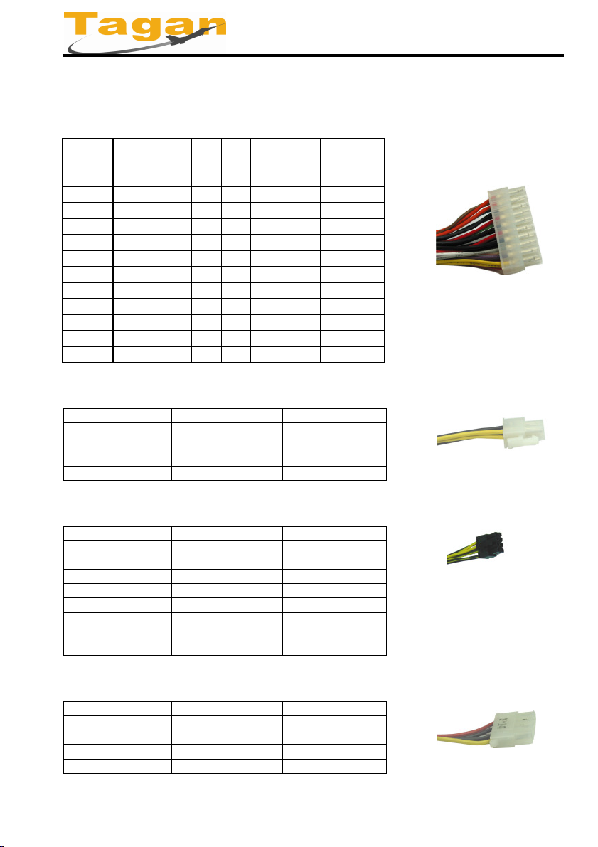
a. ATX12V 24Pin Main Power Connector
Color Signal Pin Pin Signal Color
Orange
BRN.
Blue -12VDC 14 2 +3.3VDC Orange
Black COM 15 3 COM Black
Green PS-ON 16 4 +5VDC Red
Black COM 18 6 +5VDC Red
Black COM 19 7 COM Black
White -5VDC 20 8 PG Gray
Red
Red +5VDC 22 10 +12VDC Yellow
Red +5VDC 23 11 +12VDC Yellow
Black COM 24 12 +3.3VDC Orange
b. P4 optional +12V connector (4 Pin)
Color Signal Pin
Black COM 1
Black COM 2
Yellow +12VDC 3
Yellow +12VDC 4
c. EPS +12V connector (8Pin)
Color Signal Pin
Black COM 1
Black COM 2
Black COM 3
Black COM 4
Yellow +12VDC 5
Yellow +12VDC 6
Yellow +12VDC 7
Yellow +12VDC 8
d. (HDD) Drive connector (4 Pin)
Color Signal Pin
Yellow +12VDC 1
Black COM 2
Black COM 3
Red +5VDC 4
+3.3VDC
+3.3VS
COM 17 5 COM Black
+5VDC/+5VS
13
1
13
21 9 +5VSB Purple
+3.3VDC Orange
Mini Redundant Series User Manual
Revision: 1.0
Switching Power Supply User Manual
e. (FDD) Floppy connector (4 Pin)
Color Signal Pin
Yellow +12VDC 1
Black COM 2
Black COM 3
Red +5VDC 4
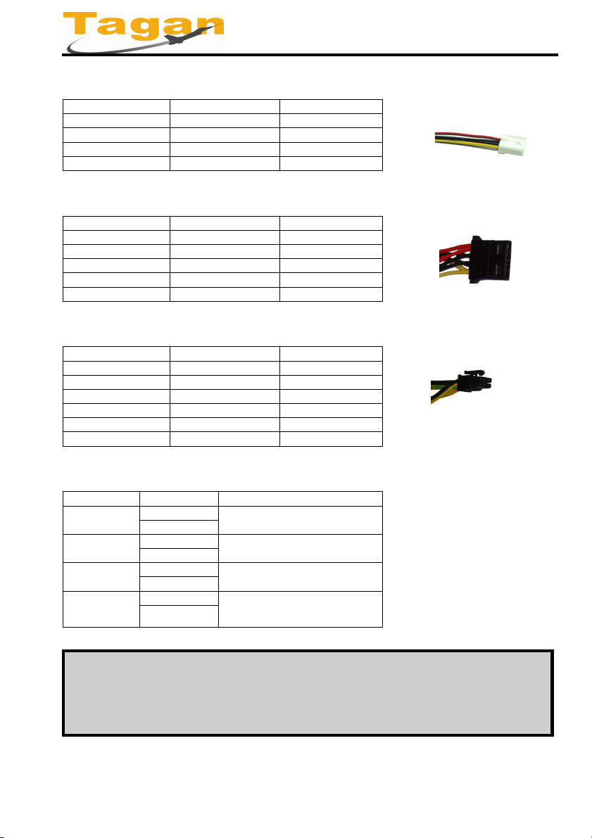
f. SATA connector (5 Pin)
Color Signal Pin
Yellow +12VDC 1
Black COM 2
Red +5VDC 3
Black COM 4
Orange +3.3VDC 5
g. PCI-E connector (6 Pin)
Color Signal Pin
Yellow +12VDC 1
Yellow +12VDC 2
Yellow +12VDC 3
Black COM 4
Black COM 5
Black COM 6
g. Signal cable connector (2 Pin)
Signal Type Color Description
Total PFD
PW1 PFD
PW2 PFD
Alarm Reset
Orange Power Failure Detection for
Black
Blue Power Dailure Detection for
Black
Yellow Power Dailure Detection for
Black
White
Black
power modules, TTL Signal
Module 1, TTL Signal
Module 2, TTL Signal
Short can cancel the buzzer for
alarm, sam as Front panel reset
SW
WARNING:
Please turn off the main on/off switch and do not plug the
individual power supplies’ input cables before install the power
Mini Redundant Series User Manual
Revision: 1.0
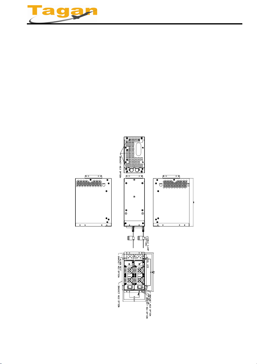
Installation
Switching Power Supply User Manual
Firstly, make sure that your computer is turned off when you are
fitting this power supply into an existing system, and then remove
the main power cord. Open the case of your PC; remove all
connectors from the drive and motherboard. Release the four
screws and remove the old power supply.
Place the power supply in the case and fix it with four screws.
Connect all drives and the motherboard to power supply.
(Describing as “Descriptions and illustration connectors”) and make
sure that the push button in the case is connected to the
motherboard.
Mini Redundant Series User Manual
Revision: 1.0
 Loading...