

Page 1
TAG
22355 TAG Way
Dulles, VA 20166
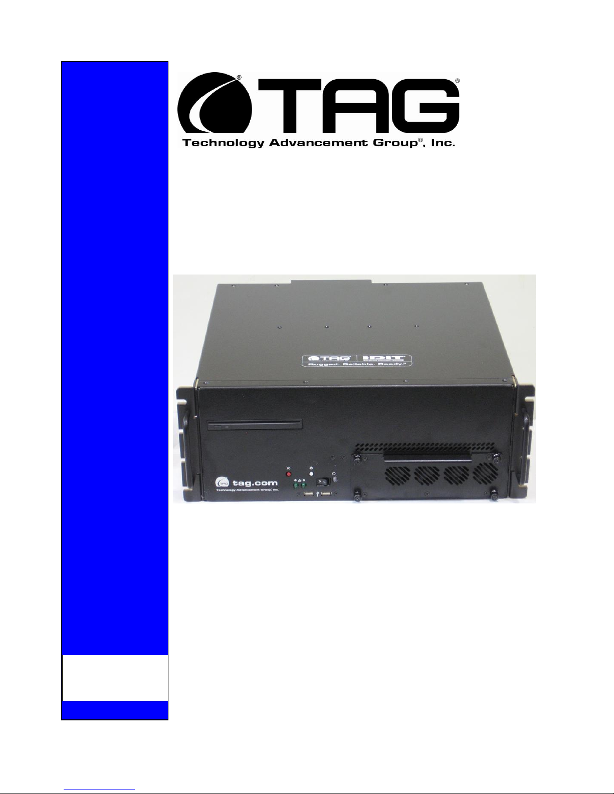
4U Quad Core Xeon Server
SV-4002-X2
Operations Manual
Page 2

Operations Manual
1 Copyright © 2008 Technology Advancement Group®, Inc.
(TAG®)
All rights reserved. This publication and its contents are proprietary to TAG. No part of
this publication may be reproduced in any form or by any means without the written
permission of TAG, 22355 TAG Way, Dulles, Virginia 20166-9310.
TAG has made every effort to ensure the correctness and completeness of the material
in this document. TAG shall not be liable for errors contained herein. The information in
this document is subject to change without notice. TAG makes no warranty of any kind
with regard to this material, including, but not limited to, the implied warranties of
merchantability and fitness for a particular purpose.
1.1 Trademarks
All trademarks, marks, names, or product names referenced in this publication are the
property of respective owners, and TAG neither endorses nor otherwise sponsors any
such products or services referred to herein.
Part Number: 1008960 Page 2 of 54
SV-4002-X2
Version 1.0. 09/09/2010
Page 3
Operations Manual
2 About TAG
2.1 Summary of Qualifications
TAG has served as a leading provider of IT solutions to DoD customers over the past
20+ years and has a long-standing and respected history of providing Systems
Engineering, Electronic Equipment and Program Management support to US Military
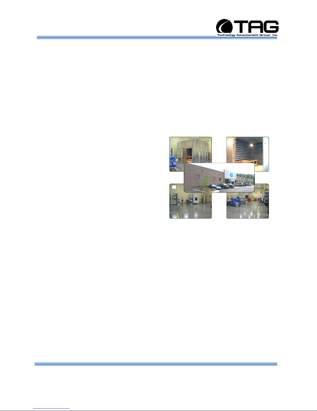
warfighters. Headquartered in Dulles, Virginia, TAG’s state-of-the-art 35,000 sq. ft.
engineering and manufacturing facility provides all the infrastructure, equipment, and
manpower necessary to engineer, design, test, manufacture, and certify products to the
rugged requirements of the tactical combat theater. Our facilities in Dulles, VA, San
Diego, CA, and St. Louis, MO, allow for rapid deployment of products and support
across the globe.
TAG quickly, efficiently, and cost-effectively tailors rugged solutions for large DoD
programs with specific MIL-STD requirements. TAG’s comprehensive Quality
Assurance (QA) policy – enforced through application of our UL-registered ISO
9001:2000 certified processes – enables TAG to rapidly deploy systems and solutions
that reliably withstand the stresses of the tactical environment. Today, there are over
20,000 TAG systems deployed across various weapons platforms throughout the US
Military. TAG effectively balances all corporate assets – our people, expertise,
infrastructure, and experience – to consistently and successfully execute and deliver to
the DoD.
TAG’s success lies in focusing on the
corporate Mission Statement and leveraging
the tenets of our business model to ensure
the customer’s expectations are exceeded
throughout lengthy program lifecycles.
TAG’s Mission is to resolve our customers’ IT
challenges with World-Class:
Engineering;
Manufacturing and Integration; and
Lifecycle Management
TAG has a proven track record in
implementing these tenets to serve as a trusted advisor to our Government customers.
TAG uses this foundation to ensure risk is mitigated, expectations are exceeded, and
the customer can consistently rely on the company, our equipment, and our services.
SV-4002-X2
Part Number: 1008960 Page 3 of 54
Version 1.0. 09/09/2010
Page 4
Operations Manual
2.2 Core Competences
2.2.1 Engineering
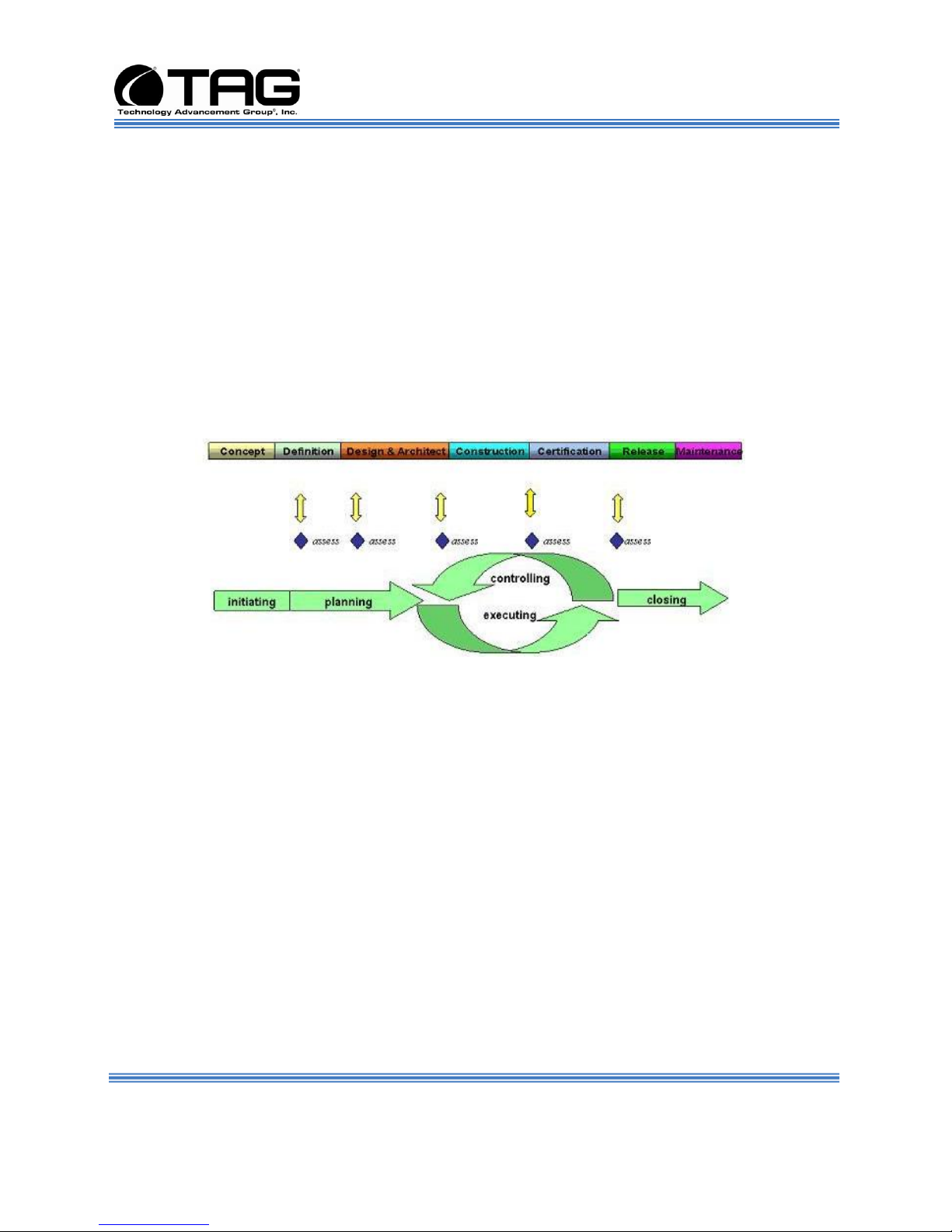
TAG’s engineering methodology is built upon Multi-Disciplinary Optimization (MDO) and
rigorous design reviews. Although PMs drive the schedule at TAG, Engineering
leverages Computer-Aided Design (CAD) tools, Computational Fluid Dynamics (CFD)
modeling, rapid prototyping processes, and diverse test equipment and facilities to
ensure requirements are being met at every step of the design. TAG Engineering
follows a proven design-review process, ensuring all entrance and exit criteria are met
at each stage. Rigorous documentation is compiled to demonstrate requirement
compliance, risks are mitigated, and decisions are prudent – throughout the design
process.
TAG prides itself on its engineering
laboratories and facilities. Over the past
three years, TAG has invested in several
pieces of equipment that allow TAG to test
and certify products directly onsite to the
harshest environmental requirements of
military standards – including the MIL-STD810F and DO 160D.
TAG’s onsite test equipment currently
includes a Highly Accelerated Lifecycle
Testing (HALT) Chamber, an
Electromagnetic Interference (EMI) test chamber, and a high-/low-temperature thermal
test chamber. TAG’s facility also provides:
A floor plan designed to support a cellular manufacturing model with modular
assembly lines
A dedicated 24-hour system burn-in room
A modern production status tracking and Enterprise Resource Planning (ERP)
system with external web collaboration capabilities
Dedicated Quality Assurance workstations for system compliance and validation
inspection
2.2.2 Manufacturing and Integration
TAG implements Cellular Manufacturing processes through our compartmentalized,
state-of-the-art production facility to minimize waste byproducts and maximize
production efficiency. TAG’s manufacturing facility is physically partitioned to model the
major philosophies of Lean Manufacturing. Consistent with the model, each of TAG’s
production cells are capable of operating in isolation; however personnel and tools are
Part Number: 1008960 Page 4 of 54
SV-4002-X2
Version 1.0. 09/09/2010
Page 5
Operations Manual
shared across all cells to streamline manufacturing operations, costs, and the
production/integration scheduling. TAG’s floor technicians are cross-trained in multiple
disciplines so they can be redistributed to any cell that encounters production
bottlenecks, which ensures optimal efficiency.
2.2.3 Lifecycle Management
TAG’s world-class Program Management discipline models the renowned
methodologies of the Project Management Institute (PMI) to ensure successful
completion of the task at hand. Our Program Managers (PMs) serve as the voice of the
customer – driving requirements to which the rest of TAG’s organization answers. As
an explicit tenet of TAG’s corporate mission statement, the PMs not only track cost,
schedule, and technical compliance throughout a project’s period of performance, but
also ensure the customer is supported well beyond it.
SV-4002-X2
Part Number: 1008960 Page 5 of 54
Version 1.0. 09/09/2010
Page 6

Date
Version
Number
Updated By
Description of
Changes
09/09/2010
1.0
Alan Huckerby
Author
Operations Manual
Document Revision History
Part Number: 1008960 Page 6 of 54
SV-4002-X2
Version 1.0. 09/09/2010
Page 7

Operations Manual
3 About This Manual
3.1 Scope and Audience
This Manual provides an introductory overview
of the SV-4002-X2. Designed to endure the
rigors of harsh environments, this device can
withstand shock and vibration, high and low
temperatures. All of our devices are based on
the latest Intel and AMD technology. Also, this
device doesn't use Intel Core Due or Pentium
M technology (only THS servers).
. Configuration options include extended
memory and enhanced video optimization. All
of our servers are backed by our world-class
lifecycle management and post sales support.
3.1.1 Organization:
Chapter 1 Provides Cautions and Warnings.
Chapter 2 Provides operational information.
Chapter 3 Contains all relevant Procedures.
Appendix CDW.
This manual is divided into the following
chapters:
Part Number: 1008960 Page 7 of 54
SV-4002-X2
Version 1.0. 09/09/2010
Page 8

Operations Manual
Table of Contents
Contents
1 Copyright © 2008 Technology Advancement Group®, Inc. (TAG®) ............................ 2
1.1 Trademarks ............................................................................................................ 2
2 About TAG ................................................................................................................... 3
2.1 Summary of Qualifications ...................................................................................... 3
2.2 Core Competences ................................................................................................. 4
2.2.1 Engineering ....................................................................................................... 4
2.2.2 Manufacturing and Integration ........................................................................... 4
2.2.3 Lifecycle Management ...................................................................................... 5
3 About This Manual ....................................................................................................... 7
3.1 Scope and Audience .............................................................................................. 7
3.1.1 Organization: ..................................................................................................... 7
4 Safety Instructions ....................................................................................................... 12
4.1 Types of Warnings used in this Manual .................................................................. 12
4.1.1 Safety Symbols and Labels ............................................................................... 12
4.1.2 Conventions ...................................................................................................... 12
5 SV-4002-X2 Overview ................................................................................................. 15
5.1 Product Information ................................................................................................ 15
5.2 SV-4002-X2 ............................................................................................................ 16
5.2.1 SV-4002-X2” Specifications .............................................................................. 17
5.2.2 SV-4002-X2 Components ................................................................................. 17
5.2.3 Server Board ..................................................................................................... 19
5.2.4 Server Board Feature Location ................................................................ ......... 22
5.3 Host Bus Adapter ................................................................................................... 23
5.3.1 Hot Bus Adapter Specifications ......................................................................... 23
5.4 Power Management ............................................................................................... 25
5.4.1 Power Supply .................................................................................................... 25
5.4.2 Power Supply Components ............................................................................... 25
6 Procedures .................................................................................................................. 28
6.1 SV-4002-X2 Startup ............................................................................................... 28
6.2 SV-4002-X2 Shutdown ........................................................................................... 28
7 Identifying Server Components Using Device Manager ............................................... 29
7.1 Working with Device Properties .............................................................................. 32
7.2 Installing and Removing Hardware in Windows...................................................... 34
7.2.1 Using the Add New Hardware Wizard ............................................................... 35
7.3 Installing Legacy Peripherals .................................................................................. 36
7.3.1 Removing Legacy Peripherals .......................................................................... 36
7.4 TAG Approved BIOS .............................................................................................. 40
7.4.1 BIOS Configuration for SV-4002-IX ................................................................... 41
8 APPENDIX CDW ......................................................................................................... 52
SV-4002-X2
Part Number: 1008960 Page 8 of 54
Version 1.0. 09/09/2010
Page 9

Operations Manual
List of Figures
Figure 5-1 SV-4002-X2 ................................................................................................. 15
Figure 5-2 SV-4002-X2 (Front View) ............................................................................. 16
Figure 5-3 SV-4002-X2 (Rear View).............................................................................. 16
Figure 5-4 Server Board. ............................................................................................... 20
Figure 5-5 Server Board Layout .................................................................................... 21
Figure 7-1 Control Panel. .............................................................................................. 29
Figure 7-2 System Properties. ....................................................................................... 30
Figure 7-3 Device Manger ............................................................................................. 30
Figure 7-4 Device Manager ........................................................................................... 32
Figure 7-5 Properties Dialog Box .................................................................................. 33
Figure 7-6 Control Panel. .............................................................................................. 35
Figure 7-7 Add Hardware Wizard .................................................................................. 36
Figure 7-8 Control Panel. .............................................................................................. 37
Figure 7-9 System Properties. ....................................................................................... 38
Figure 7-10 Device Manager. ........................................................................................ 38
Figure 7-11 BIOS Setup. ............................................................................................... 41
Figure 7-12 Quiet Boot Disable Screen. ........................................................................ 41
Figure 7-13 Main Page Screen. .................................................................................... 42
Figure 7-14 Advanced Feature Screen. ........................................................................ 42
Figure 7-15 Delay Prior to Thermal. ................................ .............................................. 43
Figure 7-16 Advanced BIOS Features Screen. ............................................................. 43
Figure 7-17 Advance Screen. ........................................................................................ 44
Figure 7-18 ATA Controller Configuration Screen. ........................................................ 44
Figure 7-19 Serial Port Configuration Screen. ............................................................... 45
Figure 7-20 Serial Port Configuration Screen. ............................................................... 45
Figure 7-21 USB Configuration Screen. ........................................................................ 46
Figure 7-22 USB Configuration Screen. ........................................................................ 46
Figure 7-23 PCI Configuration Screen. ......................................................................... 47
Figure 7-24 System Acoustic and Performance Configuration Screen.......................... 47
Figure 7-25 Integrated Peripherals Screen. .................................................................. 48
Figure 7-26 Onboard Device Screen. ............................................................................ 48
Figure 7-27 Boot Options Screen. ................................................................................. 49
Figure 7-28 Integrated Peripherals Screen. .................................................................. 49
Figure 7-29 IPO INTEL SSDSA2M040G2GC Screen. .................................................. 50
Figure 7-30 Boot Manager Screen. ................................................................ ............... 50
Figure 7-31 Save and Reset Popup Menu Screen. ....................................................... 51
Figure 8-1 CDW ASSY-4U X2 ....................................................................................... 53
Table 5-1 Server Board Features (1)............................................................................. 19
Table 5-2 Server Board Features (2)............................................................................. 20
Part Number: 1008960 Page 9 of 54
List of Tables
SV-4002-X2
Version 1.0. 09/09/2010
Page 10

Operations Manual
Table 5-3 Server Board Feature Location. .................................................................... 22
Part Number: 1008960 Page 10 of 54
SV-4002-X2
Version 1.0. 09/09/2010
Page 11

Operations Manual
Chapter 1
Cautions and Warnings.
Electronically distributed. Subject to user discretion when printed.
Part Number: 1008960 Page 11 of 54
SV-4002-X2
Version 1.0. 09/09/2010
Page 12
DANGER
WARNING
CAUTION
These warnings and
cautions indicate situations
or practice that might
result in property damage.
Operations Manual
4 Safety Instructions
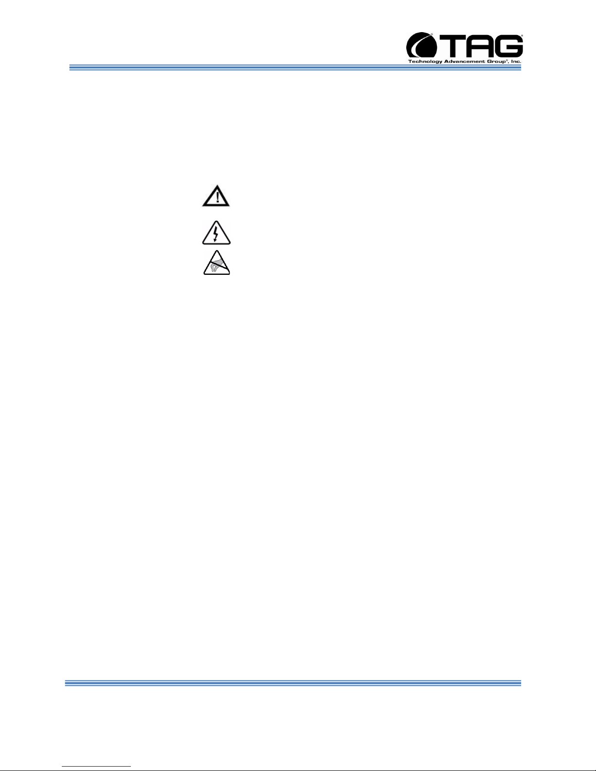
4.1 Types of Warnings used in this Manual
Read this manual thoroughly, paying special attention to the cautions and warnings.
4.1.1 Safety Symbols and Labels
4.1.2 Conventions
4.1.2.1 Important Messages
4.1.2.2 Warnings
Important messages appear where
mishandling of components is possible or when
work orders can be misunderstood. These
messages also provide vital information
associated with other aspects of system
operation. The word “important” is written as
“IMPORTANT,” both capitalized and bold and
is followed by text in italics. The italicized text
is the important message.
Warnings appear where overlooked details
may cause damage to the equipment or result
in personal injury. Warnings should be taken
seriously. Warnings are easy to recognize. The
word “warning” is written as “WARNING,” both
capitalized and bold and is followed by text in
Part Number: 1008960 Page 12 of 54
SV-4002-X2
Version 1.0. 09/09/2010
Page 13

Operations Manual
italics. The italicized text is the warning
message.
4.1.2.3 Cautions
Cautionary messages should also be heeded
to help you reduce the chance of losing data or
damaging the system. Cautions are easy to
recognize. The word “caution” is written as
“CAUTION,” both capitalized and bold and is
followed by text in italics. The italicized text is the
cautionary message.
4.1.2.4 Notes
Notes inform the reader of essential but noncritical information. These messages should be
read carefully as any directions or instructions
contained therein can help you avoid making
mistakes. Notes are easy to recognize. The
word “note” is written as “NOTE,”
Part Number: 1008960 Page 13 of 54
SV-4002-X2
Version 1.0. 09/09/2010
Page 14

Operations Manual
Chapter 2
SV-4002-X2
.
Electronically distributed. Subject to user discretion when printed.
Part Number: 1008960 Page 14 of 54
SV-4002-X2
Version 1.0. 09/09/2010
Page 15

Operations Manual
5 SV-4002-X2 Overview
5.1 Product Information
Figure 5-1 SV-4002-X2
The SV-4002-X2 sets the standard for Servers
with state-of-the-art technology. The newest
Server can stand up to the harshest
environments, and is designed specifically to
be fully customized to support unique, missioncritical applications.
Your system may contain components not
described in this User Manual. For detailed
information on these components, refer to the
manufactures website or contact TAG
Technical Support at tech.support@tag.com.
Part Number: 1008960 Page 15 of 54
SV-4002-X2
Version 1.0. 09/09/2010
Page 16

Operations Manual
5.2 SV-4002-X2
Figure 5-2 SV-4002-X2 (Front View)
Figure 5-3 SV-4002-X2 (Rear View).
Part Number: 1008960 Page 16 of 54
SV-4002-X2
Version 1.0. 09/09/2010
Page 17

Operations Manual
5.2.1 SV-4002-X2” Specifications
TAG SV-4002-X2, 4U Quad Core Xeon Server
Chassis
4U Heavy-duty Aluminum rack-mount chassis.
6.97"H x 13.23"W x 17.31"L.
Hot-swap, Redundant P/Supplies
(accepts power sources world-wide).
Intelligent Fan Controller
Intel Xeon low voltage L5408 Quad Core
Processor 1
2.13GHz, 12MB cache
Intel® Server Board
Eight-Port 6Gb/s PCI Express SATA+SAS
Host Bus Adapter
4GB DDR2 RAM (8GB total)
Operating System: MS Windows Server
2003.
I/O Ports:
(2) Ethernet Ports. (Rear Panel
Accessible).
2) High-Speed 6Gb/s Ports,
(2) USB 2.0 ports. (Front Panel
Accessible).
(4) USB 2.0 ports. (Rear Panel Accessible).
(1) DB9 COMM Serial Port (Front Panel
Accessible)
PS/2 keyboard and mouse port. (Rear
Panel Accessible).
5.2.2 SV-4002-X2 Components
This section provides an overview of the most
common components installed in the SV-4002X2. Information is also provided on how to
identify specific components within your SV-
Part Number: 1008960 Page 17 of 54
SV-4002-X2
Version 1.0. 09/09/2010
Page 18

Operations Manual
4002-X2. For detailed information on the
specific components installed, refer the
manufactures websites.
Part Number: 1008960 Page 18 of 54
SV-4002-X2
Version 1.0. 09/09/2010
Page 19

Operations Manual
5.2.3 Server Board
This Server Board supports multiple
interfaces to option card slots and
devices. (Table 5-1 and Table 5-2).
Part Number: 1008960 Page 19 of 54
Table 5-1 Server Board Features (1).
SV-4002-X2
Version 1.0. 09/09/2010
Page 20

Operations Manual
Table 5-2 Server Board Features (2)
Part Number: 1008960 Page 20 of 54
Figure 5-4 Server Board.
SV-4002-X2
Version 1.0. 09/09/2010
Page 21

Operations Manual
Part Number: 1008960 Page 21 of 54
Figure 5-5 Server Board Layout
SV-4002-X2
Version 1.0. 09/09/2010
Page 22

Operations Manual
5.2.4 Server Board Feature Location
Table 5-3 Server Board Feature Location.
SV-4002-X2
Part Number: 1008960 Page 22 of 54
Version 1.0. 09/09/2010
Page 23

Operations Manual
5.3 Host Bus Adapter
The LSI SAS 9200-8e host bus adapter
enables large-scale storage arrays through
eight high-speed 6Gb/s ports, supporting up to
512 SATA and SAS physical devices. This
HBA bolsters large capacity external server
storage RAID and non-RAID enclosures by
pairing an x8 PCI Express 2.0 host interface
with two external x4 SFF8088 Mini-SAS
connectors. LSI SATA+SAS HBAs are
compatible with 6Gb/s and 3GBb/s, SATA and
SAS, hard disk drives, solid state drives, and
tape drives.
5.3.1 Hot Bus Adapter Specifications
Part Number: 1008960 Page 23 of 54
PCI Bus 8-lane, 5 GT/s PCI Express 2.0
PCI Modes Bus Master DMA
PCI Data Burst Transfer Rates Half Duplex
X8 PCIe 4000 MB/s
Full Duplex
X8 PCIe 8000 MB/s
SAS Bandwidth Half Duplex
Single Lane – 600MB/s
SV-4002-X2
Version 1.0. 09/09/2010
Page 24

Operations Manual
Wide port (2 lanes) – 1200MB/s
Wide port (3 lanes) – 1800MB/s
Wide port (4 lanes) – 2400MB/s
Wide port (2x4) – 4800MB/s
Full Duplex
Single lane – 1200MB/s
Wide port (2 lanes) – 2400MB/s
Wide port (4 lanes) – 4800MB/s
PCI Card Type 3.3V Add-in Card
PCI Voltage +12V ±10%
PCI Form Factor 6.6” x 2.536” (MD2 Low-
Profile)
PCI Power 13.5W
Brackets Full Height and Low-Profile
Certification Level PCI Express 2.0
I/O Bus 2 x 4 6Gb/s SATA and SAS ports
SAS Controller LSISAS2008
Connectors External
Two x4 Mini-SAS SFF8088
Max Number of Physical Devices Non-RAID
512
Environments Operating
0°C to 70°C
to 90% Non-condensing
Storage
-45°C to 105°C
5 to 90% Non-condensing
MTBF >2,000,000 Hours
Compliances EMC: Class B-US (CFR 47,
P15B); Canada (ICES-003); Japan (V-3/02.04);
Europe (EN55022/EN55024); Australia/
Part Number: 1008960 Page 24 of 54
OS Support Microsoft® Windows®, Linux®
(SuSE®, Red Hat®), Solaris®, VMware®.
SV-4002-X2
Version 1.0. 09/09/2010
Page 25

Operations Manual
5.4 Power Management
Modern motherboards provide Advanced
Configuration and Power Management
Interface (ACPI) settings such as wake-up,
power button function and standby/suspend
timers. These functions are configured in the
CMOS Setup. (Section 8-4 BIOS Setup).
5.4.1 Power Supply
Two 300W DC power supply modules are
supplied.
One 300W DC module will supply power solely
to the .backplane ATX connector.
The second 300W DC module will supply all
other power requirements. Including power
supply to auxiliaries such as: Fans, HD, etc.
5.4.2 Power Supply Components
Part Number: 1008960 Page 25 of 54
Figure 6-17 Zippy Power Supply
Output Wattage
300W.
Dimension
225.00x100.00x40.50mm.
8,85x3.94x1.59” inch.
DC Input Spec
Voltage: DC20V~28V
SV-4002-X2
Version 1.0. 09/09/2010
Page 26

Operations Manual
Input Current: 20.0A (RMS) for 24VDC.
Inrush Current: 20.0A Max.
Temperature range: operating 10℃~40℃.
Humidity:operating:20%-95% RH, non-
operating:10%-95% RH.
Hold up time1.6ms minimum at full load &
nominal input voltage.
Dielectric withstand: input/output 1500 vac for
1 second.
Input to frame ground 1500 vac for 1 second.
Efficiency: 65% typical at full load*power good
signal: on delay 100ms to 500ms.
Overload Protection:130±20%.
Over Voltage Protection: +5v→5.5v~7.0v ,
+3.3v→4.0v~4.5v.
Short Circuit Protection: +5v、+12v、+3.3v.
EMI Noise Filter :fcc class a, cispr22 class a.
Safety : UL 60950, CSA 22.2 iec60950, TUV
en60950.
Remote on/off Control.
The unit shall accept a logic open collector
level which will disable/enable all the output
voltage (exclude +5v stand by).
Cooling :two 40mm dc fans.
Part Number: 1008960 Page 26 of 54
SV-4002-X2
Version 1.0. 09/09/2010
Page 27

Operations Manual
Chapter 3
Procedures.
Electronically distributed. Subject to user discretion when printed.
Part Number: 1008960 Page 27 of 54
SV-4002-X2
Version 1.0. 09/09/2010
Page 28

Operations Manual
6 Procedures
The procedures within this Chapter contain
relevant information to ensure the SV-4002-X2
maintains its maximum performance potential.
6.1 SV-4002-X2 Startup
1. Check to make sure that all the cables are
seated and connected correctly to the back of
the unit such as keyboard, mouse, monitor
video cable and both power cables.
2. Then Press the power switch ON to start the
computer (power switch is located in the front
of the unit)
3. Once the unit starts, System will go thru Power
On self Test (POST) (no action is required at
this time)
4. At windows dialog box press Ctrl+Alt+Delete
at once to login
5. Type in the correct user name and password
and then press enter to login
6. Once the operator is logged on to the unit they
could use the computer as they wish.
NOTE: Assuming the SV-4002-X2is not
connected to any network.
6.2 SV-4002-X2 Shutdown
1. The operator needs to save all data, and then
close all applications.
2. Once all data is saved and applications are
closed, click on Start menu, select shutdown
and then click OK to shutdown the computer.
NOTE: Holding down the front panel “on”
switch for two (2) seconds shuts down the
machine it does not save files. This is an
immediate power off switch.
SV-4002-X2
Part Number: 1008960 Page 28 of 54
Version 1.0. 09/09/2010
Page 29

Operations Manual
6.2.1.1 Passwords
In most cases a user (startup) password and a
supervisor (setup) password can be set in the
CMOS. When a Setup password is required,
the computer will prompt for it when you try to
access the BIOS setup. When a Startup
password is configured, the computer will
prompt for it at every startup.
The CMOS password can be reset by shorting
the "CMOS restore to factory defaults jumper"
or by temporarily removing the CMOS battery.
7 Identifying Server Components Using Device Manager
The Device Manager is one of Windows' most
useful diagnostic tools. It lets you see all of the
devices attached to your computer, and which
resources they are each using. To access the
Device Manager do the following:
1. Click Start, point to Settings, and then click
Control Panel. (Figure 7-1).
Figure 7-1 Control Panel.
Part Number: 1008960 Page 29 of 54
SV-4002-X2
Version 1.0. 09/09/2010
Page 30

Operations Manual
2. Double-click the System icon. (Figure 7-2).
Figure 7-2 System Properties.
3. Click the Hardware tab, and then click the
Device Manager button. (Figure 7-3).
Part Number: 1008960 Page 30 of 54
Figure 7-3 Device Manger
SV-4002-X2
Version 1.0. 09/09/2010
Page 31

Operations Manual
After opening Device Manager, you will see a
list of all the devices Windows detected on
your system. The Device Manager display is
recreated each time the computer is started, or
whenever a dynamic change to the computer
configuration occurs, such as addition of a new
device while the system is running.
NOTE: To include hidden devices, on the
View menu, click Show hidden devices. A
check mark next to Show hidden devices
indicates hidden devices are showing.
Click it again to clear the check mark.
Hidden devices include non-PnP devices
and devices that have been physically
removed from the computer but have not
had their drivers uninstalled.
The devices shown represent the computer's
current hardware configuration information.
Any non-functioning devices are displayed with
an exclamation point, indicating that a problem
exists with the device; disabled devices are
displayed with a small red "x" over the icon.
You can use Device Manager to enable or
disable devices, troubleshoot devices, update
drivers, use driver rollback, and change
resources such as interrupt requests (IRQs)
assigned to devices.
Part Number: 1008960 Page 31 of 54
SV-4002-X2
Version 1.0. 09/09/2010
Page 32

Operations Manual
7.1 Working with Device Properties
To display a device's properties do the
following:
1. Access the Device Manager as described in
steps 1 through 3. (Figure 7-4).
Figure 7-4 Device Manager
SV-4002-X2
Part Number: 1008960 Page 32 of 54
Version 1.0. 09/09/2010
Page 33

Operations Manual
2. In the Device manager dialog box (Figure4-4\),
double-click the device, or select the device
and then click the Properties toolbar button.
(Figure 7-5).
Figure 7-5 Properties Dialog Box
In the device's Properties dialog box, there
might be several tabs. You can view the status
and configuration information, as well as the
device manufacturer, device type, and location
in the upper portion of the General tab.
The Device status box in the middle of the
General tab displays the status of the device,
including any errors. If the device has any
problems, the Device Status box briefly
describes the problem, and usually describes
the appropriate course of action to correct the
problem.
3. Click Troubleshoot... to use the built-in
mechanisms for detecting the nature of the
problem.
SV-4002-X2
Part Number: 1008960 Page 33 of 54
Version 1.0. 09/09/2010
Page 34

Operations Manual
Other tabs include the Driver tab, which
displays the details of the driver being used.
This tab also lets you update or uninstall the
driver. The Resources tab displays the
hardware resources being used. This tab
allows you to see and resolve any conflicts
caused by non-PnP devices. Along with these
tabs, some devices have additional advanced
settings or tabs for device-specific settings.
7.2 Installing and Removing Hardware in Windows
Plug and Play (PnP) is a standard that makes
installing new hardware devices easier. Prior to
PnP, installing new hardware meant finding
and installing peripheral drivers and making
sure the new device didn't conflict with another
device. Theoretically, if you have a computer
designed for PnP and are using a PnP
operating system (like Windows), installing a
printer, sound card, modem, or other peripheral
is a simple matter of plugging in the device.
It's not always quite this simple. Assuming you
are using a PnP computer, when you attach a
PnP device, you may see a message indicating
that Windows has recognized the new deviceeither immediately or the next time you start up
your system. If Windows needs a driver that is
not currently installed, you may at that point be
asked to insert a disk or the Windows CDROM. If you don't see a message but the
device appears to be working, you can assume
that everything is fine.
SV-4002-X2
Part Number: 1008960 Page 34 of 54
Version 1.0. 09/09/2010
Page 35

Operations Manual
7.2.1 Using the Add New Hardware Wizard
If the device is not working properly, try using
the Add New Hardware Wizard. To run this
wizard, do the following:
4. From the Start menu, point to Settings and
then click Control Panel. (Figure 7-6).
Part Number: 1008960 Page 35 of 54
Figure 7-6 Control Panel.
SV-4002-X2
Version 1.0. 09/09/2010
Page 36

Operations Manual
5. Double-click the Add Hardware icon.
(Figure 7-7).
Figure 7-7 Add Hardware Wizard
7.3 Installing Legacy Peripherals
When you install what Microsoft calls a legacy
peripheral, you will need to use the Add
Hardware Wizard, as described to let Windows
know about the new device.
NOTE: The term legacy refers to anything
that's no longer on the cutting edge.
7.3.1 Removing Legacy Peripherals
When removing a legacy peripheral from your
system, you need to let Windows know that the
device is gone. This enables Windows to reuse
the resources (places in memory and internal
communications channels) that it previously
allocated to that device.
To tell Windows that you have removed a
legacy device, perform the following steps:
Part Number: 1008960 Page 36 of 54
SV-4002-X2
Version 1.0. 09/09/2010
Page 37

Operations Manual
6. From the Start menu, point to Settings and
then click Control Panel. (Figure 7-8).
Part Number: 1008960 Page 37 of 54
Figure 7-8 Control Panel.
SV-4002-X2
Version 1.0. 09/09/2010
Page 38

Operations Manual
7. Double-click the System icon. (Figure 7-9).
Figure 7-9 System Properties.
8. Click the Hardware tab.
9. Click the Device Manager button. (Figure
7-10).
Part Number: 1008960 Page 38 of 54
Figure 7-10 Device Manager.
SV-4002-X2
Version 1.0. 09/09/2010
Page 39

Operations Manual
10. Click the name of the item you have
removed from your system. If you don't
see the item, look for a category heading
that describes the type of device you
removed, and then click the plus sign to its
left to display a list of items in that
category.
11. From the Action menu, click Uninstall.
12. Click OK.
Part Number: 1008960 Page 39 of 54
SV-4002-X2
Version 1.0. 09/09/2010
Page 40

Operations Manual
7.4 TAG Approved BIOS
The BIOS (basic input/output system) is the
program stored on the CMOS that the server's
microprocessor uses to get the system started
after you turn it on. The BIOS also manages
data flow between the computer's operating
system and attached devices such as the hard
disk, video adapter, keyboard, and mouse.
CAUTION: The server's hardware and
software was loaded and tested with a
specific "BIOS" version. If you desire to
have the BIOS updated, consult TAG
technical support in advance as updates to
your approved BIOS may cause your
system to become unstable or inoperable.
Part Number: 1008960 Page 40 of 54
SV-4002-X2
Version 1.0. 09/09/2010
Page 41

Operations Manual
7.4.1 BIOS Configuration for SV-4002-IX
1. On the Main page, Select Quiet Boot. Press
ENTER. (Figure 7-11).
Figure 7-11 BIOS Setup.
2. On the Quiet Boot Popup Menu Select
Disabled. Press ESCAPE to return to the main
screen. (Figures 7-12).
Figure 7-12 Quiet Boot Disable Screen.
Part Number: 1008960 Page 41 of 54
SV-4002-X2
Version 1.0. 09/09/2010
Page 42

Operations Manual
3. On the Main page, Scroll down and select Post
Error Pause. No Change. Verify Date and
Time are correct. Press RIGHT arrow to move
to Advanced Screen. (Figures 7-13).
Figure 7-13 Main Page Screen.
4. On Main Page Screen Use the Right Arrow to
move to the Advanced Feature on the main
tool bar. Select Processor Configuration then
press ENTER. (Figure 7-14).
Figure 7-14 Advanced Feature Screen.
Part Number: 1008960 Page 42 of 54
SV-4002-X2
Version 1.0. 09/09/2010
Page 43

Operations Manual
5. Scroll down to Intel Virtualization
Technology. Hit ENTER. (Figure 7-15).
Figure 7-15 Delay Prior to Thermal.
6. On the Popup Menu, Select ENABLE. Press
ESCAPE. (Figure 7-16)
Figure 7-16 Advanced BIOS Features Screen.
Part Number: 1008960 Page 43 of 54
SV-4002-X2
Version 1.0. 09/09/2010
Page 44

Operations Manual
7. No changes for Memory Configuration and
ATA Controller Configuration. (Figure 7-17).
Figure 7-17 Advance Screen.
8. Scroll down and select ATA Controller
Configuration. Select ENABLED. Press
ESCAPE.. (Figure 7-18).
Figure 7-18 ATA Controller Configuration Screen.
Part Number: 1008960 Page 44 of 54
SV-4002-X2
Version 1.0. 09/09/2010
Page 45

Operations Manual
9. Select Serial Port Configuration. Press
ENTER. (Figure 7-19)
Figure 7-19 Serial Port Configuration Screen.
10. No Change for Serial Port Configuration
Press ESCAPE. (Figure 7-20)
Figure 7-20 Serial Port Configuration Screen.
Part Number: 1008960 Page 45 of 54
SV-4002-X2
Version 1.0. 09/09/2010
Page 46

Operations Manual
11. Select USB Configuration. Press ENTER.
(Figure 7.21).
Figure 7-21 USB Configuration Screen.
12. No Change on the USB Configuration
Screen. Defaults Selected. Press ESCAPE..
(Figure 7-22)
Figure 7-22 USB Configuration Screen.
Part Number: 1008960 Page 46 of 54
SV-4002-X2
Version 1.0. 09/09/2010
Page 47

Operations Manual
13. No Change on the PCI Configuration Screen.
Defaults Selected. Press ESCAPE. (Figure 7-
23)
Figure 7-23 PCI Configuration Screen.
14. No Change on the System Acoustic and
Performance Configuration screen. Defaults
Selected. Press ESCAPE. (Figure 7-24)
Figure 7-24 System Acoustic and Performance Configuration Screen.
Part Number: 1008960 Page 47 of 54
SV-4002-X2
Version 1.0. 09/09/2010
Page 48

Operations Manual
15. Scroll across on the Main Tool bar and select
SECURITY. No Changes. (Figure 7-25)
Figure 7-25 Integrated Peripherals Screen.
16. Scroll across on the Main Tool bar and select
Server management. No Changes. (Figure
7.26).
Part Number: 1008960 Page 48 of 54
Figure 7-26 Onboard Device Screen.
SV-4002-X2
Version 1.0. 09/09/2010
Page 49

Operations Manual
17. Scroll across on the Main Tool bar and select
Boot Options. Press ENTER. (Figure 7.27).
Figure 7-27 Boot Options Screen.
18. Scroll Down and select Boot Option #1. Press
ENTER. (Figure 7.28).
Figure 7-28 Integrated Peripherals Screen.
Part Number: 1008960 Page 49 of 54
SV-4002-X2
Version 1.0. 09/09/2010
Page 50

Operations Manual
19. On the Popup Menu select IPO INTEL
SSDSA2M040G2GC. Press ENTER. (Figure
6.30). Press ESCAPE to return to the
Integrated Peripherals Screen. (Figure 7.29).
Figure 7-29 IPO INTEL SSDSA2M040G2GC Screen.
20. Scroll across on the Main Tool bar and select
Boot Manager Screen. No Change. Press
F10. (Figure 7-30)
Part Number: 1008960 Page 50 of 54
Figure 7-30 Boot Manager Screen.
SV-4002-X2
Version 1.0. 09/09/2010
Page 51

Operations Manual
21. On the Save and Reset Popup Menu. Select
YES. Press Enter. (Figure 7-31).
Figure 7-31 Save and Reset Popup Menu Screen.
Part Number: 1008960 Page 51 of 54
SV-4002-X2
Version 1.0. 09/09/2010
Page 52

Operations Manual
8 APPENDIX CDW
Part Number: 1008960 Page 52 of 54
SV-4002-X2
Version 1.0. 09/09/2010
Page 53

Operations Manual
SV-4002-X2
Part Number: 1008960 Page 53 of 54
Version 1.0. 09/09/2010
Assembly 4U-2X
Figure 8-1 CDW ASSY-4U X2
Page 54

CONTACT
8.1.1
22355 TAG Way
Dulles, VA 20166
Tel: 1-800-824-7693
www.tag.com
Technical Support
USA 1-800-824-7693
Outside USA
While every precaution has been taken
to ensure the accuracy and completeness
of this literature. TAG assumes
no responsibility and disclaims and liability
for damage resulting from use of this information
or for any errors or omissions.
 Loading...