

Page 1
SV-2000-X2 Server (CENTRIX / JHSV)
Operations Manual
TAG
22355 TAG Way
Dulles, VA
20166
Page 2

Operations Manual
1 Copyright © 2008 Technology Advancement Group®, Inc.
(TAG®)
All rights reserved. This publication and its contents are proprietary to TAG. No part of
this publication may be reproduced in any form or by any means without the written
permission of TAG, 22355 TAG Way, Dulles, Virginia 20166-9310.
TAG has made every effort to ensure the correctness and completeness of the material
in this document. TAG shall not be liable for errors contained herein. The information in
this document is subject to change without notice. TAG makes no warranty of any kind
with regard to this material, including, but not limited to, the implied warranties of
merchantability and fitness for a particular purpose.
1.1 Trademarks
All trademarks, marks, names, or product names referenced in this publication are the
property of respective owners, and TAG neither endorses nor otherwise sponsors any
such products or services referred to herein.
SV-2000-X2 Server (CENTRIX / JHSV)
Part Number: 1008080 Page 2 of 82
Version 1.4. 01/12/2010
Page 3
b
s
a
e
V
t
i
c
r
m
s
e
o
u
n
i
s
e
n• M
if
s
o
n
1
G
a
i
r
a
r
V
t
e
T
p
o
y
t
f
n
n
o
e
‐
g
a
a
t
0
e
f
-
q
t
g
g
m
o
a
l
o
n
g
o
a
t
n
g
y
r
V
s
y
o
0
n
g
’
s
s
T
n
r
t
u
t
m
T
/
D
n
l
n
m
M
g
e
9
l
m
b
n
n
m
u
S
m
E
g
n
t
t
o
n
t
e
a
b
d
e
d
e
P
e
g
d
u
m
l
D
e
e
u
s
l
e
m
a
8
e
n
y
,
m
c
b
c
n
2
A
2.
TAG ha
and has
Equipm
Dulles,
provides
manufac
facilities
products
TAG qu
with spe
enforced
TAG to
environ
platform
people,
deliver t
out TA
1 Summ
served as a
long-stand
nt and Prog
irginia, TA
all the infr
ure, and ce
in Dulles,
and suppor
ckly, effici
ific MIL-S
through ap
apidly depl
ent. Toda
throughou
xpertise, in
the DoD.
ry of Qua
leading pro
ng and resp
am Manag
G’s state-o
structure, e
tify produc
A, San Die
across the
ntly, and co
D require
lication of
y systems
, there are o
the US Mi
rastructure,
lifications
vider of IT
ected histor
ment supp
the-art 35,
uipment, a
s to the rug
o, CA, and
lobe.
st-effectivel
ents. TAG
ur UL-regi
nd solution
ver 20,000
itary. TAG
and experie
olutions to
of providi
rt to US Mi
00 sq. ft. e
d manpowe
ed require
St. Louis,
y tailors ru
s compreh
tered ISO
that reliab
AG syste
effectively
ce – to co
oD custo
g Systems
itary warfi
gineering a
r necessary
ents of the
O, allow f
ged solutio
nsive Quali
001:2000 c
y withstand
s deployed
alances all
sistently an
Op
ers over th
ngineerin
hters. Hea
d manufact
o engineer,
actical co
r rapid dep
s for large
y Assuranc
rtified proc
the stresses
cross vario
corporate a
successful
rations M
past 20+ y
, Electronic
quartered i
ring facilit
design, test
bat theater.
oyment of
oD progra
(QA) poli
sses – ena
of the tacti
s weapons
sets – our
y execute a
nual
ars
Our
s
y –
les
al
d
TAG’s s
Mission
our busi
expectat
program
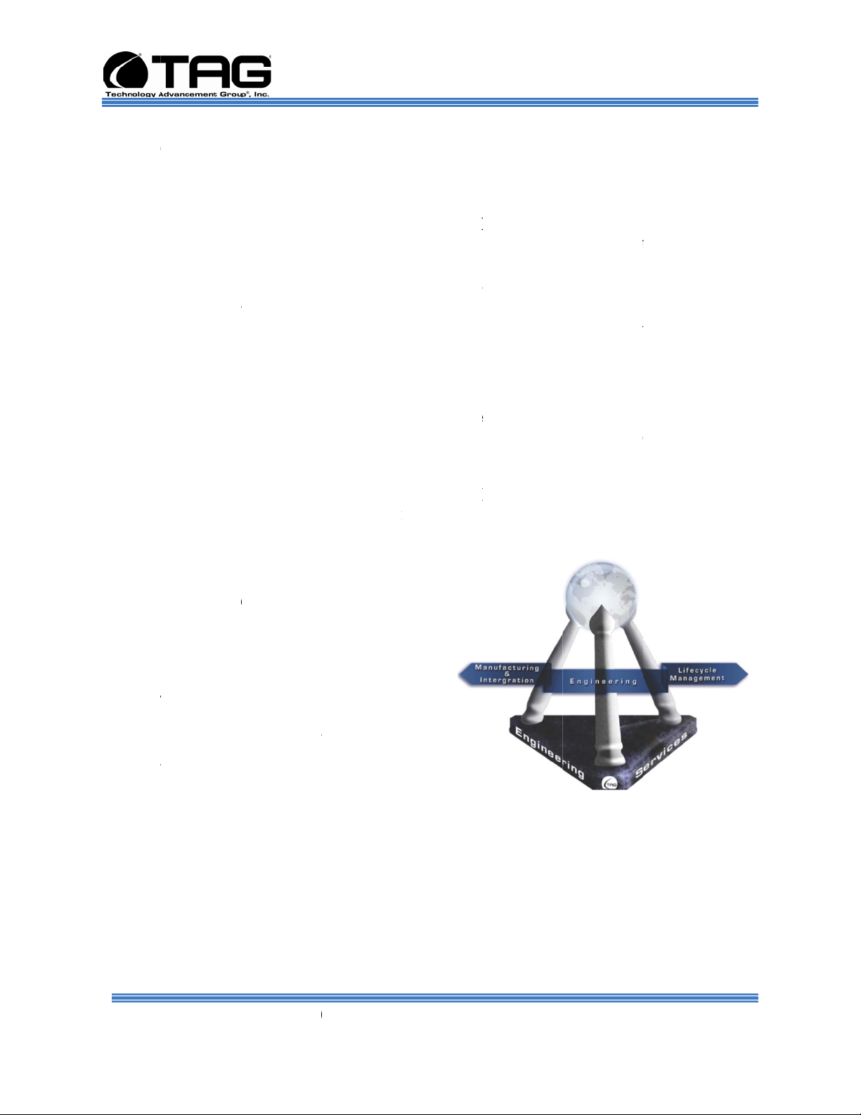
TAG’sMi
challeng
• E
•
TAG ha
these ten
foundati
consiste
ccess lies i
Statement a
ess model t
ons are exc
lifecycles.
sionistores
swithWorld
gineering;
anufacturin
L
ecycleMan
a proven tr
ets to serve
n to ensure
tly rely on
focusing
d leveragi
ensure the
eded throu
olveourcust
Class:
andIntegr
gemen
ck record i
as a trusted
risk is miti
he compan
n the corpo
g the tenets
customer’s
hout length
mers’IT
tion;and
implemen
advisor to o
ated, expec
, our equip
ate
of
y
ing
r Govern
ations are e
ent, and o
ent custom
xceeded, an
r services.
rs. TAG us
the custo
s this
er can
SV-2
Part
Number:
008080
00-X2 Se
ersion
ver (CEN
1.4. 01/12
RIX / JH
2010
V)
age 3 of
2
Page 4
n
2
n
e
i
v
n
o
d
i
t
h
s
1
A
r
m
t
i• A
A
w• Din
p
u
m
g
t
n
1
m
e
s
e
t
e
r
n
t
i
i
m
i
u
L
m
h
r
e
2
o
u
e
y
n
n
n
a
0
e
n
y
u
s
T
p
r
i
e
r
e
t
m
c
u
t
o
a
a
z
p
r
V
o
v
p
p
e
t
k
o
G
a
s
-
r
d
T
E
r
u
r
b
a
n
o
p
p
e
d
T
/
s
u
a
w
g
t
c
r
y
e
u
d
o
G
g
S
p
n
u
e
e
i
u
m
p
m
o
s
P
(
g
o
e
e
a
r
u
E
a
i
e
s
c
’
8
m
l
m
f
Operatio
2.
s Manual
Core C
ompetenc
s
TAG’s e
rigorous
Comput
prototyp
met at e
ensuring
to demo
through
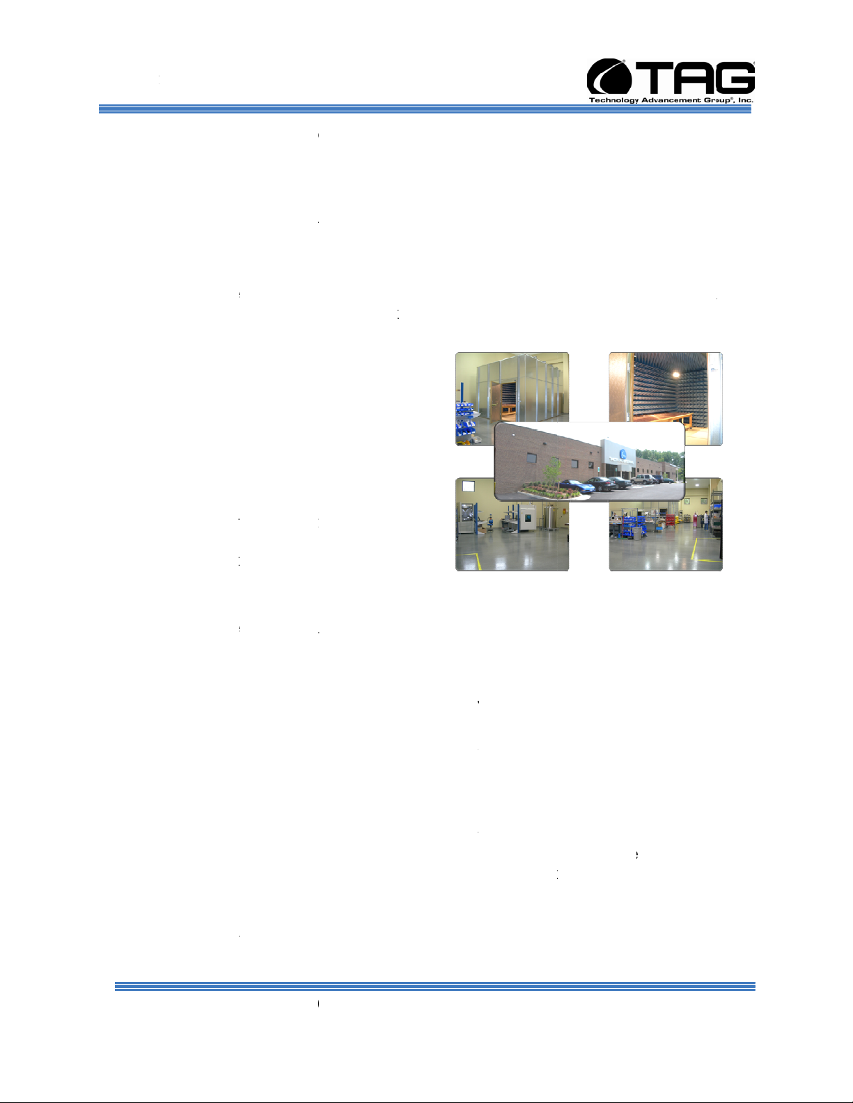
TAG pri
and facil
invested
TAG to
the hars
military
and DO
TAG’s o
Highly
Chambe
test cha
thermal
gineering
design revi
-Aided De
ng process
ery step of
all entranc
strate requi
ut the desig
es itself on
ties. Over
in several p
est and cert
est environ
tandards –
60D.
nsite test eq
ccelerated
, an Electro
ber, and a
est chambe
2.2.1 E
ethodolog
ws. Altho
ign (CAD)
s, and diver
he design.
and exit cri
ement com
process.
its enginee
he past thre
eces of equ
fy products
ental requi
ncluding th
ipment cur
ifecycle T
agnetic In
igh-/low-te
. TAG’s fa
gineering
is built up
gh PMs dri
tools, Com
e test equi
AG Engin
teria are me
liance, ris
ing laborat
e years, TA
pment that
directly on
rements of
MIL-STD
ently inclu
sting (HAL
erference (
perature
ility also p
n Multi-Di
e the sched
utational Fl
ment and f
ering follo
at each sta
s are mitiga
ries
has
llow
ite to
810F
es a
)
MI)
ovides:
ciplinary O
le at TAG,
uid Dynami
cilities to e
s a proven
e. Rigoro
ed, and dec
timization
Engineerin
cs (CFD) m
sure requir
design-revi
s document
isions are p
MDO) and
leverages
dels, rapid
ments are b
w process,
tion is co
udent –
eing
piled
• F
•
TAG im
art prod
TAG’s
Manufac
operatin
manufac
Part
loor plan d
l
nes
dedicated
modern pr
ith external
edicated Q
spection
lements C
ction facilit
anufacturi
turing. Co
in isolatio
uring oper
Number:
signed to s
4-hour syst
duction sta
web collab
ality Assur
2.2.2 M
llular Manu
to minimi
g facility is
sistent with
; however
tions, costs,
SV-2
008080
pport a cell
em burn-in
us tracking
ration capa
nce workst
nufacturi
facturing pr
e waste by
physically
the model,
ersonnel an
and the pro
00-X2 Se
ersion
lar manufa
oom
and Enterp
ilities
tions for s
g and Int
cesses thro
roducts an
artitioned t
ach of TA
d tools are s
uction/inte
ver (CEN
1.4. 01/12
turing mod
ise Resourc
stem compl
gration
gh our co
maximize
model the
’s producti
hared acros
ration sche
RIX / JH
2010
l with mod
Planning (
ance and v
partmental
roduction
ajor philo
n cells are
all cells to
dule. TAG
V)
lar assemb
RP) syste
lidation
zed, state-o
fficiency.
ophies of L
apable of
streamline
s floor
age 4 of
y
-the-
ean
2
Page 5
Operations Manual
technicians are cross-trained in multiple disciplines so they can be redistributed to any cell that
encounters production bottlenecks, which ensures optimal efficiency.
2.2.3 Lifecycle Management
TAG’s world-class Program Management discipline models the renowned methodologies of the
Project Management Institute (PMI) to ensure successful completion of the task at hand. Our
Program Managers (PMs) serve as the voice of the customer – driving requirements to which the
rest of TAG’s organization answers. As an explicit tenet of TAG’s corporate mission statement,
the PMs not only track cost, schedule, and technical compliance throughout a project’s period of
performance, but also ensure the customer is supported well beyond it.
SV-2000-X2 Server (CENTRIX / JHSV)
Part Number: 1008080 Page 5 of 82
Version 1.4. 01/12/2010
Page 6

Operations Manual
2.3 About TAG
2.3.1 Summary of Qualifications.
Providing engineering services and solutions
for our national defense and homeland security
is a responsibility that we don't take lightly.
TAG is a recognized industry leader in
developing defense technologies and
advanced electronics that support some of the
most complex solutions for battlespace
information networks and management
systems in the world.
Our customers depend on our expertise to
translate functional requirements and
performance objectives into specific design
criteria for individual elements and subsystems that comprise larger mission critical
systems. For more than twenty years, we have
dedicated our experience in engineering to the
design of innovative rugged solutions for
military and government, and to providing a
wide range of enterprise services and
Information Assurance in support of the
Defense Information Systems Agency's (DISA)
Net-Centric initiatives.
2.3.2 Core Competencies
TAG designs, manufactures, and supports
advanced communications electronics as well
as integrates, operates, and supports the users
of defense communication and information
networks for several technology programs in
the United States and abroad. TAG has two
operating segments consisting of the Rugged
Systems and Information and Engineering
Services business units;
Rugged Systems provides mechanical,
electrical, and thermal engineering for the
design and development of MIL-STD certified
electronic data enabled systems that are built
SV-2000-X2 Server (CENTRIX / JHSV)
Part Number: 1008080 Page 6 of 82
Version 1.4. 01/12/2010
Page 7

Operations Manual
for in-theater survivability and communication
capability over joint enterprise platforms such
as DSN, GIG, STEP, GBS, and JTRS. This
includes the custom ruggedization of
commercial-off-the-shelf (COTS) and nondevelopmental items (NDI). TAG's mechanical
engineering division designs and fabricates
custom hardened enclosures, using high
performance metal materials, to house and
protect a variety of sensitive devices and
controls. TAG's electrical engineering division
designs programmable power solutions and
advanced sensor technologies including digital
receivers, advanced digital signal processors
and thermal detection systems. TAG's thermal
engineering applies survivability techniques to
ensure systems and instruments are designed
to withstand harsh environmental conditions
encountered by land-based, airborne, and
shipboard system in operations
Information and Engineering Services provides
a wide range of customer support operations,
enterprise network and communications
engineering services combining the experience
and expertise required to achieve network and
communication interoperability for component
hardware and software elements. This includes
design, simulation, analysis, and testing of the
components or systems for the support of
command and control operations. Our team of
national security cleared network engineering
professionals provides planning support for
information systems, architectures, and
networks while developing strategies that lay
the groundwork for sound technical
foundations for programmatic plans. Our
expertise in analyzing, designing,
implementing, and managing network,
telecommunication and security solutions
addresses the full lifecycle approach to
providing mission oriented enterprise class
services
.
SV-2000-X2 Server (CENTRIX / JHSV)
Part Number: 1008080 Page 7 of 82
Version 1.4. 01/12/2010
Page 8
Operations Manual
Document Revision History
Date Version Number Updated By Description of
Changes
01/29/2008 1.0 Alan Huckerby Author
04/10.2008 1.1 Alan Huckerby Author
10/01/09 1.2 Sean Legg Draft Update
10/26/2009 1.3 Alan Huckerby Update
01/12/2010 1.4 Alan Huckerby Update
SV-2000-X2 Server (CENTRIX / JHSV)
Part Number: 1008080 Page 8 of 82
Version 1.4. 01/12/2010
Page 9

Operations Manual
3 About This Manual
3.1 Scope and Audience
3.1.1 Organization:
This manual provides information on the SV-2000-X2
Server. The rugged SV-2000-X2 Server allows for up to 16
cores in a 2U chassis as well as up to 64GB of RAM. The
Server meets military standards such as shock, vibration,
and humidity. TAG built the SV-2000-X2 to relieve potential
problems with a single failing power supply and to create a
product that end users can rely on. Each Server features
two 2.33GHz dual-core INTEL® XEON 5149 processors to
maximize the processing power. The SV-2000-X2 is ideal
for transit case and deployable situations where such high
density computing minimizes size, weight, and power.
This manual is divided into the following chapters and
appendix:
• Chapter 1 provides Cautions and Warnings.
• Chapter 2 provides detailed information on the external and
internal Server components.
• Chapter 3 provides procedures for replacing Hot-Swappable
and LRU components, as well as for replacing or adding
system memory.
• Chapter 4 provides a high-level overview that defines RAID,
the advantages and disadvantages of various RAID levels,
and guidelines to observe when implementing RAID.
SV-2000-X2 Server (CENTRIX / JHSV)
Part Number: 1008080 Page 9 of 82
Version 1.4. 01/12/2010
Page 10

Operations Manual
Table of Contents
Contents
1 Copyright © 2008 Technology Advancement Group®, Inc. (TAG®) ........................................2
1.1 Trademarks ............................................................................................................................2
2 About TAG ..................................................................................................................................3
2.1 Summary of Qualifications ....................................................................................................3
2.2 Core Competences .................................................................................................................4
2.2.1 Engineering ......................................................................................................................4
2.2.2 Manufacturing and Integration ........................................................................................4
2.2.3 Lifecycle Management .....................................................................................................5
2.3 About TAG ............................................................................................................................6
2.3.1 Summary of Qualifications. .............................................................................................6
2.3.2 Core Competencies ..........................................................................................................6
3 About This Manual ......................................................................................................................9
3.1 Scope and Audience ...............................................................................................................9
3.1.1 Organization:....................................................................................................................9
4 Safety Instructions .......................................................................................................................15
4.1 Types of warnings used in this manual ..................................................................................15
4.1.1 Safety Symbols and Labels ..............................................................................................15
4.1.2 Conventions .....................................................................................................................15
5 Server Overview ..........................................................................................................................18
5.1 Product Information ...............................................................................................................18
5.2 SV-2000-X2 Server ...............................................................................................................19
5.2.1 Specifications ...................................................................................................................19
5.2.2 Additional specifications .................................................................................................20
5.2.3 SV-2000-X2 Server Highlights........................................................................................20
5.2.4 SV-2000-X2 Server .........................................................................................................21
5.3 Server Components ................................................................................................................21
5.3.1 Motherboard Model and Type .........................................................................................21
5.4 System Memory .....................................................................................................................22
5.4.1 Identifying System Memory ............................................................................................22
5.5 Identifying your I/O Connectors ............................................................................................22
5.6 Standard Server Components .................................................................................................23
5.6.1 Floppy Drives...................................................................................................................23
5.6.2 SCSI HP 920 LTO-3 Ultrium tape drive .........................................................................23
5.6.3 D/DVD Drive ...................................................................................................................24
5.6.4 Dual-redundant, auto-sensing power supply....................................................................25
5.7 PCI I/O Expansion Cards .......................................................................................................27
5.7.1 Adaptec 5805 SAS/SATA RAID Controller ...................................................................27
5.7.2 Adaptec 29320 ALP-R SCSI Controller ..........................................................................28
6 Procedures ....................................................................................................................................30
6.1 Server Startup.........................................................................................................................30
SV-2000-X2 Server (CENTRIX / JHSV)
Part Number: 1008080 Page 10 of 82
Version 1.4. 01/12/2010
Page 11

Operations Manual
6.2 Server Shutdown ....................................................................................................................30
6.3 Identifying Server Components Using Device Manager .......................................................30
6.4 Working with Device Properties ............................................................................................33
6.5 Installing and Removing Hardware in Windows ...................................................................35
6.5.1 Using the Add New Hardware Wizard ............................................................................35
6.6 Installing Legacy Peripherals .................................................................................................37
6.6.1 Removing Legacy Peripherals .........................................................................................37
6.7 TAG Approved BIOS ............................................................................................................40
6.7.1 Common BIOS Settings ...................................................................................................40
6.8 Bios Configuration for SV-2000-X2 .....................................................................................44
6.9 Upgrading Memory and Replacing Hot-Swap and LRU Components .................................53
6.9.1 Preventing Static Electricity ............................................................................................53
6.10Replacing a Hot-Swap Power Supply Module ......................................................................54
6.11Replacing a Hot-Swap Hard Drive ........................................................................................55
6.11.1 146GB SAS Hard Drive ................................................................................................56
6.12Removing the Server Cover ...................................................................................................56
6.13Adding or Replacing System Memory ..................................................................................56
6.13.1 Install system memory. ..................................................................................................57
6.14Replacing the CMOS Battery ................................................................................................58
6.15Ultrium 920 Tape Drive .........................................................................................................59
6.15.1 Remove Tape Drive .......................................................................................................59
6.15.2 Install Tape Drive ..........................................................................................................59
7 RAID ............................................................................................................................................62
7.1 RAID Defined ........................................................................................................................62
7.1.1 RAID Level 5 ...................................................................................................................63
7.2 Create a RAID 5 Array On Adaptec 5805 .............................................................................64
7.3 About RAID Global and Hot Spares .....................................................................................81
7.4 Global and Dedicated Hot Spares ..........................................................................................81
SV-2000-X2 Server (CENTRIX / JHSV)
Part Number: 1008080 Page 11 of 82
Version 1.4. 01/12/2010
Page 12

Operations Manual
List of Figures
Figure 5-1 SV-2000-X2 (Front View) ...................................................................................... 18
Figure 5-2 SV-2000-X2 Server Components and Connectors (Front View) .................... 21
Figure 5-3 I/O Connectors ........................................................................................................ 23
Figure 5-4 Low Profile Internal Floppy Drive ......................................................................... 23
Figure 5-5.5 Internal Tape Drive .............................................................................................. 24
Figure 5-6 Slot-loading low-profile DVD±R (DL)/-RAM/CD-RW Drive ............................... 24
Figure 5-7 Hot-Swap Power Supply ........................................................................................ 26
Figure 5-8 Adaptec 5805 RAID Card ...................................................................................... 27
Figure 5-9 Adaptec 29320 ALP-R SCSI Controller .............................................................. 28
Figure 6-1 Control Panel ........................................................................................................... 31
Figure 6-2 System Properties................................................................................................... 31
Figure 6-3 Device Manger ........................................................................................................ 32
Figure 6-4 Device Manager ...................................................................................................... 33
Figure 6-5 Properties Dialog Box ............................................................................................ 34
Figure 6-6 Control Panel ........................................................................................................... 36
Figure 6-7 Add hardware Wizard ............................................................................................. 36
Figure 6-8 Control Panel ........................................................................................................... 37
Figure 6-9 System Properties................................................................................................... 38
Figure 6-10 Device Manger ...................................................................................................... 39
Figure 6-11 Quiet Boot .............................................................................................................. 44
Figure 6-12 Load Optimized Defaults ..................................................................................... 45
Figure 6-13 Enhanced Intel ...................................................................................................... 46
Figure 6-14 Enhanced Intel, Disable ....................................................................................... 47
Figure 6-15 Processor Confirmation Screen ......................................................................... 48
Figure 6-16 Deep C-state Support Screen ............................................................................ 49
Figure 6-17 USB Configuration ................................................................................................ 50
Figure 6-18 Intel Virtualization Technology ............................................................................ 51
Figure 6-19 Save and Reset .................................................................................................... 52
Figure 6-20 Grounding Wrist Strap ......................................................................................... 53
Figure 6-21 Hot-Swap of 2U Server Power Supply Module ................................................ 55
Figure 6-22 146GB SAS HDD (Removed from HD Carrier) ............................................... 56
Figure 6-23 DIMM Module Bank .............................................................................................. 58
Figure 7-1 Array Configuration ................................................................................................. 64
Figure 7-2 Initialize Drives ........................................................................................................ 65
Figure 7-3 Select Drives ............................................................................................................ 66
Figure 7-4 Initialization Warning .............................................................................................. 66
Figure 7-5 Initialized .................................................................................................................. 66
Figure 7-6 Create Array............................................................................................................. 67
Figure 7-7 Select Drives ............................................................................................................ 68
Figure 7-8 RAID 5 ...................................................................................................................... 69
Figure 7-9 Array Label ............................................................................................................... 70
Figure 7-10 Array Size .............................................................................................................. 71
SV-2000-X2 Server (CENTRIX / JHSV)
Part Number: 1008080 Page 12 of 82
Version 1.4. 01/12/2010
Page 13

Operations Manual
Figure 7-11 Stripe Size .............................................................................................................. 72
Figure 7-12 Read Caching ........................................................................................................ 73
Figure 7-13 Cache Functionality .............................................................................................. 74
Figure 7-14 Write Caching ........................................................................................................ 75
Figure 7-15 Build/Verify ............................................................................................................. 76
Figure 7-16 Press Enter ............................................................................................................ 77
Figure 7-17 Cache Warning ..................................................................................................... 78
Figure 7-18 Hot Spare Check .................................................................................................. 79
Figure 7-19 Exit Utility ............................................................................................................... 80
SV-2000-X2 Server (CENTRIX / JHSV)
Part Number: 1008080 Page 13 of 82
Version 1.4. 01/12/2010
Page 14

Operations Manual
Chapter 1
Cautions and Warnings.
Electronically distributed. Subject to user discretion when printed.
SV-2000-X2 Server (CENTRIX / JHSV)
Part Number: 1008080 Page 14 of 82
Version 1.4. 01/12/2010
Page 15
Operations Manual
4 Safety Instructions
4.1 Types of warnings used in this manual
Read this manual thoroughly, paying
special attention to the cautions and warnings.
4.1.1 Safety Symbols and Labels
DANGER
WARNING
CAUTION
4.1.2 Conventions
These warnings and cautions indicate
situations or practice that might result in
property damage.
4.1.2.1 Important Messages
4.1.2.2 Warnings
Important messages appear where
mishandling of components is possible or when
work orders can be misunderstood. These
messages also provide vital information
associated with other aspects of system
operation. The word “important” is written as
“IMPORTANT,” both capitalized and bold and
is followed by text in italics. The italicized text
is the important message.
Warnings appear where overlooked details
may cause damage to the equipment or result
in personal injury. Warnings should be taken
seriously. Warnings are easy to recognize. The
word “warning” is written as “WARNING,” both
SV-2000-X2 Server (CENTRIX / JHSV)
Part Number: 1008080 Page 15 of 82
Version 1.4. 01/12/2010
Page 16

Operations Manual
capitalized and bold and is followed by text in
italics. The italicized text is the warning
message.
4.1.2.3 Cautions
Cautionary messages should also be heeded
to help you reduce the chance of losing data or
damaging the system. Cautions are easy to
recognize. The word “caution” is written as
“CAUTION,” both capitalized and bold and is
followed by text in italics. The italicized text is the
cautionary message.
4.1.2.4 Notes
Notes inform the reader of essential but noncritical information. These messages should be
read carefully as any directions or instructions
contained therein can help you avoid making
mistakes. Notes are easy to recognize. The
word “note” is written as “NOTE,”
SV-2000-X2 Server (CENTRIX / JHSV)
Part Number: 1008080 Page 16 of 82
Version 1.4. 01/12/2010
Page 17

Operations Manual
Chapter 2
SV-2000-X2 2U Server.
Electronically distributed. Subject to user discretion when printed.
SV-2000-X2 Server (CENTRIX / JHSV)
Part Number: 1008080 Page 17 of 82
Version 1.4. 01/12/2010
Page 18
Operations Manual
5 Server Overview
5.1 Product Information
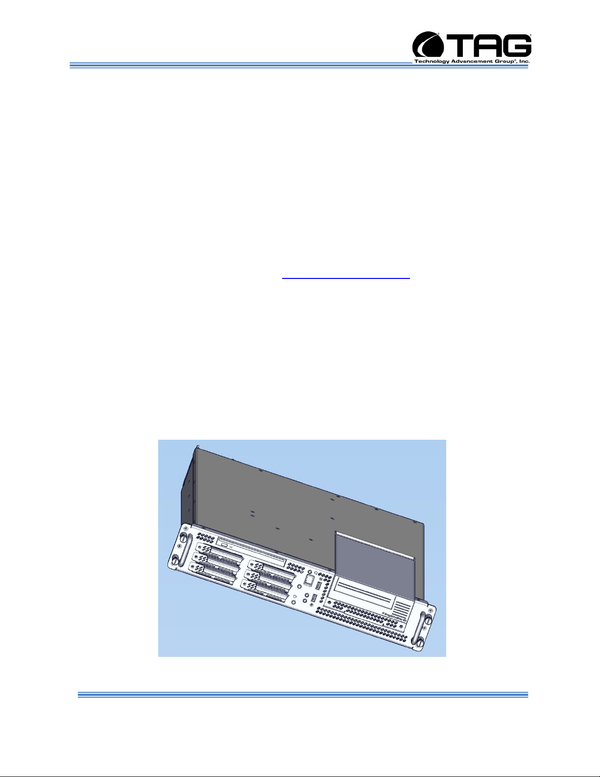
This chapter provides an introductory overview
of the TAG family of rugged Servers. TAG
Servers are highly customizable; the specific
components vary depending on the mission
requirements. Your system may contain
components not described in this chapter. For
detailed information on these components,
refer to the manufactures website or contact
TAG Technical Support at
tech.support@tag.com.
TAG's rugged Servers combine two 2.33GHz
dual-core Intel® Xeon processors with state-ofthe-art mechanical, thermal and electrical
engineering to create customized systems that
perform above and beyond end user or
program specifications. Our rugged Servers
are designed to meet and exceed many MILSTD requirements to ensure survivability in the
field.
Figure 5-1 shows a SV-2000-X2 with off the
shelf standard configuration.
Figure 5-1 SV-2000-X2 (Front View)
SV-2000-X2 Server (CENTRIX / JHSV)
Part Number: 1008080 Page 18 of 82
Version 1.4. 01/12/2010
Page 19

Operations Manual
5.2 SV-2000-X2 Server
All specifications detailed below are for the
standardized version of the SV-2000-X2
5.2.1 Specifications
Chassis & power supply:
• 2U Heavy-duty, 090inch
Aluminum/Magnesium alloy, rack-mount
chassis
• 3.5”H x 19”W x 20”D (approx)
• Redundant, Hot-Swap, auto-sensing power
supplies
• Cooling system developed specifically for
harsh environments
• Front accessible on/off switches
• (2) Front Accessible USB 2.0 Ports
Fan Controller
Processor & Cache:
• Intel 5000P Chipset, 1333MHz FSB
Motherboard and On-board Features:
• On-board graphics controller with 16MB of
RAM.
• (2)USB 2.0 Ports at rear
• (2) 10/100/1000 Ethernet ports
• (2) PCI-Express slots
• (1) PCI-X Expansion slot
• One USB 2.0 Header brought out to front of
chassis
• PS/2 Keyboard & Mouse port
• Expandable to 64GB FB Dimm
System Components:
• 32GB DDR RAM
• (6) 146 GB Hot-Swap, removable SAS Hard
Drives with rugged metal carriers & receivers
• Adaptec 5809 SATA/SAS Raid Controller
• Adaptec 29320ALP-R SCSI Controller
• Removable SCSI HP 920 LTO-3 Ultrium tape
drive
SV-2000-X2 Server (CENTRIX / JHSV)
Part Number: 1008080 Page 19 of 82
Version 1.4. 01/12/2010
Page 20

Operations Manual
• Low-profile DVD±RW(DL),-RAM,CD-RW drive
5.2.2 Additional specifications
• Input voltage range: 115 Vrms nominal, 98 to
138 Vrms (-15%, +20%)
• Input frequency range: 60 Hz nominal, 56.4 to
63.6 Hz (- 6%, + 6%)
• Maximum operating power: 494.4 Watts
• Maximum operating current: 4.12 Amps
• Typical operating power: 410.4 Watts
• Typical operating current: 3.42 Amps
• Idle power: 367 Watts
• Idle current: 3.059 Amps
• AC Input Power connector: IEC 320
• PFC: .97 typical
• Operating temp range: 0-50°C
• Non-operating temp range: -40-70°C
• Operating humidity: up to 90% non-condensing
5.2.3 SV-2000-X2 Server Highlights
• The SV-2000-X2 is unlike any other Server that
is currently on the market. The SV-2000-X2 is
ideal for use in deployable situations where the
product’s compact size, high density
computing, minimized size, weight, and power
make for a highly portable, rugged and reliable
system.
SV-2000-X2 Server (CENTRIX / JHSV)
Part Number: 1008080 Page 20 of 82
Version 1.4. 01/12/2010
Page 21
Operations Manual
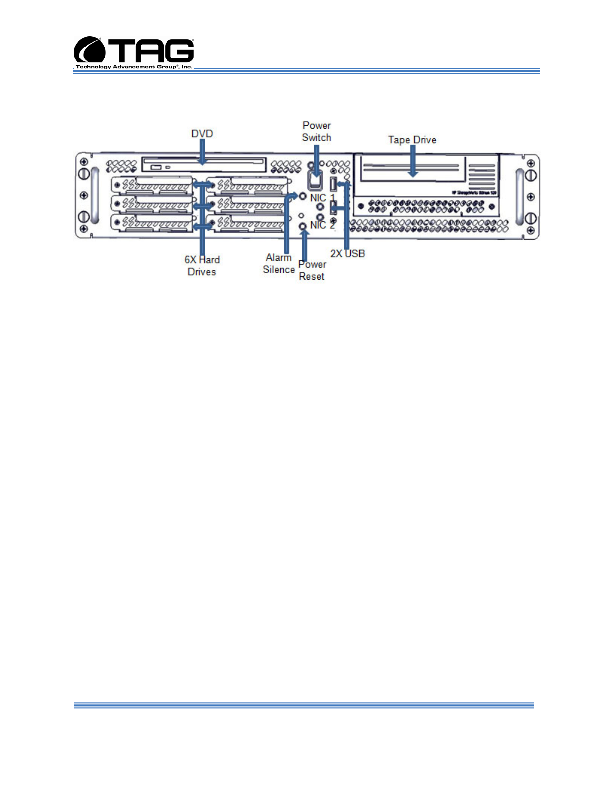
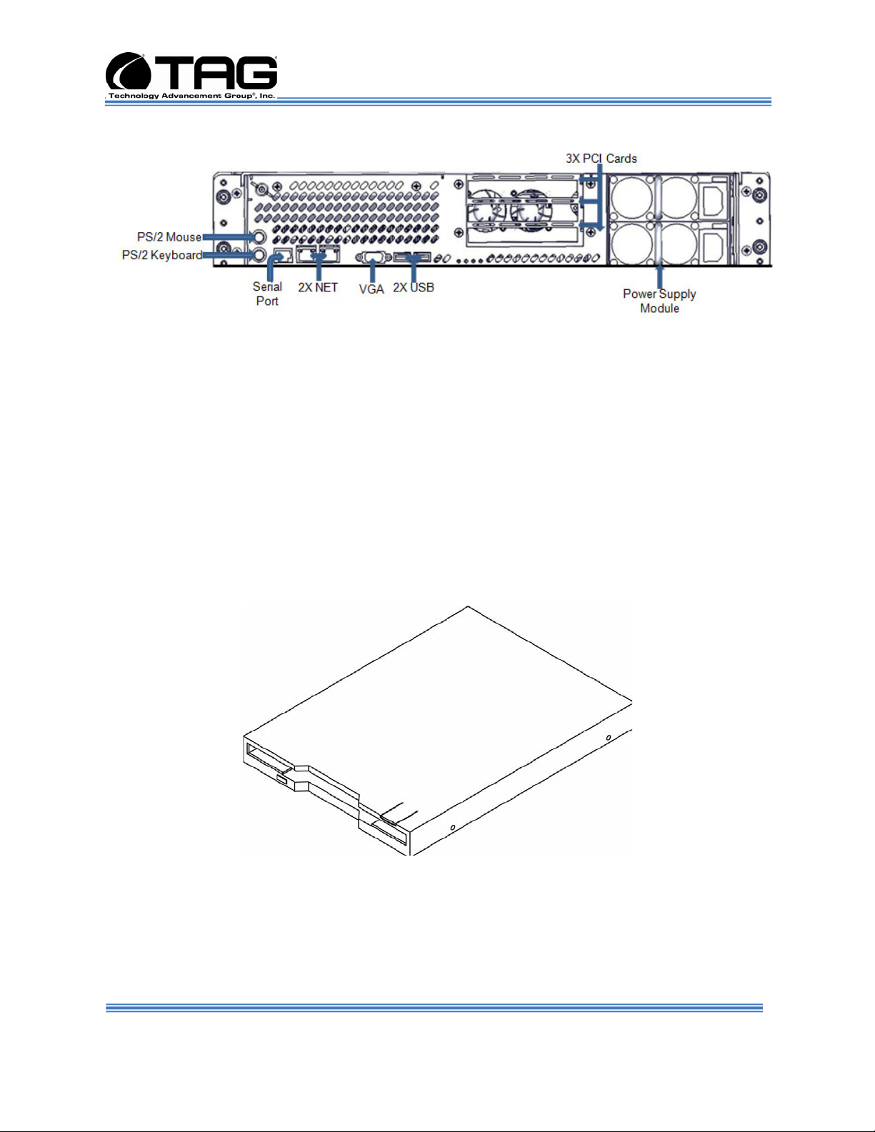
5.2.4 SV-2000-X2 Server
Figure 5-2 SV-2000-X2 Server Components and Connectors (Front View)
5.3 Server Components
This section provides an overview of the most
common components installed in TAG rugged
Servers. Information is also provided on how to
identify specific components within your
Server. For detailed information on the specific
components installed in your Server, refer the
manufactures website.
5.3.1 Motherboard Model and Type
The version of an Intel Server motherboard can
be determined by decoding the last three digits
of the board part number.
For example: For the product C44686-703, the
number following the "-" is as follows:
7 = Fabrication (FAB) Number
03 = Revision 3.
The board part number can be found on the
motherboard. The board part number can also
be determined by using Intel Server
Management software.
SV-2000-X2 Server (CENTRIX / JHSV)
Part Number: 1008080 Page 21 of 82
Version 1.4. 01/12/2010
Page 22

Operations Manual
5.4 System Memory
The type and amount of system memory, or
RAM (random access memory), on your Server
depends on the motherboard installed and how
it was configured.
5.4.1 Identifying System Memory
Refer to your Motherboard Model and Type.
Once you have identified the motherboard,
TAG technical support can assist you in
determining the type and amount of system
memory in your system. See “Contacting
information on TAG on back page of this
manual for information on how to contact
Technical Support.
For information on replacing or upgrading your
system memory, refer to “Adding and
Replacing System Memory on page 62.”
5.4.1.1 Power Management
Modern motherboards provide Advanced
Configuration and Power Management
Interface (ACPI) settings such as wake-up,
power button function and standby/suspend
timers. These functions are configured in the
CMOS Setup.
5.5 Identifying your I/O Connectors
Figure 5-3 shows a typical configuration of I/O
connectors. Your configuration may vary
depending on the motherboard installed in your
Server; however, the color coding should
remain consistent. I/O connectors are colorcoded in compliance with PC 99
recommendations.
SV-2000-X2 Server (CENTRIX / JHSV)
Part Number: 1008080 Page 22 of 82
Version 1.4. 01/12/2010
Page 23
Operations Manual
Figure 5-3 I/O Connectors
5.6 Standard Server Components
The following sections provide information on
the standard system components installed on
TAG Servers
5.6.1 Floppy Drives
The floppy disk drive is a removable storage
component and part of the storage subsystem.
The drive style installed in your system is the
Low Profile Internal Floppy Drive.
Figure 5-4 Low Profile Internal Floppy Drive
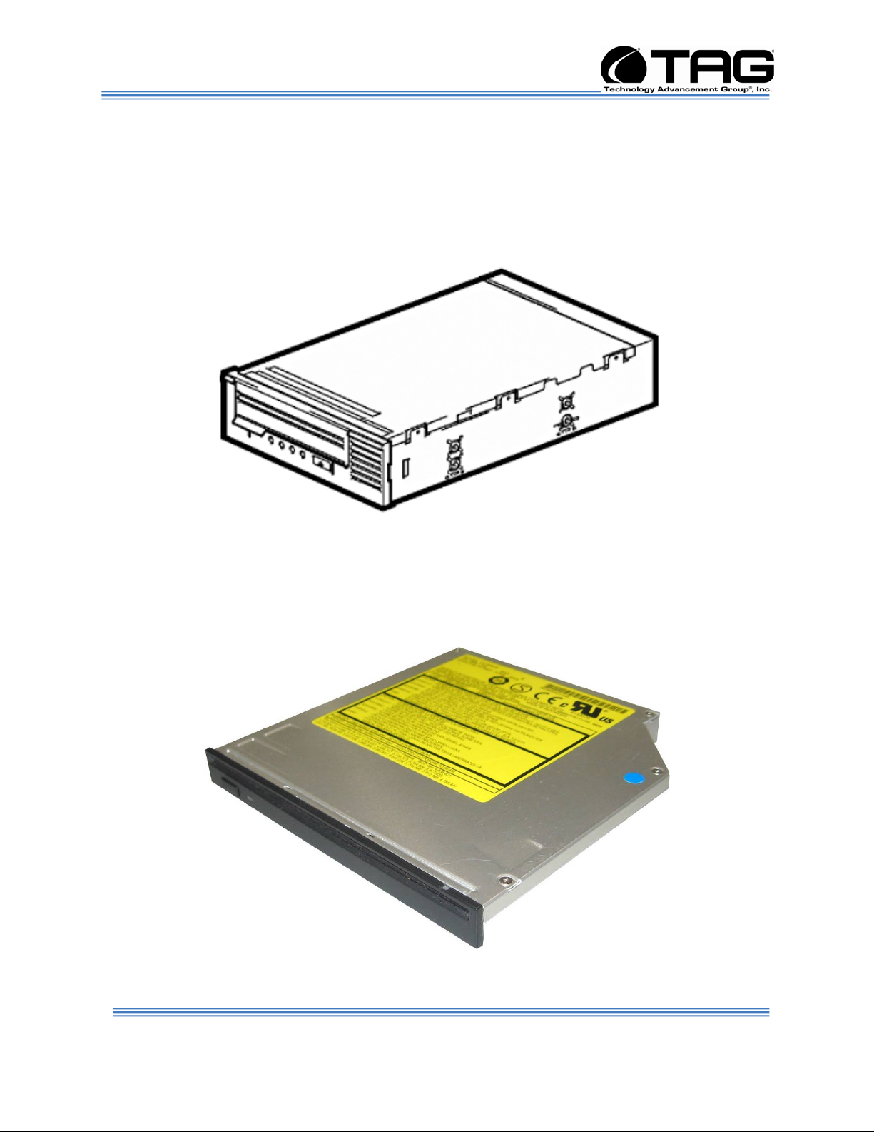
5.6.2 SCSI HP 920 LTO-3 Ultrium tape drive
The Ultrium 3 tape drive technology features a
breakthrough in recording technology by
writing sixteen tracks simultaneously on a
SV-2000-X2 Server (CENTRIX / JHSV)
Part Number: 1008080 Page 23 of 82
Version 1.4. 01/12/2010
Page 24
Operations Manual
linear format of 704 tracks. The data is written
in a serpentine pattern; the tape reverses
direction after each set of eight tracks is
written. This provides higher density recording,
enabling customers to lower costs and
increase efficiency by storing more data on a
single tape in an industry standard format.
Figure 5-5.5 Internal Tape Drive
5.6.3 D/DVD Drive
The type of optical drive installed in your
Server varies per configuration. Figure 5-6.
Figure 5-6 Slot-loading low-profile DVD±R (DL)/-RAM/CD-RW Drive
SV-2000-X2 Server (CENTRIX / JHSV)
Part Number: 1008080 Page 24 of 82
Version 1.4. 01/12/2010
Page 25

Operations Manual
5.6.4 Dual-redundant, auto-sensing power supply
Power for all the equipment in the system is a
dual redundant, Hot-Swap AC input Power
supply with an Input AC Voltage Range
of 115 Vrms nominal, 98 to 138 Vrms (-15%,
+20%).
Input Power Line Frequency
The system shall operate over the input power
frequency range of 60 Hz nominal, 56.4 to 63.6
Hz (- 6%, + 6%).
Power Connector
The AC input power connector is IEC 320
WARNING
Power supplies contain dangerous
voltages. Before attempting to work on any
power supply always unplug the device and
drain the power source by turning the
Server on after the power supply has been
disconnected. Failure to follow these
instructions could result in serious injury
due to electrical shock.
To satisfy reliability requirements, TAG Servers
are designed with Hot-Swappable power
supplies. If in the event of a power supply
module failure or if the power source fails and
only one module is receiving power, an audible
alarm sounds. For procedures on how to HotSwap a power supply module, refer to the
Procedures Section of this manual Replacing a
Hot-Swap Hard Drive55.
Although most TAG power supplies for the 1U
and 4U series Servers are similar in physical
sizes, and physical characteristics, some
Servers use smaller foot print power supplies.
Figure 5-7 shows a typical Hot-Swap power
supply.
SV-2000-X2 Server (CENTRIX / JHSV)
Part Number: 1008080 Page 25 of 82
Version 1.4. 01/12/2010
Page 26

Operations Manual
Figure 5-7 Hot-Swap Power Supply
NOTE: If your Server has two power input
receptacles, then the Server is equipped
with a redundant Hot-Swap power supply.
SV-2000-X2 Server (CENTRIX / JHSV)
Part Number: 1008080 Page 26 of 82
Version 1.4. 01/12/2010
Page 27

Operations Manual
5.7 PCI I/O Expansion Cards
The following sections provide an overview of
the PCI I/O components that may be included
with your Server. For detailed information on
these components, refer to the manufacturers'
websites, or contact TAG Technical Support at
tech.support@tag.com. For more information,
See back page of this document.
5.7.1 Adaptec 5805 SAS/SATA RAID Controller
8 internal port, low profile, PCI-Express (PCIe)
Unified Serial RAID controller with Intelligent
Power Management delivers exceptional
performance, advanced data protection, and
maximum scalability for enterprise-class, highdensity server applications
Figure 5-8 Adaptec 5805 RAID Card
SV-2000-X2 Server (CENTRIX / JHSV)
Part Number: 1008080 Page 27 of 82
Version 1.4. 01/12/2010
Page 28

Operations Manual
5.7.2 Adaptec 29320 ALP-R SCSI Controller
The Adaptec SCSI Card 29320ALP-R is a low
profile, 64-bit 133 MHz PCI-X, single-channel
Ultra320 SCSI card with integrated HostRAID®
RAID 0, 1 and 10 optimized for rack-mount
servers. The Adaptec 29320ALP-R offers
additional drivers for HostRAID and a new
management tool. It provides worry-free data
protection at the fastest SCSI speeds available
up to 320 MByte/sec. The card has a 68-pin
internal connector and a 68-pin VHDCI
external connector for Ultra320 SCSI (LVD)
hard disks drives.
NOTE: Serves as connection to Tape Drive
Figure 5-9 Adaptec 29320 ALP-R SCSI Controller
SV-2000-X2 Server (CENTRIX / JHSV)
Part Number: 1008080 Page 28 of 82
Version 1.4. 01/12/2010
Page 29

Operations Manual
Chapter 3
Procedures
Electronically distributed. Subject to user discretion when printed.
SV-2000-X2 Server (CENTRIX / JHSV)
Part Number: 1008080 Page 29 of 82
Version 1.4. 01/12/2010
Page 30

Operations Manual
6 Procedures
The procedures within this Chapter contain
relevant information to ensure your SV-2000X2 Server maintains its maximum performance
potential.
6.1 Server Startup
1. Check to make sure that all the cables are
seated and connected correctly to the back of
the unit such as keyboard, mouse, monitor
VGA cable and both power cables.
2. Then Press the power switch ON to start the
computer (power switch is located in the front
of the unit)
3. Once the unit starts, System will go thru Power
On self Test (POST) (no action is required at
this time)
4. At windows dialog box press Ctrl, Alt, Delete
at once to login
5. Type in the correct user name and password
and then press enter to login
6. Once the operator is logged on to the unit they
could use the computer as they wish.
NOTE: Assuming the Server is not
connected to any network.
6.2 Server Shutdown
1. The operator needs save any data that is
needed to be saved and then close application
2. Once all data is save and applications are
closed, click on Start menu, select shutdown
and then click OK to shutdown the computer.
6.3 Identifying Server Components Using Device Manager
The Device Manager is one of Windows' most
useful diagnostic tools. It lets you see all of the
devices attached to your computer, and which
resources they are each using. To access the
Device Manager do the following:
SV-2000-X2 Server (CENTRIX / JHSV)
Part Number: 1008080 Page 30 of 82
Version 1.4. 01/12/2010
Page 31

Operations Manual
1. Click Start, point to Settings, and then click
Control Panel. (Figure 6-1).
Figure 6-1 Control Panel
2. Double-click the System icon. (Figure 6-2).
Figure 6-2 System Properties
SV-2000-X2 Server (CENTRIX / JHSV)
Part Number: 1008080 Page 31 of 82
Version 1.4. 01/12/2010
Page 32

Operations Manual
3. Click the Hardware tab, and then click the
Device Manager button. (Figure 6-3).
Figure 6-3 Device Manger
After opening Device Manager, you will see a
list of all the devices Windows detected on
your system. The Device Manager display is
recreated each time the computer is started, or
whenever a dynamic change to the computer
configuration occurs, such as addition of a new
device while the system is running.
NOTE: To include hidden devices, on the
View menu, click Show hidden devices. A
check mark next to Show hidden devices
indicates hidden devices are showing.
Click it again to clear the check mark.
Hidden devices include non-PnP devices
and devices that have been physically
removed from the computer but have not
had their drivers uninstalled.
SV-2000-X2 Server (CENTRIX / JHSV)
Part Number: 1008080 Page 32 of 82
Version 1.4. 01/12/2010
Page 33

Operations Manual
The devices shown represent the computer's
current hardware configuration information.
Any non-functioning devices are displayed with
an exclamation point, indicating that a problem
exists with the device; disabled devices are
displayed with a small red "x" over the icon.
You can use Device Manager to enable or
disable devices, troubleshoot devices, update
drivers, use driver rollback, and change
resources such as interrupt requests (IRQs)
assigned to devices.
6.4 Working with Device Properties
To display a device's properties do the
following:
1. Access the Device Manager as described in
steps 1 through 3 (Figure 6-4).
Figure 6-4 Device Manager
SV-2000-X2 Server (CENTRIX / JHSV)
Part Number: 1008080 Page 33 of 82
Version 1.4. 01/12/2010
Page 34

Operations Manual
2. In the Device manager dialog box (Figure 6-
5).double-click the device, or select the device
and then click the Properties toolbar button
Figure 6-5 Properties Dialog Box
In the device's Properties dialog box, there
might be several tabs. You can view the status
and configuration information, as well as the
device manufacturer, device type, and location
in the upper portion of the General tab.
The Device status box in the middle of the
General tab displays the status of the device,
including any errors. If the device has any
problems, the Device Status box briefly
describes the problem, and usually describes
the appropriate course of action to correct the
problem.
3. Click Troubleshoot... to use the built-in
mechanisms for detecting the nature of the
problem.
Other tabs include the Driver tab, which
displays the details of the driver being used.
This tab also lets you update or uninstall the
SV-2000-X2 Server (CENTRIX / JHSV)
Part Number: 1008080 Page 34 of 82
Version 1.4. 01/12/2010
Page 35

Operations Manual
driver. The Resources tab displays the
hardware resources being used. This tab
allows you to see and resolve any conflicts
caused by non-PnP devices. Along with these
tabs, some devices have additional advanced
settings or tabs for device-specific settings.
6.5 Installing and Removing Hardware in Windows
Plug and Play (PnP) is a standard that makes
installing new hardware devices easier. Prior to
PnP, installing new hardware meant finding
and installing peripheral drivers and making
sure the new device didn't conflict with another
device. Theoretically, if you have a computer
designed for PnP and are using a PnP
operating system (like Windows), installing a
printer, sound card, modem, or other peripheral
is a simple matter of plugging in the device.
It's not always quite this simple. Assuming you
are using a PnP computer, when you attach a
PnP device, you may see a message indicating
that Windows has recognized the new deviceeither immediately or the next time you start up
your system. If Windows needs a driver that is
not currently installed, you may at that point be
asked to insert a disk or the Windows CDROM. If you don't see a message but the
device appears to be working, you can assume
that everything is fine.
6.5.1 Using the Add New Hardware Wizard
If the device is not working properly, try using
the Add New Hardware Wizard. To run this
wizard, do the following:
SV-2000-X2 Server (CENTRIX / JHSV)
Part Number: 1008080 Page 35 of 82
Version 1.4. 01/12/2010
Page 36

Operations Manual
1. From the Start menu, point to Settings and
then click Control Panel. (Figure 6-6).
Figure 6-6 Control Panel
2. Double-click the Add Hardware icon. (Figure
6-7).
Figure 6-7 Add hardware Wizard
SV-2000-X2 Server (CENTRIX / JHSV)
Part Number: 1008080 Page 36 of 82
Version 1.4. 01/12/2010
Page 37

Operations Manual
6.6 Installing Legacy Peripherals
When you install what Microsoft calls a legacy
peripheral, you will need to use the Add
Hardware Wizard, as described “Error!
Reference source not found.” on page
XXXX, to let Windows know about the new
device.
NOTE: The term legacy refers to anything
that's no longer on the cutting edge.
6.6.1 Removing Legacy Peripherals
When removing a legacy peripheral from your
system, you need to let Windows know that the
device is gone. This enables Windows to reuse the
resources (places in memory and internal
communications channels) that it previously
allocated to that device.
To tell Windows that you have removed a legacy
device, perform the following steps:
1. From the Start menu, point to Settings and then
click Control Panel.
(Figure 6-8).
Figure 6-8 Control Panel
SV-2000-X2 Server (CENTRIX / JHSV)
Part Number: 1008080 Page 37 of 82
Version 1.4. 01/12/2010
Page 38

Operations Manual
2. Double-click the System icon. (Figure 6-9).
Figure 6-9 System Properties
3. Click the Hardware tab.
SV-2000-X2 Server (CENTRIX / JHSV)
Part Number: 1008080 Page 38 of 82
Version 1.4. 01/12/2010
Page 39

Operations Manual
4. Click the Device Manager button. (Figure 6-
10).
Figure 6-10 Device Manger
5. Click the name of the item you have removed from
your system. If you don't see the item, look for a
category heading that describes the type of device
you removed, and then click the plus sign to its left
to display a list of items in that category.
6. From the Action menu, click Uninstall.
7. Click OK.
SV-2000-X2 Server (CENTRIX / JHSV)
Part Number: 1008080 Page 39 of 82
Version 1.4. 01/12/2010
Page 40

Operations Manual
6.7 TAG Approved BIOS
The BIOS (basic input/output system) is the
program stored on the CMOS that the Server's
microprocessor uses to get the system started
after you turn it on. The BIOS also manages
data flow between the computer's operating
system and attached devices such as the hard
disk, video adapter, keyboard, and mouse.
CAUTION: The BIOS installed on your
Server was loaded and tested with all the
devices initially installed in your system. If
you desire to have the BIOS updated,
consult TAG technical support in advance
as updates to your approved BIOS may
cause your system to become unstable or
inoperable.
6.7.1 Common BIOS Settings
Printer Parallel Port-Uni., Bi-directional, Disable, Enable, ECP, EPP
6.7.1.1 Printer Parallel Port Uni. Bi-Directional, Disable,
Enable, ECP, EPP.
Settings in the CMOS enable you to configure
a parallel port to use Enhanced Parallel Port
(EPP) or Enhanced Parallel Port (ECP). ECP.
EPP and ECP are bi-directional standards,
operate in 8-bit, and allow data transfer speed
of approximately 2 MB/s. Some of the main
differences are that ECP supports Direct
Memory Access (DMA) and data compression,
which enables higher transfer rates.
It is also possible to completely disable the
parallel port in the BIOS. Most BIOS' allow you
to set the DMA channel, when the port mode is
set to ECP.
6.7.1.2 Com / Serial Port
Most personal computers have two serial ports.
In the BIOS you can assign
SV-2000-X2 Server (CENTRIX / JHSV)
Part Number: 1008080 Page 40 of 82
Version 1.4. 01/12/2010
Page 41

Operations Manual
COM1/COM2/COM3/COM4 to serial port 1 or
2.
Most BIOS' also allow you to set the I/O and
IRQ but this is mostly done automatically.
6.7.1.3 Floppy Drives
The floppy drive(s) can be enabled or disabled in
the BIOS. The BIOS also allows you to choose the
capacity of the media.
• 360 KB 5.25-inch
• 1.2 MB 5.25-inch
• 720 KB 3.5-inch
• 1.44 MB 3.5-inch
• 2.88 MB 3.5-inch
Some BIOS' allow you to swap A: and B: and
disable seeking a floppy disk for a boot sector
during startup.
6.7.1.4 Hard Drives
Most modern BIOS' allow automatic detection
of disk parameters. The settings can be
individually configured for the primary master
and slave device and the secondary master
and slave device. The following are some of
the primary settings that apply to hard drives
as well as CD/DVD-ROM drives, tape backup
drive, etc.
Common disk types are:
• User-defined Cylinders, Heads, Sectors (CHS)
values
• Auto-automatically detects hard disks
parameters at every startup
• 1-46-predefined combinations of CHS values
• CDROM-used for AT Attachment Packet
Interface (ATAPI) CD-ROM drives
• ARMD-used for ATAPI ZIP and LS 120 drives
• DVDROM
SV-2000-X2 Server (CENTRIX / JHSV)
Part Number: 1008080 Page 41 of 82
Version 1.4. 01/12/2010
Page 42

Operations Manual
Size - Determines the capacity of the drive CHS
values:
• Number of Cylinders
• Number of Heads
• Number of Sectors
• LBA (Large Block Addressing)-technology to
overcome the 528 MB limit
6.7.1.5 Boot Sector Virus
A common setting related to hard drives. When
enabled, the BIOS issues a warning
message/beep if an attempt is made to write to
the boot sector or partition table of a hard disk.
6.7.1.6 Memory
Parity adds an extra bit (odd or even) to the 8bit data-string to ensure data integrity in
memory modules. Its successor, ECC,
provides improved data integrity by adding
information about individual bits.
6.7.1.7 Boot Sequence
This setting is used to control the order that the
BIOS uses during the boot process to look for
a boot device from which to load the operating
system. For example:
• CD
• Floppy
• Hard Disk
6.7.1.8 Date and Time
The Date and Time is set in the BIOS, stored in
CMOS, and maintained by CMOS battery.
6.7.1.9 Passwords
In most cases a user (startup) password and a
supervisor (setup) password can be set in the
CMOS. When a Setup password is required,
SV-2000-X2 Server (CENTRIX / JHSV)
Part Number: 1008080 Page 42 of 82
Version 1.4. 01/12/2010
Page 43

Operations Manual
the computer will prompt for it when you try to
access the BIOS setup. When a Startup
password is configured, the computer will
prompt for it at every startup.
The CMOS password can be reset by
shortening the "CMOS restore to factory
defaults jumper" or by temporarily removing the
CMOS battery.
6.7.1.10 Plug and Play BIOS
Today's BIOS' are Plug_and_play (PnP)aware. This means they are able to
automatically assign resources such as IRQ
and DMA to PnP devices.
Information about PnP devices is stored in a
separate area of non-volatile CMOS memory,
called the Extended System Configuration
Database (ESCD). Both the PnP BIOS and the
operating system can access this area and
communicate with each other about resource
settings assigned to PnP devices as well as
non-PnP devices. For example, when a fixed
interrupt request (IRQ) is manually assigned to
a particular device using Device Manager,
Windows will write this information to the
ESCD on shutdown thereby preventing the
BIOS from assigning the same IRQ to a PnP
device at startup.
You can also reserve IRQs for non-PnP
devices in the CMOS setup, this will prevent
the BIOS from assigning these reserved
resources to PnP devices, a common example
is a legacy sound card that needs IRQ 5
SV-2000-X2 Server (CENTRIX / JHSV)
Part Number: 1008080 Page 43 of 82
Version 1.4. 01/12/2010
.
Page 44

Operations Manual
6.8 Bios Configuration for SV-2000-X2
1. Press F2 to access the Main BIOS Page. On
the Main Page, Select Quiet Boot then select
Enable and press Enter. (Figure 6-11).
Figure 6-11 Quiet Boot
SV-2000-X2 Server (CENTRIX / JHSV)
Part Number: 1008080 Page 44 of 82
Version 1.4. 01/12/2010
Page 45

Operations Manual
2. Back at the Main Screen press F9. On the
drop down menu select and press YES.
(Figure 6-12).
Figure 6-12 Load Optimized Defaults
SV-2000-X2 Server (CENTRIX / JHSV)
Part Number: 1008080 Page 45 of 82
Version 1.4. 01/12/2010
Page 46

Operations Manual
3. In the Advanced Menu scroll down and select
Enhanced Intel press Enter. (Figure 6-13).
Figure 6-13 Enhanced Intel
SV-2000-X2 Server (CENTRIX / JHSV)
Part Number: 1008080 Page 46 of 82
Version 1.4. 01/12/2010
Page 47

Operations Manual
4. In the Enhanced Intel drop down menu select
Disable and press Enter.. (Figure 6-14).
Figure 6-14 Enhanced Intel, Disable
SV-2000-X2 Server (CENTRIX / JHSV)
Part Number: 1008080 Page 47 of 82
Version 1.4. 01/12/2010
Page 48

Operations Manual
5. In Processor Confirmation screen select
Deep C-state Support and press Enter.
(Figure 6-15).
Figure 6-15 Processor Confirmation Screen
SV-2000-X2 Server (CENTRIX / JHSV)
Part Number: 1008080 Page 48 of 82
Version 1.4. 01/12/2010
Page 49

Operations Manual
6. In Deep C-state Support screen select
Disable and press Enter. (Figure 6-16).
Figure 6-16 Deep C-state Support Screen
SV-2000-X2 Server (CENTRIX / JHSV)
Part Number: 1008080 Page 49 of 82
Version 1.4. 01/12/2010
Page 50

Operations Manual
7. In Processor Confirmation screen select
Intel Virtualization Technology and press
Enter. (Figure 6-17).
Figure 6-17 USB Configuration
SV-2000-X2 Server (CENTRIX / JHSV)
Part Number: 1008080 Page 50 of 82
Version 1.4. 01/12/2010
Page 51

Operations Manual
8. In Intel Virtualization Technology drop down
menu select Enabled and press Enter. (Figure
6-18).
Figure 6-18 Intel Virtualization Technology
SV-2000-X2 Server (CENTRIX / JHSV)
Part Number: 1008080 Page 51 of 82
Version 1.4. 01/12/2010
Page 52

Operations Manual
9. In Processor Confirmation screen drop down
menu Save and Reset select Yes and press
F10. (Figure 6-19)
Figure 6-19 Save and Reset
SV-2000-X2 Server (CENTRIX / JHSV)
Part Number: 1008080 Page 52 of 82
Version 1.4. 01/12/2010
Page 53

Operations Manual
6.9 Upgrading Memory and Replacing Hot-Swap and LRU Components
6.9.1 Preventing Static Electricity
This section provides procedures for replacing all
Hot-Swappable and LRU components, including
procedures for replacing or adding system memory.
The components inside your computer are
extremely sensitive to static electricity, also known
as electrostatic discharge (ESD). ESD can
permanently damage electrostatic dischargesensitive components in your Server.
To prevent ESD damage, follow these guidelines
before opening the Server case:
1. Turn off the Server and unplug the power cord
before opening the case.
2. Wear a grounding wrist strap and attach it to a
bare metal part of the Server, workbench, or other
grounded connection.
Figure 6-20 Grounding Wrist Strap
3. Do not insert any object into the vent holes on the
case or the power supply. Touch a bare metal
surface on the back of the computer, a bare metal
surface on your workbench, or other grounded
object before handing DIMMs or other components.
Before working with computer components,
follow these guidelines:
• Avoid static-causing surfaces such as carpeted
floors, plastic, and packing foam.
SV-2000-X2 Server (CENTRIX / JHSV)
Part Number: 1008080 Page 53 of 82
Version 1.4. 01/12/2010
Page 54

Operations Manual
• Remove components from their antistatic bags
only when you are ready to use them. Do not
lay components on the outside of antistatic
bags because only the inside of the bags
provide electrostatic protection. Always hold
memory modules and components by their
edges or their metal mounting brackets.
• Avoid touching the edge connectors and
components on the cards. Never slide memory
modules or components over any surface.
6.10 Replacing a Hot-Swap Power Supply Module
Your TAG Server was designed with the ability
to Hot-Swap a power supply module without
disconnecting system power. Refer to Figure 412 and the steps that follow to Hot-Swap a
power supply module.
NOTE: If you need to remove both
modules, you must shutdown the system,
unplug the power source from the unit and
drain the systems onboard battery by
pressing the on/off switch and holding it in
place for approximately 10 seconds to drain
any charge that might be retained by the
systems motherboard.
1. Obtain certified replacement module from TAG.
For more information on contact information
see document back page.
2. Depending on the series of your Server, either
a retention bracket or filtering cover that is
secured with thumb screws will need to be
removed first.
NOTE: In some cases a screw driver
(Philips head) might be required to remove
a retention bar that is screwed into the
power supply.
3. Loosen the thumb screws on the desired
module to be replaced.
4. Depress the module safety latch and gently pull
the handle as shown in Figure 5-42
SV-2000-X2 Server (CENTRIX / JHSV)
Part Number: 1008080 Page 54 of 82
Version 1.4. 01/12/2010
Page 55

Operations Manual
Figure 6-21 Hot-Swap of 2U Server Power Supply Module
5. Slide the replacement module into the power
supply.
6. Press firmly and evenly on the power module
until you feel the module seat in the back of the
power supply
6.11 Replacing a Hot-Swap Hard Drive
The system's hard drive Hot-Swap feature
enables you to remove a hard drive without
shutting down the operating system or turning
off the system power. The way in which you
remove a hard drive depends on the
application you are using and whether you are
replacing a drive, adding a new one, or
removing a drive permanently.
When you remove a drive using the Hot-Swap
operation, you need to stop the hard drive and
take it offline to remove the logical software
links to the hard drive, and to reconfigure the
file system so that it will now ignore the
removed drive. You might also have to
reconfigure your application software to
operate without the removed drive. Therefore it
is strongly recommended that you contact TAG
Technical Support at tech.support@tag.com
before attempting to Hot-Swap a hard drive.
For more information on contact information
see document back page.
SV-2000-X2 Server (CENTRIX / JHSV)
Part Number: 1008080 Page 55 of 82
Version 1.4. 01/12/2010
Page 56

Operations Manual
6.11.1 146GB SAS Hard Drive
Figure 6-22 146GB SAS HDD (Removed from HD Carrier)
6.12 Removing the Server Cover
CAUTION
The location of the mounting screws securing
the Server cover varies per Server model. To
remove the cover, use a Phillips screwdriver to
remove all screws from the sides and top of the
cover.
NOTE: It is important to make note of the
location from which screws are removed
since different screw lengths may be used
to secure the cover.
It is not safe to operate TAG Servers
without the cover in place. Failure to take
this precaution may result in personal
injury and system damage.
6.13 Adding or Replacing System Memory
This section lists the procedures for adding or
replacing system memory.
SV-2000-X2 Server (CENTRIX / JHSV)
Part Number: 1008080 Page 56 of 82
Version 1.4. 01/12/2010
Page 57

Operations Manual
WARNING
Ensure that the system is powered-down
and all power sources have been
disconnected from the Server prior to
removing or replacing system memory.
Failure to do so could result in serious
injury from electrical shock.
CAUTION
Printed circuit boards and hard drives
contain electronic components that are
extremely sensitive to static electricity.
Ordinary amounts of static from your
clothes or the work environment can
destroy components. Do not touch the
components or any metal parts without taking
proper antistatic precautions.
AG's rugged Servers combine Intel® Xeon®
technology with state-of-the-art mechanical,
thermal and electrical engineering to create
customized systems that perform above and
beyond end user or program specifications.
Our rugged Servers are designed to meet and
exceed many MIL-STD requirements to ensure
survivability in the field.
6.13.1 Install system memory.
Unlatch both DIMM socket
levers, as shown in Figure 4-14.
SV-2000-X2 Server (CENTRIX / JHSV)
Part Number: 1008080 Page 57 of 82
Version 1.4. 01/12/2010
Page 58

Operations Manual
Figure 6-23 DIMM Module Bank
1. Note the location of the alignment notch.
2. Align the notches on the new module with the
notches on the memory and press it firmly into
the bank.
NOTE: The tabs on the sides of the memory
module should secure the DIMM
automatically. When the DIMM locks into
place, you will hear a click.
6.14 Replacing the CMOS Battery
This section lists the procedures for replacing
the motherboard CMOS Battery.
1. Boot up the Server and enter set-up mode.
2. Record all the settings from the various BIOS
menus.
3. Power off the Server.
4. Remove the lid from the Server.
5. Locate the CMOS battery on the motherboard
(ref. Figure , Notation “H”).
6. Remove the old battery.
7. Replace it with the new battery.
8. Replace the lid and power on the Server.
9. Enter the set-up mode of the Server.
10. Re-enter any applicable settings through the
various BIOS menus.
SV-2000-X2 Server (CENTRIX / JHSV)
Part Number: 1008080 Page 58 of 82
Version 1.4. 01/12/2010
Page 59

Operations Manual
6.15 Ultrium 920 Tape Drive
The Ultrium 920 delivers a compressed storage
capacity of 800GB per data cartridge and a
compressed data transfer rate of 432GB per hour.
The Ultrium 920 Tape Drive is fully read and write.
6.15.1 Remove Tape Drive
1. Turn off all power to the server and remove
power cables from their power source.
2. Unscrew the four (4) thumb screws holding the
Tape Drive into place.
3. Pull the Tape Drive body slightly toward the
front of the server and then tilt upward.
Note: Pulling slightly forward will take it from
under the Server top cover.
4. When Tape drive body is in the upright position
remove all cable connections. Then remove
Tape Drive.
5. Pull the top cover off the tape drive body.
6. Remove the four (4) retaining screws that are
holding the bottom cover on to the Tape Drive.
6.15.2 Install Tape Drive
7. Install the bottom cover and its four (4)
retaining screws.
8. Replace the Tape Drive top cover.
SV-2000-X2 Server (CENTRIX / JHSV)
Part Number: 1008080 Page 59 of 82
Version 1.4. 01/12/2010
Page 60

Operations Manual
9. Slide the cover end of the new Tape Drive
under the servers top cover and tighten all four
94) thumb screws.
10. Restore all power cables to their power source.
.Power up the server and test the new Tape
Drive.
SV-2000-X2 Server (CENTRIX / JHSV)
Part Number: 1008080 Page 60 of 82
Version 1.4. 01/12/2010
Page 61

Operations Manual
Chapter 4
RAID.
Electronically distributed. Subject to user discretion when printed.
SV-2000-X2 Server (CENTRIX / JHSV)
Part Number: 1008080 Page 61 of 82
Version 1.4. 01/12/2010
Page 62

Operations Manual
7 RAID
RAID is an acronym for Redundant Array of
Inexpensive (or Independent) Disks. This
section provides a high-level overview that
defines RAID, the advantages and
disadvantages of various RAID levels, and
guidelines to observe when implementing
RAID.
7.1 RAID Defined
RAID is a way of storing data on two or more
physical disks for the purpose of redundancy,
improved performance, or both. The combined
physical disks make up what is called an array.
This array appears on the host system as one
disk. For example, if you have physical disk 1
and physical disk 2, those two disks appear to
the host system as one disk.
RAID consists of different levels, which
determine how the data is placed in the array.
Each RAID level has specific data protection
and system performance characteristics. The
following are commonly used SCSI RAID
levels:
1. RAID Level 0: Striping, good performance, no
redundancy
2. RAID Level 1: Mirroring, one-to-one
redundancy
3. RAID Level 5: Striping with parity striped
across all drives; offers performance and
redundancy
4. RAID Level 10: Mirroring and striping; best
redundancy and best performance
5. RAID Level 50: Parity striped across all drives
in a mirrored set; redundancy and performance
You can manage RAID arrays with a RAID
controller (hardware RAID) or with software
alone (software RAID).
SV-2000-X2 Server (CENTRIX / JHSV)
Part Number: 1008080 Page 62 of 82
Version 1.4. 01/12/2010
Page 63

Operations Manual
7.1.1 RAID Level 5
RAID Level 5 maps the data across the drives
and stores parity information for each data
stripe on different drives in the array. The parity
data, labeled P in Figure , is distributed. This
lessens the data congestion that occurs if all of
the parity data is written to one drive. A RAID 5
array can preserve data if one drive fails.
However, if two drives fail, all data in the array
is lost.
SV-2000-X2 Server (CENTRIX / JHSV)
Part Number: 1008080 Page 63 of 82
Version 1.4. 01/12/2010
Page 64

Operations Manual
7.2 Create a RAID 5 Array On Adaptec 5805
1. Power up your computer. When prompted,
press Ctrl A to enter the ARC Utility.
NOTE: During boot up, if your system has
insufficient memory the following message
will display. “Adaptec RAID Configuration
Utility will load after, system initialization.
Please wait. Or press <Enter> Key to
attempt loading the utility forcibly
[Generally, not recommended]”
2. Select Array Configuration Utility from the
menu and press Enter. (Figure 7-1).
Figure 7-1 Array Configuration
SV-2000-X2 Server (CENTRIX / JHSV)
Part Number: 1008080 Page 64 of 82
Version 1.4. 01/12/2010
Page 65

Operations Manual
3. Select Initialize Drives, and then press
Enter. (Figure 7-2).
Figure 7-2 Initialize Drives
4. Select Initialize all Hard Drives for the
array, press Insert for each selected disk
drive, then press Enter. (Figure 7-3).
SV-2000-X2 Server (CENTRIX / JHSV)
Part Number: 1008080 Page 65 of 82
Version 1.4. 01/12/2010
Page 66

Operations Manual
Figure 7-3 Select Drives
5. During initialization, all data is deleted from
the disk. Before continuing back up any data
you want to keep. (Figure 7-4).
Figure 7-4 Initialization Warning
6. Press YES to continue. (Figure 7-5).
Figure 7-5 Initialized
7. Press any key to continue
SV-2000-X2 Server (CENTRIX / JHSV)
Part Number: 1008080 Page 66 of 82
Version 1.4. 01/12/2010
Page 67

Operations Manual
8. On the ACU screen select Create Array
from the Main Menu and press Enter.
(Figure 7-6).
Figure 7-6 Create Array
SV-2000-X2 Server (CENTRIX / JHSV)
Part Number: 1008080 Page 67 of 82
Version 1.4. 01/12/2010
Page 68

Operations Manual
9. Select the first Five (5) Hard Drives that
were just initialized, press Insert for each
selected disk drive, then press Enter.
(Figure 7-7).
Figure 7-7 Select Drives
SV-2000-X2 Server (CENTRIX / JHSV)
Part Number: 1008080 Page 68 of 82
Version 1.4. 01/12/2010
Page 69

Operations Manual
10. In Array Type select RAID 5 press Enter.
(Figure 7-8).
Figure 7-8 RAID 5
SV-2000-X2 Server (CENTRIX / JHSV)
Part Number: 1008080 Page 69 of 82
Version 1.4. 01/12/2010
Page 70

Operations Manual
11. In Array Label type a name and press
Enter. (Figure 7-9).
Figure 7-9 Array Label
SV-2000-X2 Server (CENTRIX / JHSV)
Part Number: 1008080 Page 70 of 82
Version 1.4. 01/12/2010
Page 71

Operations Manual
12. Array Size Press Enter, then press Enter
again to use the default granularity of GB.
(Figure 7-10).
Figure 7-10 Array Size
SV-2000-X2 Server (CENTRIX / JHSV)
Part Number: 1008080 Page 71 of 82
Version 1.4. 01/12/2010
Page 72

Operations Manual
13. In Stripe Size scroll down and select (25
KB). (Figure 7.11).
Figure 7-11 Stripe Size
SV-2000-X2 Server (CENTRIX / JHSV)
Part Number: 1008080 Page 72 of 82
Version 1.4. 01/12/2010
Page 73

Operations Manual
14. In Read Caching scroll down and select
Enable Max ID. (Figure 7-12).
Figure 7-12 Read Caching
SV-2000-X2 Server (CENTRIX / JHSV)
Part Number: 1008080 Page 73 of 82
Version 1.4. 01/12/2010
Page 74

Operations Manual
15. In Cache Warning press Enter. (Figure 7-
13).
Figure 7-13 Cache Functionality
SV-2000-X2 Server (CENTRIX / JHSV)
Part Number: 1008080 Page 74 of 82
Version 1.4. 01/12/2010
Page 75

Operations Manual
16. In Write Caching select Disable and press
Enter. (Figure 7-14).
Figure 7-14 Write Caching
SV-2000-X2 Server (CENTRIX / JHSV)
Part Number: 1008080 Page 75 of 82
Version 1.4. 01/12/2010
Page 76

Operations Manual
17. In Create RAID select (Build/Verify) and
press Enter. (Figure 7-15).
Figure 7-15 Build/Verify
SV-2000-X2 Server (CENTRIX / JHSV)
Part Number: 1008080 Page 76 of 82
Version 1.4. 01/12/2010
Page 77

Operations Manual
18. Press Enter to continue. (Figure 7-16).
Figure 7-16 Press Enter
SV-2000-X2 Server (CENTRIX / JHSV)
Part Number: 1008080 Page 77 of 82
Version 1.4. 01/12/2010
Page 78

Operations Manual
19. When a cache warning message displays,
type Y. (Figure 7-18).
Figure 7-17 Cache Warning
SV-2000-X2 Server (CENTRIX / JHSV)
Part Number: 1008080 Page 78 of 82
Version 1.4. 01/12/2010
Page 79

Operations Manual
20. Check that a Global Hotspare is available.
(Figure 7.18).
NOTE: Ensure you have previously only
selected five (5) of the available six (6)
drives this will ensure you have a Hot
Spare.
21. After viewing the response press any key to
return to the ACU Menu.
Figure 7-18 Hot Spare Check
SV-2000-X2 Server (CENTRIX / JHSV)
Part Number: 1008080 Page 79 of 82
Version 1.4. 01/12/2010
Page 80

Operations Manual
22. Press Escape. The Exit utility window will
appear. Select YES and press Enter.
(Figure 7-19).
Figure 7-19 Exit Utility
23. Your Computer Restarts
SV-2000-X2 Server (CENTRIX / JHSV)
Part Number: 1008080 Page 80 of 82
Version 1.4. 01/12/2010
Page 81

Operations Manual
7.3 About RAID Global and Hot Spares
A hot spare is a drive that is on standby in case
another drive fails. Depending on how the
array is configured, the drive is either picked up
automatically and the array is rebuilt, or you
manually select the drive (or insert a new drive
in the same slot as the failed drive) and rebuild
the array.
How the hot spare works depends on how the
array is configured. When a drive fails, the
array rebuilds automatically using the hot
spare. This is assuming that automatic rebuild
is enabled. If automatic rebuild is disabled, you
must manually start the rebuild process.
During a rebuild you may notice degraded
performance on the drives.
7.4 Global and Dedicated Hot Spares
A dedicated hot spare is assigned to one or
more arrays, whereas a global hot spare can
be used for any array that is on the same
controller as the hot spare. Also, dedicated hot
spares that reside in the same storage
enclosure typically have better performance
than
global hot spares.
SV-2000-X2 Server (CENTRIX / JHSV)
Part Number: 1008080 Page 81 of 82
Version 1.4. 01/12/2010
Page 82

CONTACT
7.4.1
22355 TAG Way
Dulles, VA 20166
Tel: 1-800-824-8693
www.tag.com
Technical Support
USA 1-800-TAG-TECH
Outside USA
While every precaution has been taken
to ensure the accuracy and completeness
of this literature. TAG assumes
no responsibility and disclaims and liability
for damage resulting from use of this information
or for any errors or omissions.
 Loading...