

Page 1

TAG
22355 TAG Way
Dulles, VA 20166
SV-2000-IX Server
Operations Manual
275-MNL-002
Page 2

Operations Manual
1 Copyright © 2009 Technology Advancement Group (TAG)
All rights reserved. This publication and its contents are proprietary to TAG. No part of
this publication may be reproduced in any form or by any means without the written
permission of TAG, 22355 TAG Way, Dulles, Virginia 20166-9310.
TAG has made every effort to ensure the correctness and completeness of the material
in this document. TAG shall not be liable for errors contained herein. The information in
this document is subject to change without notice. TAG makes no warranty of any kind
with regard to this material, including, but not limited to, the implied warranties of
merchantability and fitness for a particular purpose.
1.1 Trademarks
All trademarks, marks, names, or product names referenced in this publication are the
property of respective owners, and TAG neither endorses nor otherwise sponsors any
such products or services referred to herein.
Document Number: 275-MNL-002 Page 2 of 84
Version 1.0. 08/25/2010
SV-2000-IX
Page 3

Operations Manual
2 About TAG
2.1 Summary of Qualifications
TAG has served as a leading provider of IT solutions to DoD customers over the past 20+ years
and has a long-standing and respected history of providing Systems Engineering, Electronic
Equipment and Program Management support to US Military warfighters. Headquartered in
Dulles, Virginia, TAG’s state-of-the-art 35,000 sq. ft. engineering and manufacturing facility
provides all the infrastructure, equipment, and manpower necessary to engineer, design, test,
manufacture, and certify products to the rugged requirements of the tactical combat theater. Our
facilities in Dulles, VA, San Diego, CA, and St. Louis, MO, allow for rapid deployment of
products and support across the globe.
TAG quickly, efficiently, and cost-effectively tailors rugged solutions for large DoD programs
with specific MIL-STD requirements. TAG’s comprehensive Quality Assurance (QA) policy –
enforced through application of our UL-registered ISO 9001:2000 certified processes – enables
TAG to rapidly deploy systems and solutions that reliably withstand the stresses of the tactical
environment. Today, there are over 20,000 TAG systems deployed across various weapons
platforms throughout the US Military. TAG effectively balances all corporate assets – our
people, expertise, infrastructure, and experience – to consistently and successfully execute and
deliver to the DoD.
TAG’s success lies in focusing on the corporate
Mission Statement and leveraging the tenets of
our business model to ensure the customer’s
expectations are exceeded throughout lengthy
program lifecycles.
TAG’s Mission is to resolve our customers’ IT
challenges with World-Class:
Engineering;
Manufacturing and Integration; and
Lifecycle Management
TAG has a proven track record in implementing
these tenets to serve as a trusted advisor to our Government customers. TAG uses this
foundation to ensure risk is mitigated, expectations are exceeded, and the customer can
consistently rely on the company, our equipment, and our services.
SV-2000-IX
Document Number: 275-MNL-002 Page 3 of 84
Version 1.0. 08/25/2010
Page 4
Operations Manual
2.2 Core Competences
2.2.1 Engineering
TAG’s engineering methodology is built upon Multi-Disciplinary Optimization (MDO) and
rigorous design reviews. Although PMs drive the schedule at TAG, Engineering leverages
Computer-Aided Design (CAD) tools, Computational Fluid Dynamics (CFD) modeling, rapid
prototyping processes, and diverse test equipment and facilities to ensure requirements are being
met at every step of the design. TAG Engineering follows a proven design-review process,
ensuring all entrance and exit criteria are met at each stage. Rigorous documentation is compiled
to demonstrate requirement compliance, risks are mitigated, and decisions are prudent –
throughout the design process.
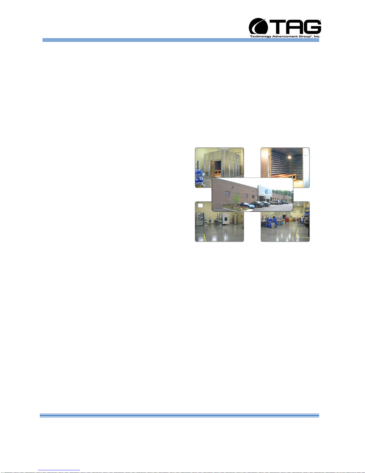
TAG prides itself on its engineering laboratories
and facilities. Over the past three years, TAG has
invested in several pieces of equipment that allow
TAG to test and certify products directly onsite to
the harshest environmental requirements of
military standards – including the MIL-STD-810F
and DO 160D.
TAG’s onsite test equipment currently includes a
Highly Accelerated Lifecycle Testing (HALT)
Chamber, an Electromagnetic Interference (EMI)
test chamber, and a high-/low-temperature
thermal test chamber. TAG’s facility also provides:
A floor plan designed to support a cellular manufacturing model with modular assembly
lines
A dedicated 24-hour system burn-in room
A modern production status tracking and Enterprise Resource Planning (ERP) system
with external web collaboration capabilities
Dedicated Quality Assurance workstations for system compliance and validation
inspection
2.2.2 Manufacturing and Integration
TAG implements Cellular Manufacturing processes through our compartmentalized, state-of-theart production facility to minimize waste byproducts and maximize production efficiency.
TAG’s manufacturing facility is physically partitioned to model the major philosophies of Lean
Manufacturing. Consistent with the model, each of TAG’s production cells are capable of
operating in isolation; however personnel and tools are shared across all cells to streamline
manufacturing operations, costs, and the production/integration scheduling. TAG’s floor
Document Number: 275-MNL-002 Page 4 of 84
Version 1.0. 08/25/2010
SV-2000-IX
Page 5
Operations Manual
technicians are cross-trained in multiple disciplines so they can be redistributed to any cell that
encounters production bottlenecks, which ensures optimal efficiency.
2.2.3 Lifecycle Management
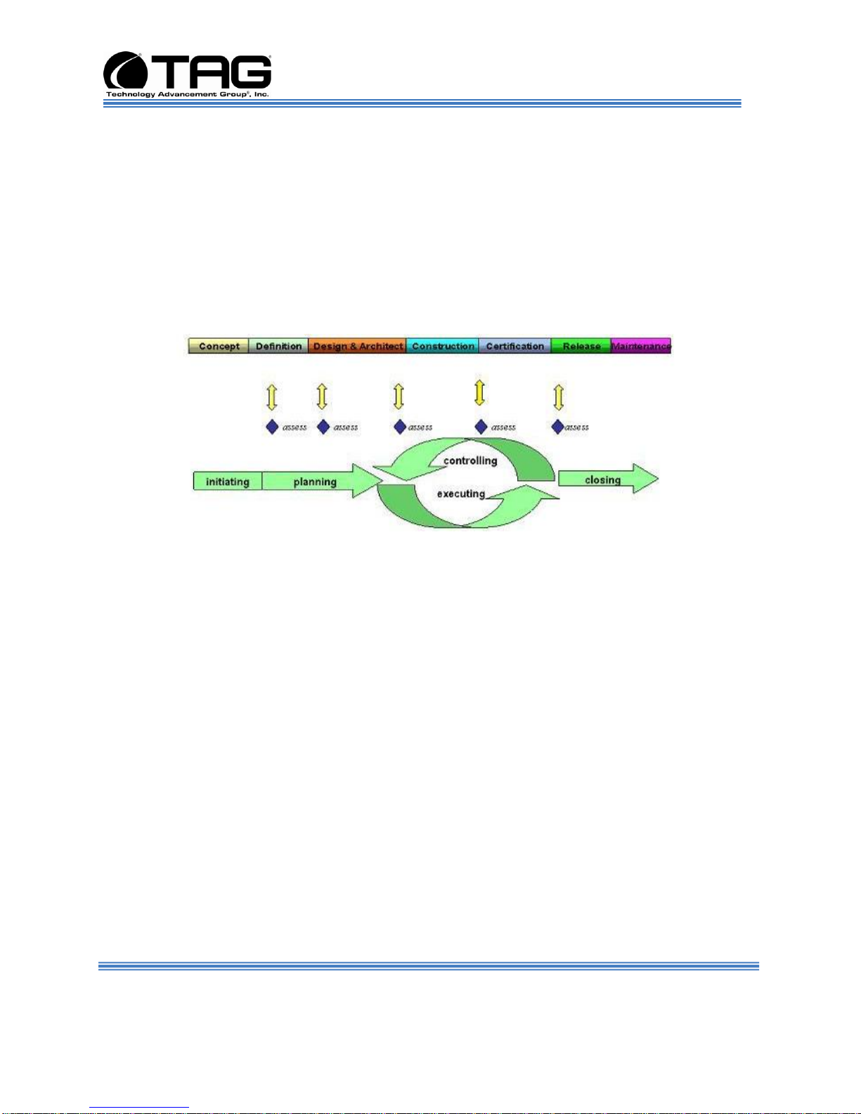
TAG’s world-class Program Management discipline models the renowned methodologies of the
Project Management Institute (PMI) to ensure successful completion of the task at hand. Our
Program Managers (PMs) serve as the voice of the customer – driving requirements to which the
rest of TAG’s organization answers. As an explicit tenet of TAG’s corporate mission statement,
the PMs not only track cost, schedule, and technical compliance throughout a project’s period of
performance, but also ensure the customer is supported well beyond it.
Document Number: 275-MNL-002 Page 5 of 84
Version 1.0. 08/25/2010
SV-2000-IX
Page 6

Date
Version Number
Updated By
Description of
Changes
08/25/2010
1.0
Alan Huckerby
Author
Operations Manual
Document Revision History
Document Number: 275-MNL-002 Page 6 of 84
Version 1.0. 08/25/2010
SV-2000-IX
Page 7

Operations Manual
3 About This Manual
3.1 Scope and Audience
This manual provides information on the Model
SV-2000-IX server. The Model SV-2000-IX
Server/Workstation allows for up to 2 cores in a
2U chassis as well as up to 4GB of RAM. SV2000-IX server features Core 2 Duo processor
to maximize processing performance, while
reducing power dissipation.
The Model SV-2000-IX is ideal for transit case
and deployable situations where such high
density computing minimizes size, weight, and
power.
3.1.1 Organization:
This manual is divided into the following
chapters and appendix:
Chapter 1 Cautions and Warnings when
handling the SV-2000-IX Server/Workstation.
Chapter 2 provides detailed information on the
external and internal server components.
Chapter 3 provides procedures for replacing
hot-swappable and LRU components, as well
as for replacing or adding system memory.
Document Number: 275-MNL-002 Page 7 of 84
Version 1.0. 08/25/2010
SV-2000-IX
Page 8

Operations Manual
Table of Contents
Contents
1 Copyright © 2009 Technology Advancement Group (TAG) .................................................... 2
1.1 Trademarks........................................................................................................................ 2
2 About TAG ............................................................................................................................. 3
2.1 Summary of Qualifications ................................ ................................................................ 3
2.2 Core Competences ............................................................................................................. 4
2.2.1 Engineering ................................................................................................................. 4
2.2.2 Manufacturing and Integration ..................................................................................... 4
2.2.3 Lifecycle Management ................................................................................................ . 5
3 About This Manual.................................................................................................................. 7
3.1 Scope and Audience .......................................................................................................... 7
3.1.1 Organization: ................................ ............................................................................... 7
4 Safety Instructions ................................................................................................................... 13
4.1 Types of warnings used in this manual............................................................................... 13
4.1.1 Safety Symbols and Labels .......................................................................................... 13
4.1.2 Conventions ................................................................................................................. 13
5 Server Overview...................................................................................................................... 16
5.1 Product Information ........................................................................................................... 16
5.2 Model SV-2000-IX Server/Workstation ............................................................................. 16
5.2.1 Specifications .............................................................................................................. 17
5.2.2 Additional specifications .............................................................................................. 17
5.2.3 Server Highlights ......................................................................................................... 18
5.2.4 SV-2000-IX Server ...................................................................................................... 18
5.2.5 I/O Connectors............................................................................................................. 19
5.3 Server Components ........................................................................................................... 19
5.3.1 Motherboard Model and Type ...................................................................................... 19
5.4 SV-2000-IX Server Board ................................................................................................. 20
5.4.1 Specifications .............................................................................................................. 21
5.5 System Memory ................................................................................................................ 22
5.5.1 Identifying System Memory......................................................................................... 22
5.6 Standard Server Components ............................................................................................. 22
5.6.1 Power Supply .............................................................................................................. 22
6 Procedures ................................................................ ............................................................... 25
6.1 Server Startup .................................................................................................................... 25
6.2 Server Shutdown ............................................................................................................... 25
6.3 Identifying Server Components Using Device Manager ..................................................... 25
6.4 Working with Device Properties ................................................................ ........................ 29
6.5 Installing and Removing Hardware in Windows ................................................................ 32
Document Number: 275-MNL-002 Page 8 of 84
Version 1.0. 08/25/2010
SV-2000-IX
Page 9

Operations Manual
6.5.1 Using the Add New Hardware Wizard ......................................................................... 33
6.6 Installing Legacy Peripherals ............................................................................................. 35
6.6.1 Removing Legacy Peripherals ...................................................................................... 35
6.7 TAG Approved BIOS ........................................................................................................ 39
6.7.1 Common BIOS Settings ............................................................................................... 39
6.7.2 BIOS Configuration for SV-2000-IX ........................................................................... 44
6.7.3 RAID Configuration .................................................................................................... 63
6.8 Upgrading Memory and Replacing Components ................................................................ 75
6.8.1 Preventing Static Electricity ......................................................................................... 75
6.9 Power Supply Cable Retention Bracket Installation ........................................................... 76
6.10 Replacing a Hard Drive ..................................................................................................... 79
6.10.1 300GB SAS Hard Drive ............................................................................................ 79
6.11 Removing the Server Cover ............................................................................................... 80
6.12 Adding or Replacing System Memory ............................................................................... 80
6.12.1 Install system memory. .............................................................................................. 81
7 APPENDIX CDW ................................................................................................................... 82
Document Number: 275-MNL-002 Page 9 of 84
Version 1.0. 08/25/2010
SV-2000-IX
Page 10

Operations Manual
List of Figures
Figure 5-1 SV-2000-IX Server/Workstation. ........................................................................ 17
Figure 5-2 SV-2000-IX Server/Workstation Components and Connectors. (Front View).
................................................................................................................................................. 18
Figure 5-3 I/O Connectors (Rear View)................................................................................ 19
Figure 5-4 Server Board ........................................................................................................ 20
Figure 6-1 Control Panel. ...................................................................................................... 27
Figure 6-2 System Properties. .............................................................................................. 27
Figure 6-3 Device Manger. .................................................................................................... 28
Figure 6-4 Device Manager. .................................................................................................. 30
Figure 6-5 Properties Dialog Box. ......................................................................................... 31
Figure 6-6 Control Panel. ...................................................................................................... 34
Figure 6-7 Add Hardware Wizard. ........................................................................................ 35
Figure 6-8 Control Panel. ...................................................................................................... 36
Figure 6-9 System Properties. .............................................................................................. 37
Figure 6-10 Device Manager. ................................................................................................ 38
Figure 6-11 BIOS Setup. ....................................................................................................... 44
Figure 6-12 Quiet Boot Disable Screen. .............................................................................. 45
Figure 6-13 Main Page Screen. ............................................................................................ 45
Figure 6-14 Advanced Feature Screen. ............................................................................... 46
Figure 6-15 Delay Prior to Thermal. ..................................................................................... 47
Figure 6-16 Advanced BIOS Features Screen. ................................................................... 48
Figure 6-17 Advance Screen. ............................................................................................... 48
Figure 6-18 Mass Storage Controller Configuration Screen. ............................................. 49
Figure 6-19 Mass Storage Controller Configuration Screen. ............................................. 50
Figure 6-20 Serial Port Configuration Screen...................................................................... 51
Figure 6-21 Serial Port Configuration Screen...................................................................... 52
Figure 6-22 USB Configuration Screen................................................................................ 53
Figure 6-23 USB Configuration Screen.. ............................................................................. 54
Figure 6-24 PCI Configuration Screen. ................................................................................ 55
Figure 6-25 System Acoustic and Performance Configuration Screen. ........................... 55
Figure 6-26 Integrated Peripherals Screen.......................................................................... 56
Figure 6-27 Onboard Device Screen. ................................................................................... 57
Figure 6-28 Boot Options Screen. ........................................................................................ 58
Figure 6-29 Integrated Peripherals Screen.......................................................................... 58
Figure 6-30 IBA GE Slot 0501 v1245. Screen. .................................................................... 59
Figure 6-31 Integrated Peripherals Screen.......................................................................... 60
Figure 6-32 SATA O MATSHITADVD Ram UJ-8755 Screen. ........................................... 61
Figure 6-33 Boot Manager Screen. ...................................................................................... 61
Figure 6-34 Save and Reset Popup Menu Screen. ............................................................ 62
Figure 6-35 RAID 11. ................................ ............................................................................. 63
Document Number: 275-MNL-002 Page 10 of 84
Version 1.0. 08/25/2010
SV-2000-IX
Page 11

Operations Manual
Figure 6-36 Management Menu Screen. ............................................................................. 64
Figure 6-37 New Configuration Screen. ............................................................................... 64
Figure 6-38 Proceed Screen. ................................................................................................ 65
Figure 6-39 Select Drives Screen. ........................................................................................ 65
Figure 6-40 Select Drives Screen. ........................................................................................ 66
Figure 6-41 Set Configurable Arrays Screen. ...................................................................... 67
Figure 6-42 Set Configurable Arrays Screen. ...................................................................... 67
Figure 6-43 Virtual Drive(s) Configured Screen .................................................................. 68
Figure 6-44 New Configuration Screen. ............................................................................... 68
Figure 6-45 New Configuration Screen ................................................................................ 69
Figure 6-46 New Configuration Screen. ............................................................................... 69
Figure 6-47 Management Menu Screen. ............................................................................. 70
Figure 6-48 Virtual Driver(s) Configured Screen. ................................................................ 71
Figure 6-49 Initialize Screen. ................................................................................................ . 71
Figure 6-50 Installation Screen. ............................................................................................ 72
Figure 6-51 Exit Screen. ........................................................................................................ 73
Figure 6-52 Reboot the System Screen. ................................................................ .............. 74
Figure 6-53 Grounding Wrist Strap ....................................................................................... 75
6-54 300GB SAS Hard Drive. ............................................................................................... 79
Figure 7-1 CDW ASSY-2U IX ............................................................................................... 83
List of Tables
Table 5-1 Server Board Specifications. ................................................................................ 21
Document Number: 275-MNL-002 Page 11 of 84
Version 1.0. 08/25/2010
SV-2000-IX
Page 12

Operations Manual
Chapter 1
Cautions and Warnings.
Electronically distributed. Subject to user discretion when printed.
Document Number: 275-MNL-002 Page 12 of 84
Version 1.0. 08/25/2010
SV-2000-IX
Page 13
DANGER
WARNING
CAUTION
These warnings and cautions indicate
situations or practice that might result in
property damage
Operations Manual
4 Safety Instructions
4.1 Types of warnings used in this manual
Read this manual thoroughly, paying special attention to
the cautions and warnings.
4.1.1 Safety Symbols and Labels
4.1.2 Conventions
4.1.2.1 Important Messages
4.1.2.2 Warnings
Document Number: 275-MNL-002 Page 13 of 84
Version 1.0. 08/25/2010
Important messages appear where
mishandling of components is possible or when
work orders can be misunderstood. These
messages also provide vital information
associated with other aspects of system
operation. The word “important” is written as
“IMPORTANT,” both capitalized and bold and
is followed by text in italics. The italicized text
is the important message.
Warnings appear where overlooked details
may cause damage to the equipment or result
SV-2000-IX
Page 14

Operations Manual
in personal injury. Warnings should be taken
seriously. Warnings are easy to recognize. The
word “warning” is written as “WARNING,” both
capitalized and bold and is followed by text in
italics. The italicized text is the warning
message.
4.1.2.3 Cautions
Cautionary messages should also be heeded
to help you reduce the chance of losing data or
damaging the system. Cautions are easy to
recognize. The word “caution” is written as
“CAUTION,” both capitalized and bold and is
followed by text in italics. The italicized text is the
cautionary message.
4.1.2.4 Notes
Notes inform the reader of essential but noncritical information. These messages should be
read carefully as any directions or instructions
contained therein can help you avoid making
mistakes. Notes are easy to recognize. The
word “note” is written as “NOTE,”
Document Number: 275-MNL-002 Page 14 of 84
Version 1.0. 08/25/2010
SV-2000-IX
Page 15

Operations Manual
Chapter 2
Model SV-2000-IX Server.
Electronically distributed. Subject to user discretion when printed.
SV-2000-IX
Document Number: 275-MNL-002 Page 15 of 84
Version 1.0. 08/25/2010
Page 16
Operations Manual
5 Server Overview
5.1 Product Information
This chapter provides an introductory overview
of the TAG family of tactical servers. TAG
servers are highly customizable; the specific
components vary depending on the mission
requirements. Your system may contain
components not described in this chapter. For
detailed information on these components,
refer to the manufactures website or contact
TAG Technical Support at
tech.support@tag.com.
TAG's tactical servers combine Intel® Model
SV-2001-THS® technology with state-of-the-art
mechanical, thermal and electrical engineering
to create customized systems that perform
above and beyond end user or program
specifications.
5.2 Model SV-2000-IX Server/Workstation
Document Number: 275-MNL-002 Page 16 of 84
Version 1.0. 08/25/2010
SV-2000-IX
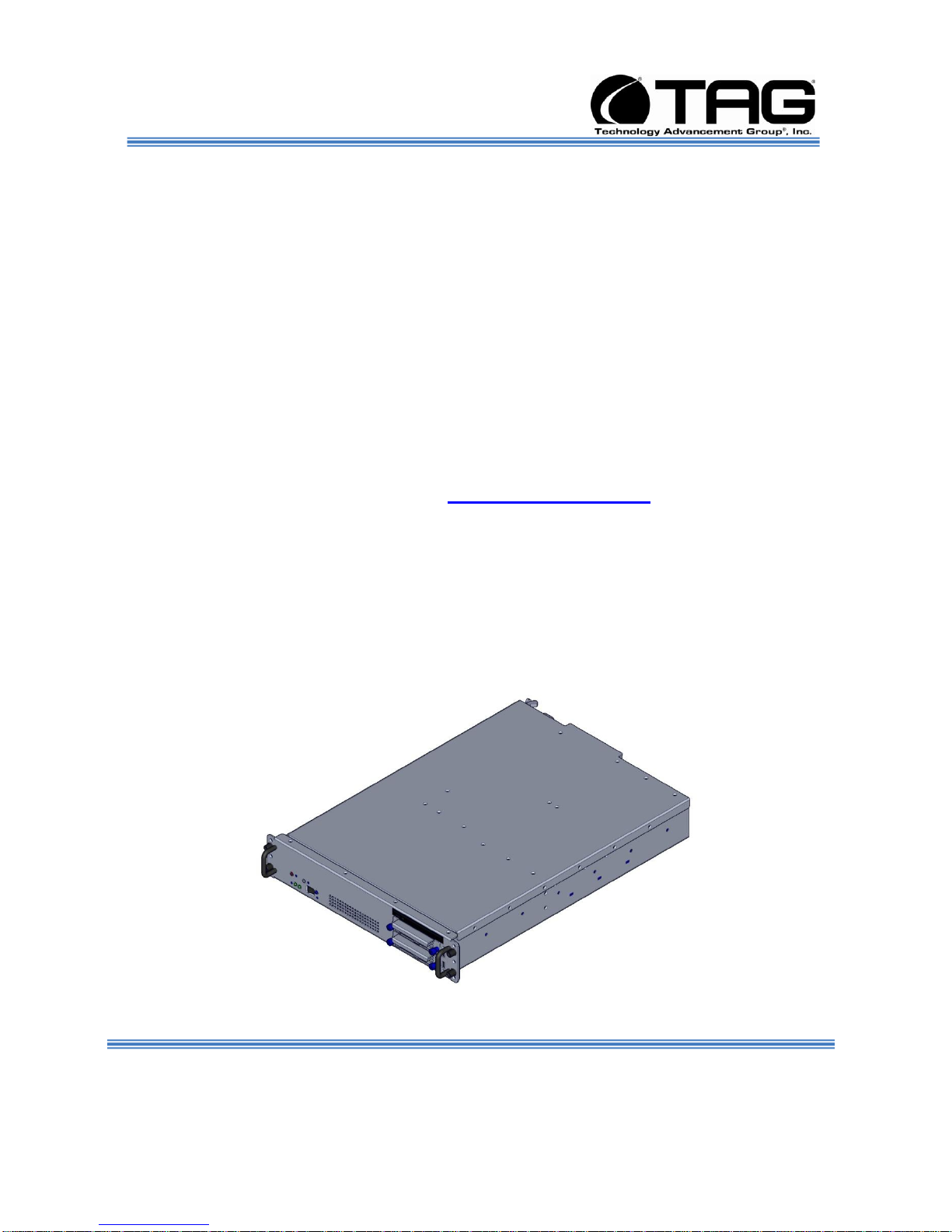
Page 17

Operations Manual
Figure 5-1 SV-2000-IX Server/Workstation.
5.2.1 Specifications
Chassis & power supply:
2U Heavy-duty, .090inch Aluminum rack-mount
chassis.
Chassis is designed to EIA-310-D Standards.
3.469”H x 19”W x 19.6”D.
Cooling system developed specifically for
harsh environments.
Front accessible on/off switche.
Processor & Cache:
Multi-Core Intel® Xeon® processor
32GB ECC FBDIMMs (8 DIMMs).
System Components:
4GB DDRZ RAM.
(2) 300GB removable (SAS) hard drives with
rugged metal carriers and receivers.
(6) External USB 2.0 Ports (6 Front).
(1) Serial Port.
(2) 10/100/1000 Ethernet Ports.
(1) VGA PORT
(2).PS2 Ports (Mouse, Keyboard).
LP Slot Loading DVD-RW/CD-RW Drive.
5.2.2 Additional specifications
Total Weight: 16,8lbs.
Input voltage range for Voltage (115V) is
100Vac to 120Vac range.
Input voltage range for Voltage (230V) is
200Vac to 240Vac range.
Max Input frequency range is 63hz. Nominal 50
to 60 hertz. Min 47Htz.
Document Number: 275-MNL-002 Page 17 of 84
Version 1.0. 08/25/2010
Max operating power is 460 watts.
SV-2000-IX
Page 18
Operations Manual
Inrush current at 115VAC is 8 amps max
Inrush current at 230VAC is 4 amps max
Operating Temperature Range. 0°C – 45°C
Non-Operating Temperature Range. -40°C –
70°C.
Operating Humidity Range. 20% - 90% RH
(Non Condensing).
Non-Operating Range. 5% - 95% RH (Non
Condensing).
5.2.3 Server Highlights
The SV-2000-IX is unlike any other server that
is currently on the market. The Model SV2000-IX is ideal for use in deployable situations
where the product’s compact size, high density
computing, minimized size, weight, and power
make for a highly portable, rugged and reliable
system.
Contains an intelligent fan controller
(acoustically optimized, environmentally
aware).
Small-form factor chassis made of
environmentally protected aluminum chassis.
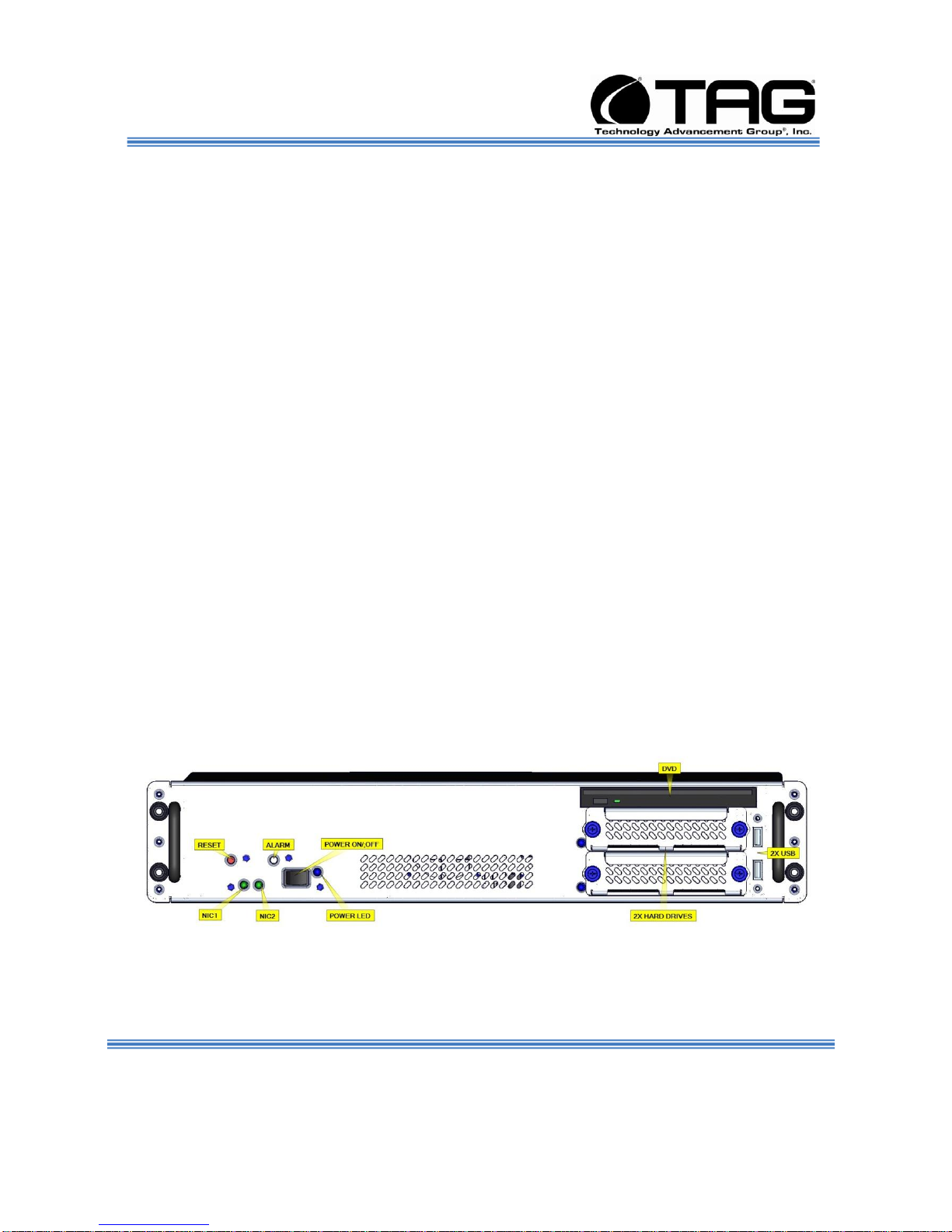
5.2.4 SV-2000-IX Server
Figure 5-2 SV-2000-IX Server/Workstation Components and Connectors. (Front View).
Document Number: 275-MNL-002 Page 18 of 84
Version 1.0. 08/25/2010
SV-2000-IX
Page 19
Operations Manual
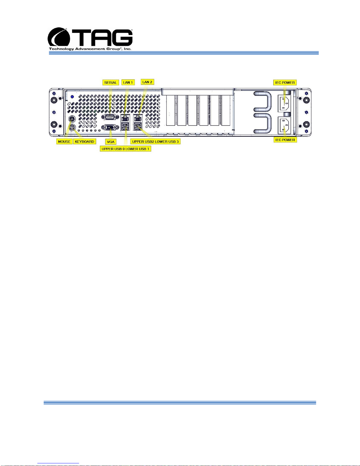
5.2.5 I/O Connectors
Figure 5-3 I/O Connectors (Rear View).
5.3 Server Components
This section provides an overview of the most
common components installed in TAG tactical
servers. Information is also provided on how to
identify specific components within your server.
For detailed information on the specific
components installed in your server, refer the
manufactures website.
5.3.1 Motherboard Model and Type
The version of an Intel server motherboard can
be determined by decoding the last three digits
of the board part number.
For example: For the product C44686-703, the
number following the "-" is as follows:
7 = Fabrication (FAB) Number
03 = Revision 3.
The board part number can be found on the
motherboard. The board part number can also
be determined by using Intel Server
Management software.
SV-2000-IX
Document Number: 275-MNL-002 Page 19 of 84
Version 1.0. 08/25/2010
Page 20
Operations Manual
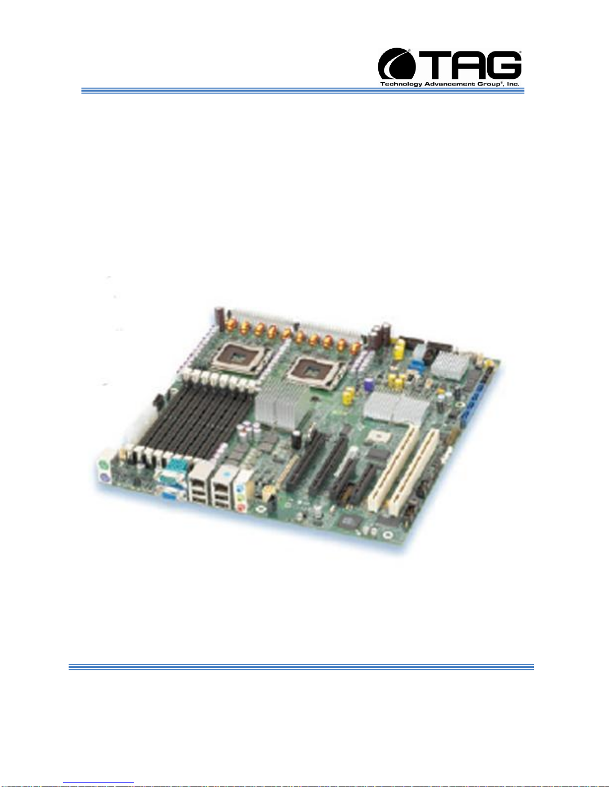
5.4 SV-2000-IX Server Board
High performance server board for maximum
reliability and manageability. The Intel® Server
Board S5000PSL has optional hardware RAID
via Intel® Integrated Server RAID delivers
added reliability, excellent data protection, and
advanced data management. The S5000PSL
optimizes performance and cost by integrating
key features, and supports a variety of chassis
configurations..
Document Number: 275-MNL-002 Page 20 of 84
Version 1.0. 08/25/2010
Figure 5-4 Server Board
SV-2000-IX
Page 21
Processor
Multi-Core Intel® Xeon® processor
System memory
Memory capacity
32GB ECC FBDIMMs (8 DIMMs)
Integrated on-board
Chipset
Intel® Chipset 5000P
Intel® Server
Network
Connections
Dual Intel® Gigabit Ethernet connections (Intel® 82563EB
Network)
Integrated
Graphics
ATI* with 16MB memory
Integrated storage support
Integrated ATA
One channel supporting up to two IDE devices
Integrated SATA
Intel® Server Board S5000PSL (SASR)
Two SATA ports with support for RAID 0, 1, 10 and optional
AXXRAKSW5 for RAID 51
SAS
Intel® Server Board S5000PSL (SASR) 4-Port LSI* 1064e SAS
controller with Intel® Embedded RAID Technology II providing
RAID 0, 1, 10 and optional AXXRAKSW5 for RAID 5
I/O
PCI
2 x PCI Express* x8
2 x PCI Express x4 (x8 Connectors)
1 x PCI-X 100/133 MHz
1 x PCI-X 100 MHz
Operations Manual
5.4.1 Specifications
Table 5-1 Server Board Specifications.
SV-2000-IX
Document Number: 275-MNL-002 Page 21 of 84
Version 1.0. 08/25/2010
Page 22

Operations Manual
5.5 System Memory
The type and amount of system memory, or
RAM (random access memory), on your server
depends on the motherboard installed and how
it was configured.
5.5.1 Identifying System Memory
Refer to your Motherboard Model and Type.
Once you have identified the motherboard,
TAG technical support can assist you in
determining the type and amount of system
memory in your system. See “Contacting
information on TAG on back page of this
manual for information on how to contact
Technical Support.
5.6 Standard Server Components
5.6.1 Power Supply
For information on replacing or upgrading your
system memory, refer to “Adding and
Replacing System Memory on page 50.”
The following sections provide information on
the standard system components installed on
TAG servers
AC input Power supply with an Input AC
Voltage Range of 115 Vrms nominal.
Input Power Line Frequency
The system shall operate over the input power
frequency range of 60 Hz nominal.
Power Connector
The AC input power connector is IEC 320.
Document Number: 275-MNL-002 Page 22 of 84
Version 1.0. 08/25/2010
SV-2000-IX
Page 23

Operations Manual
WARNING
Power supplies contain dangerous
voltages. Before attempting to work on any
power supply always unplug the device and
drain the power source by turning the
server on after the power supply has been
disconnected. Failure to follow these
instructions could result in serious injury
due to electrical shock.
.
Document Number: 275-MNL-002 Page 23 of 84
Version 1.0. 08/25/2010
SV-2000-IX
Page 24

Operations Manual
Chapter 3
Procedures.
Electronically distributed. Subject to user discretion when printed.
Document Number: 275-MNL-002 Page 24 of 84
Version 1.0. 08/25/2010
SV-2000-IX
Page 25

Operations Manual
6 Procedures
The procedures within this Chapter contain
relevant information to ensure your Model SV2000-IX Server/Workstation maintains its
maximum performance potential.
6.1 Server Startup
1. Check to make sure that all the cables are
seated and connected correctly to the back of
the unit such as keyboard, mouse, monitor
VGA cable and both power cables.
2. Then Press the power switch ON to start the
computer (power switch is located in the front
of the unit).
3. Once the unit starts, System will go thru Power
On self Test (POST) (no action is required at
this time).
4. At windows dialog box press Ctrl, Alt, Delete
at once to login.
5. Type in the correct user name and password
and then press enter to login.
6. Once the operator is logged on to the unit they
could use the computer as they wish.
NOTE: Assuming the server is not
connected to any network.
6.2 Server Shutdown
6.3 Identifying Server Components Using Device Manager
Document Number: 275-MNL-002 Page 25 of 84
Version 1.0. 08/25/2010
1. The operator needs save any data that is
needed to be saved and then close application
2. Once all data is save and applications are
closed, click on Start menu, select shutdown
and then click OK to shutdown the computer.
The Device Manager is one of Windows' most
useful diagnostic tools. It lets you see all of the
devices attached to your computer, and which
SV-2000-IX
Page 26

Operations Manual
resources they are each using. To access the
Device Manager do the following:
Document Number: 275-MNL-002 Page 26 of 84
Version 1.0. 08/25/2010
SV-2000-IX
Page 27
Operations Manual
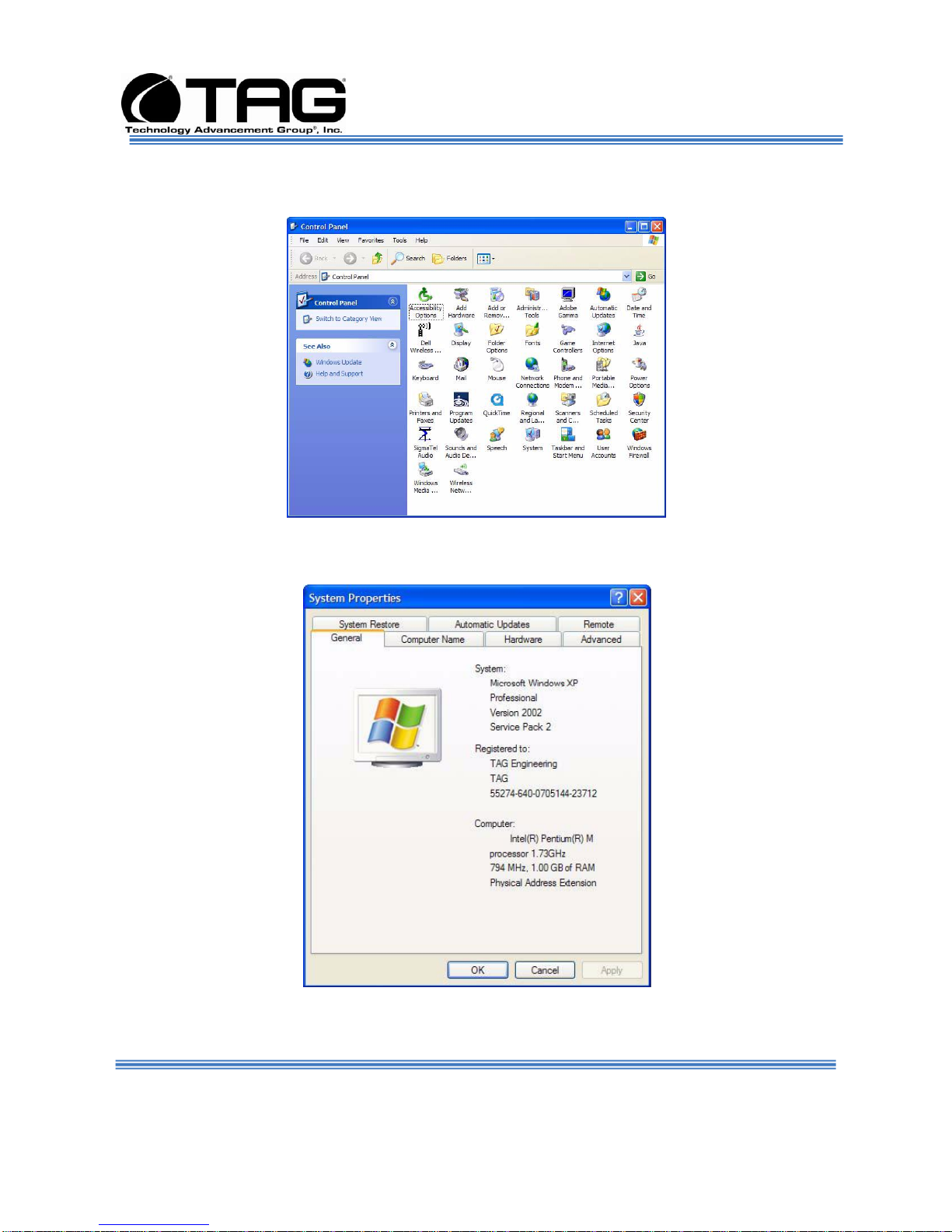
1. Click Start, point to Settings, and then click
Control Panel. (Figure 6-1).
Figure 6-1 Control Panel.
2. Double-click the System icon. (Figure 6-2).
Document Number: 275-MNL-002 Page 27 of 84
Version 1.0. 08/25/2010
Figure 6-2 System Properties.
SV-2000-IX
Page 28

Operations Manual
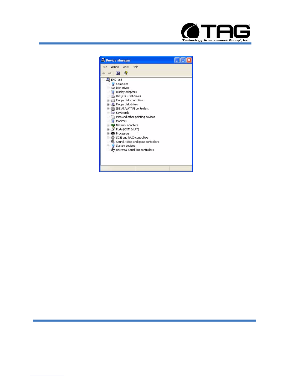
3. Click the Hardware tab, and then click the
Device Manager Button. (Figure 6-3).
Figure 6-3 Device Manger.
After opening Device Manager, you will see a
list of all the devices Windows detected on
your system. The Device Manager display is
recreated each time the computer is started, or
whenever a dynamic change to the computer
configuration occurs, such as addition of a new
device while the system is running.
NOTE: To include hidden devices, on the
View menu, click Show hidden devices. A
check mark next to Show hidden devices
indicates hidden devices are showing.
SV-2000-IX
Document Number: 275-MNL-002 Page 28 of 84
Version 1.0. 08/25/2010
Page 29

Operations Manual
Click it again to clear the check mark.
Hidden devices include non-PnP devices
and devices that have been physically
removed from the computer but have not
had their drivers uninstalled.
The devices shown represent the computer's
current hardware configuration information.
Any non-functioning devices are displayed with
an exclamation point, indicating that a problem
exists with the device; disabled devices are
displayed with a small red "x" over the icon.
You can use Device Manager to enable or
disable devices, troubleshoot devices, update
drivers, use driver rollback, and change
resources such as interrupt requests (IRQs)
assigned to devices.
6.4 Working with Device Properties
To display a device's properties do the
following:
1. Access the Device Manager as described in
steps 1 through 3. (Figure 6-4).
Document Number: 275-MNL-002 Page 29 of 84
Version 1.0. 08/25/2010
SV-2000-IX
Page 30
Operations Manual
Figure 6-4 Device Manager.
Document Number: 275-MNL-002 Page 30 of 84
Version 1.0. 08/25/2010
SV-2000-IX
Page 31
Operations Manual
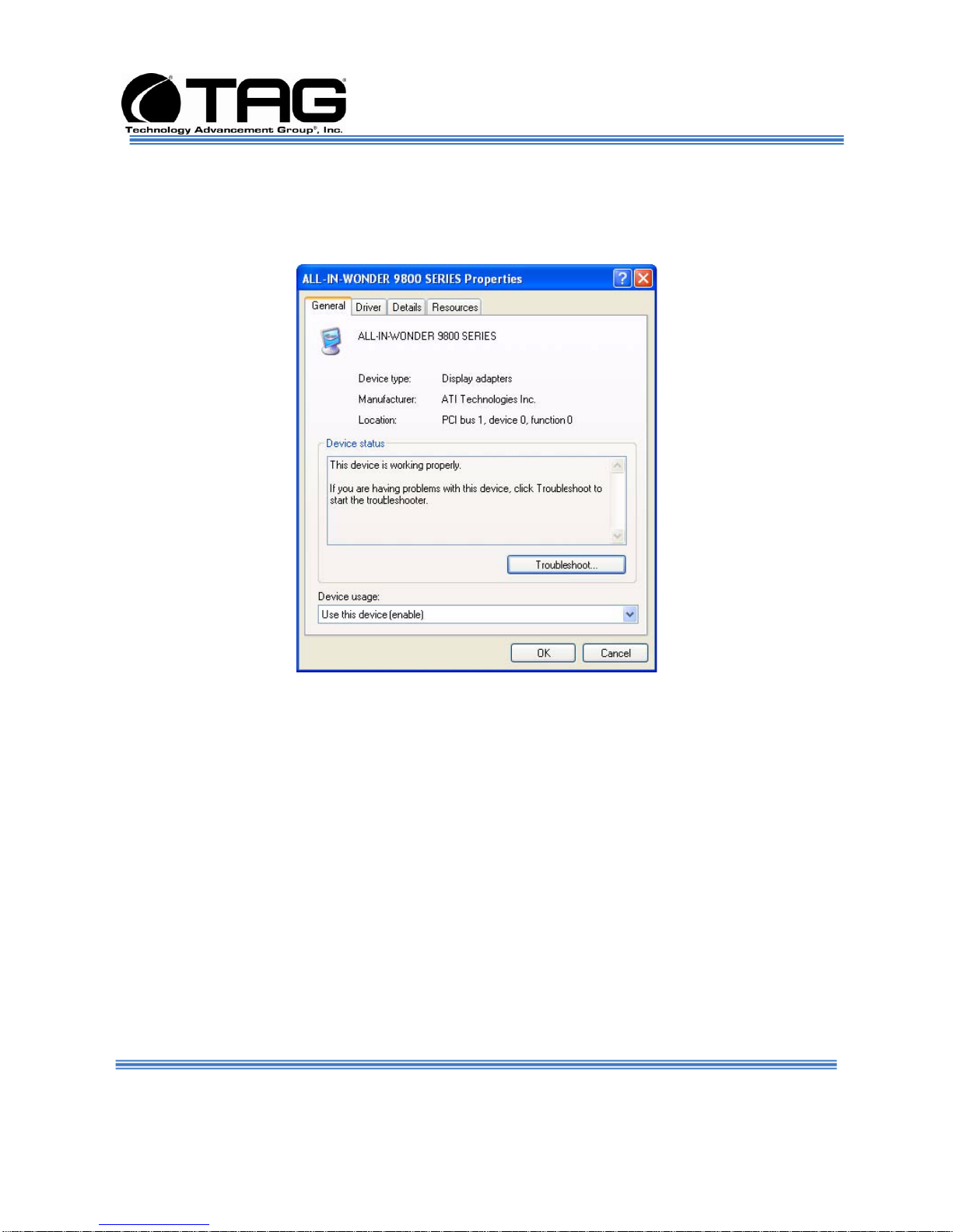
2. In the Device manager dialog box (Figure6-4),
double-click the device, or select the device
and then click the Properties toolbar button.
(Figure 6-5).
Figure 6-5 Properties Dialog Box.
In the device's Properties dialog box, there
might be several tabs. You can view the status
and configuration information, as well as the
device manufacturer, device type, and location
in the upper portion of the General tab.
The Device status box in the middle of the
General tab displays the status of the device,
including any errors. If the device has any
problems, the Device Status box briefly
describes the problem, and usually describes
the appropriate course of action to correct the
problem.
SV-2000-IX
Document Number: 275-MNL-002 Page 31 of 84
Version 1.0. 08/25/2010
Page 32

Operations Manual
3. Click Troubleshoot... to use the built-in
mechanisms for detecting the nature of the
problem.
Other tabs include the Driver tab, which
displays the details of the driver being used.
This tab also lets you update or uninstall the
driver. The Resources tab displays the
hardware resources being used. This tab
allows you to see and resolve any conflicts
caused by non-PnP devices. Along with these
tabs, some devices have additional advanced
settings or tabs for device-specific settings.
6.5 Installing and Removing Hardware in Windows
Plug and Play (PnP) is a standard that makes
installing new hardware devices easier. Prior to
PnP, installing new hardware meant finding
and installing peripheral drivers and making
sure the new device didn't conflict with another
device. Theoretically, if you have a computer
designed for PnP and are using a PnP
operating system (like Windows), installing a
printer, sound card, modem, or other peripheral
is a simple matter of plugging in the device.
It's not always quite this simple. Assuming you
are using a PnP computer, when you attach a
PnP device, you may see a message indicating
that Windows has recognized the new deviceeither immediately or the next time you start up
your system. If Windows needs a driver that is
not currently installed, you may at that point be
asked to insert a disk or the Windows CDROM. If you don't see a message but the
device appears to be working, you can assume
that everything is fine.
Document Number: 275-MNL-002 Page 32 of 84
Version 1.0. 08/25/2010
SV-2000-IX
Page 33

Operations Manual
6.5.1 Using the Add New Hardware Wizard
If the device is not working properly, try using the
Add New Hardware Wizard. To run this wizard, do
the following:
Document Number: 275-MNL-002 Page 33 of 84
Version 1.0. 08/25/2010
SV-2000-IX
Page 34
Operations Manual
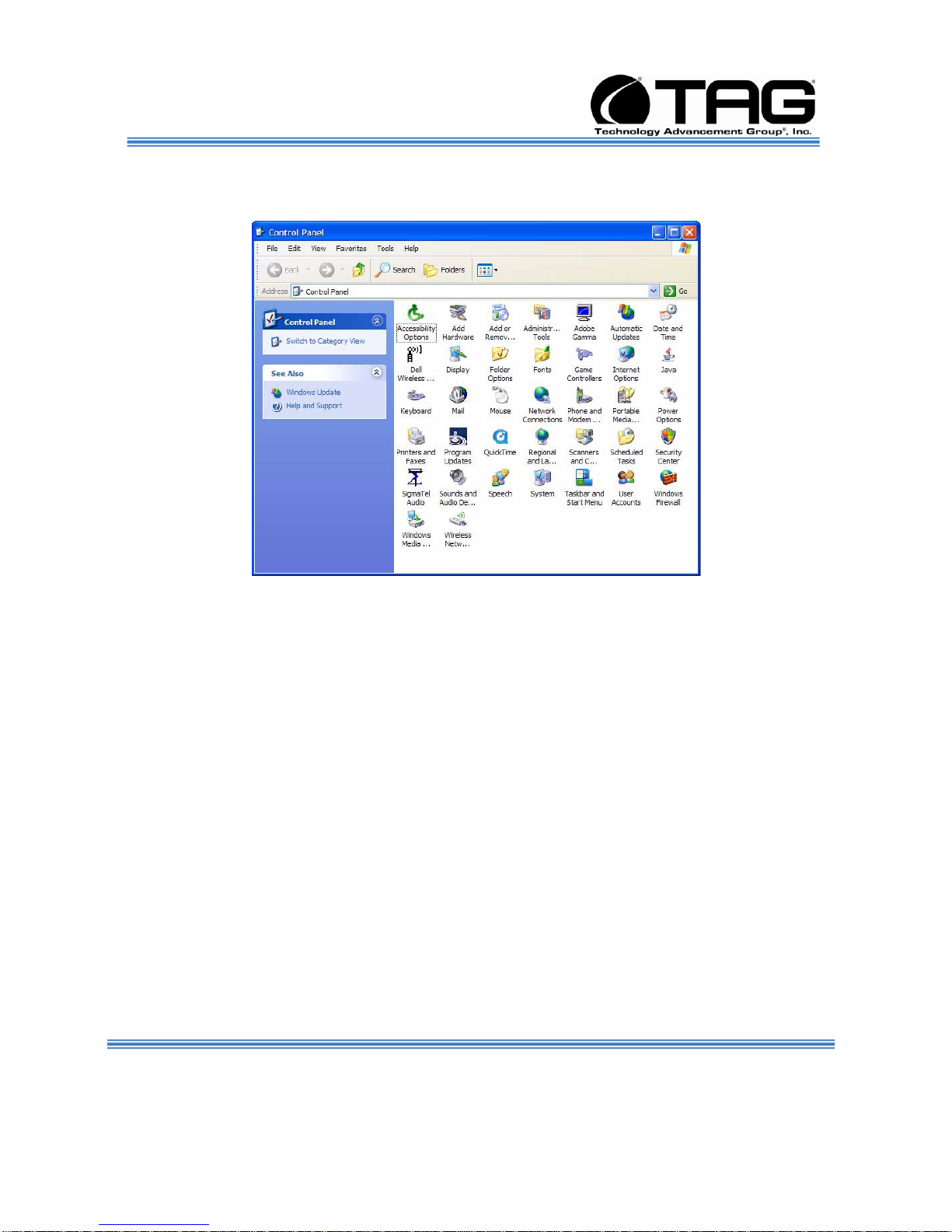
1. From the Start menu, point to Settings and then
click Control Panel. (Figure 6-6).
Figure 6-6 Control Panel.
2. Double-click the Add Hardware icon. (Figure
6-7).
Document Number: 275-MNL-002 Page 34 of 84
Version 1.0. 08/25/2010
SV-2000-IX
Page 35

Operations Manual
Figure 6-7 Add Hardware Wizard.
6.6 Installing Legacy Peripherals
When you install what Microsoft calls a legacy
peripheral, you will need to use the Add
Hardware Wizard,
NOTE: The term legacy refers to anything
that's no longer on the cutting edge.
6.6.1 Removing Legacy Peripherals
When removing a legacy peripheral from your
system, you need to let Windows know that the
device is gone. This enables Windows to reuse the
resources (places in memory and internal
communications channels) that it previously
allocated to that device.
To tell Windows that you have removed a legacy
device, perform the following steps:
Document Number: 275-MNL-002 Page 35 of 84
Version 1.0. 08/25/2010
SV-2000-IX
Page 36

Operations Manual
1. From the Start menu, point to Settings and then
click Control Panel. (Figure 6-8).
Figure 6-8 Control Panel.
2. Double-click the System icon. (Figure 6-9).
Document Number: 275-MNL-002 Page 36 of 84
Version 1.0. 08/25/2010
SV-2000-IX
Page 37

Operations Manual
Figure 6-9 System Properties.
3. Click the Hardware tab.
4. Click the Device Manager button. (Figure 6-
10).
Document Number: 275-MNL-002 Page 37 of 84
Version 1.0. 08/25/2010
SV-2000-IX
Page 38

Operations Manual
Figure 6-10 Device Manager.
5. Click the name of the item you have removed from
your system. If you don't see the item, look for a
category heading that describes the type of device
you removed, and then click the plus sign to its left
to display a list of items in that category.
6. From the Action menu, click Uninstall.
7. Click OK.
Document Number: 275-MNL-002 Page 38 of 84
Version 1.0. 08/25/2010
SV-2000-IX
Page 39

Operations Manual
6.7 TAG Approved BIOS
The BIOS (basic input/output system) is the
program stored on the CMOS that the server's
microprocessor uses to get the system started
after you turn it on. The BIOS also manages
data flow between the computer's operating
system and attached devices such as the hard
disk, video adapter, keyboard, and mouse.
CAUTION: The BIOS installed on your
server was loaded and tested with all the
devices initially installed in your system. If
you desire to have the BIOS updated,
consult TAG technical support in advance
as updates to your approved BIOS may
cause your system to become unstable or
inoperable.
6.7.1 Common BIOS Settings
Printer Parallel Port-Uni., Bi-directional, Disable, Enable, ECP, EPP
6.7.1.1 Printer Parallel Port Uni., Bi-Directional,
Disable, Enable, ECP, EPP.
Settings in the CMOS enable you to configure
a parallel port to use Enhanced Parallel Port
(EPP) or Enhanced Parallel Port (ECP). ECP.
EPP and ECP are bi-directional standards,
operate in 8-bit, and allow data transfer speed
of approximately 2 MB/s. Some of the main
differences are that ECP supports Direct
Memory Access (DMA) and data compression,
which enables higher transfer rates.
It is also possible to completely disable the
parallel port in the BIOS. Most BIOS' allow you
to set the DMA channel, when the port mode is
set to ECP.
Document Number: 275-MNL-002 Page 39 of 84
Version 1.0. 08/25/2010
SV-2000-IX
Page 40

Operations Manual
6.7.1.2 Com / Serial Port
Most personal computers have two serial ports.
In the BIOS you can assign
COM1/COM2/COM3/COM4 to serial port 1 or
2.
Most BIOS' also allow you to set the I/O and
IRQ but this is mostly done automatically.
6.7.1.3 Hard Drives
Most modern BIOS' allow automatic detection
of disk parameters. The settings can be
individually configured for the primary master
and slave device and the secondary master
and slave device. The following are some of
the primary settings that apply to hard drives
as well as CD/DVD-ROM drives, tape backup
drive, etc.
Common disk types are:
User-defined Cylinders, Heads, Sectors (CHS)
values.
Auto-automatically detects hard disks
parameters at every startup.
1-46-predefined combinations of CHS values.
CDROM-used for AT Attachment Packet
Interface (ATAPI) CD-ROM drives.
ARMD-used for ATAPI ZIP and LS 120 drives.
DVDROM.
Size - Determines the capacity of the drive CHS
values:
Number of Cylinders.
Number of Heads.
Number of Sectors.
SV-2000-IX
Document Number: 275-MNL-002 Page 40 of 84
Version 1.0. 08/25/2010
Page 41

Operations Manual
LBA (Large Block Addressing)-technology to
overcome the 528 MB limit.
6.7.1.4 Boot Sector Virus
A common setting related to hard drives. When
enabled, the BIOS issues a warning
message/beep if an attempt is made to write to
the boot sector or partition table of a hard disk.
6.7.1.5 Memory
Parity adds an extra bit (odd or even) to the 8bit data-string to ensure data integrity in
memory modules. Its successor, ECC,
provides improved data integrity by adding
information about individual bits.
6.7.1.6 Boot Sequence
This setting is used to control the order that the
BIOS uses during the boot process to look for
a boot device from which to load the operating
system. For example:
CD.
Floppy.
Hard Disk.
6.7.1.7 Date and Time
The Date and Time is set in the BIOS, stored in
CMOS, and maintained by CMOS battery.
6.7.1.8 Passwords
In most cases a user (startup) password and a
supervisor (setup) password can be set in the
CMOS. When a Setup password is required,
the computer will prompt for it when you try to
Document Number: 275-MNL-002 Page 41 of 84
Version 1.0. 08/25/2010
SV-2000-IX
Page 42

Operations Manual
access the BIOS setup. When a Startup
password is configured, the computer will
prompt for it at every startup.
The CMOS password can be reset by
shortening the "CMOS restore to factory
defaults jumper" or by temporarily removing the
CMOS battery.
6.7.1.9 Plug and Play BIOS
Today's BIOS' are Plug and Play (PnP)-aware.
This means they are able to automatically
assign resources such as IRQ and DMA to
PnP devices.
Information about PnP devices is stored in a
separate area of non-volatile CMOS memory,
called the Extended System Configuration
Database (ESCD). Both the PnP BIOS and the
operating system can access this area and
communicate with each other about resource
settings assigned to PnP devices as well as
non-PnP devices. For example, when a fixed
interrupt request (IRQ) is manually assigned to
a particular device using Device Manager,
Windows will write this information to the
ESCD on shutdown thereby preventing the
BIOS from assigning the same IRQ to a PnP
device at startup.
Document Number: 275-MNL-002 Page 42 of 84
Version 1.0. 08/25/2010
You can also reserve IRQs for non-PnP
devices in the CMOS setup, this will prevent
the BIOS from assigning these reserved
resources to PnP devices, a common example
is a legacy sound card that needs IRQ 5.
SV-2000-IX
Page 43

Operations Manual
6.7.1.10 Power Management
Modern motherboards provide Advanced
Configuration and Power Management
Interface (ACPI) settings such as wake-up,
power button function and standby/suspend
timers. These functions are configured in the
CMOS Setup.
Document Number: 275-MNL-002 Page 43 of 84
Version 1.0. 08/25/2010
SV-2000-IX
Page 44

Operations Manual
6.7.2 BIOS Configuration for SV-2000-IX
1. On the Main page, Select Quiet Boot. Press
ENTER. (Figure 6-11).
Figure 6-11 BIOS Setup.
2. On the Quiet Boot Popup Menu Select
Disabled. Press ESCAPE to return to the main
screen. (Figures 6-12).
Document Number: 275-MNL-002 Page 44 of 84
Version 1.0. 08/25/2010
SV-2000-IX
Page 45

Operations Manual
Figure 6-12 Quiet Boot Disable Screen.
3. On the Main page, Scroll down and select Post
Error Pause. No Change. Verify Date and
Time are correct. Press RIGHT arrow to move
to Advanced Screen. (Figures 6-13).
Figure 6-13 Main Page Screen.
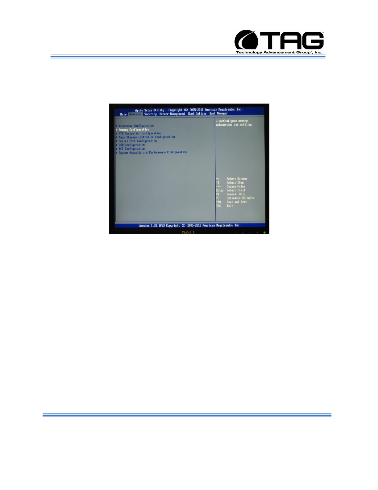
4. On Main Page Screen Use the Right Arrow to
move to the Advanced Feature on the main
Document Number: 275-MNL-002 Page 45 of 84
Version 1.0. 08/25/2010
SV-2000-IX
Page 46

Operations Manual
tool bar. Select Processor Configuration then
press ENTER. (Figure 6-14).
Figure 6-14 Advanced Feature Screen.
Document Number: 275-MNL-002 Page 46 of 84
Version 1.0. 08/25/2010
SV-2000-IX
Page 47

Operations Manual
5. Scroll down to Intel Virtualization
Technology. Hit ENTER. (Figure 6-15).
Figure 6-15 Delay Prior to Thermal.
6. On the Popup Menu, Select ENABLE. Press
ESCAPE. (Figure 6-16)
Document Number: 275-MNL-002 Page 47 of 84
Version 1.0. 08/25/2010
SV-2000-IX
Page 48
Operations Manual
Figure 6-16 Advanced BIOS Features Screen.
7. No changes for Memory Configuration and
ATA Controller Configuration. (Figure 6-17).
Figure 6-17 Advance Screen.
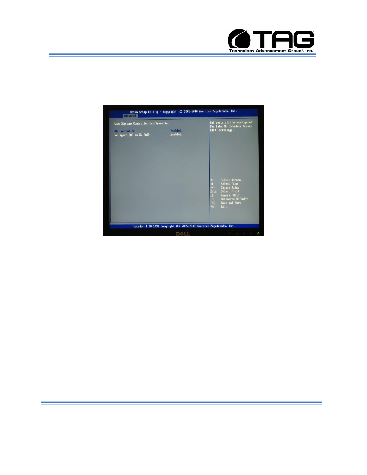
8. Scroll down and select Mass Storage
Controller Configuration. Press ENTER.
(Figure 6-18).
Document Number: 275-MNL-002 Page 48 of 84
Version 1.0. 08/25/2010
SV-2000-IX
Page 49

Operations Manual
Figure 6-18 Mass Storage Controller Configuration Screen.
Document Number: 275-MNL-002 Page 49 of 84
Version 1.0. 08/25/2010
SV-2000-IX
Page 50
Operations Manual
9. On the Mass Storage Controller
Configuration Screen select Advanced
Configure SAS as SW RAID. Select
ENABLED. Press ESCAPE. (Figure 6-19)
Figure 6-19 Mass Storage Controller Configuration Screen.
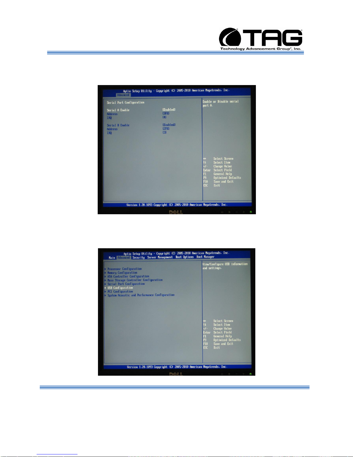
10. Select Serial Port Configuration. Press
ENTER. (Figure 6-20)
Document Number: 275-MNL-002 Page 50 of 84
Version 1.0. 08/25/2010
SV-2000-IX
Page 51

Operations Manual
Figure 6-20 Serial Port Configuration Screen.
Document Number: 275-MNL-002 Page 51 of 84
Version 1.0. 08/25/2010
SV-2000-IX
Page 52
Operations Manual
11. No Change for Serial Port Configuration
Press ESCAPE. (Figure 6-21)
Figure 6-21 Serial Port Configuration Screen.
12. Select USB Configuration. Press ENTER.
(Figure 6.22).
Document Number: 275-MNL-002 Page 52 of 84
Version 1.0. 08/25/2010
SV-2000-IX
Page 53

Operations Manual
Figure 6-22 USB Configuration Screen.
Document Number: 275-MNL-002 Page 53 of 84
Version 1.0. 08/25/2010
SV-2000-IX
Page 54

Operations Manual
13. No Change on the USB Configuration
Screen. Defaults Selected. Press ESCAPE..
(Figure 6-23)
Figure 6-23 USB Configuration Screen..
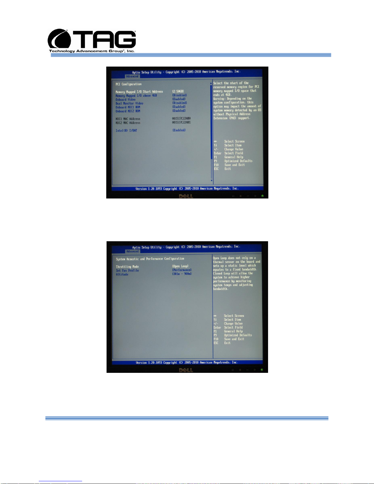
14. No Change on the PCI Configuration Screen.
Defaults Selected. Press ESCAPE. (Figure 6-
24)
Document Number: 275-MNL-002 Page 54 of 84
Version 1.0. 08/25/2010
SV-2000-IX
Page 55
Operations Manual
Figure 6-24 PCI Configuration Screen.
15. No Change on the System Acoustic and
Performance Configuration screen. Defaults
Selected. Press ESCAPE. (Figure 6-25)
Figure 6-25 System Acoustic and Performance Configuration Screen.
Document Number: 275-MNL-002 Page 55 of 84
Version 1.0. 08/25/2010
16. Scroll across on the Main Tool bar and select
SECURITY. No Changes. (Figure 6-26)
SV-2000-IX
Page 56

Operations Manual
Figure 6-26 Integrated Peripherals Screen.
Document Number: 275-MNL-002 Page 56 of 84
Version 1.0. 08/25/2010
SV-2000-IX
Page 57

Operations Manual
17. Scroll across on the Main Tool bar and select
Server management. No Changes. (Figure
6.27).
Figure 6-27 Onboard Device Screen.
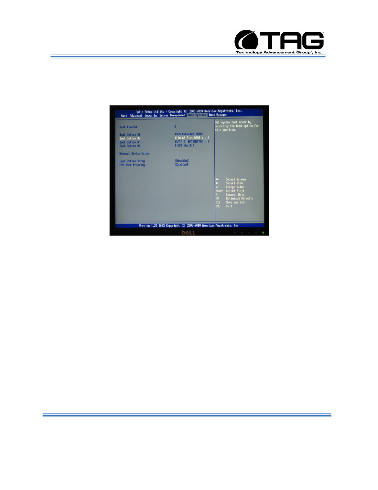
18. Scroll across on the Main Tool bar and select
Boot Options. Press ENTER. (Figure 6.28).
Document Number: 275-MNL-002 Page 57 of 84
Version 1.0. 08/25/2010
SV-2000-IX
Page 58
Operations Manual
Figure 6-28 Boot Options Screen.
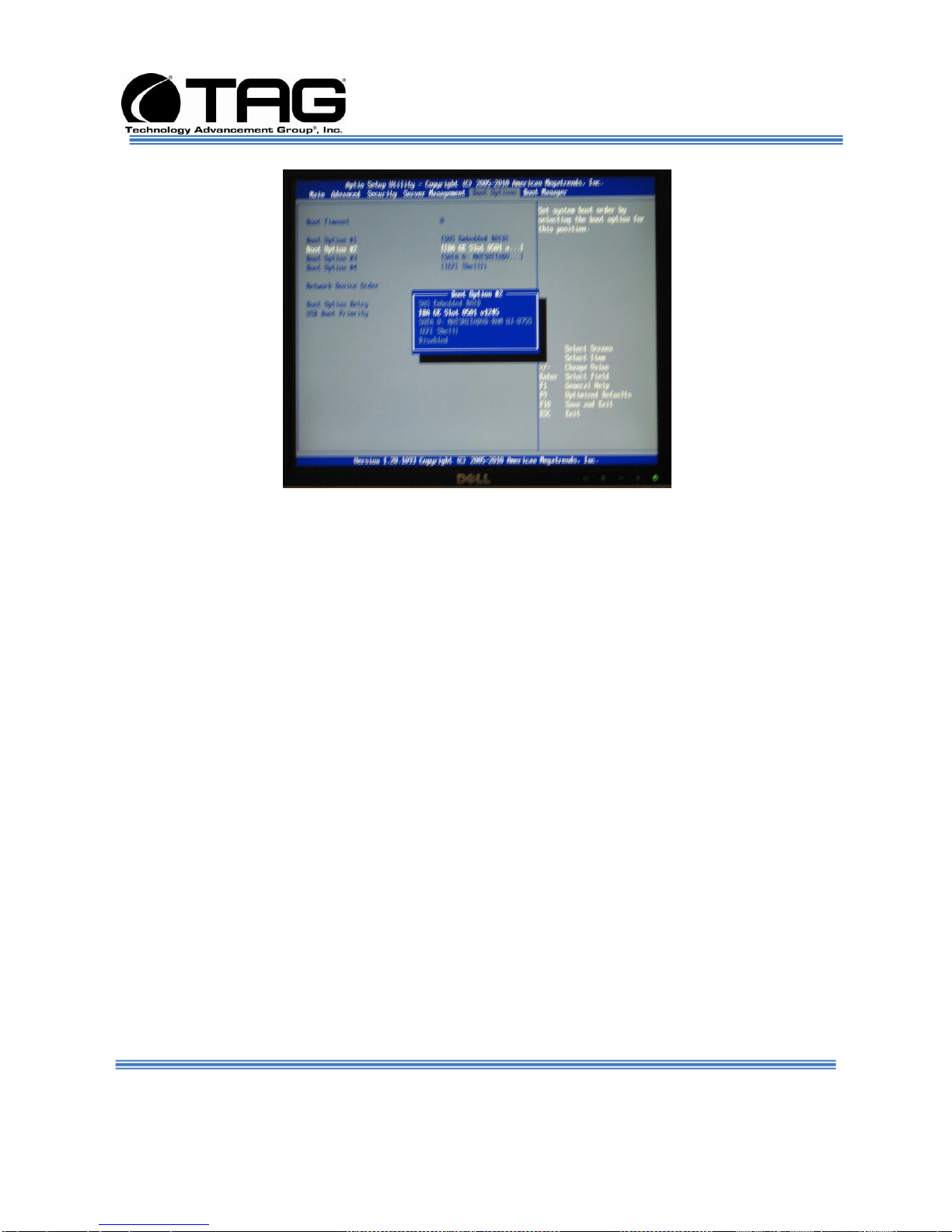
19. Scroll Down and select Boot Option #2. Press
ENTER. (Figure 6.29).
Figure 6-29 Integrated Peripherals Screen.
20. On the Popup Menu select IBA GE Slot 0501
v1245. Press ENTER. (Figure 6.30).. Press
ESCAPE to return to the Integrated
Peripherals Screen.
Document Number: 275-MNL-002 Page 58 of 84
Version 1.0. 08/25/2010
SV-2000-IX
Page 59
Operations Manual
Figure 6-30 IBA GE Slot 0501 v1245. Screen.
Document Number: 275-MNL-002 Page 59 of 84
Version 1.0. 08/25/2010
SV-2000-IX
Page 60

Operations Manual
21. On the Integrated Peripherals Screen scroll
down and select Boot Option #3. Press
ENTER. (Figure 6-31).
Figure 6-31 Integrated Peripherals Screen.
22. On the Popup Menu select SATA O
MATSHITADVD Ram UJ-8755. Press ENTER.
(Figure 6.30).. Press ESCAPE to return to the
Main Screen. . (Figure 6-32)
Document Number: 275-MNL-002 Page 60 of 84
Version 1.0. 08/25/2010
SV-2000-IX
Page 61

Operations Manual
Figure 6-32 SATA O MATSHITADVD Ram UJ-8755 Screen.
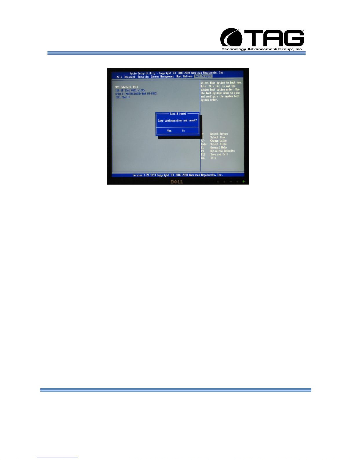
23. Scroll across on the Main Tool bar and select
Boot Manager Screen. No Change. Press
F10. (Figure 6-33)
Figure 6-33 Boot Manager Screen.
24. On the Save and Reset Popup Menu. Select
YES. Press Enter. (Figure 6-34).
Document Number: 275-MNL-002 Page 61 of 84
Version 1.0. 08/25/2010
SV-2000-IX
Page 62
Operations Manual
Figure 6-34 Save and Reset Popup Menu Screen.
Document Number: 275-MNL-002 Page 62 of 84
Version 1.0. 08/25/2010
SV-2000-IX
Page 63
Operations Manual
6.7.3 RAID Configuration
NOTE: For Software Configuration refer to “Redundant Generic Software Manual
(4GFC / SAS Host Interface)”. This Manual is placed on Web site:
tag.com/support/goodrich
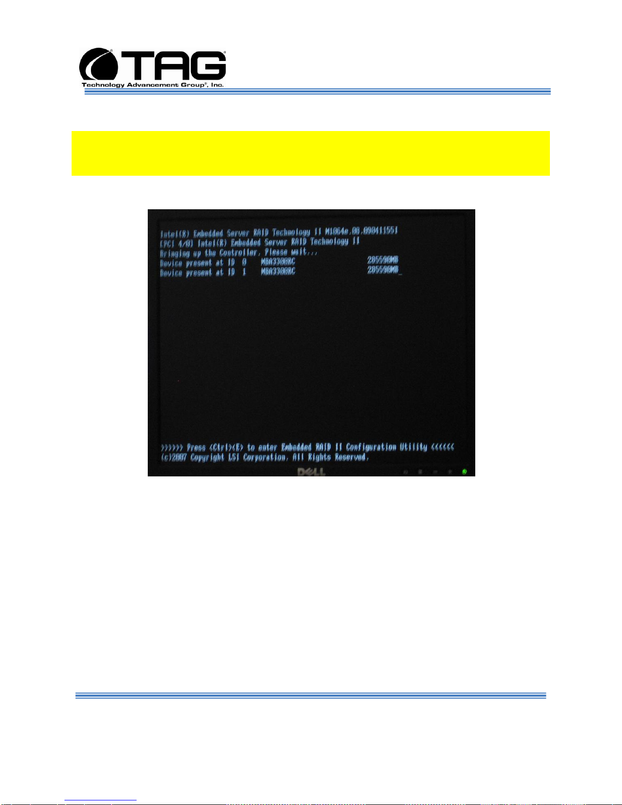
1. Enter BIOS then Press Ctrl E to enter RAID
11 Configuration Utility. (Figure 6-35).
Figure 6-35 RAID 11.
SV-2000-IX
Document Number: 275-MNL-002 Page 63 of 84
Version 1.0. 08/25/2010
Page 64
Operations Manual
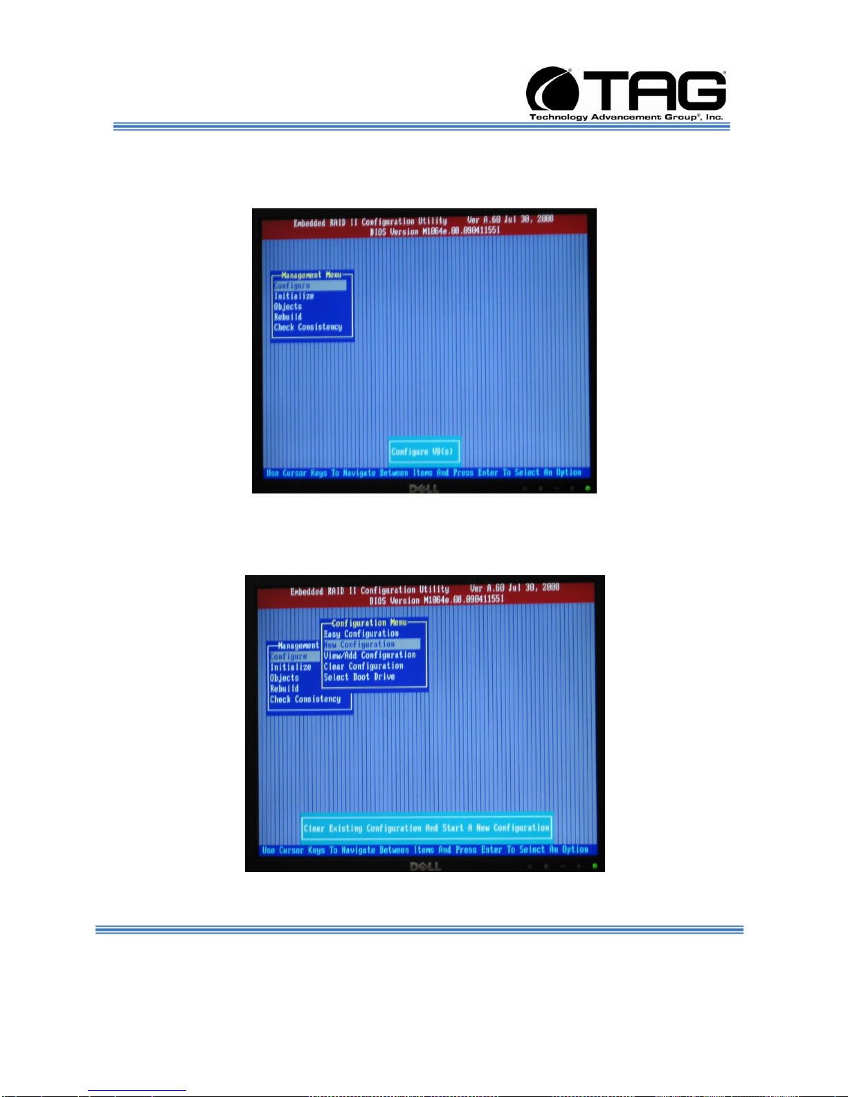
2. On the dropdown Management Menu Select
Configure and Press ENTER. (Figure 6-36).
Figure 6-36 Management Menu Screen.
3. Select New Configuration on the dropdown
menu. Press ENTER. (Figure 6-37).
Figure 6-37 New Configuration Screen.
Document Number: 275-MNL-002 Page 64 of 84
Version 1.0. 08/25/2010
SV-2000-IX
Page 65

Operations Manual
4. Select YES on the Proceed dropdown menu.
Press ENTER. (Figure 6-38).
Figure 6-38 Proceed Screen.
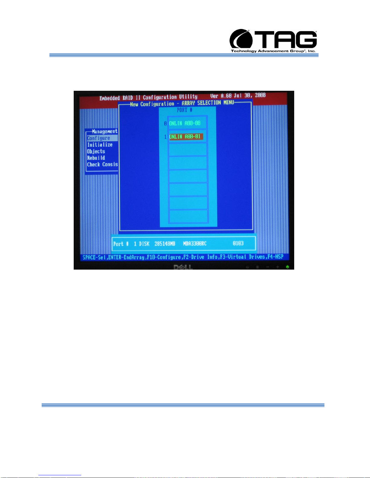
5. Press the Space Bar to select drives. (Figure
6-39 and Figure 6.40).
Figure 6-39 Select Drives Screen.
Document Number: 275-MNL-002 Page 65 of 84
Version 1.0. 08/25/2010
SV-2000-IX
Page 66
Operations Manual
6. Press the Space Bar to select drives. After
selection Press F10. (Figure 6-40).
Figure 6-40 Select Drives Screen.
SV-2000-IX
Document Number: 275-MNL-002 Page 66 of 84
Version 1.0. 08/25/2010
Page 67
Operations Manual
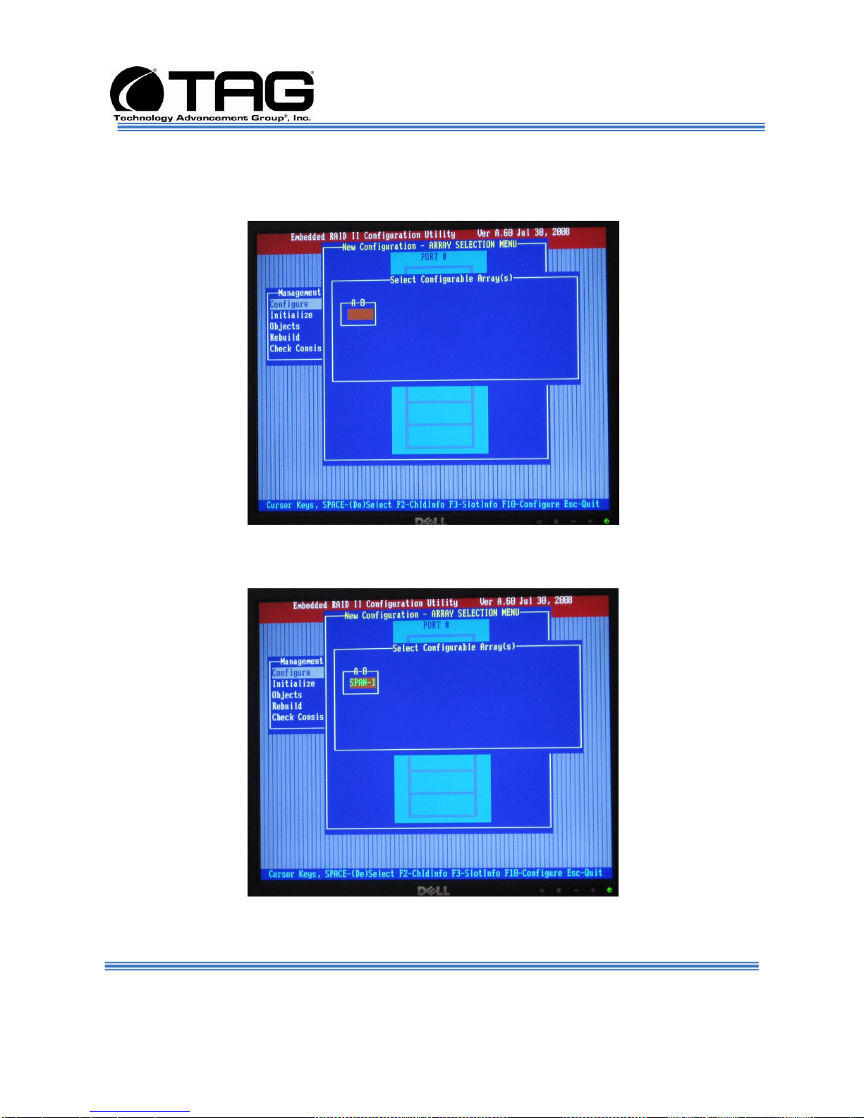
7. On the Set Configurable Arrays screen Press
Space Bar to accept. (Figure 6-41 and Figure
6.42).
Figure 6-41 Set Configurable Arrays Screen.
8. Accept Setting. Press F10. (Figure 6-42).
Figure 6-42 Set Configurable Arrays Screen.
Document Number: 275-MNL-002 Page 67 of 84
Version 1.0. 08/25/2010
SV-2000-IX
Page 68

Operations Manual
9. On the Virtual Drive(s) Configured screen.
Press ENTER.On the Dropdown Menu select
Accept. Press ENTER. (Figure 6-43).
Figure 6-43 Virtual Drive(s) Configured Screen
10. On the New Configuration screen. Scroll
down and select ONLIN-A00-01. Press
ENTER. (Figure 6-44).
Figure 6-44 New Configuration Screen.
Document Number: 275-MNL-002 Page 68 of 84
Version 1.0. 08/25/2010
SV-2000-IX
Page 69

Operations Manual
11. On the Popup Menu select New
Configuration. Press ENTER. . On the Popup
Menu select YES and Press ENTER. (Figure
6-45).
Figure 6-45 New Configuration Screen
12. Press ESCAPE. (Figure 6-46).
Figure 6-46 New Configuration Screen.
Document Number: 275-MNL-002 Page 69 of 84
Version 1.0. 08/25/2010
SV-2000-IX
Page 70
Operations Manual
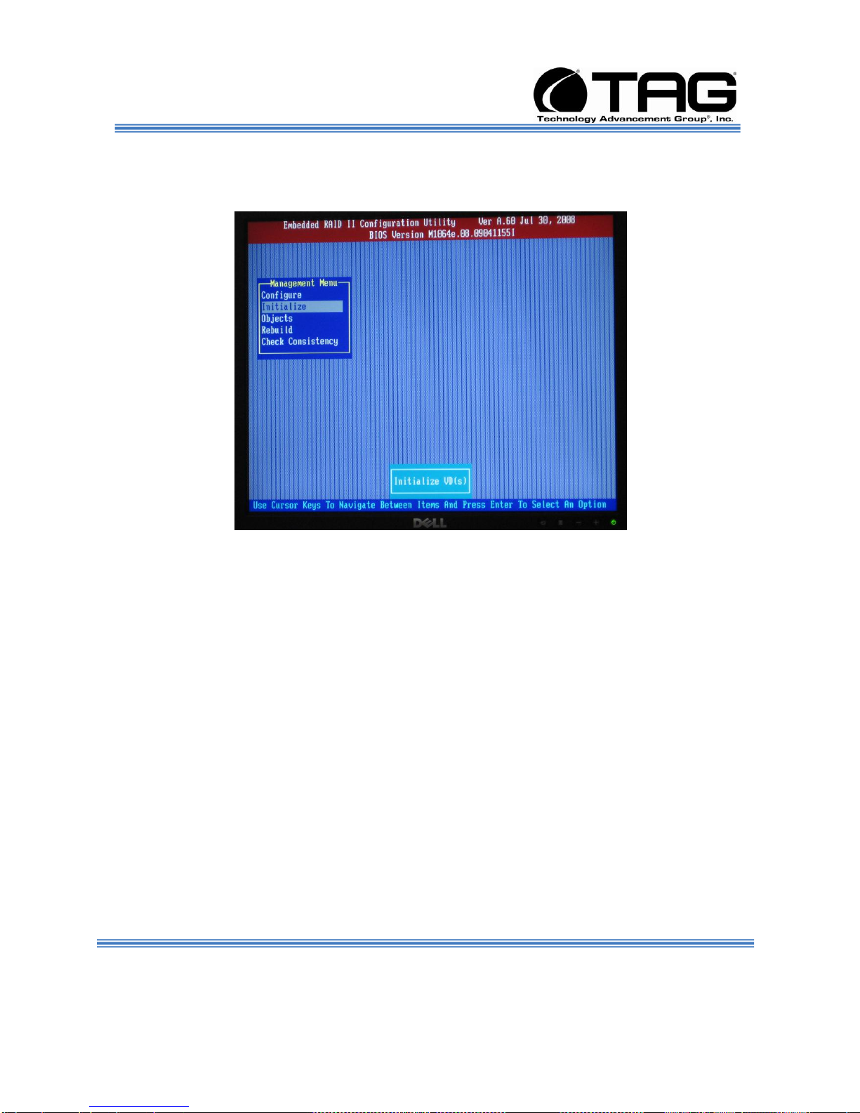
13. On the Management Menu scroll down to
Initialize. Press ENTER. (Figure 6-47).
Figure 6-47 Management Menu Screen.
14. On the Virtual Driver(s) Configured screen.
Press F10. (Figure 6-49).
Document Number: 275-MNL-002 Page 70 of 84
Version 1.0. 08/25/2010
SV-2000-IX
Page 71

Operations Manual
Figure 6-48 Virtual Driver(s) Configured Screen.
15. On the Initialize screen select YES. Press
ENTER. (Figure 6-49).
Figure 6-49 Initialize Screen.
Document Number: 275-MNL-002 Page 71 of 84
Version 1.0. 08/25/2010
SV-2000-IX
Page 72

Operations Manual
16. After installation is complete Press ESCAPE.
(Figure 6-50).
Figure 6-50 Installation Screen.
17. Select YES and press ENTER. (Figure 6-51).
Document Number: 275-MNL-002 Page 72 of 84
Version 1.0. 08/25/2010
SV-2000-IX
Page 73

Operations Manual
Figure 6-51 Exit Screen.
25. Reboot the System. (Figure 6-52).
Document Number: 275-MNL-002 Page 73 of 84
Version 1.0. 08/25/2010
SV-2000-IX
Page 74

Operations Manual
Figure 6-52 Reboot the System Screen.
Document Number: 275-MNL-002 Page 74 of 84
Version 1.0. 08/25/2010
SV-2000-IX
Page 75

Operations Manual
6.8 Upgrading Memory and Replacing Components
6.8.1 Preventing Static Electricity
This section provides procedures for replacing all
hot-swappable and LRU components, including
procedures for replacing or adding system memory.
The components inside your computer are
extremely sensitive to static electricity, also known
as electrostatic discharge (ESD). ESD can
permanently damage electrostatic dischargesensitive components in your server.
To prevent ESD damage, follow these guidelines
before opening the server case:
1. Turn off the server and unplug the power cord
before opening the case.
2. Wear a grounding wrist strap and attach it to a
bare metal part of the server, workbench, or other
grounded connection.
Document Number: 275-MNL-002 Page 75 of 84
Version 1.0. 08/25/2010
Figure 6-53 Grounding Wrist Strap
3. Do not insert any object into the vent holes on the
case or the power supply. Touch a bare metal
surface on the back of the computer, a bare metal
surface on your workbench, or other grounded
object before handing DIMMs or other components.
Before working with computer components,
follow these guidelines:
SV-2000-IX
Page 76

____1.0 :Initial Check Points
____1.1
VERIFY the Work Permit instructions
have been completed.
____1.2
VERIFY locks and tags are properly
attached to equipment.
____1.3
VERIFY all power is removed from
the Server.
____2.0 Install AC Retainer
Bracket:
____2.1
SV-2001-THS-Server. (Figure 6-72).
____2.4
Secure Power Supply Cable
Retention Bracket by the THREE
supplied screws. (Figure 6-74).
Operations Manual
Avoid static-causing surfaces such as carpeted
floors, plastic, and packing foam.
Remove components from their antistatic bags
only when you are ready to use them. Do not
lay components on the outside of antistatic
bags because only the inside of the bags
provide electrostatic protection. Always hold
memory modules and components by their
edges or their metal mounting brackets.
Avoid touching the edge connectors and
components on the cards. Never slide memory
modules or components over any surface.
6.9 Power Supply Cable Retention Bracket Installation
Document Number: 275-MNL-002 Page 76 of 84
Version 1.0. 08/25/2010
SV-2000-IX
Page 77
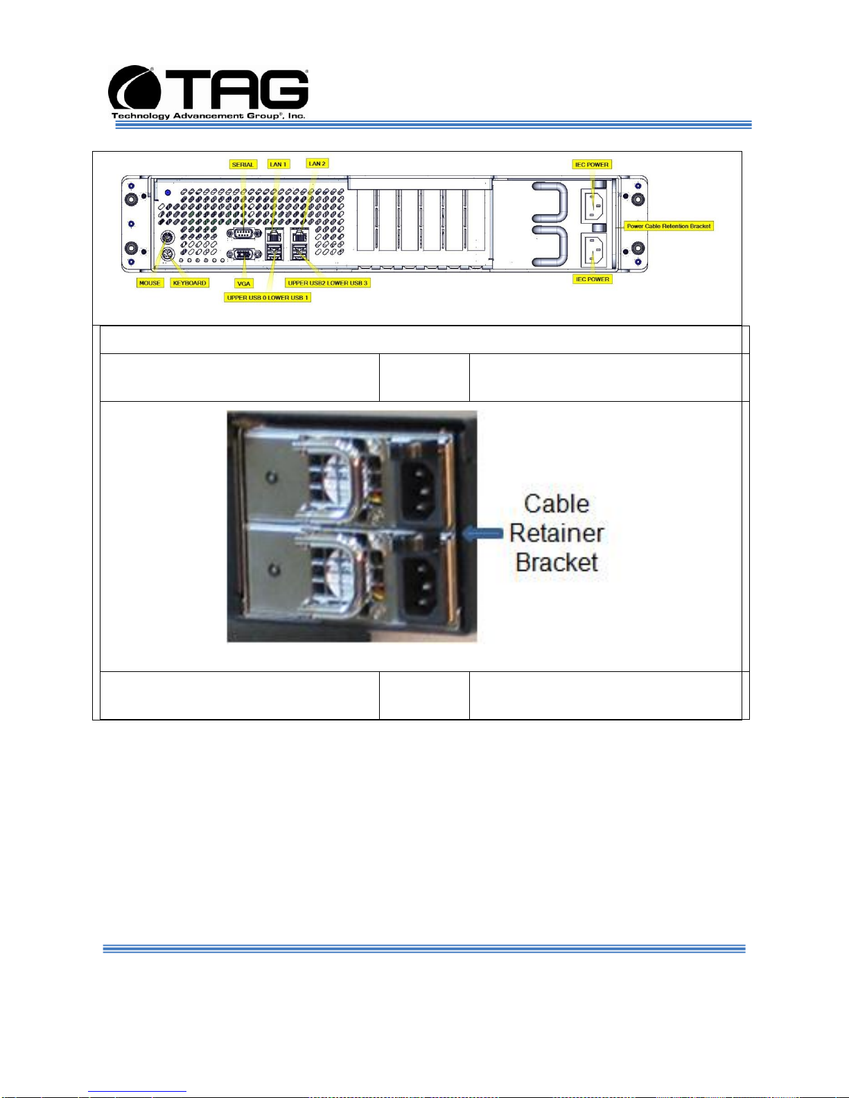
Figure 6.54 Secure Power Supply Cable Retention Bracket.
____2.2
Location of AC Cable Retainer
Bracket Slot. (Figure 6-55).
Figure 6-55 AC Cable Retainer Bracket Slot.
____2.3
AC Cable Retainer Bracket. (Figure
6-56).
Operations Manual
Document Number: 275-MNL-002 Page 77 of 84
Version 1.0. 08/25/2010
SV-2000-IX
Page 78
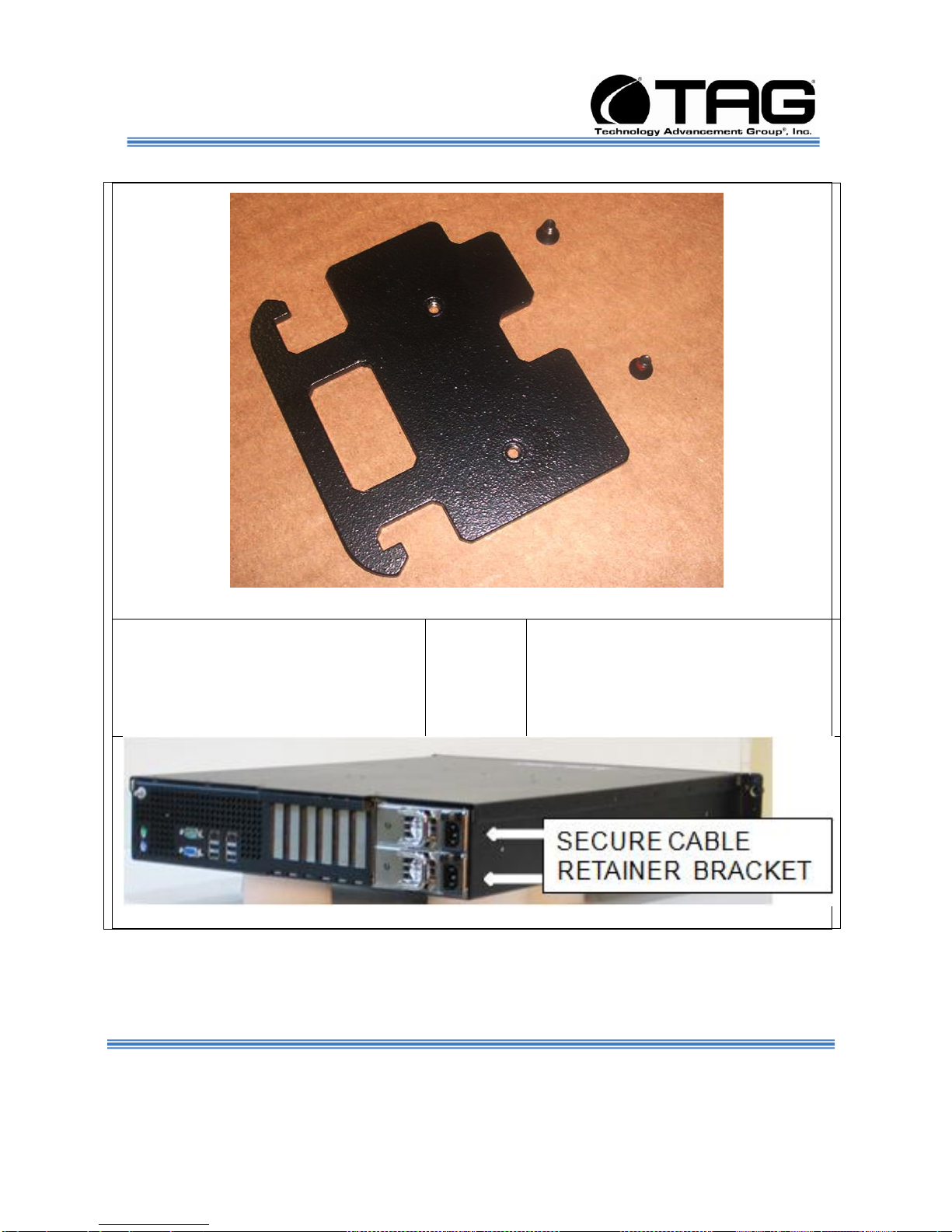
Figure 6-56 AC Cable Retainer Bracket.
____2-4
Slide AC Cable Retainer Bracket.
(Figure 6-56) Into AC Cable
Retainer Bracket Slot and Secure
AC Cable Retainer Bracket by the
two supplied screws Figure 6-57).
Figure 6-57 Slide AC Cable Retainer Bracket. Into AC Cable Retainer Bracket Slot.
Operations Manual
SV-2000-IX
Document Number: 275-MNL-002 Page 78 of 84
Version 1.0. 08/25/2010
Page 79
Operations Manual
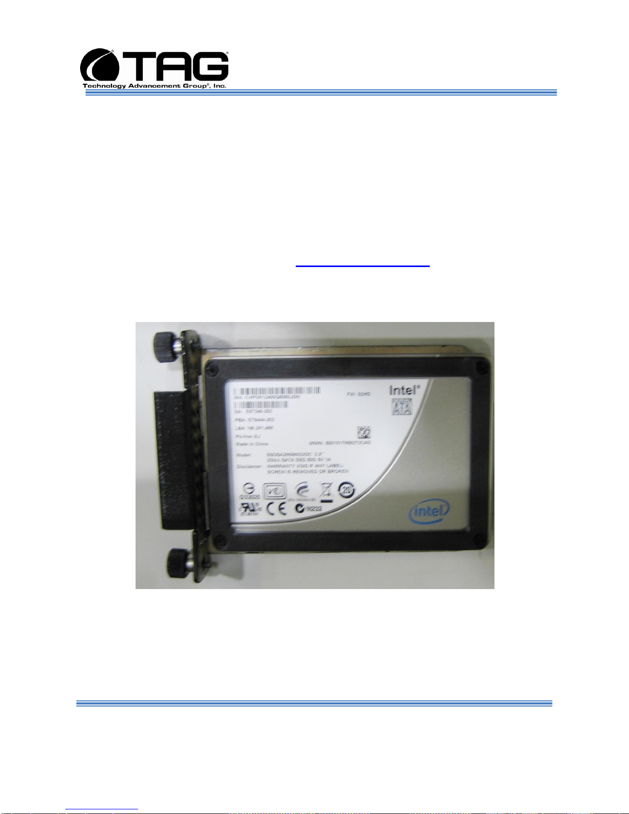
6.10 Replacing a Hard Drive
To remove the systems Hard Drive you need to
stop the hard drive and take it offline to remove
the logical software links to the hard drive, and
to reconfigure the file system so that it will
recognize the new drive. You will have to
reconfigure your application software.
Therefore it is strongly recommended that you
contact TAG Technical Support at
tech.support@tag.com before attempting to
exchange the hard drive. For more information
on contact information see Manual back page.
6.10.1 300GB SAS Hard Drive
Document Number: 275-MNL-002 Page 79 of 84
Version 1.0. 08/25/2010
6-54 300GB SAS Hard Drive.
SV-2000-IX
Page 80

Operations Manual
6.11 Removing the Server Cover
The location of the mounting screws securing
the server cover varies per server model. To
remove the cover, use a Phillips screwdriver to
remove all screws from the sides and top of the
cover.
NOTE: It is important to make note of the
location from which screws are removed
since different screw lengths may be used
to secure the cover.
CAUTION
It is not safe to operate TAG servers
without the cover in place. Failure to take
this precaution may result in personal
injury and system damage.
6.12 Adding or Replacing System Memory
This section lists the procedures for adding or
replacing system memory.
WARNING
Ensure that the system is powered-down
and all power sources have been
disconnected from the server prior to
removing or replacing system memory.
Failure to do so could result in serious
injury from electrical shock.
CAUTION
Printed circuit boards and hard drives
contain electronic components that are
Document Number: 275-MNL-002 Page 80 of 84
Version 1.0. 08/25/2010
SV-2000-IX
Page 81
Operations Manual
extremely sensitive to static electricity.
Ordinary amounts of static from your
clothes or the work environment can
destroy components. Do not touch the
components or any metal parts without
taking proper antistatic precautions.
AG's tactical servers combine Intel® Model SV2001-THS® technology with state-of-the-art
mechanical, thermal and electrical engineering
to create customized systems that perform
above and beyond end user or program
specifications. Our tactical servers are
designed to meet and exceed many MIL-STD
requirements to ensure survivability in the field.
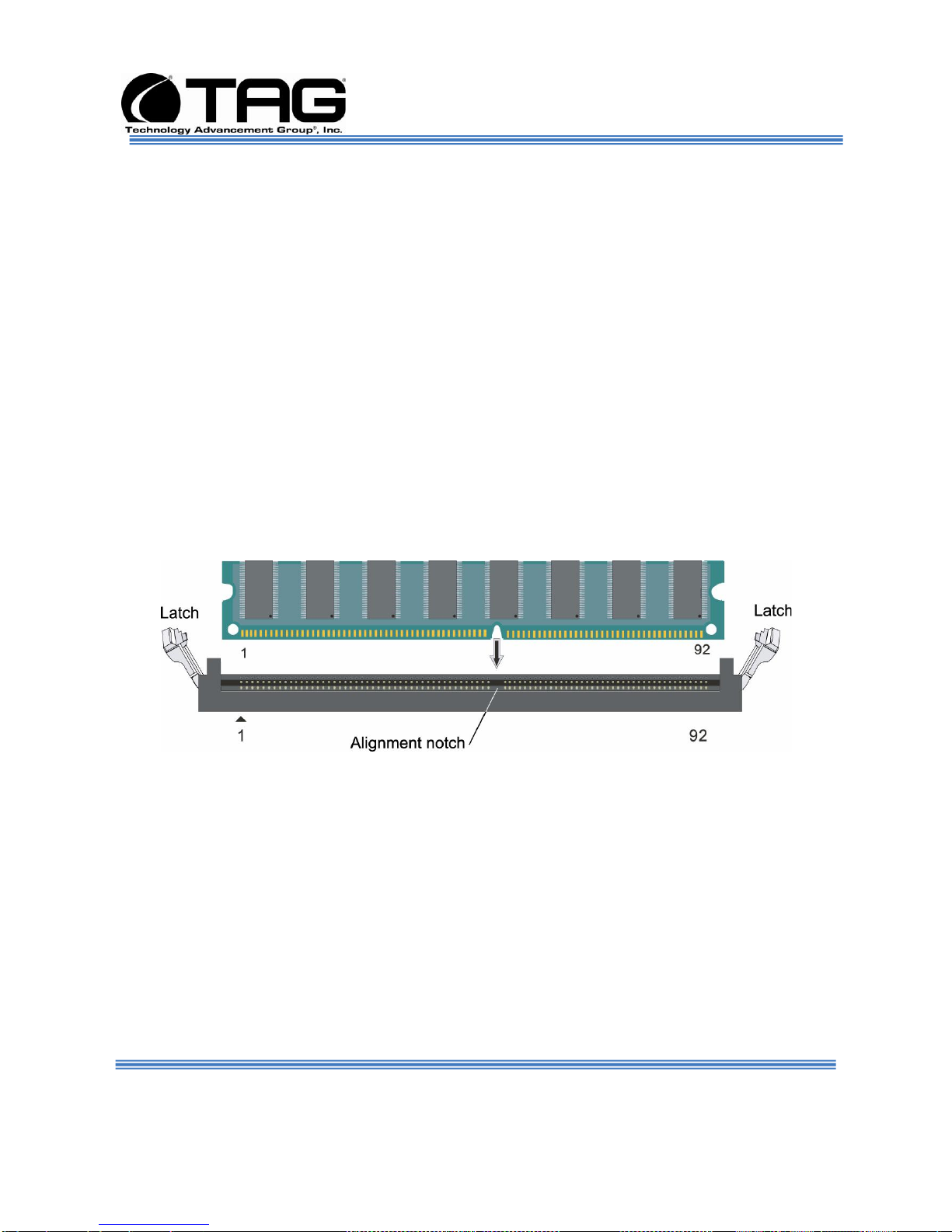
6.12.1 Install system memory.
Unlatch both DIMM socket levers, as shown in Figure 6-60.
Figure 6-60 DIMM Module Bank
1. Note the location of the alignment notch.
2. Align the notches on the new module with the
notches on the memory and press it firmly into
the bank.
NOTE: The tabs on the sides of the memory
module should secure the DIMM
automatically. When the DIMM locks into
place, you will hear a click.
Document Number: 275-MNL-002 Page 81 of 84
Version 1.0. 08/25/2010
SV-2000-IX
Page 82

Operations Manual
7 APPENDIX CDW
Document Number: 275-MNL-002 Page 82 of 84
Version 1.0. 08/25/2010
SV-2000-IX
Page 83

Chapter 3
SV-2000-IX Server
Part Number: 1008950 Page 83 of 84
Version 1.0. 07/12/10
Assembly 2U-IX
Figure 7-1 CDW ASSY-2U IX
Page 84

CONTACT
7.1.1
22355 TAG Way
Dulles, VA 20166
Tel: 1-800-824-7693
www.tag.com
Technical Support
USA 1-800-824-7693
Outside USA
While every precaution has been taken
to ensure the accuracy and completeness
of this literature. TAG assumes
no responsibility and disclaims and liability
for damage resulting from use of this information
or for any errors or omissions.
 Loading...