

Page 1

TAG
22355 TAG Way
Dulles, VA 20166
`
SV-1002-X2 Server
Operations Manual
282-MNL-009
P/N 1008826, 1009006, 1008871
Page 2

Operations Manual
1 Copyright © 2009 Technology Advancement Group (TAG)
All rights reserved. This publication and its contents are proprietary to TAG. No part of
this publication may be reproduced in any form or by any means without the written
permission of TAG, 22355 TAG Way, Dulles, Virginia 20166-9310.
TAG has made every effort to ensure the correctness and completeness of the material
in this document. TAG shall not be liable for errors contained herein. The information in
this document is subject to change without notice. TAG makes no warranty of any kind
with regard to this material, including, but not limited to, the implied warranties of
merchantability and fitness for a particular purpose.
1.1 Trademarks
All trademarks, marks, names, or product names referenced in this publication are the
property of respective owners, and TAG neither endorses nor otherwise sponsors any
such products or services referred to herein.
Document Number: 282-MNL-009 P/N1008826, 1009006, 1008871 Page 2 of 44
SV-1002-X2 Server
Version A. 10/25/2010
Page 3

Operations Manual
2 About TAG
2.1 Summary of Qualifications
TAG has served as a leading provider of IT solutions to DoD customers over the past
20+ years and has a long-standing and respected history of providing Systems
Engineering, Electronic Equipment and Program Management support to US Military
warfighters. Headquartered in Dulles, Virginia, TAG’s state-of-the-art 35,000 sq. ft.
engineering and manufacturing facility provides all the infrastructure, equipment, and
manpower necessary to engineer, design, test, manufacture, and certify products to the
rugged requirements of the tactical combat theater. Our facilities in Dulles, VA, San
Diego, CA, and St. Louis, MO, allow for rapid deployment of products and support
across the globe.
TAG quickly, efficiently, and cost-effectively tailors rugged solutions for large DoD
programs with specific MIL-STD requirements. TAG’s comprehensive Quality
Assurance (QA) policy – enforced through application of our UL-registered ISO
9001:2000 certified processes – enables TAG to rapidly deploy systems and solutions
that reliably withstand the stresses of the tactical environment. Today, there are over
20,000 TAG systems deployed across various weapons platforms throughout the US
Military. TAG effectively balances all corporate assets – our people, expertise,
infrastructure, and experience – to consistently and successfully execute and deliver to
the DoD.
TAG’s success lies in focusing on the
corporate Mission Statement and leveraging
the tenets of our business model to ensure
the customer’s expectations are exceeded
throughout lengthy program lifecycles.
TAG’s Mission is to resolve our customers’ IT
challenges with World-Class:
Engineering;
Manufacturing and Integration; and
Lifecycle Management
TAG has a proven track record in
implementing these tenets to serve as a trusted advisor to our Government customers.
TAG uses this foundation to ensure risk is mitigated, expectations are exceeded, and
the customer can consistently rely on the company, our equipment, and our services.
SV-1002-X2 Server
Document Number: 282-MNL-009 P/N1008826, 1009006, 1008871 Page 3 of 44
Version A. 10/25/2010
Page 4

Operations Manual
2.1.1 Core Competences
TAG’s engineering methodology is built upon Multi-Disciplinary Optimization (MDO) and
rigorous design reviews. Although PMs drive the schedule at TAG, Engineering
leverages Server-Aided Design (CAD) tools, Computational Fluid Dynamics (CFD)
modeling, rapid prototyping processes, and diverse test equipment and facilities to
ensure requirements are being met at every step of the design. TAG Engineering
follows a proven design-review process, ensuring all entrance and exit criteria are met
at each stage. Rigorous documentation is compiled to demonstrate requirement
compliance, risks are mitigated, and decisions are prudent – throughout the design
process.
TAG prides itself on its engineering
laboratories and facilities. Over the past
three years, TAG has invested in several
pieces of equipment that allow TAG to test
and certify products directly onsite to the
harshest environmental requirements of
military standards – including the MIL-STD810F and DO 160D.
TAG’s onsite test equipment currently
includes a Highly Accelerated Lifecycle
Testing (HALT) Chamber, an
Electromagnetic Interference (EMI) test chamber, and a high-/low-temperature thermal
test chamber. TAG’s facility also provides:
A floor plan designed to support a cellular manufacturing model with modular
assembly lines
A dedicated 24-hour system burn-in room
A modern production status tracking and ENTERprise Resource Planning (ERP)
system with external web collaboration capabilities
Dedicated Quality Assurance workstations for system compliance and validation
inspection
2.1.2 Manufacturing and Integration
TAG implements Cellular Manufacturing processes through our compartmentalized,
state-of-the-art production facility to minimize waste byproducts and maximize
production efficiency. TAG’s manufacturing facility is physically partitioned to model the
major philosophies of Lean Manufacturing. Consistent with the model, each of TAG’s
production cells are capable of operating in isolation; however personnel and tools are
shared across all cells to streamline manufacturing operations, costs, and the
Document Number: 282-MNL-009 P/N1008826, 1009006, 1008871 Page 4 of 44
SV-1002-X2 Server
Version A. 10/25/2010
Page 5

Operations Manual
production/integration scheduling. TAG’s floor technicians are cross-trained in multiple
disciplines so they can be redistributed to any cell that encounters production
bottlenecks, which ensures optimal efficiency.
2.1.3 Lifecycle Management
TAG’s world-class Program Management discipline models the renowned
methodologies of the Project Management Institute (PMI) to ensure successful
completion of the task at hand. Our Program Managers (PMs) serve as the voice of the
customer – driving requirements to which the rest of TAG’s organization answers. As
an explicit tenet of TAG’s corporate mission statement, the PMs not only track cost,
schedule, and technical compliance throughout a project’s period of performance, but
also ensure the customer is supported well beyond it.
SV-1002-X2 Server
Document Number: 282-MNL-009 P/N1008826, 1009006, 1008871 Page 5 of 44
Version A. 10/25/2010
Page 6

Date
Version
Number
Updated By
Description of
Changes
10/25/2010
A
Alan Huckerby
Author
Operations Manual
Document Revision History
Document Number: 282-MNL-009 P/N1008826, 1009006, 1008871 Page 6 of 44
SV-1002-X2 Server
Version A. 10/25/2010
Page 7

Operations Manual
3 About This Manual
3.1 Scope and Audience
This manual provides information on the SV1002-X2 Server. The SV-1002-X2 Server
allows for up to 2 cores in a 1U chassis and up
to 96GB of RAM. The SV-1002-X2 Server
features Multi-core Xeon Processors to
maximize processing performance, while
reducing power dissipation. The Server is ideal
for deployable situations where such high
density computing minimizes size, weight, and
power.
3.1.1 Organization:
This manual is divided into the following
chapters and appendix:
Chapter 1 Cautions and Warnings when
handling the SV-1002-X2 Server.
Chapter 2 provides detailed information on the
external and internal Server components.
Chapter 3 provides procedures for replacing
hot-swappable and LRU components, as well
as for replacing or adding system memory.
Document Number: 282-MNL-009 P/N1008826, 1009006, 1008871 Page 7 of 44
SV-1002-X2 Server
Version A. 10/25/2010
Page 8

Operations Manual
Table of Contents
Contents
1 Copyright © 2009 Technology Advancement Group (TAG) ......................................... 2
1.1 Trademarks ............................................................................................................ 2
2 About TAG ................................................................................................................... 3
2.1 Summary of Qualifications ...................................................................................... 3
2.1.1 Core Competences ........................................................................................... 4
2.1.2 Manufacturing and Integration ........................................................................... 4
2.1.3 Lifecycle Management ...................................................................................... 5
3 About This Manual ....................................................................................................... 7
3.1 Scope and Audience .............................................................................................. 7
3.1.1 Organization: ................................ ..................................................................... 7
4 Safety Instructions ....................................................................................................... 11
4.1 Types of warnings used in this manual ................................................................... 11
4.1.1 Conventions ...................................................................................................... 12
5 Server Overview .......................................................................................................... 14
5.1 Product Information ................................................................................................ 14
5.1.1 SV-1002-X2 Server ................................ ................................ ........................... 14
5.1.2 SV-1002-X2 Server ................................ ................................ ........................... 15
5.1.3 Specifications .................................................................................................... 15
5.1.4 Additional specifications .................................................................................... 17
5.1.5 Server Highlights ............................................................................................... 18
5.1.6 SV-1002-X2 Server ................................ ................................ ........................... 18
5.1.7 Server Components .......................................................................................... 21
5.1.8 SV-1002-X2 Server Integrated Server RAID Module ........................................ 25
5.1.9 Q-Logic PCI-Express Dual Port Fibre Channel HBA ......................................... 27
5.1.10 Riser Card ....................................................................................................... 28
5.1.11 Matrox XTOA-FESLPAF PCIe Fiber Interface card ........................................ 29
5.1.12 Specifications .................................................................................................. 29
5.1.13 3.5” Hard Drive ................................................................................................ 30
6 Procedures .................................................................................................................. 34
6.1.1 Server Startup ................................................................................................... 34
6.1.2 Server Shutdown ............................................................................................... 34
6.1.3 Upgrading and Replacing System Components ................................................ 35
6.1.4 Power Supply Cable Retention Bracket Installation .......................................... 36
6.1.5 Replacing a Hard Drive ..................................................................................... 38
6.1.6 Adding or Replacing System Memory ............................................................... 38
6.1.7 Install System Memory. ..................................................................................... 39
6.1.8 Troubleshooting ................................................................................................ 40
Appendix A ........................................................................................................................ 42
7 Contract Drawing SV-1002-X2 SERVER ..................................................................... 43
Document Number: 282-MNL-009 P/N1008826, 1009006, 1008871 Page 8 of 44
SV-1002-X2 Server
Version A. 10/25/2010
Page 9

Operations Manual
List of Figures
Figure 5-1 SV-1002-X2 P/N 1008826, P/N 1008871 Server ......................................... 14
Figure 5-2 SV-1002-X2 P/N 1009006 Server ................................................................ 15
Figure 5-3 SV-1002-X2 P/N 1009006 Server Components and Connectors. (Front
View). ............................................................................................................................ 18
Figure 5-4 SV-1002-X2 P/N 1008826, P/N 1008871 Server Components and
Connectors. (Front View). ............................................................................................. 19
Figure 5-5 SV-1002-X2 P/N 1008826 Server I/O Connectors (Rear View). .................. 19
Figure 5-6 SV-1002-X2 P/N 1009006 Server I/O Connectors (Rear View). .................. 20
Figure 5-7 SV-1002-X2 P/N 1008871 Server I/O Connectors (Rear View). .................. 20
Figure 5-8 SV-1002-X2 S5520UR Server Board ................................ .......................... 21
Figure 5-9 Server Board S5520UR Layout. ................................................................... 22
Figure 5-10 Integrated Server RAID Module ................................................................. 25
Figure 5-11 Q-Logic PCI-Express Dual Port Fibre Channel HBA (SV-1002-X2 ............ 27
Figure 5-12 1U PCIeX16 Riser Card ............................................................................. 28
Figure 5-13 PCIe Interface Card. (SV-1002-X2 P/N 1008826) ...................................... 29
Figure 5-14 3.5” Hard Drive ........................................................................................... 30
Figure 6-1 Grounding Wrist Strap.................................................................................. 35
Figure 6-2 SV-1002-X2 Server(Rear View) ................................................................... 37
Figure 6-3 Power Supply Cable Retention Bracket. ...................................................... 37
Figure 6-4 Secure Power Supply Cable Retention Bracket. .......................................... 37
Figure 6-5 3.5 SAS Hard Drive. ..................................................................................... 38
Figure 6-6 DIMM Module Bank ..................................................................................... 39
Figure 7-1 Contract Drawing SV-1002-X2 Server ......................................................... 43
List of Tables
Table 5-1 Power Output. ............................................................................................... 17
Table 5-2 Server Board Components ............................................................................ 24
Table 6-1Trouble Shooting Guide ................................................................................. 41
SV-1002-X2 Server
Document Number: 282-MNL-009 P/N1008826, 1009006, 1008871 Page 9 of 44
Version A. 10/25/2010
Page 10

Operations Manual
Chapter 1
Cautions and Warnings.
Electronically distributed. Subject to user discretion when printed.
Document Number: 282-MNL-009 P/N1008826, 1009006, 1008871 Page 10 of 44
SV-1002-X2 Server
Version A. 10/25/2010
Page 11

These warnings and cautions indicate
situations or practice that might result in
property damage or injury. These hazard
indicators are not present on all TAG
products; they are only present where
applicable.
Operations Manual
4 Safety Instructions
4.1 Types of warnings used in this manual
Read this manual thoroughly, paying special attention to
the cautions and warnings. Safety Symbols and Labels
Document Number: 282-MNL-009 P/N1008826, 1009006, 1008871 Page 11 of 44
SV-1002-X2 Server
Version A. 10/25/2010
Page 12

Operations Manual
4.1.1 Conventions
4.1.1.1 Important Messages
Important messages appear where
mishandling of components is possible or when
work orders can be misunderstood. These
messages also provide vital information
associated with other aspects of system
operation. The word “important” is written as
“IMPORTANT,” both capitalized and bold and
is followed by text in italics. The italicized text
is the important message.
4.1.1.2 Warnings
Warnings appear where overlooked details
may cause damage to the equipment or result
in personal injury. Warnings should be taken
seriously. Warnings are easy to recognize. The
word “warning” is written as “WARNING,” both
capitalized and bold and is followed by text in
italics. The italicized text is the warning
message.
4.1.1.3 Cautions
Cautionary messages should also be heeded
to help you reduce the chance of losing data or
damaging the system. Cautions are easy to
recognize. The word “caution” is written as
“CAUTION,” both capitalized and bold and is
followed by text in italics. The italicized text is
the cautionary message.
4.1.1.4 Notes
Notes inform the reader of essential but noncritical information. These messages should be
read carefully as any directions or instructions
contained therein can help you avoid making
mistakes. Notes are easy to recognize. The
word “note” is written as “NOTE.”
SV-1002-X2 Server
Document Number: 282-MNL-009 P/N1008826, 1009006, 1008871 Page 12 of 44
Version A. 10/25/2010
Page 13

Operations Manual
Chapter 2
SV-1002-X2 Server.
Electronically distributed. Subject to user discretion when printed.
Document Number: 282-MNL-009 P/N1008826, 1009006, 1008871 Page 13 of 44
SV-1002-X2 Server
Version A. 10/25/2010
Page 14
Operations Manual
5 Server Overview
5.1 Product Information
This chapter provides an introductory overview
of the TAG family of tactical Servers. TAG
Servers are highly customizable; the specific
components vary depending on the mission
requirements. Your system may contain
components not described in this chapter. For
detailed information on these components,
refer to the manufactures website or contact
TAG Technical Support at
tech.support@tag.com.
TAG's tactical Servers combine state-of-the-art
mechanical, thermal and electrical engineering
to create customized systems that perform
above and beyond end user or program
specifications.
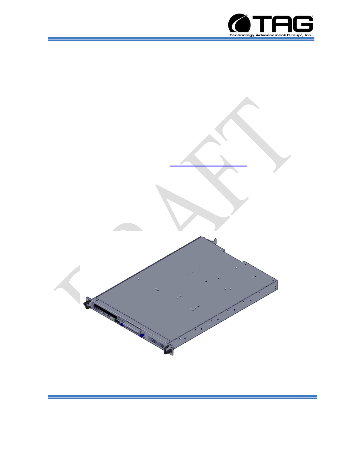
5.1.1 SV-1002-X2 Server
Figure 5-1 SV-1002-X2 P/N 1008826, P/N 1008871 Server
Document Number: 282-MNL-009 P/N1008826, 1009006, 1008871 Page 14 of 44
SV-1002-X2 Server
Version A. 10/25/2010
Page 15

Operations Manual
5.1.2 SV-1002-X2 Server
Figure 5-2 SV-1002-X2 P/N 1009006 Server
5.1.3 Specifications
Chassis & power supply:
1U Heavy-duty aluminum rack-mount chassis.
Chassis is designed to EIA-310-D Standards.
1.719”H (1U) x 16.88”W x 24.070”D.
Cooling system developed specifically for
harsh environments.
Front accessible on/off switches.
Processor & Cache:
Single Intel Quad Core Xeon Processor L5618
(1.87GHz,12MB Cache, 5.86 GT/s Intel QPI).
I/O
External connections:
DB-15 Video connector
RJ-45 serial Port A connector
Two RJ-45 Network Interface Connectors for
10/100/1000 Mb
Document Number: 282-MNL-009 P/N1008826, 1009006, 1008871 Page 15 of 44
Four USB 2.0 connectors
Internal connections:
One USB 2x5 pin header, supporting two USB
2.0 ports
SV-1002-X2 Server
Version A. 10/25/2010
Page 16

Operations Manual
One low-profile USB 2x5 pin header to support
low-profile USB solid state drives
One DH-10 Serial Port B header
One SSI-EEB compliant front panel header
One SSI-EEB compliant 24-pin main power
connector
One SSI-compliant 8-pin CPU power connector
One SSI-compliant power supply SMBus
connector.
P/N 1008826 System Components:
12GB ECC DDR3 RAM (3x4GB modules)
Single 300GB removable SAS hard drive with
rugged metal carrier & receiver
Matrox XTOA-FESLPAF PCI-E Fibre interface
card (interface to Matrox remote graphics unitsupplied and warranted by TRS)
Slim- line SATA DVD-RW/CD-RW drive
24” 1U Slides
P/N 1008871 System Components:
12GB ECC DDR3 RAM (3x4GB modules)
Single 300GB removable SAS hard drive with
rugged metal carrier & receiver
Slim- line SATA DVD-RW/CD-RW drive
24” 1U Slides
P/N 1009006 System Components:
24GB ECC DDR3 RAM (6x4GB modules)
Dual 300GB Hot Swap removable SAS hard
drives with rugged metal carrier & receivers
(configured in a RAID 1)
Slim- line SATA DVD-RW/CD-RW drive
Q-Logic (P/N-QLE 2562-CK) PCI-Express Dual
Port Fibre Channel; HBA
24” 1U Slides
Document Number: 282-MNL-009 P/N1008826, 1009006, 1008871 Page 16 of 44
SV-1002-X2 Server
Version A. 10/25/2010
Page 17

Operations Manual
Normal Output
Voltage
Load Current (A)
Min Max
Regulation Tolerance
Max Min
+5V
0.5A 25A
+5% -5%
+12V
2A 40A
+5% -5%
-12V
0A 0.8A
+5% -5%
+3.5V
0.5A 25A
+5% -5%
+5V sb
0.1A 3.5A
+5% -5%
5.1.4 Additional specifications
Power Input
Input voltage range is 100V to 240V range
(With + - 10% tolerance).
Input frequency range is 60hz nominal but can
go from 47 ~ 63 to hertz.
Steady-State Current 8A/4A at any low/high
range input voltage.
Power supply max available power is 550
watts.
Inrush current at 20/40Amps @ 115/230 VAC.
Inrush current at 230VAC is 4 amps max
Power Factor Correction can reach the target
of 95% @ 115/230VAC, Full Load.
Power Output
Table 5-1 Power Output.
SV-1002-X2 Server
Document Number: 282-MNL-009 P/N1008826, 1009006, 1008871 Page 17 of 44
Version A. 10/25/2010
Page 18
Operations Manual
5.1.5 Server Highlights
The SV-1002-X2 Server is unlike any other
Server that is currently on the market. The SV1002-X2 Server is ideal for use in deployable
situations where the product’s compact size,
high density computing, minimized size,
weight, and power make for a highly portable,
rugged and reliable system.
Contains an intelligent fan controller
(acoustically optimized, environmentally
aware).
Small-form factor chassis.
Proven to function in a variety of operating
temperature ranges from 0C TO 50C.
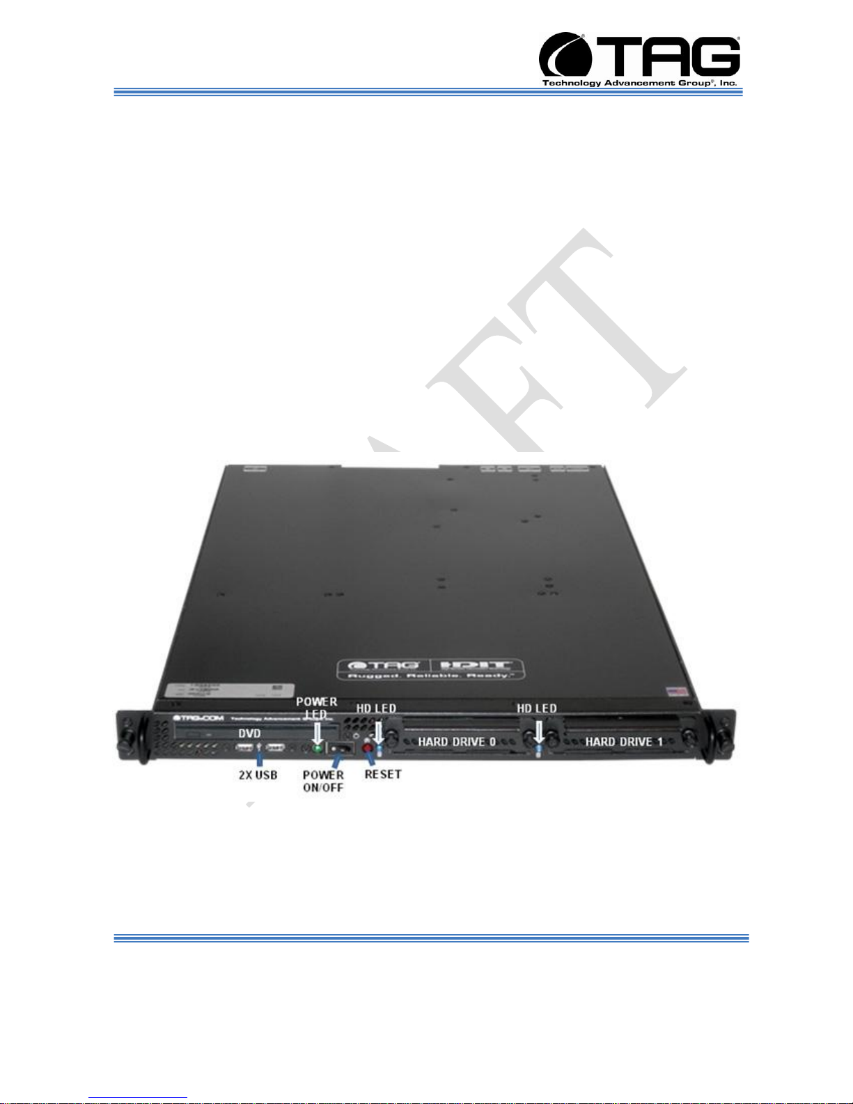
5.1.6 SV-1002-X2 Server
Figure 5-3 SV-1002-X2 P/N 1009006 Server Components and Connectors. (Front
Document Number: 282-MNL-009 P/N1008826, 1009006, 1008871 Page 18 of 44
View).
SV-1002-X2 Server
Version A. 10/25/2010
Page 19

Operations Manual
Figure 5-4 SV-1002-X2 P/N 1008826, P/N 1008871 Server Components and
Connectors. (Front View).
Figure 5-5 SV-1002-X2 P/N 1008826 Server I/O Connectors (Rear View).
Document Number: 282-MNL-009 P/N1008826, 1009006, 1008871 Page 19 of 44
SV-1002-X2 Server
Version A. 10/25/2010
Page 20

Operations Manual
Figure 5-6 SV-1002-X2 P/N 1009006 Server I/O Connectors (Rear View).
Figure 5-7 SV-1002-X2 P/N 1008871 Server I/O Connectors (Rear View).
Document Number: 282-MNL-009 P/N1008826, 1009006, 1008871 Page 20 of 44
SV-1002-X2 Server
Version A. 10/25/2010
Page 21

Operations Manual
5.1.7 Server Components
This section provides an overview of the most
common components installed in the SV-1002X2 Server. Information is also provided on how
to identify specific components within your
Server. For detailed information on specific
components installed in your Server, TAG
Technical Support at: tech.support@tag.com.
5.1.7.1 SV-1002-X2 S5520UR Server Board
Figure 5-8 SV-1002-X2 S5520UR Server Board
Document Number: 282-MNL-009 P/N1008826, 1009006, 1008871 Page 21 of 44
SV-1002-X2 Server
Version A. 10/25/2010
Page 22

Operations Manual
5.1.7.2 Server Board Connector and Component Layout
Figure 5-7 shows the board layout of the server
board. Each connector and major component
is identified by a number or letter, a description
is given in Table 5-2.
Figure 5-9 Server Board S5520UR Layout.
Document Number: 282-MNL-009 P/N1008826, 1009006, 1008871 Page 22 of 44
SV-1002-X2 Server
Version A. 10/25/2010
Page 23

Operations Manual
Feature
Description
Processors
Support
One or two Intel® Xeon® Processor 5500 Series with a 4.8
GT/s, 5.86 GT/s, or 6.4 GT/s Intel® QPI link interface and Thermal
Design Power (TDP) up to 95 W.
One or two Intel® Xeon® Processor 5600 Series with a 6.4
GT/s Intel® QPI link interface and Thermal Design Power (TDP) up
to 130 W.
Enterprise Voltage Regulator-Down (EVRD) 11.1
Memory
Support for 800/1066/1333 MT/s ECC registered (RDIMM) or
unbuffered (UDIMM) DDR3 memory.
12 DIMMs total across 6 memory channels (3 channels per
processor).
Chipset
Intel® 5520 Chipset IOH
Intel® 82801Jx I/O Controller Hub (ICH10R)
I/O Control
External connections:
DB-15 Video connector
RJ-45 serial Port A connector
Two RJ-45 Network Interface Connectors for 10/100/1000 Mb
Four USB 2.0 connectors
Internal connections:
One USB 2x5 pin header, supporting two USB 2.0 ports
One low-profile USB 2x5 pin header to support low-profile
USB solid state drives
One DH-10 Serial Port B header
Six SATA II connectors
Two I/O module Mezzanine connectors for optional I/O
Module support
emote
Management Module 3
SATA SW RAID 5 Activation Key Connector
One SSI-EEB compliant front panel header
One SSI-EEB compliant 24-pin main power connector
One SSI-compliant 8-pin CPU power connector
One SSI-compliant power supply SMBus connector
System Fan
Support
Six 4-pin fan headers supporting 2 processor fans, 2 memory fans,
and up to 2 system fans
One 26-pin custom system fan header for use in an Intel® Server
Chassis
Feature
Description
5.1.7.3 Server Board S5520UR Components
Document Number: 282-MNL-009 P/N1008826, 1009006, 1008871 Page 23 of 44
SV-1002-X2 Server
Version A. 10/25/2010
Page 24

Operations Manual
Add-in Adapter
Support
One riser slot supporting both full-height and low-profile 1U and 2U
PCI Express* riser cards
Video
On-board ServerEngines* LLC Pilot II Controller
Integrated 2D Video Controller
32 MB DDR2 Memory
Hard Drive
Support for six ICH10R SATA II ports
Intel® Matrix RAID Technology with Software RAID levels 0/1/10
Optional support for Software RAID 5 with activation key
LAN
Two 10/100/1000 ports provided by Intel® 82575 PHYs
Security**
Trusted Platform Module
Server
Management
On-board ServerEngines* LLC Pilot II Controller
Integrated Baseboard Management Controller (Integrated
BMC), IPMI 2.0 compliant
Integrated Super I/O on LPC interface
Support for Intel® Server Management Software 3.1
Table 5-2 Server Board Components
SV-1002-X2 Server
Document Number: 282-MNL-009 P/N1008826, 1009006, 1008871 Page 24 of 44
Version A. 10/25/2010
Page 25

Operations Manual
5.1.8 SV-1002-X2 Server Integrated Server RAID Module
For 1U and 2U servers, the unique module
shape and specialized PCI Express*
connector provide the ability to easily
implement a robust RAID solution in
popular 1U and 2U form factor systems,
without sacrificing a valuable risercard
slot or using a chassis with low-profile add-in
card cut-outs...
5.1.8.1 Integrated Server RAID Module
Figure 5-10 Integrated Server RAID Module
5.1.8.2 RAID Module Specifications
RAID Levels
Option 1: Entry Hardware RAID 0, 1, and 1E
Option 2: Software RAID 0, 1, 10
Option 3: Software RAID 5 (requires optional
AXXRAKSW5)
Option 4: Pass-through SAS
Fault Tolerance Features
Distributed Sparing
SV-1002-X2 Server
Document Number: 282-MNL-009 P/N1008826, 1009006, 1008871 Page 25 of 44
Version A. 10/25/2010
Page 26

Operations Manual
Hot Spare Support
Expander Support
Enclosure Management
S.M.A.R.T. Support
RAID support before operating system loaded
Intel® RAID Software
Intel® Embedded RAID II Configuration Utility
Intel® RAID Web Console 2
Intel® SAS Flash
I/O Processor
LSISAS1064E
Drive Types
SAS or SATA 3Gb/s
Maximum Drives
Up to 122 physical devices supported with SAS
mode and up to 14 devices with RAID
0/1/1E/10E
Tape drives supported as a pass-through
devices in RAID modes
Connectors
Four SATA x1 SAS internal connectors
PCI Interface
PCI Express* x4
Form Factor
Custom 1U capable for server boards with the
appropriate module connector
Data Transfer Rates
Up to 3 GB/s per port
Operating Temperature
Maximum ambient: 60°C
Operating Voltage.
+3.3V
Document Number: 282-MNL-009 P/N1008826, 1009006, 1008871 Page 26 of 44
SV-1002-X2 Server
Version A. 10/25/2010
Page 27

Operations Manual
5.1.9 Q-Logic PCI-Express Dual Port Fibre Channel HBA
QLE2562 Host Bus Adapter. The QLE2562 is a
PCI Express, dual port, Fibre Channel (FC)
Host Bus Adapter (HBA).
Figure 5-11 Q-Logic PCI-Express Dual Port Fibre Channel HBA (SV-1002-X2
P/N 1009006).
Features
Virtualization optimized
Power optimized
Reliability, Availability, Serviceability (RAS)
optimized
Security optimized
Management optimized
Fibre Channel 8Gb to PCI Express x8
3200 MBps (full-duplex)
200,000 initiator and target IOPS per port
StarPower™ technology
Document Number: 282-MNL-009 P/N1008826, 1009006, 1008871 Page 27 of 44
SV-1002-X2 Server
Version A. 10/25/2010
Page 28
Operations Manual
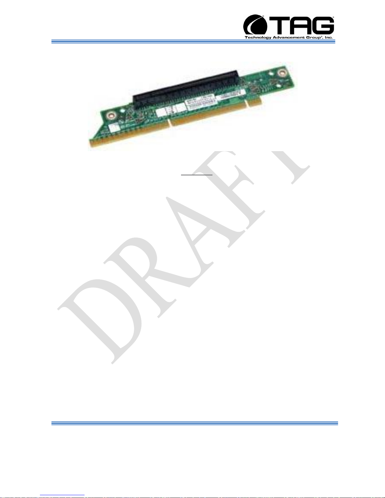
5.1.10 Riser Card
Figure 5-12 1U PCIeX16 Riser Card
Features
1 Slot PCI-e Passive Riser.
1 full-size x16 physical x16 electrical slot.
Document Number: 282-MNL-009 P/N1008826, 1009006, 1008871 Page 28 of 44
SV-1002-X2 Server
Version A. 10/25/2010
Page 29

Operations Manual
5.1.11 Matrox XTOA-FESLPAF PCIe Fiber Interface card
The interface card installed in the server
converts outgoing bus data to an optical signal
and converts incoming bus data back to an
electrical signal. The card transmits and
receives this optical data to and from the
remote graphics unit via fiber-optic cable. Extio
has integrated graphics, audia, and USB
hardware that process the bus data as if it
were part of an add-in card directly installed in
a server expansion slot.
Figure 5-13 PCIe Interface Card. (SV-1002-X2 P/N 1008826)
5.1.12 Specifications
Document Number: 282-MNL-009 P/N1008826, 1009006, 1008871 Page 29 of 44
Bus Type: PCI Express x 1 (works in PCIe x1,
x4 and x16
Dimensions: 2.7" x 2.7"
SV-1002-X2 Server
Version A. 10/25/2010
Page 30
Operations Manual
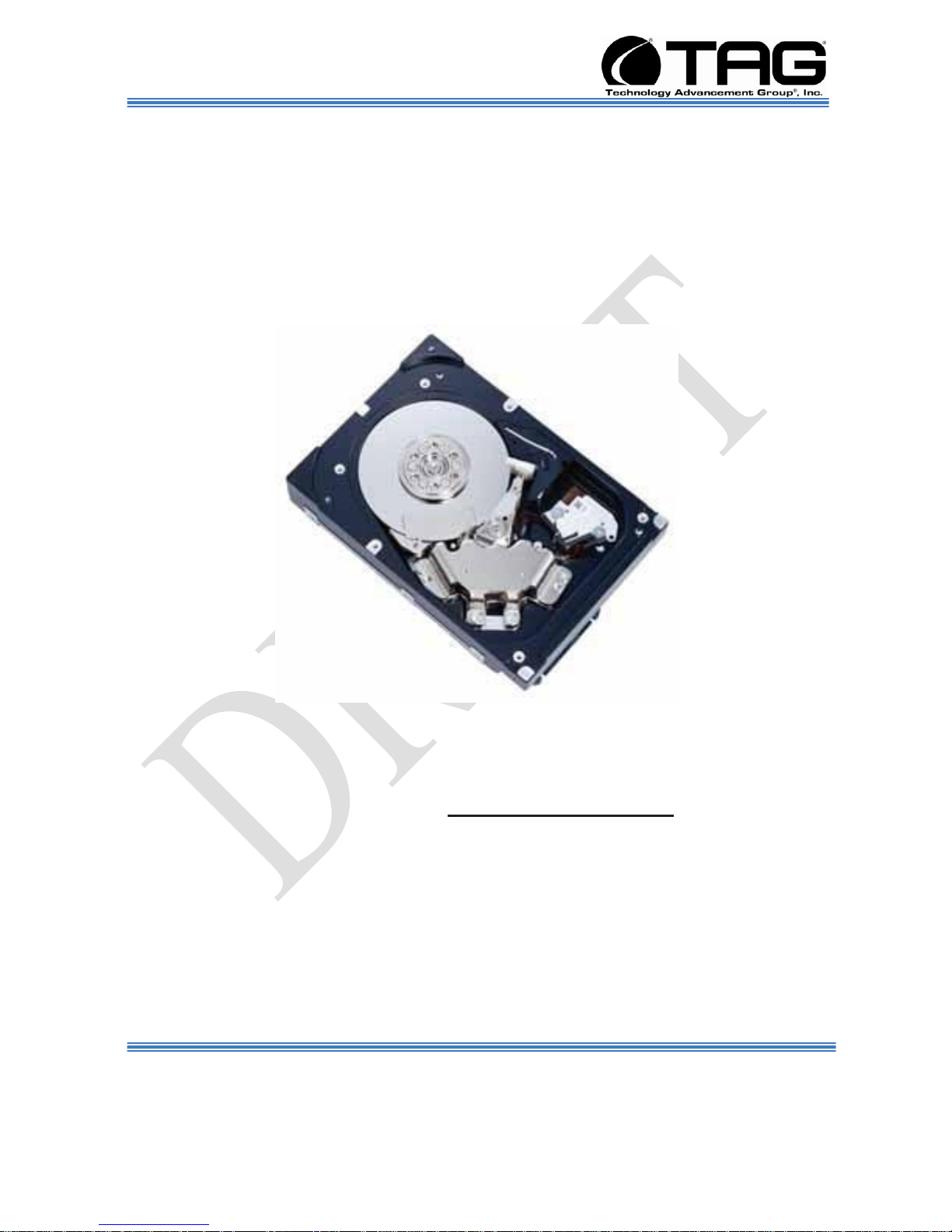
5.1.13 3.5” Hard Drive
3.5-inch 15K RPM ENTERprise hard
disk drive features a host of innovations. The
300GB, 4-platter configuration provides low
power consumption, high reliability, and faster
internal data rates. Interface options include
3Gb/sec SAS, 68/80-pin U320 SCSI and
4Gb/sec Fibre Channel.
Figure 5-14 3.5” Hard Drive
5.1.13.1 3.5”, SAS, Hard Drive
Functional Specifications
Storage capacity (formatted)1 300.0 GB
Disks 1 2 4
Heads (read/write) 2 4 8
Bytes/sector 512.
Seek time Track to track Read: 0.2 ms (typ.) /
Write: 0.4 ms (typ.)
Average Read: 3.4 ms (typ) / Write: 3.9 ms
(typ)
SV-1002-X2 Server
Document Number: 282-MNL-009 P/N1008826, 1009006, 1008871 Page 30 of 44
Version A. 10/25/2010
Page 31

Operations Manual
Full track Read: 8.0 ms (typ) / Write: 9.0 ms
(typ)
Average latency time 2.00 ms
Rotational speed (RPM) 15,000
Areal density 112.8 Gbits/sq. in.
Data transfer To/from media 179MB/sec rate
To/from host SAS: 3Gb/sec, SCSI: 320MB/sec,
FCAL: 4Gb/sec
Recording code 60/62 MEEPRML
Interface Dual Port SAS (RC Series), SCA-2
80Pin (NC Series), 68Pin Wide (NP Series),
Dual Port FCAL (FC series)
Head positioning method Rotary VCM
Start time 30 s (typ)
Stop time 30 s (typ)
Buffer size SCSI 8 MB
SAS, FC 16 MB
Physical Specifications
Power Voltage 5 V ± 5%, 12 V ± 5%
requirements Spin-up 12 V ± 5% @ 2.5 A
(peak)
A (peak < 100 us)
5 V ± 5% @ 0.8 A
Idle (typ.) SAS 12.8 W
SCSI 12.4 W
FC 13.4 W
Dimensions (HxWxD) 25.4 mm x 101.6 mm x
146.0 mm
Weight 800 g
Ambient Operating 5°C to 55°C (HDD surface
60°C max) temperature Non-operating -40°C to
70°C
Gradient 20°C/Hour (max)
Relative Operating 5% to 95% (non-
condensing)
humidity Non-operating 5% to 95% (non-
condensing)
Max. wet bulb 29°C (operating)
Vibration Operating 0.6 mm (5 to 20 Hz) / 1.0
G (20 to 300 Hz)
Document Number: 282-MNL-009 P/N1008826, 1009006, 1008871 Page 31 of 44
SV-1002-X2 Server
Version A. 10/25/2010
Page 32

Operations Manual
Non-operating 3.1 mm (5 to 20 Hz) / 5.0 G (20
to 300 Hz)
Shock Operating 65 G max. (2 ms)
Non-operating 250 G max. (2 ms)
Altitude Operating 3,048 m (max.) (operation)
Non-operating 12,192 m (max.)
Acoustic Noise (idle sound power) (typ.) </=
3.6 bels (idle)
Reliability Specifications
Mean time between failures (MTBF) 1,400,000
hours
Error rates Unrecoverable errors 1 per 1015
bits read
Seek errors 10 per 108 seeks
Document Number: 282-MNL-009 P/N1008826, 1009006, 1008871 Page 32 of 44
SV-1002-X2 Server
Version A. 10/25/2010
Page 33

Operations Manual
Chapter 3
Procedures.
Electronically distributed. Subject to user discretion when printed.
Document Number: 282-MNL-009 P/N1008826, 1009006, 1008871 Page 33 of 44
SV-1002-X2 Server
Version A. 10/25/2010
Page 34

Operations Manual
6 Procedures
The procedures within this Chapter contain
relevant information to ensure your SV-1002X2 Server maintains its maximum performance
potential.
6.1.1 Server Startup
1. Check to make sure that all the cables are
seated and connected correctly to the back of
the unit such as keyboard, mouse, monitor
video and power cables.
2. Then Press the power switch ON to start the
server (power switch is located in the front of
the unit). (Figure 5.2).
3. Once the unit starts, System will go thru Power
On self Test (POST) (no action is required at
this time).
6.1.2 Server Shutdown
1. Press the Power ON/OFF Switch.
Document Number: 282-MNL-009 P/N1008826, 1009006, 1008871 Page 34 of 44
SV-1002-X2 Server
Version A. 10/25/2010
Page 35

Operations Manual
6.1.3 Upgrading and Replacing System Components
6.1.3.1 Preventing Static Electricity
This section provides procedures for replacing
all hot-swappable and LRU components,
including procedures for replacing or adding
system memory.
The components inside your server are
extremely sensitive to static electricity, also
known as electrostatic discharge (ESD). ESD
can permanently damage electrostatic
discharge-sensitive components in your
Server.
To prevent ESD damage, follow these
guidelines before opening the Server case:
1. Turn off the Server and unplug the power
cord before opening the case.
2. Wear a grounding wrist strap and attach it to
a bare metal part of the Server, workbench, or
other grounded connection.
Figure 6-1 Grounding Wrist Strap
3. Do not insert any object into the vent holes on
the case or the power supply. Touch a bare
metal surface on the back of the server, a bare
metal surface on your workbench, or other
grounded object before handing DIMMs or
other components.
Document Number: 282-MNL-009 P/N1008826, 1009006, 1008871 Page 35 of 44
SV-1002-X2 Server
Version A. 10/25/2010
Page 36

____1.0 :Initial Check Points
____1.1
VERIFY the Work Permit
instructions have been completed.
Operations Manual
Before working with server components,
follow these guidelines:
1. Avoid static-causing surfaces such as carpeted
floors, plastic, and packing foam.
2. Remove components from their antistatic bags
only when you are ready to use them. Do not
lay components on the outside of antistatic
bags because only the inside of the bags
provide electrostatic protection. Always hold
memory modules and components by their
edges or their metal mounting brackets.
3. Avoid touching the edge connectors and
components on the cards. Never slide memory
modules or components over any surface.
6.1.3.2 Removing the Server Cover
The location of the mounting screws securing
the Server cover varies per Server model. To
remove the cover, use a Phillips screwdriver to
remove all screws from the sides and top of the
cover.
NOTE: It is important to make note of the
location from which screws are removed
since different screw lengths may be used
to secure the cover.
CAUTION
It is not safe to operate TAG Servers
without the cover in place. Failure to take
this precaution may result in personal
injury and system damage.
6.1.4 Power Supply Cable Retention Bracket Installation
Document Number: 282-MNL-009 P/N1008826, 1009006, 1008871 Page 36 of 44
SV-1002-X2 Server
Version A. 10/25/2010
Page 37

____1.2
VERIFY locks and tags are properly
attached to equipment.
____1.3
VERIFY all power is removed from
the Server.
____2.0 Install AC Retainer
Bracket:
____2.1
SV-1002-X2 SERVER-Server.
(Figure 7.10).
Figure 6-2 SV-1002-X2 Server(Rear View)
____2.3
Power Supply Cable Retention
Bracket. (Figure 7.11).
Figure 6-3 Power Supply Cable Retention Bracket.
____2.4
Secure Power Supply Cable
Retention Bracket by the Two
supplied screws. (Figure 7.12).
Figure 6-4 Secure Power Supply Cable Retention Bracket.
Operations Manual
Document Number: 282-MNL-009 P/N1008826, 1009006, 1008871 Page 37 of 44
SV-1002-X2 Server
Version A. 10/25/2010
Page 38

Operations Manual
6.1.5 Replacing a Hard Drive
To remove the systems Hard Drive you need to
stop the hard drive and take it offline to remove
the logical software links to the hard drive, and
to reconfigure the file system so that it will
recognize the new drive. You will have to
reconfigure your application software.
Therefore it is strongly recommended that you
contact TAG Technical Support at
tech.support@tag.com before attempting to
exchange the hard drive. For more information
on contact information see Manual back page.
6.1.5.1 3.5” SAS Hard Drive
Figure 6-5 3.5 SAS Hard Drive.
6.1.6 Adding or Replacing System Memory
This section lists the procedures for adding or
replacing system memory.
WARNING
Ensure that the system is powered-down
and all power sources have been
disconnected from the Server prior to
removing or replacing system memory.
Failure to do so could result in serious
injury from electrical shock.
SV-1002-X2 Server
Document Number: 282-MNL-009 P/N1008826, 1009006, 1008871 Page 38 of 44
Version A. 10/25/2010
Page 39

Operations Manual
CAUTION
Printed circuit boards and hard drives
contain electronic components that are
extremely sensitive to static electricity.
Ordinary amounts of static from your
clothes or the work environment can
destroy components. Do not touch the
components or any metal parts without
taking proper antistatic precautions.
6.1.7 Install System Memory.
Unlatch both DIMM socket levers, as shown in Figure 6-
33.
Figure 6-6 DIMM Module Bank
1. Note the location of the alignment notch.
2. Align the notches on the new module with the
notches on the memory and press it firmly into
the bank.
NOTE: The tabs on the sides of the memory
module should secure the DIMM
automatically. When the DIMM locks into
place, you will hear a click.
Document Number: 282-MNL-009 P/N1008826, 1009006, 1008871 Page 39 of 44
SV-1002-X2 Server
Version A. 10/25/2010
Page 40

PROBLEM
POSSIBLE SOLUTION
DVD/CD-ROM:.
Won’t Eject
Does unit have power?
Enabled in CMOS?
Correct IDE cable?
Won’t Read Disc
Reseat cable
Try disc in a good known DVD/CD-ROM Drive
Verify that you have correct IDE cable for the M/B
DVD/CD-Rom Drive not being recognized in CMOS
Reseat IDE and power cable
Verify that you have the correct IDE cable for the M/B
Enable drive in CMOS
Led blinking all the time (defective drive)
Hard Drive
Post Can Not Find The Hard Drives
Check CMOS & verify that the drive is recognized
If the drive is not spinning, check power cable for voltage
If the drive is spinning, check data cable for correct
connection.
If the drive is not still recognized by post, try
performing the following procedures in order:
Reconnect or swap the drive data cable
Exchange the hard drive with one you know is in good
working condition.
If the known good hard drive does not work, then suspect
the system board
If the problem is solved by exchange one of the above
modules, try re-installing the old module to verify that the
problem was not caused by a bad connection.
No Power Supply.
Good power source?
Can you hear fans turning and drives motor spinning
up?
Operations Manual
6.1.8 Troubleshooting
Document Number: 282-MNL-009 P/N1008826, 1009006, 1008871 Page 40 of 44
SV-1002-X2 Server
Version A. 10/25/2010
Page 41

Hear any beeps?
See green light on mother board
Check the 20/24 pin ATX power connector for loose pins
If the previous checks failed replace power supply.
Operations Manual
Table 6-1Trouble Shooting Guide
SV-1002-X2 Server
Document Number: 282-MNL-009 P/N1008826, 1009006, 1008871 Page 41 of 44
Version A. 10/25/2010
Page 42

Operations Manual
Appendix A
Document Number: 282-MNL-009 P/N1008826, 1009006, 1008871 Page 42 of 44
SV-1002-X2 Server
Version A. 10/25/2010
Page 43

Operations Manual
SV-1002-X2 Server
Document Number: 282-MNL-009 P/N1008826, 1009006, 1008871 Page 43 of 44
Version A. 10/25/2010
7 Contract Drawing SV-1002-X2 SERVER
Figure 7-1 Contract Drawing SV-1002-X2 Server
NOTE: This Contract Drawing is subject to change. Contact TAG for latest drawing Tel: 1-800-824-7693
www.tag.com
Page 44

Contact Information
7.1.1
22355 TAG Way
Dulles, VA 20166
Tel: 1-800-824-7693
www.tag.com
Technical Support
USA 1-800-824-7693
Outside USA
While every precaution has been taken
to ensure the accuracy and completeness
of this literature. TAG assumes
no responsibility and disclaims and liability
for damage resulting from use of this information
or for any errors or omissions.
 Loading...