

Page 1
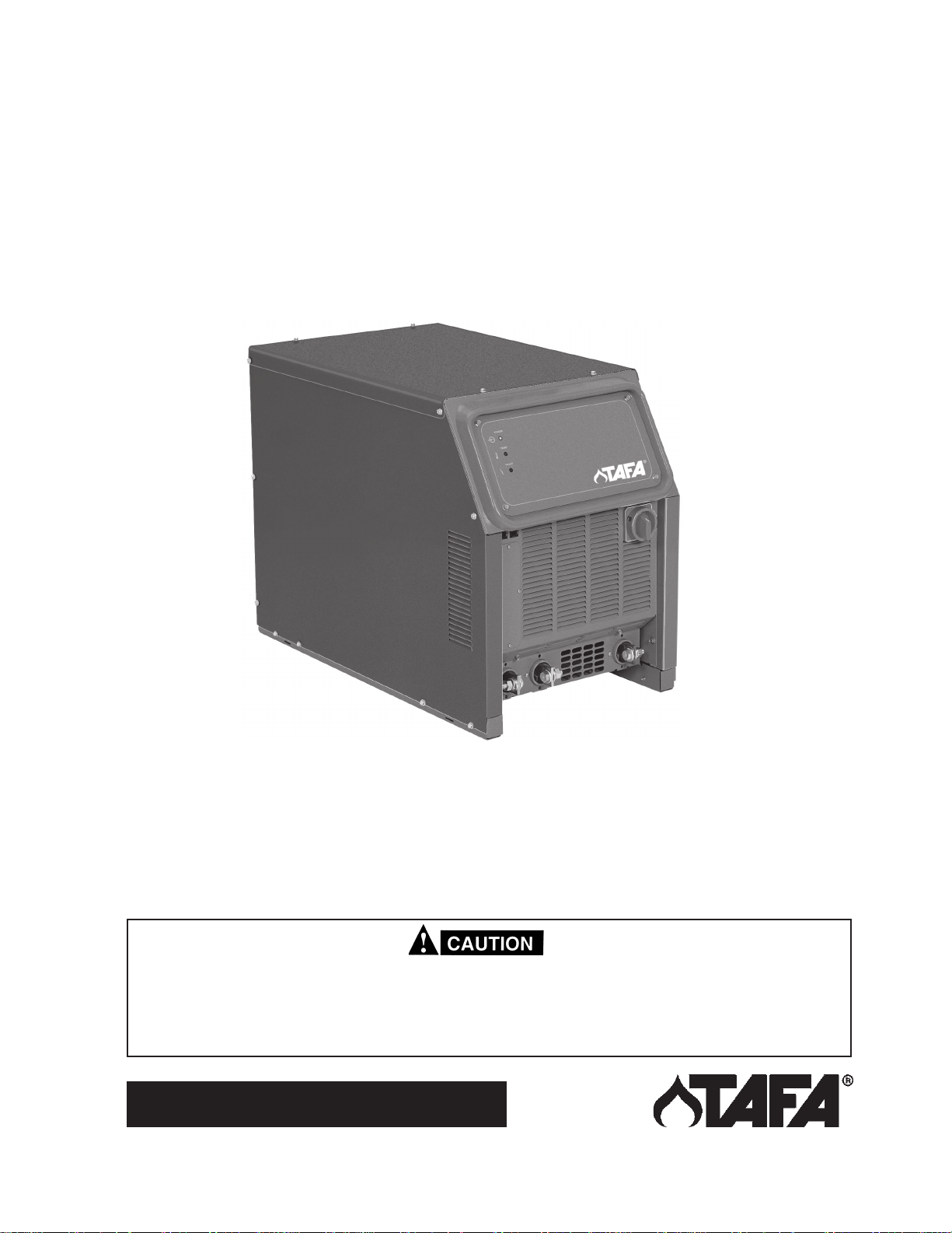
INSTRUCTION MANUAL
653CV
DC WELDING POWER SOURCE
F15-598-A
May, 2003
This manual provides complete instructions for the following power sources starting with Serial No. MB-I937011, September
1999:
653cv Power Source, 230/460 Vac, 60 Hz, P/N 37920
653cv Power Source, 230/460/575 Vac, 60 Hz, P/N 37921
653cv Power Source, 220/400 Vac, 50 Hz, P/N 37922, CE
These INSTRUCTIONS are for experienced operators. If you are not fully familiar with the principles of operation
and safe practices for arc welding equipment, we urge you to read our booklet, "Precautions and Safe Practices
for Arc Welding, Cutting, and Gouging," Form 52-529. Do NOT permit untrained persons to install, operate, or
maintain this equipment. Do NOT attempt to install or operate this equipment until you have read and fully
understand these instructions. If you do not fully understand these instructions, contact your supplier for
further information. Be sure to read the Safety Precautions before installing or operating this equipment.
Be sure this information reaches the operator.
You can get extra copies through your supplier.
Page 2

USER RESPONSIBILITY
This equipment will perform in conformity with the description thereof contained in this manual and accompanying labels and/or
inserts when installed, operated, maintained and repaired in accordance with the instructions provided. This equipment must be
checked periodically. Malfunctioning or poorly maintained equipment should not be used. Parts that are broken, missing, worn,
distorted or contaminated should be replaced immediately. Should such repair or replacement become necessary, the
manufacturer recommends that a telephone or written request for service advice be made to the Authorized Distributor from whom
purchased.
This equipment or any of its parts should not be altered without the prior written approval of the manufacturer. The user of this
equipment shall have the sole responsibility for any malfunction which results from improper use, faulty maintenance, damage,
improper repair or alteration by anyone other than the manufacturer or a service facility designated by the manufacturer.
TABLE OF CONTENTS
SECTION TITLE PAGE
PARAGRAPH
SAFETY SAFETY PRECAUTIONS .................................................................................................................. 3
SECTION 1 DESCRIPTION ................................................................................................................................... 7
1.1 General ............................................................................................................................................... 7
1.2 Receiving-Handling ............................................................................................................................ 7
1.3 Description.......................................................................................................................................... 7
1.3.1 Power Source ..................................................................................................................................... 7
1.3.2 Volt-Ampere Characteristics............................................................................................................... 7
1.4 Optional Accessories.......................................................................................................................... 8
1.4.1 TR-29 Truck Kit .................................................................................................................................. 8
1.4.2 Swivel Mount Kit ................................................................................................................................. 8
1.4.3 Automatic Fan Kit ............................................................................................................................... 8
1.5 Safety ................................................................................................................................................. 8
SECTION 2 INSTALLATION ................................................................................................................................. 9
2.1 Location .............................................................................................................................................. 9
2.2 Receiving, Unpacking and Placement ............................................................................................... 9
2.3 Primary (Input) Electrical Connection ................................................................................................ 9
2.4 Secondary (Output) Welding Connections......................................................................................... 11
2.5 Control Connections........................................................................................................................... 11
2.5.1 Remote Control (Optional) ................................................................................................................. 11
2.5.2 Auxiliary 115 V ac Receptacle ........................................................................................................... 11
2.5.3 42 V Circuit Breaker ........................................................................................................................... 11
2.5.4 115 V Circuit Breaker ......................................................................................................................... 11
2.5.5 External Grounding Conductor Protection Kit .................................................................................... 11
SECTION 3 OPERATION ...................................................................................................................................... 13
3.1 Controls .............................................................................................................................................. 13
3.1.1 Power Switch (ON-OFF)/(I-O) ............................................................................................................ 13
3.1.1.1 Power Indicator .................................................................................................................................. 13
3.1.1.2 Over Temperature Indicator (Temp). ................................................................................................. 13
3.1.1.3 Fault Indicator ..................................................................................................................................... 13
3.1.6 Over Current Protection ..................................................................................................................... 13
3.1.7 High & Low Inductance Receptacles ................................................................................................. 13
SECTION 4 MAINTENANCE ................................................................................................................................. 14
4.1 General ............................................................................................................................................... 14
4.2 Cleaning ............................................................................................................................................. 14
4.3 Inspection and Service ....................................................................................................................... 14
4.3.1 Fan Motor ........................................................................................................................................... 14
4.3.2 Transformer ........................................................................................................................................ 14
4.3.3 Wire Feeder and Control Circuits....................................................................................................... 14
4.3.4 Over Temperature Protection............................................................................................................. 14
4.3.5 Digital Voltmeter/Ammeter Calibration............................................................................................... 14
SECTION 5 TROUBLESHOOTING ....................................................................................................................... 15
5.1 General ............................................................................................................................................... 15
5.2 Testing and Replacing Bridge Assembly Components...................................................................... 15
SECTION 6 REPLACEMENT PARTS................................................................................................................... 17
6.1 General ............................................................................................................................................... 17
Parts Diagrams & List......................................................................................................................... 18
2
Page 3
SAFETY PRECAUTIONS
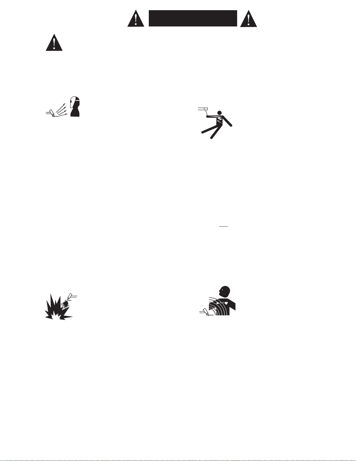
WARNING: These Safety Precautions are for
your protection. They summarize precautionary information from the references listed in
Additional Safety Information section. Before
performing any installation or operating procedures, be
sure to read and follow the safety precautions listed below
as well as all other manuals, material safety data sheets,
labels, etc. Failure to observe Safety Precautions can result
in injury or death.
PROTECT YOURSELF AND OTHERS
Some welding, cutting, and gouging
processes are noisy and require ear
protection. The arc, like the sun, emits
ultraviolet (UV) and other radiation and
can injure skin and eyes. Hot metal can cause burns.
Training in the proper use of the processes and equipment is essential to prevent accidents. Therefore:
1. Always wear safety glasses with side shields in any work
area, even if welding helmets, face shields, and goggles
are also required.
2. Use a face shield fitted with the correct filter and cover
plates to protect your eyes, face, neck, and ears from
sparks and rays of the arc when operating or observing
operations. Warn bystanders not to watch the arc and
not to expose themselves to the rays of the electric-arc
or hot metal.
3. Wear flameproof gauntlet type gloves, heavy long-sleeve
shirt, cuffless trousers, high-topped shoes, and a welding helmet or cap for hair protection, to protect against
arc rays and hot sparks or hot metal. A flameproof apron
may also be desirable as protection against radiated
heat and sparks.
4. Hot sparks or metal can lodge in rolled up sleeves,
trouser cuffs, or pockets. Sleeves and collars should be
kept buttoned, and open pockets eliminated from the
front of clothing
5. Protect other personnel from arc rays and hot sparks
with a suitable non-flammable partition or curtains.
6. Use goggles over safety glasses when chipping slag or
grinding. Chipped slag may be hot and can fly far.
Bystanders should also wear goggles over safety glasses.
FIRES AND EXPLOSIONS -- Heat from
flames and arcs can start fires. Hot slag
or sparks can also cause fires and explosions. Therefore:
1. Remove all combustible materials well away from the
work area or cover the materials with a protective nonflammable covering. Combustible materials include wood,
cloth, sawdust, liquid and gas fuels, solvents, paints and
coatings, paper, etc.
2. Hot sparks or hot metal can fall through cracks or
crevices in floors or wall openings and cause a hidden
smoldering fire or fires on the floor below. Make certain
that such openings are protected from hot sparks and
metal.“
3. Do not weld, cut or perform other hot work until the
workpiece has been completely cleaned so that there
are no substances on the workpiece which might produce flammable or toxic vapors. Do not do hot work on
closed containers. They may explode.
4. Have fire extinguishing equipment handy for instant use,
such as a garden hose, water pail, sand bucket, or
portable fire extinguisher. Be sure you are trained in its
use.
5. Do not use equipment beyond its ratings. For example,
overloaded welding cable can overheat and create a fire
hazard.
6. After completing operations, inspect the work area to
make certain there are no hot sparks or hot metal which
could cause a later fire. Use fire watchers when necessary.
7. For additional information, refer to NFPA Standard 51B,
"Fire Prevention in Use of Cutting and Welding Pro-
--
cesses", available from the National Fire Protection Association, Batterymarch Park, Quincy, MA 02269.
ELECTRICAL SHOCK -- Contact with live
electrical parts and ground can cause
severe injury or death. DO NOT use AC
welding current in damp areas, if movement is confined, or if there is danger of
falling.
1. Be sure the power source frame (chassis) is connected
to the ground system of the input power.
2. Connect the workpiece to a good electrical ground.
3. Connect the work cable to the workpiece. A poor or
missing connection can expose you or others to a fatal
shock.
4. Use well-maintained equipment. Replace worn or damaged cables.
5. Keep everything dry, including clothing, work area, cables,
torch/electrode holder, and power source.
6. Make sure that all parts of your body are insulated from
work
and from ground.
7. Do not stand directly on metal or the earth while working
in tight quarters or a damp area; stand on dry boards or
an insulating platform and wear rubber-soled shoes.
8. Put on dry, hole-free gloves before turning on the power.
9. Turn off the power before removing your gloves.
10. Refer to ANSI/ASC Standard Z49.1 (listed on next page)
for specific grounding recommendations. Do not mistake
the work lead for a ground cable.
ELECTRIC AND MAGNETIC FIELDS —
May be dangerous. Electric current flowing through any conductor causes localized Electric and Magnetic Fields
(EMF). Welding and cutting current creates EMF around welding cables and
welding machines. Therefore:
1. Welders having pacemakers should consult their physician before welding. EMF may interfere with some pacemakers.
2. Exposure to EMF may have other health effects which are
unknown.
3. Welders should use the following procedures to minimize
exposure to EMF:
A. Route the electrode and work cables together. Secure
them with tape when possible.
B. Never coil the torch or work cable around your body.
C. Do not place your body between the torch and work
cables. Route cables on the same side of your body.
D. Connect the work cable to the workpiece as close as
possible to the area being welded.
E. Keep welding power source and cables as far away
from your body as possible.
3
TAFA - 10/98
Page 4
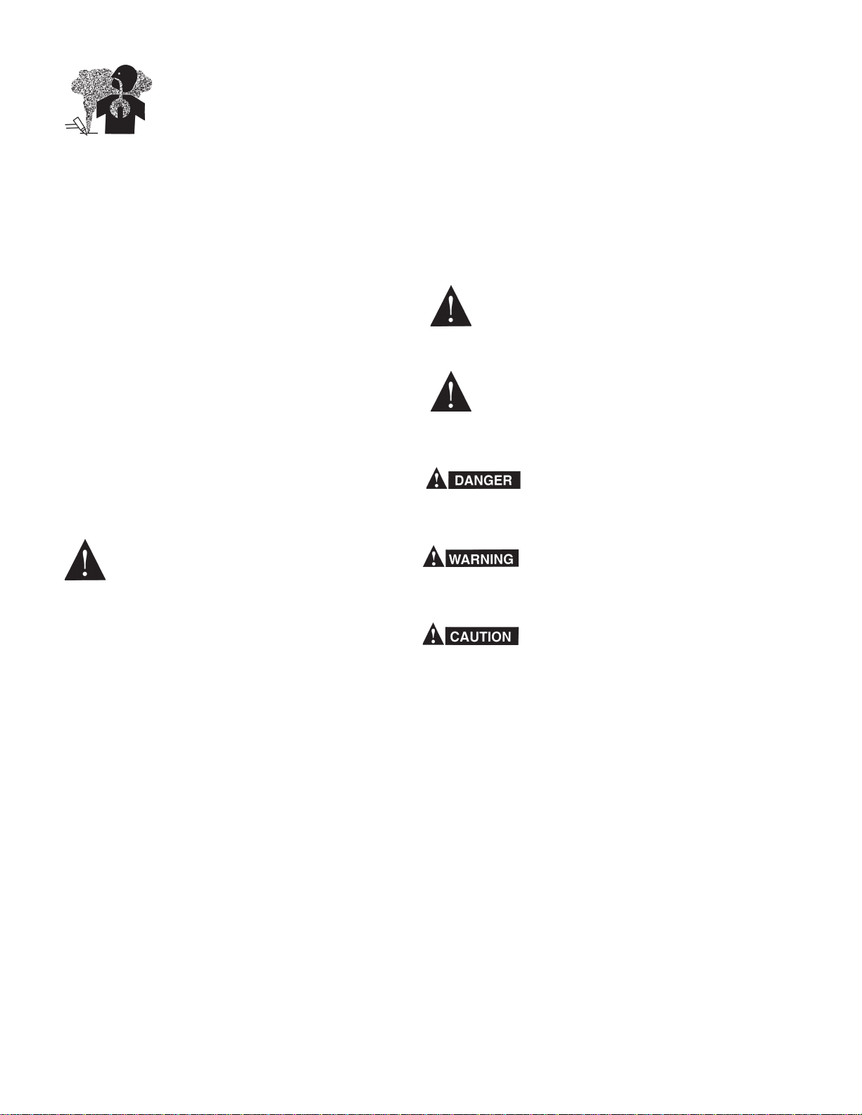
FUMES AND GASES -- Fumes and
gases, can cause discomfort or harm,
particularly in confined spaces. Do
not breathe fumes and gases. Shielding gases can cause asphyxiation.
Therefore:
1. Always provide adequate ventilation in the work area by
natural or mechanical means. Do not weld, cut, or gouge
on materials such as galvanized steel, stainless steel,
copper, zinc, lead, beryllium, or cadmium unless positive
mechanical ventilation is provided. Do not breathe fumes
from these materials.
2. Do not operate near degreasing and spraying operations. The heat or arc rays can react with chlorinated
hydrocarbon vapors to form phosgene, a highly toxic
gas, and other irritant gases.
3. If you develop momentary eye, nose, or throat irritation
while operating, this is an indication that ventilation is not
adequate. Stop work and take necessary steps to improve ventilation in the work area. Do not continue to
operate if physical discomfort persists.
4. Refer to ANSI/ASC Standard Z49.1 (see listing below)
for specific ventilation recommendations.
5. WARNING: This product, when used for welding or
cutting, produces fumes or gases which
contain chemicals known to the State of
California to cause birth defects and, in
some cases, cancer. (California Health &
Safety Code §25249.5 et seq.)
2. Before performing any maintenance work inside a power
source, disconnect the power source from the incoming
electrical power.
3. Maintain cables, grounding wire, connections, power
cord, and power supply in safe working order. Do not
operate any equipment in faulty condition.
4. Do not abuse any equipment or accessories. Keep
equipment away from heat sources such as furnaces,
wet conditions such as water puddles, oil or grease,
corrosive atmospheres and inclement weather.
5. Keep all safety devices and cabinet covers in position
and in good repair.
6. Use equipment only for its intended purpose. Do not
modify it in any manner.
ADDITIONAL SAFETY INFORMATION -- For
more information on safe practices for electric wire arc spraying, please refer to safety
section in owners manual.
MEANING OF SYMBOLS - As used throughout this manual: Means Attention! Be Alert!
Your safety is involved.
Means immediate hazards which, if
not avoided, will result in immediate,
serious personal injury or loss of life.
EQUIPMENT MAINTENANCE -- Faulty or
improperly maintained equipment can
cause injury or death. Therefore:
1. Always have qualified personnel perform the installation, troubleshooting, and maintenance work. Do not
perform any electrical work unless you are qualified to
perform such work.
Means potential hazards which could
result in personal injury or loss of life.
Means hazards which could result in
minor personal injury.
4
TAFA-10/98
Page 5

PRÉCAUTIONS DE SÉCURITÉ
AVERTISSEMENT: Ces règles de sécurité ont pour objet
d’ assurer votre protection. Veillez à lire et à observer les
précautions énoncées ci-dessous avant de monter l’
équipement ou de commercer à l’utiliser. Tout défaut
d’observation de ces précautions risque d’entraîner des
blessures graves ou mortelles.
1. PROTECTION INDIVIDUELLE-- Les brûlures de la
peau et des yeux dues au rayonnement de l’arc
électrique ou du métal incandescent, lors du soudage
au plasma ou à l’électrode ou lors du gougeage à
l’arc, peuvent s’avérer plus graves que celles
résultant d’une exposition prolongée au soleil. Aussi
convient-il d’observer les précautions suivantes:
a. Portez un écran facial adéquat muni des plaques
protectrices et des verres filtrants appropriés afin de
vous protéger les yeux, le visage, le cou et les oreilles
des étincelles et du rayonnement de l’arc électrique
lorsque vous effectuez des soudures ou des coupes
ou lorsque vous en observez l’exécution.
AVERTISSEZ les personnes se trouvant à proximité
de façon à ce qu’elles ne regardent pas l’arc et à ce
qu’elles ne s’exposent pas à son rayonnement, ni à
celui du métal incandescent.
b. Portez des gants ignifugés à crispins, une tunique
épaisse à manches longues, des pantalons sans
rebord, des chaussures à embout d’acier et un
casque de soudage ou une calotte de protection, afin
d’éviter d’exposer la peau au rayonnement de l’arc
électrique ou du métal incandescent. ll est également
souhaitable d’utiliser un tablier ininflammable de
façon à se protéger des étincelles et du rayonnement
thermique.
c. Les étincelles ou les projections de métal incandes-
cent risquent de se loger dans des manches
retroussées, des bords relevés de pantalons ou dans
des poches. Aussi convient-il de garder boutonnés le
col et les manches et de porter des vêtements sans
poches à l’avant.
d. Protégez des étincelles et du rayonnement de l’arc
électrique les autres personnes travaillant à proximité
à l’aide d’un écran ininflammable adéquat.
e. Ne jamais omettre de porter des lunettes de sécurité
lorsque vous vous trouvez dans un secteur où l’on
effectue des opérations de soudage ou de coupage à
l’arc. Utilisez des lunettes de sécurité à écrans ou
verres latéraux pour piquer ou meûler le laitier. Les
piquetures incandescentes de laitier peuvent être
projetées à des distances considérables. Les
personnes se trouvant à proximité doivent également
porter des lunettes de protection.
f. Le gougeage à l’arc et le soudage à l’arc au plasma
produisent un niveau de bruit extrêmement élevé (de
100 à 114 dB) et exigent par conséquent l’emploi de
dispositifs appropriés de protection auditive.
2. PRÉVENTION DES INCENDES-- Les projections de
laitier incandescent ou d’étincelles peuvent
provoquer de graves incendies au contact de
matériaux combustibles solides, liquides ou gazeux.
Aussi faut-il observer les précautions suivantes:
a. Éloigner suffisamment tous les matériaux combus-
tibles du secteur où l’on exécute des soudures ou des
coupes à l’arc, à moins de les recouvrir complètement
d’une bâche non-inflammable. Ce type de matériaux
comprend notamment le bois, les vêtements, la sciure,
l’essence, le kérosène, les peintures, les solvants, le
gaz naturel, l’acétylène, le propane et autres substances combustibles semblables.
b. Les étincelles ou les projections de métal incandes-
cent peuvent tomber dans des fissures du plancher ou
dans des ouvertures des murs et y déclencher une
ignition lente cachée. Veiller à protéger ces ouvertures
des étincelles et des projections de métal.
c. N’exécutez pas de soudures, de coupes, d’opérations
de gougeage ou autres travaux à chaud à la surface
de barils, bidons, réservoirs ou autres contenants
usagés, avant de les avoir nettoyés de toute trace de
substance susceptible de produire des vapeurs
inflammables ou toxiques.
d. En vue d’assurer la prévention des incendies, il
convient de disposer d’un matériel d’extinction prêt à
servir immédiatement, tel qu’un tuyau d’arrosage, un
seau à eau, un seau de sable ou un extincteur portatif.
e. Une fois le travail à l’arc terminé, inspectez le secteur
de façon à vous assurer qu’aucune étincelle ou projection de métal incandescent ne risque de provoquer
ultérieurement un feu.
3. CHOC ÉLECTRIQUE-- Le gougeage à l’arc et à l’arc
au plasma exige l’emploi de tensions à vide
relativement importantes; or, celles-ci risquent de
causer des dommages corporels graves et même
mortels en cas d’utilisation inadéquate. La gravité du
choc électrique reçu dépend du chemin suivi par le
courant à travers le corps humain et de son intensité.
a. Ne laissez jamais de surfaces métalliques sous ten-
sion venir au contact direct de la peau ou de
vêtements humides. Veillez à porter des gants bien
secs.
b. Si vous devez effectuer un travail sur une surface
métallique ou dans un secteur humide, veillez à assurer votre isolation corporelle en portant des gants secs
et des chaussures à semelles de caoutchouc et en
vous tenant sur une planche ou une plate-forme
sèche.
c. Mettez toujours à la terre le poste de soudage/coupage
en le reliant par un câble à une bonne prise de terre.
d. N’utilisez jamais de câbles usés ou endommagés. Ne
surchargez jamais le câble. Utilisez toujours un
équipement correctement entretenu.
e. Mettez l’équipement hors tension lorsqu’il n’est pas en
service. une mise à la masse accidentelle peut en
effet provoquer une surchauffe de l’équipement et un
danger d’incendie. Ne pas enrouler ou passer le câble
autour d’une partie quelconque du corps.
f. Vérifiez si le câble de masse est bien relié à la pièce en
un point aussi proche que possible de la zone de
travail. Le branchement des câbles de masse à
l’ossature du bâtiment ou en un point éloigné de la
zone de travail augmente en effet le risque de passage d’un courant de sortie par des chaînes delevage
5
9/97
Page 6

des câbles de grue ou divers chemins électriques.
g. Empêchez l’apparition de toute humidité, notamment
sur vos vêtements, à la surface de l’emplacement de
travail, des câbles, du porte-électrode et du poste de
soudage/coupage. Réparez immédiatement toute
fuite d’eau.
4. VENTILATION-- La respiration prolongée des fumées
résultant des opérations de soudage/coupage, à
l’intérieur, d’un local clos, peut provoquer des malaises et des dommages corporels. Aussi convient-il
d’observer les précautions suivantes:
a. Assurez en permanence une aération adéquate de
l’emplacement de travail en maintenant une ventilation naturelle ou à l’aide de moyens mécaniques.
N’effectuez jamais de travaux de soudage ou de
coupage sur des matériaux de zinc, de plomb, de
beryllium ou de cadmium en l’absence de moyens
mécaniques de ventilation capables d’empêcher
l’inhalation des fumées dégagées par ces matériaux.
b. N’effectuez jamais de travaux de soudage ou de
coupage à proximité de vapeurs d’hydrocarbure
chloré résultant d’opérations voisines de dégraissage
ou de pulvérisation. La chaleur dégagée ou le
rayonnement de l’arc peut déclencher la formation de
phosgène -- gaz particulièrement toxique -- et d’autres
gaz irritants, à partir des vapeurs de solvant.
c. Une irritation momentanée des yeux, du nez ou de la
gorge constatée au cours de l’utilisation de
l’équipement dénote un défaut de ventilation. Arrêtezvous de travailler afin de prendre les mesures nécessaires à l’amélioration de la ventilation. Ne poursuivez
pas l’opération entreprise si le malaise persiste.
d. Certaines commandes comportent des canalisations
où circule de l’hydrogène. L’armoire de commande est
munie d’un ventilateur destiné à empêcher la formation de poches d’hydrogène, lesquelles présentent un
danger d’explosion; ce ventilateur ne fonctionne que
si l’interrupteur correspondant du panneau avant se
trouve placé en position ON (Marche). Veillez à
manœuvrer cette commande en vérifiant si le
couvercle est bien en place, de façon à assurer
l’efficacité de la ventilation ainsi réalisée. Ne jamais
débrancher le ventilateur.
e. Les fumées produites par l’opération de soudage ou
de coupage peuvent s’avérer toxiques. Aussi est-il
nécessaire de disposer en permanence d’un dispositif
adéquat de ventilation de type aspirant, afin d’élimi-ner
du voisinage de l’opérateur tout dégagement de fumée
visible.
f. Consultez les recommandations particulières en
matière de ventilation indiquées à l’alinéa 6 de la
norme Z49.1 de l’AWS.
5. ENTRETIEN DE L’ÉQUIPEMENT-- Un équipement
entretenu de façon défectueuse ou inadéquate risque
non seulement de réaliser un travail de mauvaise
qualité mais, chose plus grave encore, d’entraîner des
dommages corporels graves, voire mortels en
déclenchant des incendies ou des chocs électriques.
Observez par conséquent les précautions suivantes:
a. Efforcez-vous de toujours confier à un personnel qua-
lifié l’installation, le dépannage et l’entretien du poste
de soudage et de coupage. N’effectuez aucune
réparation électrique sur l’équipement à moins d’être
qua-lifié à cet effet.
b. Ne procédez jamais à une tâche d’entretien
quelconque à l’intérieur du poste de soudage/
coupage, avant d’avoir débranché l’alimentation
électrique.
c. Maintenez en bon état de fonctionnement les câbles,
le câble de masse, les branchements, le cordon
d’alimentation et le poste de soudage/coupage.
N’utilisez jamais le poste ou l’équipement s’il présente
une défectuosité quelconque.
d. Prenez soin du poste de soudage et de coupage et
des équipements accessoires. Gardez-les à l’écart
des sources de charleur, notamment des fours, de
l’humidité, des flaques d’eau maintenez-les à l’abri des
traces d’huile ou de graisse, des atmosphères corrosives et des intempéries.
e. Laissez en place tous les dispositifs de sécurité et tous
les panneaux de l’armoire de commande en veillant à
les garder en bon état.
f. Utilisez le poste de soudage/coupage conformément à
son usage prévu et n’effectuez aucune modification.
9/97
6
Page 7
SECTION 1
DESCRIPTION
1.1 GENERAL
This manual has been prepared for use by an experienced operator. It provides information to familiarize the operator with the design, installation and
operation of the 653CV model power source. DO NOT
attempt to install or operate this equipment until you
have read and fully understood these instructions.
The information presented here should be given
careful consideration to ensure optimum performance
of this equipment.
1.2 RECEIVING-HANDLING
Upon receipt, remove all packing material and carefully inspect for any damage that may have occurred
during shipment. Any claims for loss or damage that
may have occurred in transit must be filed by the
purchaser with the carrier. A copy of the bill of lading
and freight bill will be furnished by the carrier on
request.
When requesting information concerning this equipment, it is essential that Item number, Serial number
and Model number of the equipment be supplied.
1.3 DESCRIPTION
1.3.1 Volt-Ampere Characteristics
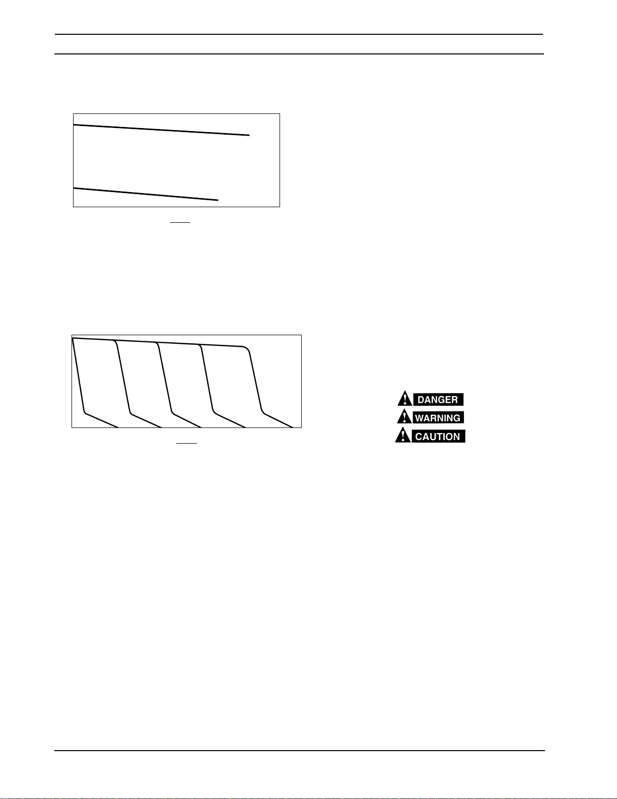
The curves shown in Figure 1-1 represent the voltampere static characteristics for the power source.
The slant of these curves is referred to as the "slope"
and is generally defined as the "voltage drop per 100
amperes of current use". These curves show the
output voltage available at any given output current
from the minimum to the maximum setting of the
voltage control. Because the volt-ampere slope is
fixed, it is possible to select welding conditions by
estimating the open-circuit voltage required for the
load current when operating in the CV mode.
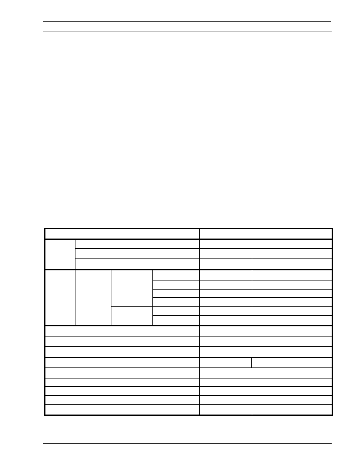
Table 1-1. Specifications for 653CV
OPEN CIRCUIT VOLTAGE (U0) 54 vdc (cv)/59 vdc (cc)
RATED DUTY CYCLE 60% 100%
OUTPUT Current (I2) 750 A 650 A (60Hz)/600 A (50Hz)
Voltage (U2) 44 V 44 V
RATED 3 Phase 60 Hz Volts (U1) Current (I1) Flat Current (I1) Flat
INPUT 230 V 124 A 108 A
460 V 62 A 54 A
575 V 50 A 43 A
50 Hz 220 V 127 A 102 A
400 V 70 A 56 A
Power Factor at Rated Output 83%
Output Range 750 A/44 V - 50 A/14 V
Auxiliary Power 115 V ac @ 10 A, 60 Hz
PHYSICAL SPECIFICATIONS 60 Hz. 50 Hz.
Height (without lift eye) 25.0 (62.2 cm)
Width 18.8 (48.3 cm)
Depth 32.5 (81.9 cm)
Net Weight 493 lbs (224 kg) 528 lbs (240 kg)
Shipping Weight 503 lbs (228 kg) 538 lbs (244 kg)
NOTE: The 653cv may also operate from a 200 (208)-volt a.c. primary input using the 230-volt changeover connections. However,
when connected to this source (200-volt), the output voltage is derated from 38-volts to 35-volts @ 450 amps.
7
Page 8
DESCRIPTIONSECTION 1
1.4 OPTIONAL ACCESSORIES
653cv
Volts
60
50
40
30
Volts
20
10
60
50
40
30
20
10
0
100 200
0
MIN.
300 400 600
D.C. OUTPUT CURRENT (AMPS)
CV MODE FOR MIG/SUB ARC
AMPS
Figure 1-1. Volt-Ampere Curves
0
100
0
200 300 400 600
D.C. OUTPUT CURRENT (AMPS)
CC MODE FOR STICK/ARC GOUGING/SUB ARC
500
AMPS
MAX.
700
700
800500
800
900
900
1.4.1 TR-29 Truck Kit (Item No. 37924)
This truck kit provides complete mobility of the power
source. The kit consists of castors, rear cylinder rack
and wheels, gas cylinder bracket, cylinder chain, and
pull handle.
1.4.2 Swivel Mount Kit (Item No. 36172)
This kit allows TAFA wire feeders with swivel base
mounts to be mounted to the top of the power source
on an insulated swivel mount. This allows the feeder
to freely rotate, relieving potential wire feed problems
while increasing the working area of the Mig Gun.
1.4.3 Automatic Fan Kit (Item No. 36707)
With this kit installed, the fan will start to operate when
the welding arc is initiated and will continue to run for
5 minutes after the arc has been established.
1.5 SAFETY
Before the equipment is put into operation, the safety
section at the front of this manual should be read
completely. This will help avoid possible injury due to
misuse or improper installation.
The definitions relating to the:
1000
safety notations are described at the end of the Safety
Section in the front of this manual read them and
their specific text references carefully.
Figure 1-2. Duty Cycle Curves
8
Page 9
SECTION 2
2.1 LOCATION
A proper installation site is necessary for the power
source to provide dependable service. A proper installation site permits freedom of air movement
through the unit while minimizing exposure to dust,
dirt, moisture, and corrosive vapors. A minimum of 18
inches (46 cm) is required between the side and rear
panels of the power source and the nearest obstruction. The selected site should also allow easy removal of the power source outer enclosure for maintenance. See Table 1-1 for overall dimensions of the
unit.
2.2 RECEIVING, UNPACKING AND
PLACEMENT
A. Immediately upon receipt of the power
source, inspect for damage which may have
occurred in transit. Notify the carrier of any
defects or damage.
B. Remove the power source from the con-
tainer. Remove all packing materials. Check
the container for any loose parts.
C. Check air passages at front and rear of
cabinet, making sure that no packing materials that may obstruct air flow through the
power source.
D. Install the lifting ring furnished with the power
sources into the top of the unit.
For lifting purposes and for keeping dust, moisture, and other foreign material from entering the
power source, the lifting eyebolt must be fully
tightened with a tool.
E. After selecting an installation site (see para-
graph 2.1), place the power source in the
desired location. The unit may be lifted either
by using the lifting ring or by forklift truck. If
a forklift is used for lifting the unit, be sure that
the lift forks are long enough to extend completely under the base.
Do not use filters on this unit as they would
restrict the volume of intake air required for
proper cooling. Output ratings on this unit are
based on an unobstructed supply of cooling air
drawn over its internal components. Warranty is
void if any type of filtering device is used.
2.3 PRIMARY (INPUT) ELECTRICAL
CONNECTION
This power source is a three-phase unit and must be
connected to a three-phase power supply. It is recommended that the unit be operated on a dedicated
circuit to prevent impairment of performance due to
an overloaded circuit.
INSTALLATION
ELECTRIC SHOCK CAN KILL! Before making
electrical input connections to the power source,
"Machinery Lockout Procedures" should be employed. If the connections are to be made from a
line disconnect switch, place the switch in the off
position and padlock it to prevent inadvertent
tripping . If the connection is made from a fusebox,
remove the corresponding fuses and padlock the
box cover. If it is not possible to use padlocks,
attach a red tag to the line disconnect switch (or
fuse box) warning others that the circuit is being
worked on.
A. The primary power leads must be insulated
copper conductors. Three power leads and
one ground wire are required. Either rubber
covered cable or conduit (flexible or solid)
may be used. Table 2-1 provides recommended input conductors and line fuse sizes.
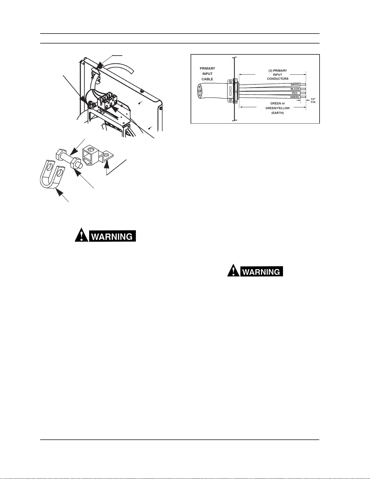
B. Remove the top cover. Identify primary
power connections, TB3, and the ground lug
located on the fan bracket. Refer to figure
2.1.
353cv
Table 2-1A. Recommended Sizes for Input
Conductors and Line Fuses
Rated Input
at 100% Duty Cycle Rating
Volts Amps
208
220
230
400
460
575
* Sized per National Code for 80 °C rated copper conductors @ 30 °C
ambient. Not more than three conductors in raceway or cable. Local
codes should be followed if they specify sizes other than those listed
above.
** Wire per National Electric Code Table 310-16 using 90° C rated conduc-
tors (e.g. THW-2, THWN, THHN).
55
52
50
29
25
20
C. Refer to Figure 2.1 for proper cable strip
lengths. It is important to follow the cable
strip guide to ensure that if the primary input
cable is ever pulled from the strain relief, the
input conductors will be pulled from their
connections before the ground lead is pulled
from the ground lug.
Input &
GND
Conductor*
CU/AWG
No. 8
No. 8
No. 8
No. 12
No. 14
No. 14
Fuse Size
Amps
90
80
80
40
40
30
9
Page 10
SECTION 2
Rear Panel (Inside View)
INSTALLATION
Recommended Cable Strip Lengths
Strain Relief
Ground Fault
Switch*
SWITCH
TB3 Located on
Fan Bracket
GROUND LUG
NUT
HORSESHOE
Figure 2-1. Connecting Primary Power Leads
The chassis must be connected to an approved
electrical ground. Failure to do so may result in
electrical shock, severe burns or death.
5"
10"
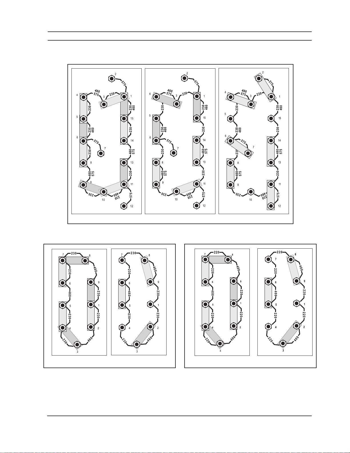
G. Figure 2-2 illustrates the input voltage termi-
nal board and the input voltage link connections. The particular voltages from which this
power source may be operated are stated on
the rating plate. The voltage links were factory set for highest voltage stated on the
rating plate. If the power source is to be
operated on another stated input voltage, the
links must be reset for that particular input
voltage. Always verify the input voltage and
check the link arrangement regardless of
factory setting. The voltage links are set up
by reconfiguring the copper link bars to the
voltage designations for the desired voltage.
2.4 OUTPUT WELDING CONNECTIONS
(SECONDARY)
D. Thread the properly stripped input and ground
conductors through the large strain relief in
the rear panel of the power source. Connect
the three input conductors to the three input
terminals on TB3 (see figure 2-1). To connect
the ground conductor, first remove the ground
fault switch from the ground lug by removing
the nut at the end of the switch and sliding the
switch out of the horseshoe . Connect the
ground conductor to the ground lug, and then
return the ground fault switch to its original
position. *Make sure that the input
conductors do not come in contact with
the ground fault switch.
E. IMPORTANT – Do not tie wrap the input
conductors to the ground conductor as this
can prevent the ground connector from pulling
out last in the event of the input cable being
pulled out of the strain relief.
F. Check all connections for proper tightness.
Ensure all connections are correct and wellinsulated.
Before making any connections to the power
source output terminals, make sure that all primary input power to the machine is off.
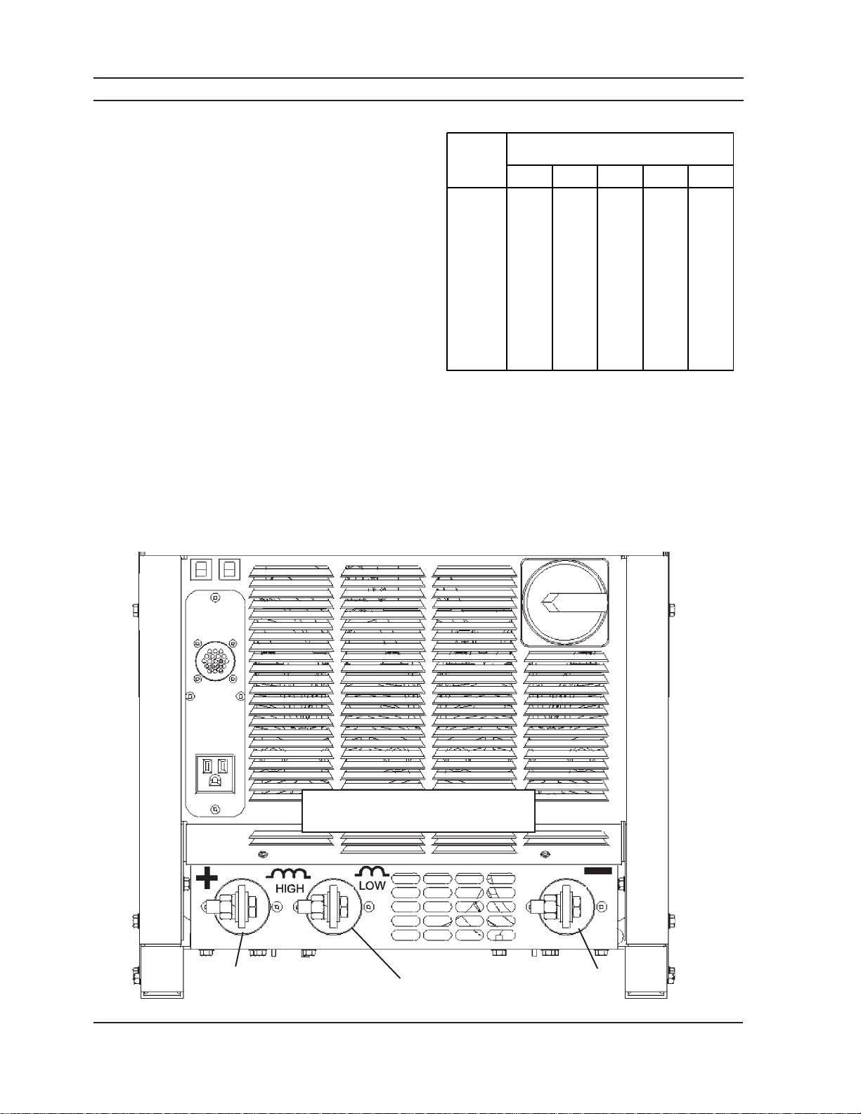
The output connections are located on the front panel
(Figure 2-3). The negative connection is located at
the bottom right corner and the positive (high inductance and low inductance) connections are located at
the bottom left corner. Table 2-2 provides the recommended cable output sizes.
2.5 CONTROL CONNECTIONS
The wire feeder receptacle and 115 VAC Auxiliary
control are mounted on a removable plate. This plate
may be exchanged for different applications.
Optional Available Plates:
• Blank
• Terminal Block
• Miller 14 pin Feeder Receptacle
Refer to Figure 2-3.
10
Page 11
SECTION 2
INSTALLATION
230 Vac Input 460 Vac Input 575 Vac Input
Input T erminal Board Configuration for 230/460/575 Model
(
factory supplied in the 575 configuration)
230 Vac Input
Input T erminal Board Configuration 230/460 Model
factory supplied in the 460 configuration)
(
460 Vac Input
*
*
*
220 Vac Input
Input T erminal Board Configuration 220/400 Model
(
factory supplied in the 400 configuration)
400 Vac Input
Figure 2-2. Input Terminal Boards
11
Page 12
SECTION 2
2.5.1 Remote Control (Optional)
This function is provided by an optional 14-pin receptacle (J2) located on the front panel directly below
connector J1. It receives a mating plug from a Hand
Control Assembly (optional). This receptacle is operative only if the panel remote switch on the power source
front panel is in the "Remote" position.
2.5.2 Auxiliary 115 V AC Receptacle
A 115 Vac receptacle is provided to supply power to
accessories such as a water cooler, heated CO
regulator, or small hand tools. The receptacle is rated
115 Vac / 10 amps.
2.5.3 - 42V Circuit Breaker (CB1)
The 42V resettable circuit breaker (CB1) protects the
42 volt wire feeder/control circuitry against over current. (Table 5-2 provides troubleshooting information).
2.5.4 - 115V Circuit Breaker (CB2)
The 115V resettable circuit breaker (CB2) protects the
115 volt auxiliary receptacle and wire feeder/control
circuitry against over current. (Table 5-2 provides
troubleshooting information).
INSTALLATION
Table 2-2. Output Cable Sizes (Secondary)
Welding
Current
50 100 150 200 250
100
150
200
250
300
2
400
500
600
700
* Total cable length includes work and electrode cables. Cable size is based
on direct current, insulated copper conductors, 100-percent duty cycle and
a voltage drop of 4 or less volts. The welding cable insulator must have a
voltage rating that is high enough to withstand the open circuit voltage of
the power source.
6
4
3
2
1
2/0
3/0
2-2/0
2-3/0
2.5.5 External Grounding Conductor Protection
This feature will de-energize the power source output if
current flow is detected in the external ground conductor. When this happens, the Fault light on the front
control panel will light. It will remain lit until the fault is
corrected or the power source power switch (S1) is
turned off.
Total Length (Feet) of
Cable in Weld Circuit*
4
3
1
1/0
2/0
3/0
3/0
2-2/0
2-3/0
3
1
1/0
2/0
3/0
4/0
4/0
2-3/0
2-3/0
2
1/0
2/0
3/0
4/0
4/0
2-2/0
2-3/0
2-4/0
1/0
2/0
3/0
4/0
4/0
2-2/0
2-3/0
2-4/0
2-4/0
2.4
High Inductance for
Positive Output
Receptacle
Figure 2-3. Connection Diagram
2.4
Low Inductance for
Positive Output
Receptacle
12
2.4
Negative
Output
Receptacle
Page 13
SECTION 3
Never operate the power source with the cover
removed. In addition to the safety hazards, improper cooling may cause damage to the components. Keep side panels closed when unit is
energized. Welding helmet, gloves, and other
personal protection should always be worn when
welding.
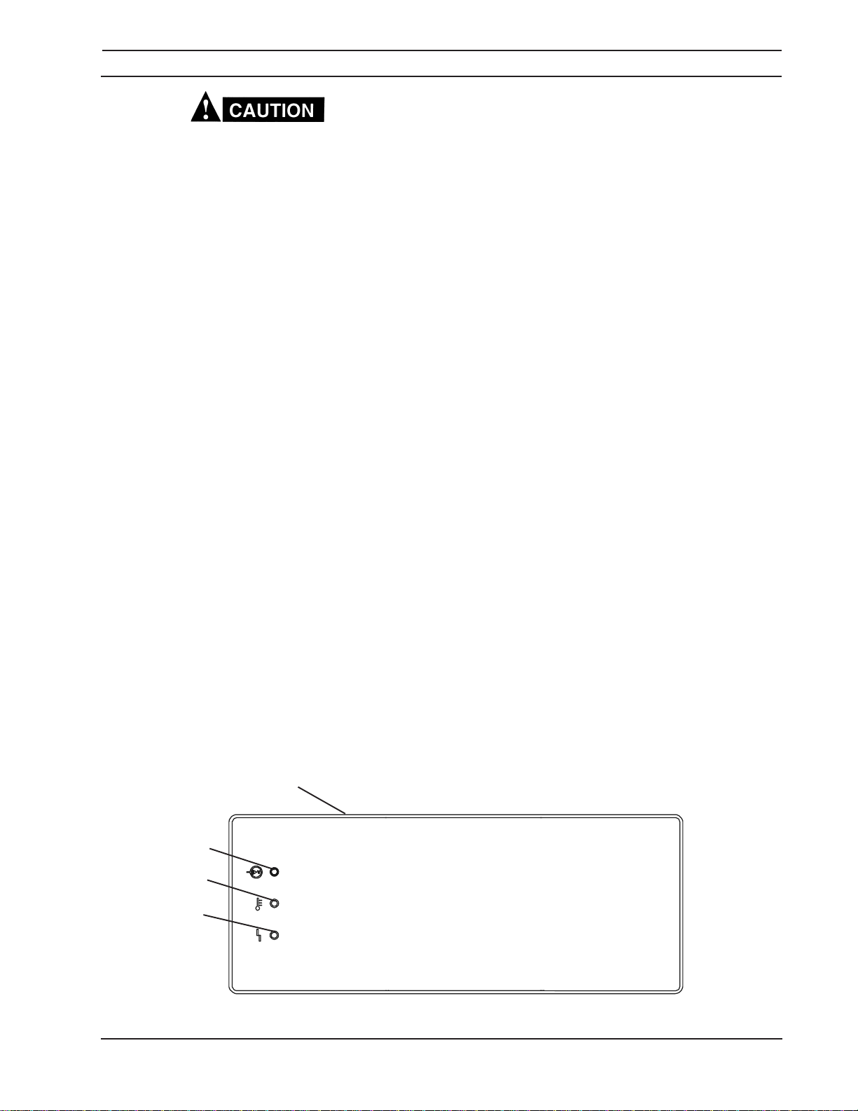
3.1 CONTROLS (See Figure 3-1)
3.1.1 Power Switch (ON-OFF)/(I-O)
The power switch is located on the front panel of the
power source. In the "off" ("O") position, the unit is
shut down; however, power is still present in the unit.
To fully shut down the power source, power must be
disconnected at the line disconnect switch or the fuse
box.
With the switch in the "on" ("I") position, power is
provided to the main transformer and the low voltage
control circuitry.
3.1.1.1 Power Indicator
This white light will indicate that the power switch is in
the on position and power has been applied to the
main transformer and low voltage circuitry.
3.1.1.2 Over Temperature Indicator (Temp.)
This amber light will indicate when an internal overheating condition has occurred and one of the ther-
OPERATION
mal switches has opened. User control of the solid
state contactor will be interrupted and power source
output will shut down to protect critical components.
Once cooled to a safe temperature, the thermal
switch will automatically reset and output control will
be restored.
3.1.1.3 Fault Indicator
This red light, when lit, will signal that current was
flowing through the external ground conductor. It will
also light if a short occurs (momentary or permanent)
between the +12 volt J1-E; the +10 volt (J2-E) and
either the chassis ground or the negative terminal of
the power source. The power source output terminals
are de-energized and the fault must be corrected
before resuming operation.
3.1.6 Over Current Protection
The 653CV incorporates automatic over current protection. If an over current condition occurs, the automatic circuitry will fold back the output current to a
level that will prevent damage to the power source.
The power source will remain in this low current fold
back mode until the arc is broken, the torch trigger is
released or the contactor switch is reset.
3.1.7 High & Low Inductance Receptacles
The 653CV provides high and low inductance output
connections (see figure 2-3). Both are positive output
terminals. The high inductance terminal slows the
power source dynamic response. This means the
output current will build at a slower rate compared to
the low inductance terminals.
3.1.1 (on rear panel)
3.1.1.1
3.1.2
3.1.3
POWER
TEMP
FAULT
Figure 3-1. Control Locations
13
Page 14
SECTION 4
MAINTENANCE
4.1 GENERAL
If this power source does not operate properly,
stop work immediately and investigate the cause
of the malfunction. Maintenance work must be
performed by an experienced person, and electrical work by a trained electrician. Do not permit
untrained persons to inspect, clean, or repair this
power source. Use only recommended replacement parts.
Be sure that the branch circuit or main disconnect switch is off, or electrical input fuses are
removed, before attempting any inspection or
work inside the power source. Placing the power
switch in the off position does not remove all
power from inside the power source.
4.2 CLEANING
Periodically, remove the cover from the power source
and blow accumulated dust and dirt from the air
passages and interior components by using clean,
dry low pressure air. The frequency of cleaning
required depends upon the environment in which the
power source is used.
It is imperative that all air passages be kept as clean
as possible in order to allow adequate air flow to
provide proper cooling.
After cleaning with low pressure air, check for and
tighten any loose hardware, including all electrical
connections. Check for frayed and/or cracked insulation on all power cables and replace if necessary.
Failure to replace worn or damaged cables may
result in a bare cable touching a grounded object.
The resulting electrical arc may injure unprotected eyes and will present a serious fire hazard.
Body contact with a bare cable, connector, or
conductor may result in severe electrical shock,
causing serious burns or death.
4.3 INSPECTION AND SERVICE
Keep the power source dry, free of oil and grease,
and protected at all times from damage by hot metal
and sparks.
4.3.1 Fan Motor
Keep the fan motor free of accumulated dust and lint.
4.3.2 Transformer
Other than periodically cleaning the dust and dirt from
the transformer, no maintenance is required. Ensure
that only clean, dry, low pressure air is used.
4.3.3 Wire Feeder and Control Circuits
These circuits are protected by two 10 amp circuit
breakers mounted in the front panel. If these open,
the contactor and wire feeder will not operate.
4.3.4 Over Temperature Protection
If the power source reaches an abnormally high
internal temperature, the thermal protection will
deenergize the contactor circuit, shutting down the
power source but leaving the cooling fan on. After the
power source has cooled to a safe level, the thermal
protection will automatically reset. While deenergized,
the contactor and wire feeder cannot be operated.
4.3.5 Digital Voltmeter/Ammeter Calibration
To verify the accuracy of the digital volt/ammeter
combination, the following calibration procedure can
be performed periodically:
1. Place the Panel/Remote switch in Panel position.
2. Disconnect cables from the output terminals and
then connect an accurate DC voltmeter to the
output terminals.
3. Place the Contactor switch in the On position.
4. With the primary input power on, turn the Voltage
control knob until you get 25V on the DC voltmeter. Compare the reading with the reading on the
digital voltmeter on the front panel.
5. If there is a difference in the voltage readings,
open front control panel by removing the two
mounting screws from the upper corners, remove meter board from its four mounting posts,
and adjust the trimpot (R13) on the meter board
with a small screwdriver until the digital meter
reading matches the DC voltmeter reading. When
satisfied, reassemble meter board and front control panel.
14
Page 15
SECTION 5
TROUBLESHOOTING
5.1 GENERAL
DISCONNECT primary power at wall switch, or
circuit breaker, before attempting inspection or
work inside the power source.
If the power source is operating improperly, the
following troubleshooting information may be used to
locate the source of the trouble.
Check the problem against the symptoms in the
following troubleshooting guide (Table 5-2.) The
remedy for the problem may be quite simple. If the
cause cannot be quickly located, open up the unit and
perform a simple visual inspection of all the components and wiring. Check for proper terminal connections, loose or burned wiring or components, blown
fuses, bulged or leaking capacitors, or any other sign
of damage or discoloration.
5.2 TESTING AND REPLACING BRIDGE
ASSEMBLY COMPONENTS
6. Check the gate circuit on the SCRs by installing a jumper from the gate lead to the anode
of the SCR. The meter should read less than
5 ohms. Remove the jumper from the gate.
The meter reading should increase (30-50
ohms).
IMPORTANT
When replacing SCRs, make sure mounting surfaces are clean. Using Alcoa No. 2 EJC Electrical
Joint Compound or an equivalent, apply a thin coat
to the SCR mounting surface and positively locate in
place on the heatsinks. Place the clamp in position
with the bolts through the holes in the heatsinks and
proceed as follows:
1. Tighten the bolts evenly until finger tight, insuring that the nuts are not rotating.
2. Tighten the bolts 3/4 turn plus an 1/8 turn using
a socket wrench on the bolt heads and rotating
only in 1/4 turn increments plus 1/8 turn alternating between the bolts noting that the nuts are
not rotating.
The SCRs used in the power source are devices
which allow current to flow in only one direction. The
SCRs are designed to provide long trouble-free operation; however, should a failure occur, they may
require replacement.
A. Testing SCRs.
1. Remove top and right side panel from the
power source.
2. Locate the main rectifier assembly containing the SCRs.
3. Electrically isolate main bridge assembly by
disconnecting resistor R5.
4. With the ohmmeter on RX1 scale, place the
positive lead on the anode (end of SCR with
screw threads) and the negative lead on the
cathode (positive output terminal on the front
panel). The meter should read minimum of
20 meg ohms.
5. Reverse leads and check each SCR. All
readings should again show high resistance.
The SCRs are bad if they show low resistance in either direction.
Table 5-1. PCB Voltage Tests*
NOTE
All voltage readings are taken with the front access
panel open and the power switch "ON".
Electrical service and repair should be attempted
only by a trained electrician.
653cv
SCR VOLTAGES (OUTPUT)
FROM TO READING
P8-5 OTB+ +10 V dc
P8-7 OTB+ 0-10 V dc**
P6-6 (SCR1)
P6-5 (SCR2)
P6-4 (SCR3)
P6-3 (SCR4)
P6-2 (SCR5)
P6-1 (SCR6)
* Refer to Schematic Diagram
** Varies with VCP (R1)
OTB+ .3 V dc with
contactor on
15
Page 16
SECTION 5
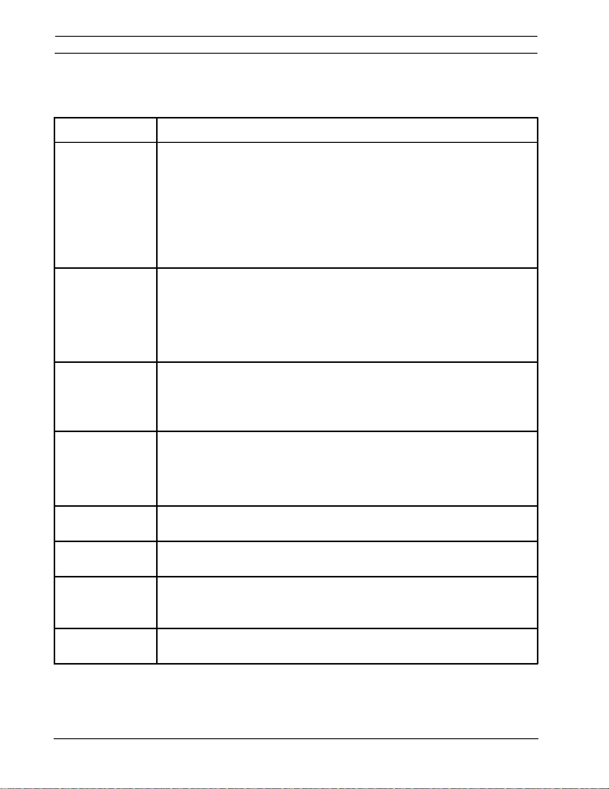
Table 5-2. Troubleshooting Guide
CONDITION ACTION
TROUBLESHOOTING
Unit Inoperative A.
B.
C.
D.
E.
F.
G.
No Output -- Fan
Running
Limited Output or
Low Open-Circuit
Voltage
A.
B.
C.
D.
E.
A.
B.
C.
D.
No input power. Check main line (user’s) switch fuses --replace if needed.
Loss of primary phase. Check that LED on control PCB is lit. If not, find & replace
defective fuse.
Poor or improper input (terminal board) connections.
Defective on/off switch on rear panel -- replace.
Main transformer overheating. Also check for proper cooling, proper primary
hookup, or shorted turn on secondary.
Fan motor not operating -- check motor and leads.
Ground fault indicator "ON". - C heck for cause and correct. Turn power switch
"OFF" then "ON" to reset.
Poor or improper electrical input -- check input connections on TB.
Poor connections at output terminals/work station -- check, tighten or replace.
Main transformer overheating -- thermal switches tripped due to restricted cooling
air. Temperature light on front panel will be lit. Let unit cool down.
Solid-state breaker tripped due to current overload.
PC board defective or loose PC board connector(s) -- if loose, reinsert; if
defective, replace.
Input voltage jumper links on terminal board improperly set. Check for proper
voltage.
Poor output connections. Take apart, clean, and reassemble.
Unit may be single phasing -- check incoming power for three phases.
Panel-Remote switch in Remote position and remote voltage pot disabled.
Erratic Current A.
B.
C.
D.
E.
High Output, No
Voltage Control
No 115 Volt ac
Output
Line Fuse Blows
When Power Source
is First Turned On
Wire Feeder is
Inoperative
A. PC board defective or loose -- reset and/or replace board.
A. Ci rcuit breaker tripped. Check 42V C B1 and 115V C B2 -- Reset.
A.B.Shorted SCR in Main Bridge-- replace.
A. Loose feeder control cable -- Check and tighten all connections.
Cable size too small -- use correct cables.
Loo se cable connection (wi ll usually get hot) -- ti ghten connections.
Improper wire feeder setup.
Defective SCR in bridge rectifier.
PC board defective -- replace.
Shorted capacitor in Capacitor Bank.
16
Page 17

SECTION 6
6.1 GENERAL
Always provide the series or serial number of the unit on which the parts will be used. The serial number is stamped
on the unit nameplate.
REPLACEMENT PARTS
17
Page 18
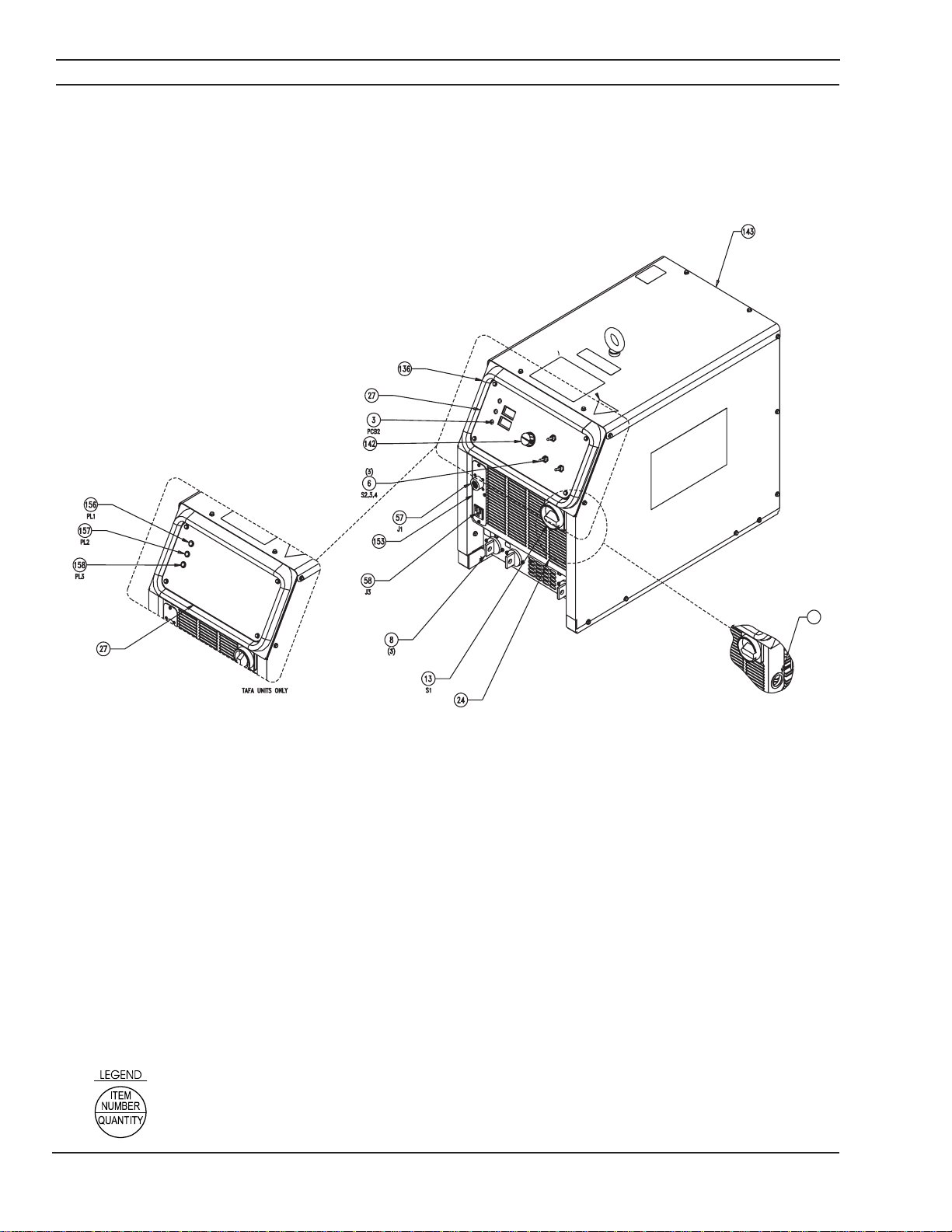
SECTION 6
REPLACEMENT PARTS
View 1 - 653cv
45
18
Page 19
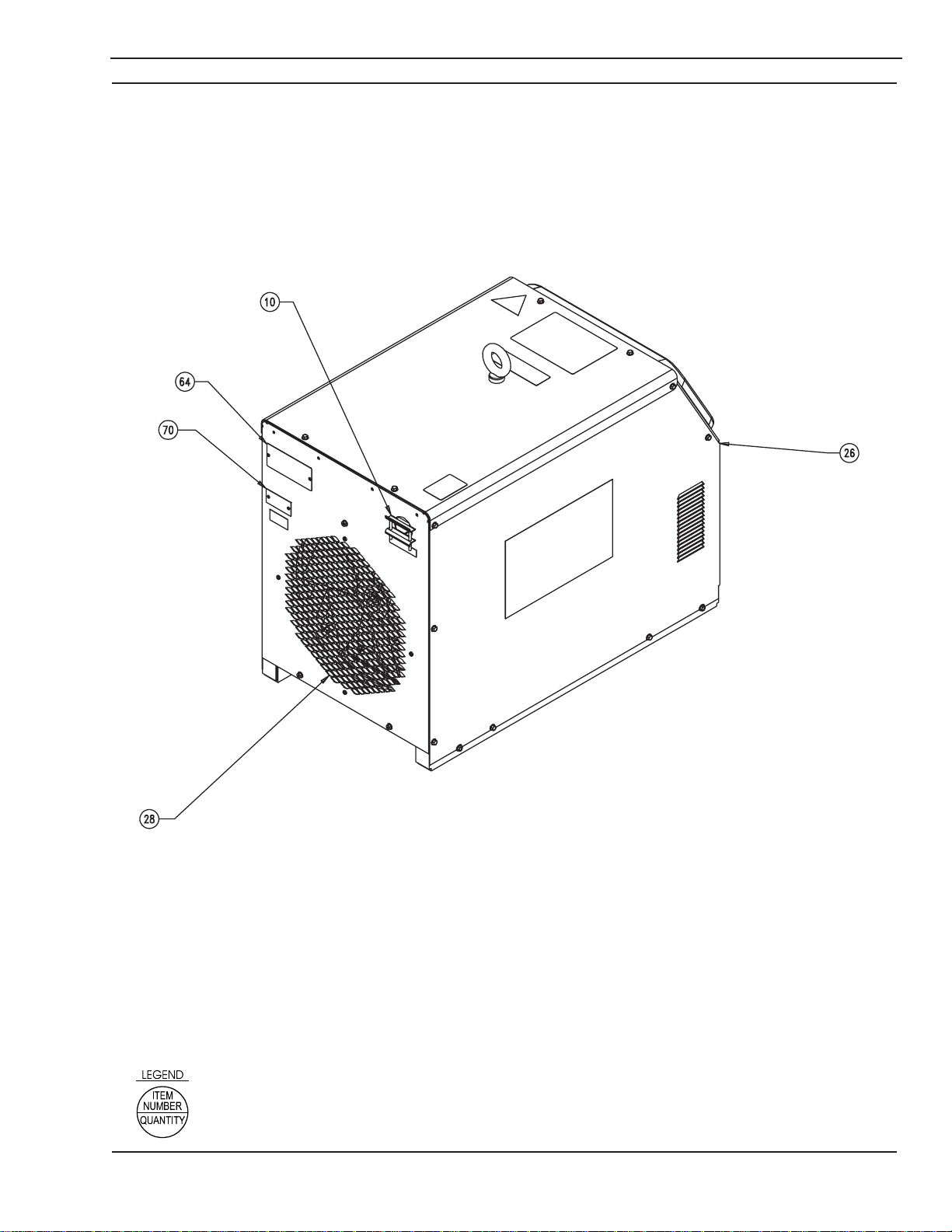
SECTION 6
REPLACEMENT PARTS
View 2 - 653cv
19
Page 20
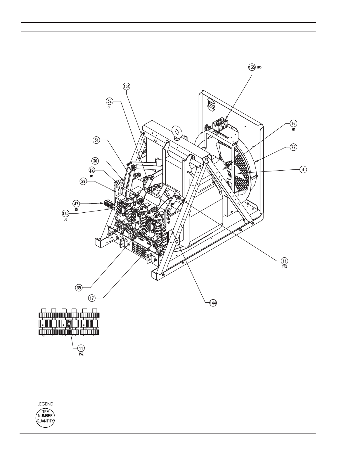
SECTION 6
REPLACEMENT PARTS
View 3 - 653cv
20
Page 21
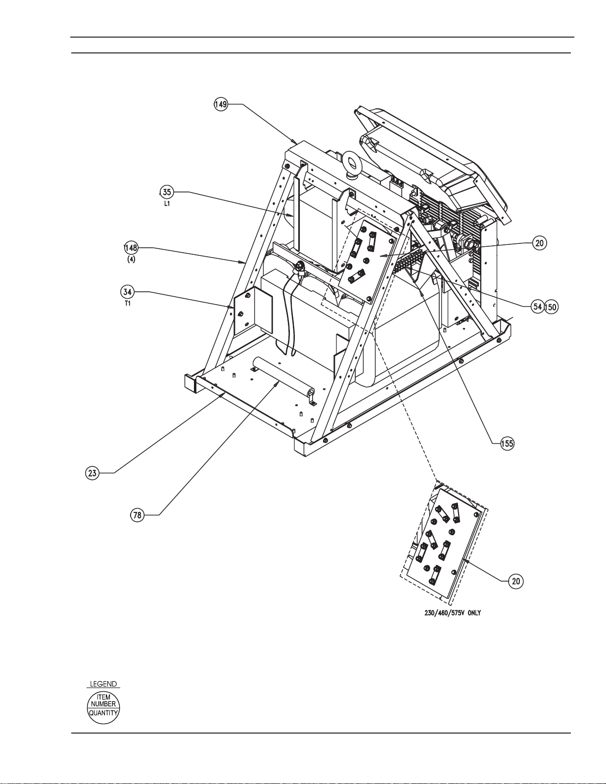
SECTION 6
REPLACEMENT PARTS
View 4 - 653cv
21
Page 22
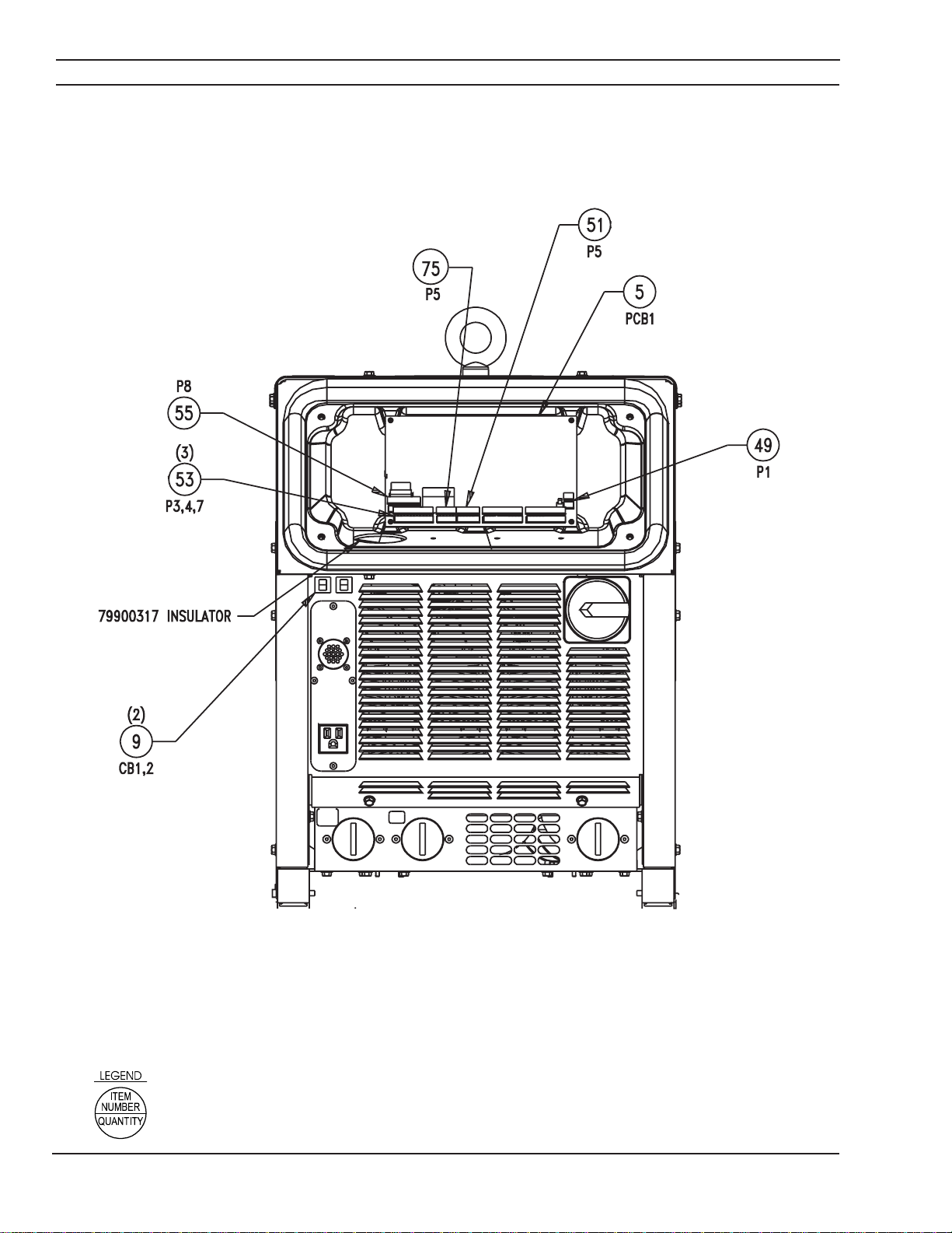
SECTION 6
REPLACEMENT PARTS
View 5 - 653cv
22
Page 23
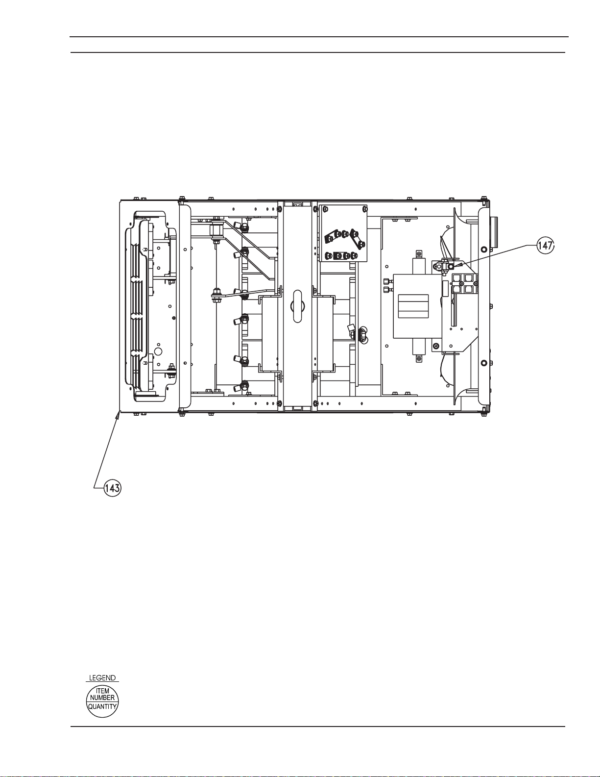
SECTION 6
REPLACEMENT PARTS
View 6 - 653cv
23
Page 24
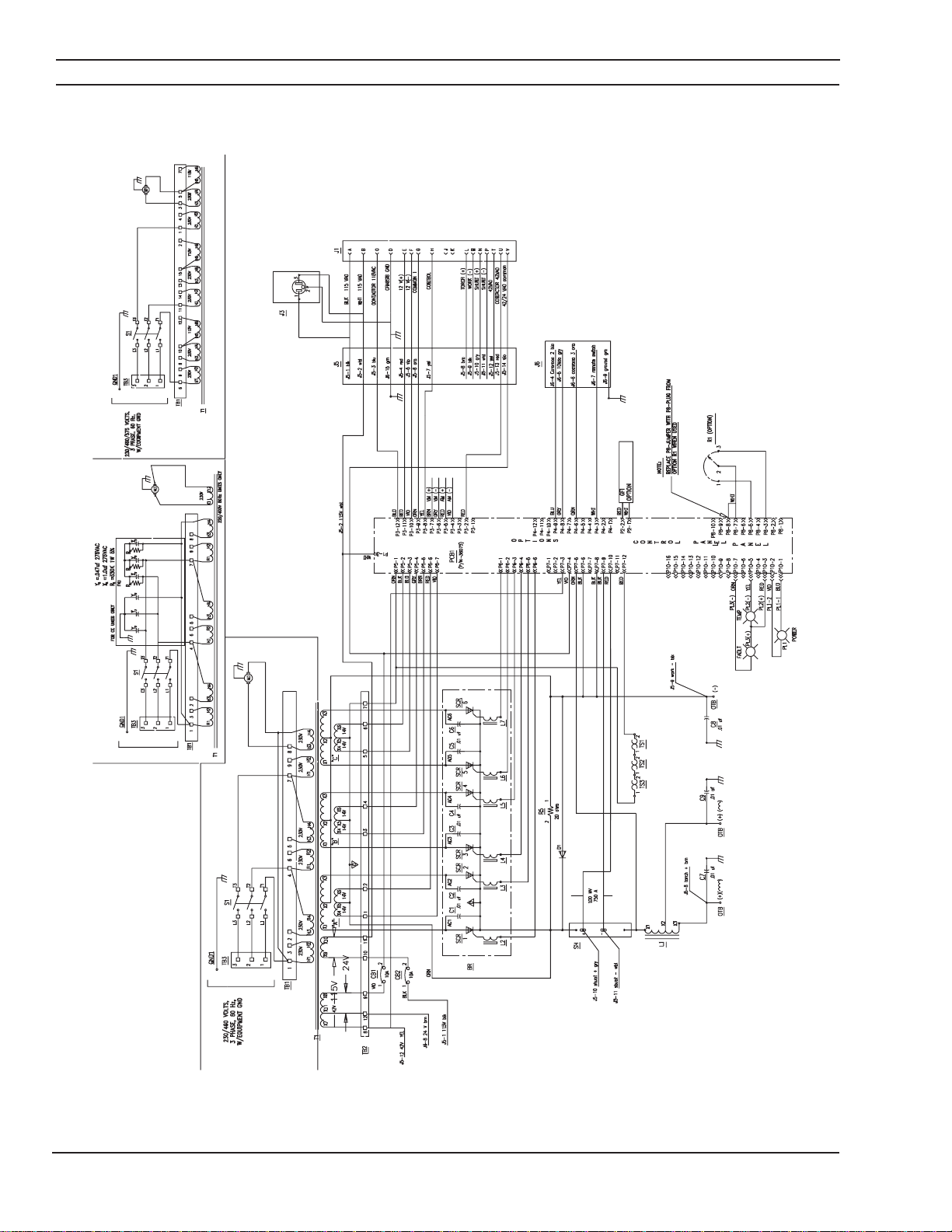
SECTION 6
REPLACEMENT PARTS
D-0558001208
653cv Schematic Diagram - 230/460, 60Hz
24
Page 25
SECTION 6
REPLACEMENT PARTS
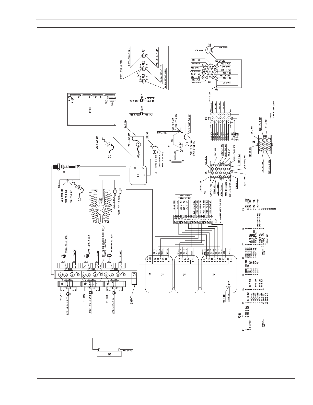
D-0558001209
653cv Wiring Diagram - 220/400/230/460/575, 50/60Hz
25
Page 26
SECTION 6
REPLACEMENT PARTS
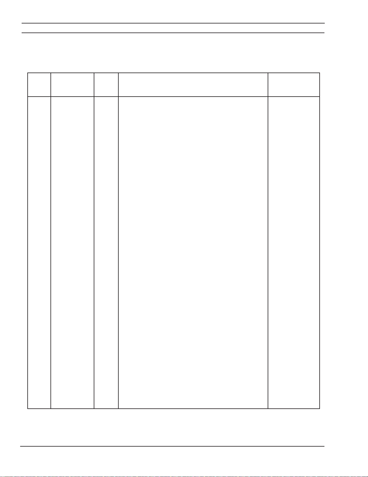
Bill of Materials
653cv DC Welding Power Source
ITEM PART OR
NO. CODE NO. QTY. DESCRIPTION SYMBOL
3 36121 PCB DIGITAL METER PCB2
4 36173 1 BLADE FAN 14"
5 38130 1 PCB CONTROL PCB1
6 634515 SW TGGL SPOT 2 POS 15A 125V S2,3,4
8 678025 3 TERM AY
9 950122 2 CKT BREAKER 10A 32VDC 250VAC CB1,2
10 950219 1 RELIEF STRAIN 2.00
11 950711 2 SW THERMAL 194F TS2,3
12 950768 1 DIODE FWD 300V 300A D1
13 950945 1 SW PWR DISC 100A 600V S1
16 2062334 1 MOTOR FAN 1/3 HP 1625RPM MI
17 80558001024 3 SCR ASSY
20 36091 1 BOARD INPUT TERMINAL 230/460V
36110 1 BOARD INPUT TERMINAL 230/460/575V
32236 1 BOARD INPUT TERMINAL 220/400V
23 37861BK 1 BASE TAFA
24 37862BK 1 PANEL FRONT BOTTOM TAFA
25 37863TGY 1 PANEL RIGHT SIDE TAFA
26 37864TGY 1 PANEL LEFT SIDE TAFA
27 32307BK 1 OVERLAY PANEL TAFA
28 378678K 1 PANEL REAR TAFA
29 37868 1 BRIDGE BUSBAR
30 37869 1 HIGH TAP INDUCTOR BUSBAR
31 37870 1 LOW TAP INDUCTOR BUSBAR
32 37871 1 SHUNT SHUNT
34 37882 1 XFMR MAIN 230/460T1
37890 1 XFMR MAIN 230/460/575VT1
37892 1 XFMR MAIN 220/400T1
35 37883 1 INDUCTOR L1
36 0558001208 REF SCHEMATIC DIAG 653 TAFA
37 0558001209 REF WIRING DIAG SEC 653 TAFA
45 950167 1 GROMET TUB 1.12 ID X 1.50 GD X .06 W
47 951504 1 PLUG HOUSING 15 POS J5
49 952067 1 CONNECTOR 20 AWG 3 PIN P1
51 952070 1 CONNECTOR 20 AWG 7 PIN P5
53 952072 1 CONNECTOR 20 AWG 12 PIN P3,4,7
54 952073 1 TERM BLOCK 12 POS
55 952081 1 CONNECTOR 20 AWG 10 PIN P8
57 952209 1 PANEL RECEPTACLE 19 PIN F J1
58 952219 1 OUTLET 110V SQUARE J3
64 954822 1 LABEL RATING 653 CVCC 230/460
954846 1 LABEL RATING 653 CVCC 230/460/575
954847 1 LABEL RATING 653 CVCC 220/400
69 13730632 1 POT LIN 1OK 2W .88L
70 13730763 1 NAME PLATE CODE SERIAL STOCK
75 13735311 1 CONNECTOR 20 AWG 6 PIN P6
26
Page 27

SECTION 6
REPLACEMENT PARTS
Bill of Materials
653cv DC Welding Power Source (Cont'd)
ITEM PART OR
NO. CODE NO. QTY. DESCRIPTION SYMBOL
77 13735508 1 SHROUD FAN
78 17300020 1 RES RW FIXD ST 30OW 10% 20.00
135 0558001010 1 TERMINAL BLOCK 3 POS TB3
136 0558001033 BOX PCB BLACK
140 0558001016 1 CAP 9 FOS J6
142 0558001019 KNOB 1.57 DIA
143 05580010328K 1 PANEL FRONT TOP TAFA
144 0558001038 1 INSULATOR
147 360430K BRACKET FAN TAFA
148 360488K 4 LEG AFRAME TAFA
149 36049BK 1 BAIL LIFTING TAFA
150 360708K 1 BRACKET TERMINAL BOARD MTG TAFA
151 36140 1 BAFFLE
152 37902BK 1 BLANKING PLATE TAFA
153 379018K 1 19 AND 1 10V PANEL TAFA
154 0558001338TGY 1 PANEL TOP TAFA
155 37899 1 LOWER BAFFLE
156 13792157 1 LAMP WHITE 48Y PL1
157 951754 1 LAMP LED YEL 12V PL2
158 952610 1 LABEL CE
162 954565 1 STAND OFF 1/4-20 X .75
164 0558001331BK 1 HINGE ACCESS
165 0558001337 1 PANEL ACCESS BLACK
2062211 1 THERMOSTAT (Not Shown)
27
Page 28

SECTION 6
REPLACEMENT PARTS
NOTES
28
Page 29

SECTION 6
NOTES
REPLACEMENT PARTS
29
Page 30

NOTES
30
Page 31
Page 32

F15-598-A 05 / 2003 Printed in USA
 Loading...