

Page 1

SPARCbook
Portable Workstation
User Guide
SPARCbook 3000 and SPARCbook 3 Families
Page 2

Copyright and Trademark Information
Copyright and Trademark Information
Copyright © 1997 by Tadpole Technology Inc
Copyright © 1995 by Sun Microsystems, Inc. 2550 Garcia Avenue, Mountain View, California 94043-1100 U.S.A.
All rights reserved. This product or document is protected by copyright and distributed under licenses restricting its use, copying,
distribution and decompilation. No part of this product or document may be reproduced in any form by any means without prior
written authorization of Sun and its licensors, if any.
Portions of this product may be derived from the UNIX®, licensed from UNIX Systems Laboratories, Inc., a wholly owned
subsidiary of Novell, Inc., and from the Berkeley 4.3 BSD system, licensed from the University of California. Third-party software,
incuding font technology in this product, is protected by copyright and licensed from Sun’s Suppliers.
RESTRICTED RIGHTS LEGEND: Use, duplication, or disclosure by the government is subject to restrictions as set forth in
subparagraph (c) (1) (ii) of the Rights in T echnical Data and Computer Software clause at DFARS 252.227-7013 and FAR 52.227-19.
This product or the products depicted herein may be protected by one or more U.S. or international patents or pending patents.
TRADEMARKS
Sun, Sun Microsystems, the Sun logo, OpenWindows, SunView and SunOS are trademarks or registered trademarks of Sun
Microsystems, Inc. UNIX and OPEN LOOK are registered trademarks of UNIX Systems Laboratories, Inc. All other product names
mentioned herein are the trademarks of their respective owners.
All SPARC trademarks, including the SCD Compliant logo, are trademarks or registered trademarks of SPARC International, Inc.
SPARCbook is a trademark of SPARC International Inc, licensed exclusively to Tadpole Technology Inc. Products bearing SPARC
trademarks are based upon an architecture developed by Sun Microsystems, Inc.
The OPEN LOOK® and Sun™ Graphical User Interfaces were developed by Sun Microsystems, Inc. for its users and licensees. Sun
acknowledges the pioneering efforts of Xerox in researching and dev eloping the concept of visual or graphical user interf aces for the
computer industry. Sun holds a non-exclusive license from Xerox to the Xerox Graphical User Interface, which license also covers
Sun’s licensees who implement OPEN LOOK GUI’s and otherwise comply with Sun’s written License agreements.
The X Window System is a trademark of X Consortium, Inc.
Notebook Computing Environment and NCE are trademraks of Tadpole Technology, Inc.
All other products or services mentioned herein are identified by the trademarks, service marks or product names of their respective
companies or organizations.
Issue 1.0 of 12 June 1997 © by Tadpole Technology plc
Part Number: 980380 Printed in United Kingdom
ii
SPARCbook Portable Workstation User Guide
Page 3

FCC Class B Notice
FCC Class B Notice
This equipment has been tested and found to comply with the limits for a Class B digital device, pursuant to
Part 15 of the FCC rules. These limits are designed to provide reasonable protection against harmful
interference in a residential installation. This equipment generates, uses and can radiate radio frequency energy
and, if not installed and used in accordance with the instructions, may cause harmful interference to radio
communications. However, there is no guarantee that interference will not occur in a particular installation. If
this equipment does cause harmful interference to radio or television reception, which can be determined by
turning the equipment off and on, the user is encouraged to try to correct the interference by one or more of the
following measures:
• Reorient or relocate the receiving antenna.
• Increase the separation between the equipment and receiver.
• Connect the equipment into an outlet on a circuit different from that to which the receiver is connected.
• Consult your supplier or an experienced radio or television technician for help.
Properly shielded and grounded cables and connectors must be used in order to meet FCC emission limits.
Proper cables and connectors are available from your supplier. Tadpole Technology is not responsible for any
radio or television interference caused by using other than recommended cables and connectors or by
unauthorized changes or modifications to this equipment. Unauthorized changes or modifications to the
equipment could void the authority granted by the FCC to operate the equipment.
This device complies with Part 15 of the FCC rules. Operation is subject to the following two conditions: (1)
this device may not cause harmful interference, and (2) this device must accept any interference received,
including interference that may cause undesired operation.
IMPORTANT NOTE:
external video monitor, the cable used to connect between this equipment and the external monitor must be of a
ferrite loaded type. If the cable used is not already fitted with ferrite cores, the user must install a split ferrite
core on the cable.
To ensure compliance with the Class B limit, when this equipment is operated with an
Canadian Department of Communications Compliance Statement
This equipment does not exceed Class B limits per radio noise emissions for digital apparatus set out in the
Radio Interference Regulations of the Canadian Department of Communications.
Avis de conformité aux normes du ministerè des Communications du Canada
Cet équipment ne dépasse pas les limites de Classe B d´émission de bruits radioélectroniques pour les appareils
numériques, telles que prescrites par le Règlement sur le brouillage radioélectrique établi par le ministère des
Communications du Canada.
SPARCbook Portable Workstation User Guide
iii
Page 4

FCC Part 68 Modem Information
FCC Part 68 Modem Information
This information applies ONLY to SPARCbook 3, SPARCbook 3 LC, SPARCbook 3XP, SPARCbook 3
TX and SPARCbook Server models which are equipped with an internal modem.
This equipment complies with Part 68 of the FCC rules. On the underside of this equipment is a label that
contains, among other information, the FCC registration number and ringer equivalence number (REN) for this
equipment. If requested, this information must be provided to the telephone company.
This equipment uses the following USOC jacks: RJ12.
The REN is used to determine the quantity of devices which may be connected to the telephone line. Excessive
RENs on the telephone line may result in the devices not ringing in response to an incoming call. In most, but
not all areas, the sum of the RENs should not exceed five (5.0). To be certain of the number of devices that may
be connected to the line, as determined by the total RENs, contact the telephone company to determine the
maximum REN for the calling area.
If this equipment causes harm to the telephone network, the telephone company will notify you in advance that
temporary discontinuance of service may be required. If advance notice is not practical, the telephone company
will notify the customer as soon as possible. Also, you will be advised of your right to file a complaint with the
FCC if you believe it is necessary.
The telephone company may make changes in its facilities, equipment, operations or procedures that could
affect the operation of the equipment. If this happens, the telephone company will provide advance notice in
order for you to make the necessary modifications in order to maintain uninterrupted service.
If trouble is experienced with this equipment, please contact Tadpole Technology Inc., 12012 Technology
Boulevard, Suite 100, Austin, Texas 78727 Tel: 512-219-2200 for repair and/or warranty information. If the
trouble is causing harm to the telephone network, the telephone company may request you remove the
equipment from the network until the problem is resolved.
The following repairs may be done by the customer: None.
This equipment cannot be used on telephone company-provided coin service. Connection to Party Line Service
is subject to state tariffs.
The Telephone Consumer Protection Act of 1991 makes it unlawful for any person to use a computer or any
other electronic device to send messages via a telephone fax machine unless such a message contains in a
margin at the top or bottom of each transmitted page or on the first page of the transmission, the date and time
it is sent and an identification of the business or other entity, or other individual sending the message and the
telephone number of the sending machine or such business, other entity or individual.
In order to program this information into this machine, you should follow the steps described in “FAXtool” on
page 9-22.
iv
SPARCbook Portable Workstation User Guide
Page 5

Electrical Safety Notice
WARNING!
THE AC ADAPTER SUPPLIED WITH YOUR COMPUTER CONTAINS
DANGEROUS VOLTAGES. IT CONTAINS NO USER SERVICEABLE PARTS. DO
NOT REMOVE THE COVER.
The following message applies to SPARCbook 3 models with built-in
modem.
WARNING!
ELECTRICAL CURRENT FROM POWER, TELEPHONE AND
COMMUNICATION CABLES IS HAZARDOUS. TO AVOID SHOCK HAZARD,
CONNECT AND DISCONNECT CABLES AS DESCRIBED BELOW WHEN
INSTALLING, MOVING OR OPENING THE COVERS OF THIS PRODUCT OR
ATTACHED DEVICES.
To connect your computer:
1. Turn your computer and peripherals OFF.
Electrical Safety Notice
2. Connect all cables between your computer and any peripherals.
3. Connect all signal cables; for example, modem cable to a telephone
receptacle.
4. Connect the power cord to the outlet.
5. Turn the peripherals ON and then turn your computer ON.
To disconnect your computer:
1. Turn everything OFF.
2. Disconnect the power cord.
3. Disconnect the signal cables.
4. Disconnect all cables between your computer and peripherals.
SPARCbook Portable Workstation User Guide
v
Page 6

Environmental Notice
Lithium battery
WARNING!
Environmental Notice
Note
THIS UNIT CONTAINS AN INTEGRATED LITHIUM BATTERY WHICH IS NOT
A CUSTOMER SERVICEABLE PART AND MUST NOT BE REPLACED BY THE
CUSTOMER / END USER. IF THE LITHIUM BATTERY REQUIRES
REPLACEMENT, THE UNIT MUST BE RETURNED TO THE FACTORY OF
MANUFACTURE AS THERE IS A DANGER OF EXPLOSION IF THE BATTERY IS
INCORRECTLY REPLACED.
The fluorescent lamp located in the liquid crystal display (LCD) contains a small amount
of mercury. Dispose of it in accordance with your company’s safety procedures, local
procedures or return it to your supplier for safe disposal.
vi
SPARCbook Portable Workstation User Guide
Page 7

Copyright and Trademark Information . . . . . . . . . . . . . . . . . . . . . . . . . . . . . . . . . . ii
FCC Class B Notice . . . . . . . . . . . . . . . . . . . . . . . . . . . . . . . . . . . . . . . . . . . . . . . . iii
FCC Part 68 Modem Information . . . . . . . . . . . . . . . . . . . . . . . . . . . . . . . . . . . . . . iv
Electrical Safety Notice . . . . . . . . . . . . . . . . . . . . . . . . . . . . . . . . . . . . . . . . . . . . . . v
To connect your computer: . . . . . . . . . . . . . . . . . . . . . . . . . . . . . . . . . . . . . . . . v
To disconnect your computer: . . . . . . . . . . . . . . . . . . . . . . . . . . . . . . . . . . . . . . v
Lithium battery . . . . . . . . . . . . . . . . . . . . . . . . . . . . . . . . . . . . . . . . . . . . . . . . . vi
Environmental Notice . . . . . . . . . . . . . . . . . . . . . . . . . . . . . . . . . . . . . . . . . . . . . . . vi
About this Guide
Document Summary . . . . . . . . . . . . . . . . . . . . . . . . . . . . . . . . . . . . . . . . . . . . . . . . xvi
Models Covered by this Guide . . . . . . . . . . . . . . . . . . . . . . . . . . . . . . . . . . . . . . . . xix
Associated Documents . . . . . . . . . . . . . . . . . . . . . . . . . . . . . . . . . . . . . . . . . . . . . . xix
. . . . . . . . . . . . . . . . . . . . . . . . . . . . . . . . . . . . . . . . . . . . . . . . . . . . . . . . . . . . . . xix
Typographical Conventions . . . . . . . . . . . . . . . . . . . . . . . . . . . . . . . . . . . . . . . . . . xx
Chapter 1 Getting Started
Caring for your SPARCbook . . . . . . . . . . . . . . . . . . . . . . . . . . . . . . . . . . . . . . . . . 1-2
Installing the Battery . . . . . . . . . . . . . . . . . . . . . . . . . . . . . . . . . . . . . . . . . . . . . . . . 1-3
Connecting the AC Adapter . . . . . . . . . . . . . . . . . . . . . . . . . . . . . . . . . . . . . . . . . . 1-5
Powering On for the First Time . . . . . . . . . . . . . . . . . . . . . . . . . . . . . . . . . . . . . . . 1-6
Powering Off . . . . . . . . . . . . . . . . . . . . . . . . . . . . . . . . . . . . . . . . . . . . . . . . . . . . . . 1-7
Powering off using a system shutdown . . . . . . . . . . . . . . . . . . . . . . . . . . . . . . . 1-7
Powering off using Save . . . . . . . . . . . . . . . . . . . . . . . . . . . . . . . . . . . . . . . . . . 1-7
Using Full System Startup . . . . . . . . . . . . . . . . . . . . . . . . . . . . . . . . . . . . . . . . . . . 1-8
Using Different Screen Environments . . . . . . . . . . . . . . . . . . . . . . . . . . . . . . . . . . 1-9
Starting NCE . . . . . . . . . . . . . . . . . . . . . . . . . . . . . . . . . . . . . . . . . . . . . . . . . . . . . . 1-9
Using an External Keyboard and Mouse . . . . . . . . . . . . . . . . . . . . . . . . . . . . . . . . 1-10
Contents
Chapter 2 Initial System Configuration
What System Configuration Entails . . . . . . . . . . . . . . . . . . . . . . . . . . . . . . . . . . . . 2-2
Initial Configuration – Worked Example . . . . . . . . . . . . . . . . . . . . . . . . . . . . . . . . 2-2
Collecting the required system information . . . . . . . . . . . . . . . . . . . . . . . . . . . 2-2
Network information . . . . . . . . . . . . . . . . . . . . . . . . . . . . . . . . . . . . . . . . . . . . . 2-3
Time zone . . . . . . . . . . . . . . . . . . . . . . . . . . . . . . . . . . . . . . . . . . . . . . . . . . . . . 2-4
Setting a superuser password . . . . . . . . . . . . . . . . . . . . . . . . . . . . . . . . . . . . . . . 2-4
Setting up a user account . . . . . . . . . . . . . . . . . . . . . . . . . . . . . . . . . . . . . . . . . . 2-5
Restarting the System . . . . . . . . . . . . . . . . . . . . . . . . . . . . . . . . . . . . . . . . . . . . . . . 2-7
SPARCbook Portable Workstation User Guide
vii
Page 8

Chapter 3 Main System Components
Front Detail . . . . . . . . . . . . . . . . . . . . . . . . . . . . . . . . . . . . . . . . . . . . . . . . . . . . . . 3-2
Rear Detail . . . . . . . . . . . . . . . . . . . . . . . . . . . . . . . . . . . . . . . . . . . . . . . . . . . . . . . 3-4
Underside Detail . . . . . . . . . . . . . . . . . . . . . . . . . . . . . . . . . . . . . . . . . . . . . . . . . . . 3-6
I/O Panel . . . . . . . . . . . . . . . . . . . . . . . . . . . . . . . . . . . . . . . . . . . . . . . . . . . . . . . . . 3-7
Model differences . . . . . . . . . . . . . . . . . . . . . . . . . . . . . . . . . . . . . . . . . . . . . . . 3-7
Connector descriptions . . . . . . . . . . . . . . . . . . . . . . . . . . . . . . . . . . . . . . . . . . . 3-8
The Built-In Display . . . . . . . . . . . . . . . . . . . . . . . . . . . . . . . . . . . . . . . . . . . . . . . 3-10
Viewing angle . . . . . . . . . . . . . . . . . . . . . . . . . . . . . . . . . . . . . . . . . . . . . . . . . . 3-11
Display brightness . . . . . . . . . . . . . . . . . . . . . . . . . . . . . . . . . . . . . . . . . . . . . . 3-11
The Built-In Keyboard . . . . . . . . . . . . . . . . . . . . . . . . . . . . . . . . . . . . . . . . . . . . . . 3-11
Function keys . . . . . . . . . . . . . . . . . . . . . . . . . . . . . . . . . . . . . . . . . . . . . . . . . . 3-11
Microcontroller function keys . . . . . . . . . . . . . . . . . . . . . . . . . . . . . . . . . . . . . 3-12
Delete and interrupt keys . . . . . . . . . . . . . . . . . . . . . . . . . . . . . . . . . . . . . . . . . 3-13
Numeric keypad . . . . . . . . . . . . . . . . . . . . . . . . . . . . . . . . . . . . . . . . . . . . . . . . 3-13
Adjusting the keyboard angle . . . . . . . . . . . . . . . . . . . . . . . . . . . . . . . . . . . . . . 3-14
The Pointing Stick . . . . . . . . . . . . . . . . . . . . . . . . . . . . . . . . . . . . . . . . . . . . . . . . . 3-15
Status Display . . . . . . . . . . . . . . . . . . . . . . . . . . . . . . . . . . . . . . . . . . . . . . . . . . . . . 3-16
Battery status . . . . . . . . . . . . . . . . . . . . . . . . . . . . . . . . . . . . . . . . . . . . . . . . . . 3-16
Machine and OS status . . . . . . . . . . . . . . . . . . . . . . . . . . . . . . . . . . . . . . . . . . . 3-16
Chapter 4 Power Management
Power Management System Operation . . . . . . . . . . . . . . . . . . . . . . . . . . . . . . . . . 4-2
Battery charging . . . . . . . . . . . . . . . . . . . . . . . . . . . . . . . . . . . . . . . . . . . . . . . . 4-2
Battery status . . . . . . . . . . . . . . . . . . . . . . . . . . . . . . . . . . . . . . . . . . . . . . . . . . 4-2
Battery warning LED . . . . . . . . . . . . . . . . . . . . . . . . . . . . . . . . . . . . . . . . . . . . 4-3
Maximizing battery life . . . . . . . . . . . . . . . . . . . . . . . . . . . . . . . . . . . . . . . . . . 4-4
The Internal Battery . . . . . . . . . . . . . . . . . . . . . . . . . . . . . . . . . . . . . . . . . . . . . . . . 4-4
Operating on internal battery power . . . . . . . . . . . . . . . . . . . . . . . . . . . . . . . . . 4-4
Replacing the internal battery . . . . . . . . . . . . . . . . . . . . . . . . . . . . . . . . . . . . . . 4-5
Battery behavior . . . . . . . . . . . . . . . . . . . . . . . . . . . . . . . . . . . . . . . . . . . . . . . . 4-5
Battery conditioning . . . . . . . . . . . . . . . . . . . . . . . . . . . . . . . . . . . . . . . . . . . . . 4-5
The Internal Battery Pack Charger Unit (IBPC) . . . . . . . . . . . . . . . . . . . . . . . . . . 4-6
Connecting the charger . . . . . . . . . . . . . . . . . . . . . . . . . . . . . . . . . . . . . . . . . . . 4-6
Using the charger . . . . . . . . . . . . . . . . . . . . . . . . . . . . . . . . . . . . . . . . . . . . . . . 4-7
Storing the charger’s cable . . . . . . . . . . . . . . . . . . . . . . . . . . . . . . . . . . . . . . . . 4-7
Using an External Battery Pack . . . . . . . . . . . . . . . . . . . . . . . . . . . . . . . . . . . . . . . 4-8
Identifying the main components . . . . . . . . . . . . . . . . . . . . . . . . . . . . . . . . . . . 4-8
Attaching the external battery pack . . . . . . . . . . . . . . . . . . . . . . . . . . . . . . . . . 4-9
Working with the external battery pack . . . . . . . . . . . . . . . . . . . . . . . . . . . . . . 4-10
Charging your external battery pack . . . . . . . . . . . . . . . . . . . . . . . . . . . . . . . . 4-10
Stand-alone charging . . . . . . . . . . . . . . . . . . . . . . . . . . . . . . . . . . . . . . . . . . . . 4-11
Detaching your external battery pack . . . . . . . . . . . . . . . . . . . . . . . . . . . . . . . . 4-11
viii
SPARCbook Portable Workstation User Guide
Page 9

Storing the extension cord . . . . . . . . . . . . . . . . . . . . . . . . . . . . . . . . . . . . . . . . . 4-11
Using A 12V Car Adapter . . . . . . . . . . . . . . . . . . . . . . . . . . . . . . . . . . . . . . . . . . . . 4-12
Important safety information . . . . . . . . . . . . . . . . . . . . . . . . . . . . . . . . . . . . . . . 4-12
Connecting your car adapter . . . . . . . . . . . . . . . . . . . . . . . . . . . . . . . . . . . . . . . 4-12
Using your car adapter . . . . . . . . . . . . . . . . . . . . . . . . . . . . . . . . . . . . . . . . . . . . 4-13
Disconnecting your car adapter . . . . . . . . . . . . . . . . . . . . . . . . . . . . . . . . . . . . . 4-14
Operation during engine starts . . . . . . . . . . . . . . . . . . . . . . . . . . . . . . . . . . . . . . 4-14
Chapter 5 Save and Resume
How Save and Resume Functions . . . . . . . . . . . . . . . . . . . . . . . . . . . . . . . . . . . . . . 5-2
Powering Off Using Save . . . . . . . . . . . . . . . . . . . . . . . . . . . . . . . . . . . . . . . . . . . . 5-3
How to ensure Save and Resume operates successfully . . . . . . . . . . . . . . . . . . 5-3
What to do if Resume Fails . . . . . . . . . . . . . . . . . . . . . . . . . . . . . . . . . . . . . . . . 5-4
Automatic Save Features . . . . . . . . . . . . . . . . . . . . . . . . . . . . . . . . . . . . . . . . . . . . . 5-5
Save on battery low . . . . . . . . . . . . . . . . . . . . . . . . . . . . . . . . . . . . . . . . . . . . . . 5-5
Save on system inactivity . . . . . . . . . . . . . . . . . . . . . . . . . . . . . . . . . . . . . . . . . 5-5
Sleep mode . . . . . . . . . . . . . . . . . . . . . . . . . . . . . . . . . . . . . . . . . . . . . . . . . . . . . . . 5-5
Save and Resume and Security . . . . . . . . . . . . . . . . . . . . . . . . . . . . . . . . . . . . . . . . 5-6
Enabling and Disabling Save and Resume . . . . . . . . . . . . . . . . . . . . . . . . . . . . . . . 5-7
Chapter 6 Using the Removable Hard Disk
Overview . . . . . . . . . . . . . . . . . . . . . . . . . . . . . . . . . . . . . . . . . . . . . . . . . . . . . . . . . 6-2
Fitting and Removing the Hard Disk . . . . . . . . . . . . . . . . . . . . . . . . . . . . . . . . . . . 6-3
Caring for Removable Hard Disks . . . . . . . . . . . . . . . . . . . . . . . . . . . . . . . . . . . . . 6-4
Boot Disk Partitions . . . . . . . . . . . . . . . . . . . . . . . . . . . . . . . . . . . . . . . . . . . . . . . . 6-5
Model differences . . . . . . . . . . . . . . . . . . . . . . . . . . . . . . . . . . . . . . . . . . . . . . . 6-5
Using Additional Removable Hard Disks . . . . . . . . . . . . . . . . . . . . . . . . . . . . . . . . 6-7
Configuring a boot disk . . . . . . . . . . . . . . . . . . . . . . . . . . . . . . . . . . . . . . . . . . . 6-8
Configuring a hard disk for additional storage . . . . . . . . . . . . . . . . . . . . . . . . . 6-9
Using a Removable Hard Disk Drive Adapter . . . . . . . . . . . . . . . . . . . . . . . . . . . . 6-9
RHDD Security . . . . . . . . . . . . . . . . . . . . . . . . . . . . . . . . . . . . . . . . . . . . . . . . . . . . 6-12
Chapter 7 Using SCSI Devices
Overview . . . . . . . . . . . . . . . . . . . . . . . . . . . . . . . . . . . . . . . . . . . . . . . . . . . . . . . . . 7-2
Connecting SCSI Devices . . . . . . . . . . . . . . . . . . . . . . . . . . . . . . . . . . . . . . . . . . . . 7-3
Maximum number of devices supported . . . . . . . . . . . . . . . . . . . . . . . . . . . . . . 7-3
SPARCbook positioning . . . . . . . . . . . . . . . . . . . . . . . . . . . . . . . . . . . . . . . . . . 7-3
SCSI Terminators . . . . . . . . . . . . . . . . . . . . . . . . . . . . . . . . . . . . . . . . . . . . . . . . . . 7-4
SCSI IDs . . . . . . . . . . . . . . . . . . . . . . . . . . . . . . . . . . . . . . . . . . . . . . . . . . . . . . . . . 7-4
Configuring an External Hard Disk – Worked Example . . . . . . . . . . . . . . . . . . . . 7-6
Using a Tadpole SCSI Floppy Disk Drive . . . . . . . . . . . . . . . . . . . . . . . . . . . . . . . 7-11
SPARCbook Portable Workstation User Guide
ix
Page 10

Chapter 8 Using the Network Interface
Network Terminology . . . . . . . . . . . . . . . . . . . . . . . . . . . . . . . . . . . . . . . . . . . . . . 8-2
Connecting Your SPARCbook to a Network . . . . . . . . . . . . . . . . . . . . . . . . . . . . . 8-3
An Overview of TCP/IP Networking and the Internet . . . . . . . . . . . . . . . . . . . . . . 8-4
Internet addresses . . . . . . . . . . . . . . . . . . . . . . . . . . . . . . . . . . . . . . . . . . . . . . . 8-4
Addresses used by systems not connected to the Internet . . . . . . . . . . . . . . . . 8-6
Network names . . . . . . . . . . . . . . . . . . . . . . . . . . . . . . . . . . . . . . . . . . . . . . . . . 8-6
Accessing the Internet . . . . . . . . . . . . . . . . . . . . . . . . . . . . . . . . . . . . . . . . . . . 8-7
Registering Internet addresses . . . . . . . . . . . . . . . . . . . . . . . . . . . . . . . . . . . . . 8-8
Configuring Your SPARCbook for a TCP/IP Network . . . . . . . . . . . . . . . . . . . . . 8-9
Assigning a hostname and IP address . . . . . . . . . . . . . . . . . . . . . . . . . . . . . . . 8-10
Configuring your SPARCbook to use a name server . . . . . . . . . . . . . . . . . . . . 8-11
Setting up a default router . . . . . . . . . . . . . . . . . . . . . . . . . . . . . . . . . . . . . . . . 8-12
Testing Your network connection . . . . . . . . . . . . . . . . . . . . . . . . . . . . . . . . . . 8-12
Sharing Filesystems . . . . . . . . . . . . . . . . . . . . . . . . . . . . . . . . . . . . . . . . . . . . . . . . 8-13
Exporting local filesystems . . . . . . . . . . . . . . . . . . . . . . . . . . . . . . . . . . . . . . . 8-14
Mounting filesystems . . . . . . . . . . . . . . . . . . . . . . . . . . . . . . . . . . . . . . . . . . . . 8-15
Automatic file mounting . . . . . . . . . . . . . . . . . . . . . . . . . . . . . . . . . . . . . . . . . . 8-16
Unmounting a remote filesystem . . . . . . . . . . . . . . . . . . . . . . . . . . . . . . . . . . . 8-17
Executing Remote Commands . . . . . . . . . . . . . . . . . . . . . . . . . . . . . . . . . . . . . . . . 8-18
Copying files . . . . . . . . . . . . . . . . . . . . . . . . . . . . . . . . . . . . . . . . . . . . . . . . . . 8-18
Remote program execution . . . . . . . . . . . . . . . . . . . . . . . . . . . . . . . . . . . . . . . . 8-19
SLIP and PPP . . . . . . . . . . . . . . . . . . . . . . . . . . . . . . . . . . . . . . . . . . . . . . . . . . 8-19
Chapter 9 Remote Computing
Getting Connected . . . . . . . . . . . . . . . . . . . . . . . . . . . . . . . . . . . . . . . . . . . . . . . . . 9-2
Configuring the modem . . . . . . . . . . . . . . . . . . . . . . . . . . . . . . . . . . . . . . . . . . 9-2
Checking the modem is alive . . . . . . . . . . . . . . . . . . . . . . . . . . . . . . . . . . . . . . 9-3
Simple Terminal Login Connection . . . . . . . . . . . . . . . . . . . . . . . . . . . . . . . . . . . . 9-3
Remote Network Access . . . . . . . . . . . . . . . . . . . . . . . . . . . . . . . . . . . . . . . . . . . . 9-5
Setting up PPP . . . . . . . . . . . . . . . . . . . . . . . . . . . . . . . . . . . . . . . . . . . . . . . . . . . . 9-6
Loading the PPP packages . . . . . . . . . . . . . . . . . . . . . . . . . . . . . . . . . . . . . . . . 9-6
Editing the system files . . . . . . . . . . . . . . . . . . . . . . . . . . . . . . . . . . . . . . . . . . 9-7
Editing the UUCP database files . . . . . . . . . . . . . . . . . . . . . . . . . . . . . . . . . . . 9-9
Editing the passwd file . . . . . . . . . . . . . . . . . . . . . . . . . . . . . . . . . . . . . . . . . . . 9-11
Editing the asppp.cf file . . . . . . . . . . . . . . . . . . . . . . . . . . . . . . . . . . . . . . . . . . 9-11
Starting and stopping PPP . . . . . . . . . . . . . . . . . . . . . . . . . . . . . . . . . . . . . . . . 9-12
Testing the link . . . . . . . . . . . . . . . . . . . . . . . . . . . . . . . . . . . . . . . . . . . . . . . . . 9-13
Using a SLIP Connection . . . . . . . . . . . . . . . . . . . . . . . . . . . . . . . . . . . . . . . . . . . . 9-13
Electronic Mail . . . . . . . . . . . . . . . . . . . . . . . . . . . . . . . . . . . . . . . . . . . . . . . . . . . . 9-14
Setting up email . . . . . . . . . . . . . . . . . . . . . . . . . . . . . . . . . . . . . . . . . . . . . . . . 9-14
AT Command Set . . . . . . . . . . . . . . . . . . . . . . . . . . . . . . . . . . . . . . . . . . . . . . . . . . 9-15
AT command set description . . . . . . . . . . . . . . . . . . . . . . . . . . . . . . . . . . . . . . 9-17
x
SPARCbook Portable Workstation User Guide
Page 11

Class 2 Fax Command Set . . . . . . . . . . . . . . . . . . . . . . . . . . . . . . . . . . . . . . . . . . . 9-21
FAXtool . . . . . . . . . . . . . . . . . . . . . . . . . . . . . . . . . . . . . . . . . . . . . . . . . . . . . . . . . . 9-22
Sending a fax . . . . . . . . . . . . . . . . . . . . . . . . . . . . . . . . . . . . . . . . . . . . . . . . . . . 9-22
Chapter 10 PCMCIA Interface
Introduction to PCMCIA . . . . . . . . . . . . . . . . . . . . . . . . . . . . . . . . . . . . . . . . . . . . . 10-2
The PCMCIA Port . . . . . . . . . . . . . . . . . . . . . . . . . . . . . . . . . . . . . . . . . . . . . . . . . . 10-4
Removing the PCMCIA flap . . . . . . . . . . . . . . . . . . . . . . . . . . . . . . . . . . . . . . . 10-4
Installing a PCMCIA Card . . . . . . . . . . . . . . . . . . . . . . . . . . . . . . . . . . . . . . . . . . . 10-5
Removing a PCMCIA Card . . . . . . . . . . . . . . . . . . . . . . . . . . . . . . . . . . . . . . . . . . 10-6
Using PCMCIA Cards . . . . . . . . . . . . . . . . . . . . . . . . . . . . . . . . . . . . . . . . . . . . . . . 10-7
Modem cards . . . . . . . . . . . . . . . . . . . . . . . . . . . . . . . . . . . . . . . . . . . . . . . . . . . 10-7
Network interface cards . . . . . . . . . . . . . . . . . . . . . . . . . . . . . . . . . . . . . . . . . . . 10-7
Memory cards . . . . . . . . . . . . . . . . . . . . . . . . . . . . . . . . . . . . . . . . . . . . . . . . . . 10-8
Hard disks . . . . . . . . . . . . . . . . . . . . . . . . . . . . . . . . . . . . . . . . . . . . . . . . . . . . . 10-8
Chapter 11 Using Displays
SPARCbook Display Interface Overview . . . . . . . . . . . . . . . . . . . . . . . . . . . . . . . . 11-2
Display Interface Operating Modes . . . . . . . . . . . . . . . . . . . . . . . . . . . . . . . . . . . . 11-3
Native mode . . . . . . . . . . . . . . . . . . . . . . . . . . . . . . . . . . . . . . . . . . . . . . . . . . . . 11-3
Emulated mode . . . . . . . . . . . . . . . . . . . . . . . . . . . . . . . . . . . . . . . . . . . . . . . . . 11-3
Pan and Zoom . . . . . . . . . . . . . . . . . . . . . . . . . . . . . . . . . . . . . . . . . . . . . . . . . . . . . 11-4
Display panning . . . . . . . . . . . . . . . . . . . . . . . . . . . . . . . . . . . . . . . . . . . . . . . . . 11-4
Display zoom . . . . . . . . . . . . . . . . . . . . . . . . . . . . . . . . . . . . . . . . . . . . . . . . . . . 11-4
Color Mapping . . . . . . . . . . . . . . . . . . . . . . . . . . . . . . . . . . . . . . . . . . . . . . . . . . . . 11-6
Setting the color mode . . . . . . . . . . . . . . . . . . . . . . . . . . . . . . . . . . . . . . . . . . . . 11-6
Resolution limitations . . . . . . . . . . . . . . . . . . . . . . . . . . . . . . . . . . . . . . . . . . . . 11-7
Simultaneous Display Operation . . . . . . . . . . . . . . . . . . . . . . . . . . . . . . . . . . . . . . . 11-7
Connecting an External Display . . . . . . . . . . . . . . . . . . . . . . . . . . . . . . . . . . . . . . . 11-8
Configuring the Display Interface Using NCE . . . . . . . . . . . . . . . . . . . . . . . . . . . . 11-9
Using the NCE Display Panel . . . . . . . . . . . . . . . . . . . . . . . . . . . . . . . . . . . . . . 11-9
Configuring the Display Interface at the Command Prompt . . . . . . . . . . . . . . . . . 11-11
Setting the Xserver resolution . . . . . . . . . . . . . . . . . . . . . . . . . . . . . . . . . . . . . . 11-11
Setting up the display interface hardware . . . . . . . . . . . . . . . . . . . . . . . . . . . . . 11-12
Adding to the Display Types List . . . . . . . . . . . . . . . . . . . . . . . . . . . . . . . . . . . . . . 11-14
Display Timing Parameters . . . . . . . . . . . . . . . . . . . . . . . . . . . . . . . . . . . . . . . . . . . 11-16
Chapter 12 Serial, Parallel and Audio I/O
Using Serial Devices . . . . . . . . . . . . . . . . . . . . . . . . . . . . . . . . . . . . . . . . . . . . . . . . 12-2
Configuring serial connections . . . . . . . . . . . . . . . . . . . . . . . . . . . . . . . . . . . . . 12-2
Using Parallel Devices . . . . . . . . . . . . . . . . . . . . . . . . . . . . . . . . . . . . . . . . . . . . . . 12-3
Configuring parallel devices . . . . . . . . . . . . . . . . . . . . . . . . . . . . . . . . . . . . . . . 12-3
Using Audio Equipment . . . . . . . . . . . . . . . . . . . . . . . . . . . . . . . . . . . . . . . . . . . . . 12-4
SPARCbook Portable Workstation User Guide
xi
Page 12

Adjusting the audio input and outputs . . . . . . . . . . . . . . . . . . . . . . . . . . . . . . . 12-4
Using the built-in microphone and speaker . . . . . . . . . . . . . . . . . . . . . . . . . . . 12-4
External audio sources and outputs . . . . . . . . . . . . . . . . . . . . . . . . . . . . . . . . . 12-5
Chapter 13 Installing and Using Applications
Third-party Application Support . . . . . . . . . . . . . . . . . . . . . . . . . . . . . . . . . . . . . . 13-2
Methods of Installing Applications . . . . . . . . . . . . . . . . . . . . . . . . . . . . . . . . . . . . 13-3
Applications and Graphics Interfaces . . . . . . . . . . . . . . . . . . . . . . . . . . . . . . . . . . 13-3
Legibility of Text on a Small Screen . . . . . . . . . . . . . . . . . . . . . . . . . . . . . . . . . . . 13-4
Customizing the Operating System . . . . . . . . . . . . . . . . . . . . . . . . . . . . . . . . . . . . 13-5
Installing Packages . . . . . . . . . . . . . . . . . . . . . . . . . . . . . . . . . . . . . . . . . . . . . . 13-5
Displaying Package Information . . . . . . . . . . . . . . . . . . . . . . . . . . . . . . . . . . . 13-7
Removing Packages . . . . . . . . . . . . . . . . . . . . . . . . . . . . . . . . . . . . . . . . . . . . . 13-7
Memory Usage and Swap Space . . . . . . . . . . . . . . . . . . . . . . . . . . . . . . . . . . . . . . 13-8
Using swap space efficiently . . . . . . . . . . . . . . . . . . . . . . . . . . . . . . . . . . . . . . 13-8
Checking swap space usage . . . . . . . . . . . . . . . . . . . . . . . . . . . . . . . . . . . . . . . 13-10
Adding swap space . . . . . . . . . . . . . . . . . . . . . . . . . . . . . . . . . . . . . . . . . . . . . . 13-10
Chapter 14 Backup and Restore
Overview . . . . . . . . . . . . . . . . . . . . . . . . . . . . . . . . . . . . . . . . . . . . . . . . . . . . . . . . 14-2
Backup strategies . . . . . . . . . . . . . . . . . . . . . . . . . . . . . . . . . . . . . . . . . . . . . . . 14-2
Further information . . . . . . . . . . . . . . . . . . . . . . . . . . . . . . . . . . . . . . . . . . . . . 14-3
File Backup Facilities . . . . . . . . . . . . . . . . . . . . . . . . . . . . . . . . . . . . . . . . . . . . . . . 14-3
Backing Up Filesystems . . . . . . . . . . . . . . . . . . . . . . . . . . . . . . . . . . . . . . . . . . . . . 14-4
Backing up partitions to tape . . . . . . . . . . . . . . . . . . . . . . . . . . . . . . . . . . . . . . 14-5
Making a complete tape backup – worked example . . . . . . . . . . . . . . . . . . . . . 14-5
Backing up onto an external hard disk . . . . . . . . . . . . . . . . . . . . . . . . . . . . . . . 14-6
Restoring Filesystems . . . . . . . . . . . . . . . . . . . . . . . . . . . . . . . . . . . . . . . . . . . . . . 14-6
Re-installing the Operating System from CD-ROM . . . . . . . . . . . . . . . . . . . . . . . 14-8
Chapter 15 System Upgrades
Overview . . . . . . . . . . . . . . . . . . . . . . . . . . . . . . . . . . . . . . . . . . . . . . . . . . . . . . . . 15-2
Upgrading the Hard Disk Drive . . . . . . . . . . . . . . . . . . . . . . . . . . . . . . . . . . . . . . . 15-2
Upgrading the Main Memory . . . . . . . . . . . . . . . . . . . . . . . . . . . . . . . . . . . . . . . . . 15-3
Fitting new SIMMs . . . . . . . . . . . . . . . . . . . . . . . . . . . . . . . . . . . . . . . . . . . . . . 15-3
Repartitioning the hard disk drive – worked example . . . . . . . . . . . . . . . . . . . 15-7
Repartitioning the drive . . . . . . . . . . . . . . . . . . . . . . . . . . . . . . . . . . . . . . . . . . 15-11
Chapter 16 Problem Solving and Support
Getting Further Help . . . . . . . . . . . . . . . . . . . . . . . . . . . . . . . . . . . . . . . . . . . . . . . 16-2
Problem Solving Checklists . . . . . . . . . . . . . . . . . . . . . . . . . . . . . . . . . . . . . . . . . . 16-3
Startup problems . . . . . . . . . . . . . . . . . . . . . . . . . . . . . . . . . . . . . . . . . . . . . . . . 16-3
Save and Resume problems . . . . . . . . . . . . . . . . . . . . . . . . . . . . . . . . . . . . . . . 16-4
xii
SPARCbook Portable Workstation User Guide
Page 13

Network problems . . . . . . . . . . . . . . . . . . . . . . . . . . . . . . . . . . . . . . . . . . . . . . . 16-6
Other hardware problems . . . . . . . . . . . . . . . . . . . . . . . . . . . . . . . . . . . . . . . . . 16-7
Using the OpenBoot Diagnostics . . . . . . . . . . . . . . . . . . . . . . . . . . . . . . . . . . . . . . 16-8
Displaying the OpenBoot user interface . . . . . . . . . . . . . . . . . . . . . . . . . . . . . . 16-8
Checking SCSI devices . . . . . . . . . . . . . . . . . . . . . . . . . . . . . . . . . . . . . . . . . . . 16-8
Checking the network interface . . . . . . . . . . . . . . . . . . . . . . . . . . . . . . . . . . . . . 16-9
Full system hardware selftest . . . . . . . . . . . . . . . . . . . . . . . . . . . . . . . . . . . . . . 16-10
Software Problems . . . . . . . . . . . . . . . . . . . . . . . . . . . . . . . . . . . . . . . . . . . . . . . . . 16-11
Stopping processes . . . . . . . . . . . . . . . . . . . . . . . . . . . . . . . . . . . . . . . . . . . . . . 16-11
Killing a program . . . . . . . . . . . . . . . . . . . . . . . . . . . . . . . . . . . . . . . . . . . . . . . 16-12
Operating system panic . . . . . . . . . . . . . . . . . . . . . . . . . . . . . . . . . . . . . . . . . . . 16-12
Failing program . . . . . . . . . . . . . . . . . . . . . . . . . . . . . . . . . . . . . . . . . . . . . . . . . 16-12
Warning messages . . . . . . . . . . . . . . . . . . . . . . . . . . . . . . . . . . . . . . . . . . . . . . . 16-13
Resetting Your SPARCbook . . . . . . . . . . . . . . . . . . . . . . . . . . . . . . . . . . . . . . . . . . 16-14
Appendix A Technical Specifications
Appendix B Connector Reference
DC In . . . . . . . . . . . . . . . . . . . . . . . . . . . . . . . . . . . . . . . . . . . . . . . . . . . . . . . . . . . . B-2
Parallel Port Connector . . . . . . . . . . . . . . . . . . . . . . . . . . . . . . . . . . . . . . . . . . . . . . B-2
Ethernet . . . . . . . . . . . . . . . . . . . . . . . . . . . . . . . . . . . . . . . . . . . . . . . . . . . . . . . . . . B-3
Video . . . . . . . . . . . . . . . . . . . . . . . . . . . . . . . . . . . . . . . . . . . . . . . . . . . . . . . . . . . . B-3
SCSI . . . . . . . . . . . . . . . . . . . . . . . . . . . . . . . . . . . . . . . . . . . . . . . . . . . . . . . . . . . . B-4
Keyboard/Mouse . . . . . . . . . . . . . . . . . . . . . . . . . . . . . . . . . . . . . . . . . . . . . . . . . . . B-5
Serial Ports . . . . . . . . . . . . . . . . . . . . . . . . . . . . . . . . . . . . . . . . . . . . . . . . . . . . . . . B-5
ISDN . . . . . . . . . . . . . . . . . . . . . . . . . . . . . . . . . . . . . . . . . . . . . . . . . . . . . . . . . . . . B-5
Modem (SPARCbook 3 Models Only) . . . . . . . . . . . . . . . . . . . . . . . . . . . . . . . . . . B-6
Appendix C Customer Support Information
What to do if You Suspect a Fault . . . . . . . . . . . . . . . . . . . . . . . . . . . . . . . . . . . . . C-2
Conditions . . . . . . . . . . . . . . . . . . . . . . . . . . . . . . . . . . . . . . . . . . . . . . . . . . . . . . . . C-2
Contact details . . . . . . . . . . . . . . . . . . . . . . . . . . . . . . . . . . . . . . . . . . . . . . . . . . C-3
System details . . . . . . . . . . . . . . . . . . . . . . . . . . . . . . . . . . . . . . . . . . . . . . . . . . C-3
Fault details . . . . . . . . . . . . . . . . . . . . . . . . . . . . . . . . . . . . . . . . . . . . . . . . . . . . C-3
SPARCbook Portable Workstation User Guide
xiii
Page 14

xiv
SPARCbook Portable Workstation User Guide
Page 15

About this Guide
This Guide describes how to use the SPARCbook 3 and SPARCbook 3000
Series Notebook Workstations. It describes how to start up and shutdown, how
to add accessories and how to use the mobility features. To get the most from
your SPARCbook as quickly as possible, please take the time to read the first
five chapters of this guide. These provide the most essential information to get
your system up and running quickly.
This section provides the following information:
• Document Summary . . . . . . . . . . . . . . . . . . . . . . . . . . . . . . . xvi
• Models Covered by this Guide . . . . . . . . . . . . . . . . . . . . . . . xix
• Associated Documents . . . . . . . . . . . . . . . . . . . . . . . . . . . . . xix
• Typographical Conventions . . . . . . . . . . . . . . . . . . . . . . . . . xx
Page 16

Document Summary
Document Summary
The SPARCbook Portable Workstation User Guide contains the
following chapters:
• Chapter 1 “Getting Started”
This chapter describes how to get your SPARCbook operational.
It describes how to install and charge the battery for the first
time, how to connect your system to an AC supply and how to
start up and shut down.
• Chapter 2 “Initial System Configuration”
This chapter describes how to carry out the initial system
configuration of your SPARCbook, including how to create your
own user account, how to configure an Internet Protocol (IP)
address and host name, and how to set the timezone.
• Chapter 3 “Main System Components”
This chapter identifies the main components of your
SPARCbook and briefly describes the function of each. Read
this chapter to familiarize yourself with the main components.
• Chapter 4 “Power Management”
• Chapter 5 “Save and Resume”
• Chapter 6 “Using the Removable Hard Disk”
xvi
SPARCbook Portable Workstation User Guide
This chapter describes your SPARCbook’s power management
system. It discusses how to use internal and external batteries
and a 12V car adapter.
This chapter discusses how to use Save and Resume. The Save
and Resume feature provides an easy way to start and stop your
SPARCbook without having to perform lengthy shutdown and
startup procedures.
This chapter discusses how to use your SPARCbook’s
removable hard disk drive (RHDD). It describes how to fit and
remove the drive, how to use additional hard disks and how to
ensure a basic level of security for your RHDD.
Page 17

Document Summary
• Chapter 7 “Using SCSI Devices”
This chapter describes how to connect and use external SCSI
devices. It describes how to set the SCSI ID and termination
correctly and provides an example of how to configure an
external hard disk.
• Chapter 8 “Using the Network Interface”
This chapter provides an introduction to networking concepts,
with particular regard to portable computing and describes how
to connect your SPARCbook to a network and configure the
network interface.
• Chapter 9 “Remote Computing”
This chapter discusses how to use your SPARCbook for remote
communications via a modem. It discusses how to set up the
internal modem on the SPARCbook 3 Series models, how to set
up PCMCIA modems on SPARCbook 3000 models, and how to
use remote communications.
• Chapter 10 “PCMCIA Interface”
This chapter discusses how to use the PCMCIA interface to add
memory or I/O facilities to your SPARCbook using industrystandard credit card-sized PCMCIA cards.
• Chapter 11 “Using Displays”
This chapter describes how to use your SPARCbook’s
sophisticated display interface to drive the built-in display and
external high resolution CRT displays.
• Chapter 12 “Serial, Parallel and Audio I/O”
This chapter describes how to use the serial, parallel and audio
interfaces.
• Chapter 13 “Installing and Using Applications”
This chapter provides details about running third-party
applications, and outlines any limitations that may apply.
SPARCbook Portable Workstation User Guide
xvii
Page 18

Document Summary
• Chapter 14 “Backup and Restore”
This chapter describes the backup and restore facilities provided
as part of the SPARCbook implementation of Solaris. In
particular it provides an example of how to use ufsdump and
ufsrestore to backup and restore filesystems.
• Chapter 15 “System Upgrades”
This chapter discusses how to carry out upgrades to your
SPARCbook. The user installed upgrades covered allow you to
add larger hard disk drives and more DRAM to your
SPARCbook.
• Chapter 16 “Problem Solving and Support”
This chapter provides information about solving common
problems that may arise with your SPARCbook. It describes
how to obtain technical assistance, provides a problem solving
checklist, describes how to use the OpenBoot diagnostics
software, and how to solve some common software problems.
• Appendix A “Technical Specifications”
This appendix provides detailed technical specifications for the
SPARCbook 3 GX and TX (S3GX and S3TX) and SPARCbook
3000 ST and XT models (S3000ST and S3000XT).
• Appendix B “Connector Reference”
• Appendix C “Customer Support Information”
xviii
SPARCbook Portable Workstation User Guide
This appendix provides details of the connector pin assignments
for the interfaces on the I/O panel.
All Tadpole products are rigorously tested before dispatch to the
customer. However, if your system develops a serious fault it
may need to be returned to the factory for repair. This appendix
tells you what to do in this event.
Page 19

Models Covered by this Guide
This guide covers the following models
• SPARCbook 3000ST
• SPARCbook 3000XT
• SPARCbook 3GX
• SPARCbook 3TX
Procedures and described in this guide can be applied to any
SPARCbook 3 model using the same operating system although
specific details, such as built-in display resolution, may differ.
Associated Documents
Models Covered by this Guide
Publication Topics
Read Me
SPARCbook NCE User Guide Describes how to use the Notebook Computing Environment. refered to in
First
Release notes for the version of Solaris currently offered for SPARCbook 3
and 3000.
this manual as the
NCE User Guide
SPARCbook Portable Workstation User Guide
.
xix
Page 20

Typographical Conventions
Typographical Conventions
A number of typographical conventions are used in this publication to
aid your understanding. These are summarized as follows:
Typeface Meaning Example
Monospace
Monospace Bold
Sans-serif Bold Used to indicate particular keys or key
Italics Used to emphasize important terms when
Used to indicate text displayed on screen
and OS file names.
Used to indicate commands you type in.
sequences that you press on the keyboard,
and buttons displayed in windows
they are first used and for titles of other
publications.
… the device file
#
more /etc/hotsts
To power off, press the Pause-O keys.
The term domain is often applied to a
group of networked computers within an
organization.
/dev/rdiskette
.
xx
SPARCbook Portable Workstation User Guide
Page 21

Getting Started
This chapter describes how to get your SPARCbook operational. It describes
how to install and charge the battery for the first time, how to connect your
system to an AC supply and how to start up and shut down.
It provides the following sections:
• Caring for your SPARCbook . . . . . . . . . . . . . . . . . . . . . . . . 1 - 2
• Installing the Battery . . . . . . . . . . . . . . . . . . . . . . . . . . . . . . 1 - 3
• Connecting the AC Adapter . . . . . . . . . . . . . . . . . . . . . . . . . 1 - 5
• Powering On for the First Time . . . . . . . . . . . . . . . . . . . . . . 1 - 6
• Powering Off . . . . . . . . . . . . . . . . . . . . . . . . . . . . . . . . . . . . 1 - 7
• Using Full System Startup . . . . . . . . . . . . . . . . . . . . . . . . . . 1 - 8
• Using Different Screen Environments . . . . . . . . . . . . . . . . . 1 - 9
11
1
• Starting NCE . . . . . . . . . . . . . . . . . . . . . . . . . . . . . . . . . . . . 1 - 9
• Using an External Keyboard and Mouse . . . . . . . . . . . . . . . 1 - 10
Page 22

Getting Started
Caring for your SPARCbook
Caring for your SPARCbook
Your SPARCbook is a robust mobile computer system but does require
careful handling. To prevent any damage and ensure prolonged
reliability, please observe the following precautions:
• Do not place heavy objects on top of your SPARCbook.
• Do not scratch or hit the surface of the display.
• Keep your SPARCbook at least 13 cm (5 in) away from
electrical appliances that generate strong magnetic fields, such
as motors, televisions, refrigerators or powerful audio speakers.
• Do not disassemble your SPARCbook.
• Do not move your SPARCbook while it is operating.
Cleaning the exterior surface of your SPARCbook and the liquid crystal
display (LCD) require different methods. It is recommended that you
clean your SPARCbook as follows:
• On the exterior surface, wipe with a soft cloth moistened with a
mild detergent.
• On the LCD, use a soft cloth dampened with lens cleaner,
antistatic fluid or VDU screen cleaner.
1-2 SPARCbook Portable Workstation User Guide
Page 23
Installing the Battery
Getting Started
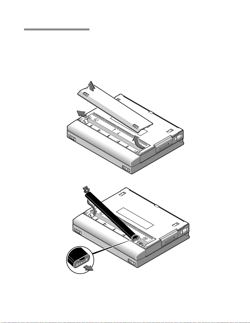
Installing the Battery
When a battery is supplied with your SPARCbook, it is packed
separately to protect the battery and SPARCbook contacts while the
system is in transit.
Figure 1-1 Installing the Battery (SPARCbook 3000 Shown)
SPARCbook Portable Workstation User Guide 1-3
Page 24

Getting Started
Installing the Battery
Install the battery as follows (refer to Figure 1-1):
1.
Turn your SPARCbook upside down.
2.
Remove the battery cover by pressing the catch with your
thumbnail towards the side of the SPARCbook. The cover
springs open slightly allowing you to lift it off.
3.
Insert the battery, ensuring correct orientation. The battery is
shaped to make this easier.
4.
Replace the cover.
Now go to “Connecting the AC Adapter” on page 1-5.
Battery Charging
ò Your SPARCbook charges the internal battery automatically when it is
connected to an AC adapter or optional car adapter. The AC adapter or car
adapter supplies power to your SPARCbook whether your SPARCbook is
operating or not.
ò The internal battery takes between 1.5 and 4 hours to charge the first
time, depending on SPARCbook model and whether it is operating or not.
ò The internal battery uses nickel metal hydride (NiMH) cells. One
characteristic of this type of cell is that it takes several full charge and
discharge cycles for them to yield their full storage capacity (to become
conditioned). Once the cells are conditioned, the charge percentage of the
battery pack is accurately indicated on the status display.
ò The internal battery provides around 45 minutes operating time from a
full charge, depending upon SPARCbook model and the power
management options in operation. See Chapter 4, “Power Management” .
1-4 SPARCbook Portable Workstation User Guide
Page 25
Connecting the AC Adapter
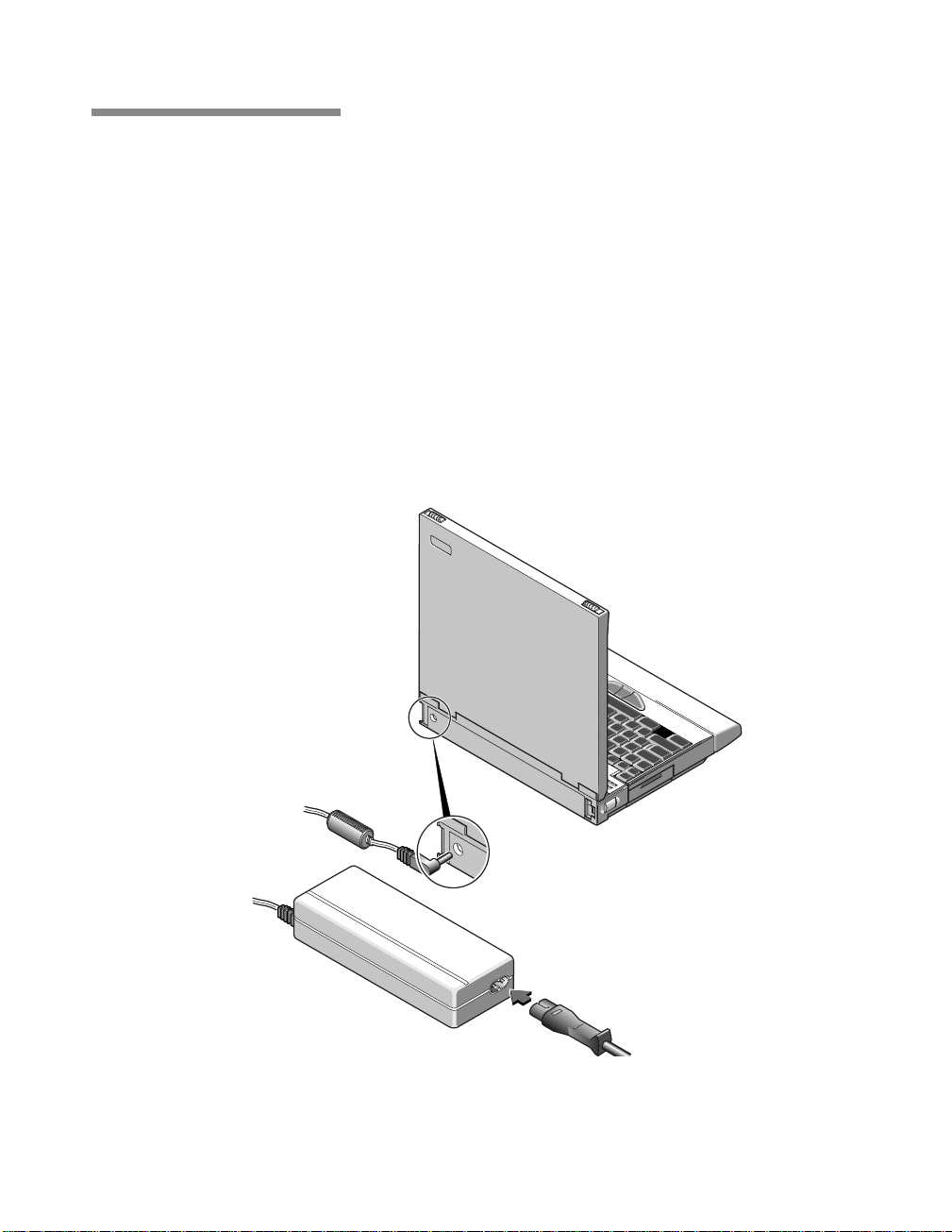
The AC adapter supplied with your SPARCbook operates at any AC
voltage in the range of 100 to 240 Volts at 50 or 60Hz. This means that
you can use the supplied AC adapter anywhere in the world where there
is a suitable supply. You may need to use different AC cords, however.
Connect the AC adapter to your SPARCbook as follows:
1.
Connect the DC cord from the AC adapter to the DC-In
connector on your SPARCbook.
2.
Connect the AC cord from the AC adapter into a wall socket or
distribution panel.
Getting Started
Connecting the AC Adapter
Figure 1-2 Connecting the AC Adapter
SPARCbook Portable Workstation User Guide 1-5
Page 26
Getting Started
Powering On for the First Time
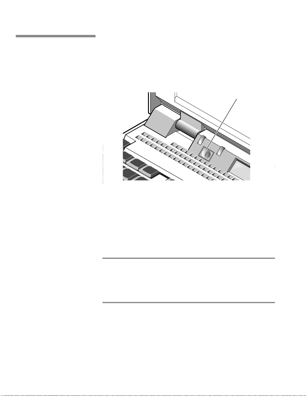
Powering On for the First Time
To power your SPARCbook on, press the Power On button, as
illustrated in Figure 1-3.
Power ON
Button
Note
Figure 1-3 Powering On
As your SPARCbook powers on, a number of codes are displayed in the
status display and then, after some delay, the system configuration
screen is displayed.
Configuring your system is described in Chapter 2, “Initial System
Configuration” .
On a new system, the Power On button is only configured to power your
SPARCbook on. It has no effect while the SPARCbook is running. However, it
can be configured as a Save button using the NCE Save and Resume panel. See
Chapter 5, “Save and Resume” in this guide and “Save and Resume Panel” in
your NCE User Guide.
1-6 SPARCbook Portable Workstation User Guide
Page 27

Powering Off
Your SPARCbook provides you with two methods of shutting down
and powering off:
• Conventional system shutdown
• Save
Powering off using a system shutdown
To shut your SPARCbook down, log in as root and enter the command:
# init 0
This takes the system down to the OpenBoot prompt and a safe state for
power-off. Power off by pressing Pause-O. The next time you power
on your SPARCbook carries out a full system startup and not a Resume.
Powering off using Save
Getting Started
Powering Off
The Save facility allows you to power off quickly without having to
perform lengthy shutdown procedures. To power off with Save, press
Pause-O on the keyboard. The built-in display, if it is in use, goes blank
and your SPARCbook system beeps before it powers off. It takes
between 30 and 90 seconds for the Save to complete.
Save and Resume
ò The Save and Resume feature makes it easy to
start and stop your SPARCbook without having to
perform the lengthy Solaris shutdown and startup
procedures of a conventional UNIX system. The
system’s complete operational state is saved onto
specially assigned partition on the hard disk and is
completely restored when you next power on. You do
not have to close applications before performing a
Save because they are completely unaffected by Save
and Resume, allowing you to take up exactly where
you left off.
4 Use Save and Resume only if your SPARCbook is
going to be used in the same way when you next
power-on.
5 Use a system shutdown and reboot if you change
or remove disks, change displays or change the
system’s network environment while it is powered
off.
Your SPARCbook provides several ways to initiate a
Save. These are described in Chapter 5, “Save and
Resume” .
SPARCbook Portable Workstation User Guide 1-7
Page 28

Getting Started
Using Full System Startup
Using Full System Startup
Your SPARCbook can be booted in the same way as any conventional
desktop SPARC workstation running Solaris.
• Use a full system startup if you have reconfigured your system’s
• Use a full system restart if, for any reason, you do not wish to use
In cases where you have previously used Save to power off or if Resume
fails, a full system startup can be carried out as follows:
1.
2.
hardware in any way while it has been powered off. Save and
Resume may fail in cases where the system hardware has been
reconfigured.
the Save and Resume facility.
If your system is powered on, press Pause-O to power off.
Press the power on button or, if your system already has power
but is failing to Resume, press Pause-R.
3.
When the OpenBoot start-up screen is displayed, press Pause-A.
4.
At the OpenBoot prompt, type in the following commands:
ok create no-resume?
ok boot
1-8 SPARCbook Portable Workstation User Guide
Tadpole S3 SPARCbook, keyboard present
ROM Rev 2.15 V1.00
32 MB memory installed, Serial #10683270
Ethernet address 0:0:83:a3:3:86, Host ID: Host ID:
80a30386
Initializing memory Type help for more information
ok
Page 29

Using Different Screen Environments
Your SPARCbook’s built-in display operates in two modes: terminal
mode and Xwindows mode. The default mode is Xwindows mode.
When your system starts up, the Solaris login window allows you to
select the display mode from the Option menu.
Session Allows you to select between the CDE or the
OpenWindows desktop environments, both of which
operate in Xwindows mode.
Command Line Login
Allows you to select the terminal mode. In this mode,
your display operates as a simple ASCII terminal and
displays the Solaris command line.
Note
If your SPARCbook starts at the command prompt, you can enter
OpenWindows by typing the command openwin.
Getting Started
Using Different Screen Environments
Starting NCE
The factory installed Solaris 2.5.1 may not have CDE installed. If you wish to use
CDE it must be installed from the supplied SunSoft CD-ROM.
The Notebook Computing Environment (NCE) provides a suite of
graphical tools that make mobile system administration easier. For
example:
• The Display Panel allows you to configure your system to
operate at different display resolutions.
• The Save and Resume Panel allows you to configure the
operation of the Save and Resume feature.
For information about using NCE, refer to your NCE User Guide.
SPARCbook Portable Workstation User Guide 1-9
Page 30

Getting Started
Using an External Keyboard and Mouse
Using an External Keyboard and Mouse
Although the built-in keyboard and pointing stick provide full
functionality, you may find it convenient when using your SPARCbook
as a desktop machine to use a Sun-compatible keyboard and mouse with
your SPARCbook.
The external keyboard and mouse interface is combined, and can be
used to connect a type 4 or 5 Sun keyboard and mouse.
Note
Your SPARCbook supports the connection of a Sun-compatible keyboard and
Sun-compatible optical or mechanical mouse. Other types of mouse or keyboard should
not be connected.
The pinout of the combined keyboard and mouse interface is standard,
allowing you to connect any Sun-compatible external mouse and
keyboard with their standard cables. The combined keyboard and
mouse interface allows you to connect an external mouse and keyboard.
The mouse can be connected directly to the SPARCbook or indirectly
via a connector provided on the external keyboard. The internal
pointing stick and keyboard remain active while an external keyboard
and mouse are connected.
Your keyboard is enabled as soon as it is connected to your
SPARCbook. You can alter the operation of your keyboard and change
the keyboard layout if you wish by using the Keyboard panel of the
Notebook Computing Environment. See “Keyboard Panel” in your
NCE User Guide.
1-10 SPARCbook Portable Workstation User Guide
Page 31

Initial System Configuration
This chapter describes how to carry out the initial system configuration of your
SPARCbook, including how to create your own user account, how to configure
an Internet Protocol (IP) address and host name, and how to set the timezone.
Your SPARCbook notebook workstation is shipped from the factory with the
Solaris operating environment ready installed for you on the removable hard
disk. However, before using your SPARCbook for the first time, configure the
operating system following the instructions in this chapter. You may require
the assistance of a system administrator to carry out the configuration or to
provide you with essential information.
This chapter contains the following sections:
• What System Configuration Entails . . . . . . . . . . . . . . . . . . . 2 - 2
• Initial Configuration – Worked Example . . . . . . . . . . . . . . . 2 - 2
• Setting up a user account . . . . . . . . . . . . . . . . . . . . . . . . . . . 2 - 5
22
2
• Restarting the System . . . . . . . . . . . . . . . . . . . . . . . . . . . . . . 2 - 7
Page 32

Initial System Configuration
What System Configuration Entails
What System Configuration Entails
Basic configuration of you SPARCbook involves the following basic
steps:
• Assigning a host name and Internet Protocol (IP) address to your
SPARCbook
• Setting your time zone
• Setting a password for the super user (root) account
• Setting up user accounts
The remainder of this chapter provides you with a worked example.
Note
The initial configuration process may differ slightly between Solaris versions so
that the order in which steps are carried out may differ from the worked
example below. As a general rule, you should carry out any steps following any
instructions displayed on the screen.
For full details of how to configure Solaris, refer the SunSoft Solaris
documentation.
Initial Configuration – Worked Example
Collecting the required system information
Before configuring your SPARCbook, assemble the information you
will require by filling in the following table. You may need to consult
your system administrator for the correct information for your system.
2-2 SPARCbook Portable Workstation User Guide
Page 33

Category Worked Example Your Configuration
Host Name chianti
IP Address 195.5.2.15
Subnet Mask 255.255.255.0
Name Service None
Name Server Hostname None
Time Zone No example given
User Name Betty Small
Table 2-1 Configuration Worksheet
Network information
Host Name
ò
The host name of your SPARCbook is the name by which it is known
to other computers connected to the network. For example:
Host name: chianti
Initial System Configuration
Initial Configuration – Worked Example
The name must be unique to your SPARCbook system as duplicated
names will disrupt the operation of the network.
ò
Internet Address
The IP address of your SPARCbook consists of four groups of decimal
numbers separated by periods. For example:
Internet (IP) Address: 195.5.2.15
The IP address must be unique to your SPARCbook system as
duplicated addresses will disrupt the network.
ò
Name Service
After you have entered your SPARCbook’s host name and IP address,
you are prompted to select the name service you require. Using NIS and
NIS+ can cause start-up problems if you later try to use your
SPARCbook without a network connection.
SPARCbook Portable Workstation User Guide 2-3
Page 34

Initial System Configuration
Initial Configuration – Worked Example
If your SPARCbook is going to be used as a mobile computer, it may
be advisable to select None from this screen and configure your
SPARCbook later to use the domain name service (DNS). See Section
“Configuring your SPARCbook to use a name server” on page 8-11.
ò
Subnets
This screen prompts you to specify whether or not your SPARCbook is
going to be attached to a subnet. Larger corporate networks are often
divided into smaller segments called subnets. If your SPARCbook is
going to be used as standalone system, enter No.
If your SPARCbook is going to be connected to a large network, you
will need to consult your system administrator for the correct choice for
this screen.
Time zone
When prompted, enter your time zone information following the
on-screen instructions.
If your time zone does not correspond with any of those listed, you can
set a time zone relative to Greenwich Mean Time (GMT), also known
as Coordinated Universal Time (CUT), or specify a timezone file to be
used.
Setting a superuser password
Enter a password for the super user (or root) account. The super user
account has special privileges and is used mainly for system
administration tasks. Inadvertent or unauthorized use of some of the
commands available to super user can damage the operating system and
render your SPARCbook unusable. For this reason you are advised to
set a password for the super user account.
The password should consist of a minimum of six characters. Any
printable characters can be used including letters, numbers and
punctuation marks.
2-4 SPARCbook Portable Workstation User Guide
Page 35

Initial System Configuration
Initial Configuration – Worked Example
After you have entered your root password, a Solaris 2 system displays
the Solaris login prompt. You should create a user account as described
in the next section.
Moving Between User and the Root Accounts
ò Many of the operations described in this guide require you to be logged
in as root. The root account gives you the privileges required to carry out
system administration tasks such as disk maintenance. However, using the
root account for day to day purposes is very risky as you can easily cause
damage to the operating system.
ò As a rule, you should log in to your normal user account for every day
purposes. Then, when you need to carry out particular task as root, enter the
su command and the root password to log in to the root account:
% su
Password:
#
ò The hash prompt (#) indicates that you have root privileges.
Setting up a user account
ò
ò When you have completed the task requiring root privilege, close the
root account by pressing
Ctrl-D on the keyboard.
Starting the User Account Manager
For day-to-day use, you should set up a user account by using the
OpenWindows admintool. This provides an easy-to-use way to create
a user account. To open an admintool window carry out the following
steps:
1.
At the Solaris prompt, log in as root and then start
OpenWindows with the following commands:
login: root
password:
# openwin
The OpenWindows desktop is displayed.
SPARCbook Portable Workstation User Guide 2-5
Page 36

Initial System Configuration
Initial Configuration – Worked Example
2.
3.
4.
5.
Move the cursor to a clear area of the desktop background and
press and hold the menu (center) mouse button. The
OpenWindows desktop menu is displayed.
From the menu, select Programs and then Command Tool.
A cmdtool window is displayed.
In the command tool window, enter the command:
# admintool
The Admintool window is displayed. If necessary, select the
User from the Browse menu to display a list of users.
From the Edit menu, select Add. The Add User window is
displayed.
2-6 SPARCbook Portable Workstation User Guide
Figure 2-1 Admintool
Page 37

Initial System Configuration
Restarting the System
ò
User Name
This is the login name of the user. This is often an abbreviation or your
initials. For example, for the user Betty Small might use betty. The
comment field is commonly used to describe the user. In this case, the
user Betty Small’s full name.
ò
User ID
The user ID is a unique number by which the network identifies a user
account. Numbers 1 through 10 are reserved. You should consult the
network administrator for your site for a valid number. If you are using
your system as a stand-alone unit, use 100 for the first account, 101 for
the next and so on.
ò
Account Security
This section is used to specify how the password for the account is to be
administered. Use this section to specify such the required change
frequency, expiration date and number of days warnings are issued
advising that the password should be changed.
ò
Restarting the System
Home Directory
This section creates a home directory for your new user account. You
must enter a directory path in the text field. User accounts are normally
located in /opt. In this example, Betty Small would enter the path
/opt/bs.
After you have entered your account details, click on OK and Solaris
creates a user account based to your specifications.
When you have completed system configuration, carry out a complete
system reboot by entering the command:
# init 0
This takes the system down to the OpenBoot prompt and a safe state for
power-off without using the Save and Resume feature. Power off by
pressing Pause-O.
Power on again by pressing the power-on button.
SPARCbook Portable Workstation User Guide 2-7
Page 38

Initial System Configuration
Restarting the System
2-8 SPARCbook Portable Workstation User Guide
Page 39

Main System Components
This chapter identifies the main components of your SPARCbook and briefly
describes the function of each. Read this chapter to familiarize yourself with
the main components.
This chapter contains the following information:
• Front Detail . . . . . . . . . . . . . . . . . . . . . . . . . . . . . . . . . . . . . . 3 - 2
• Rear Detail . . . . . . . . . . . . . . . . . . . . . . . . . . . . . . . . . . . . . . 3 - 4
• Underside Detail . . . . . . . . . . . . . . . . . . . . . . . . . . . . . . . . . . 3 - 6
• I/O Panel . . . . . . . . . . . . . . . . . . . . . . . . . . . . . . . . . . . . . . . . 3 - 7
• The Built-In Display . . . . . . . . . . . . . . . . . . . . . . . . . . . . . . . 3 - 10
• The Built-In Keyboard . . . . . . . . . . . . . . . . . . . . . . . . . . . . . 3 - 11
• The Pointing Stick . . . . . . . . . . . . . . . . . . . . . . . . . . . . . . . . 3 - 15
33
3
• Status Display . . . . . . . . . . . . . . . . . . . . . . . . . . . . . . . . . . . . 3 - 16
Page 40

Main System Components
Front Detail
Front Detail
5
The front detail of your SPARCbook 3000 is illustrated in Figure 3-1.
1
2
3
4
8
7
6
Figure 3-1 Front View of SPARCbook 3000
3-2 SPARCbook Portable Workstation User Guide
Page 41

Main System Components
Front Detail
Feature Function
(1) Latches The latches are used to open the lid of your
SPARCbook. Slide both latches towards the outer
edges of the unit to release the lid.
(2) Built-in display The built-in display, often referred to as the TFT
display, displays the system output. You can also
use an external display connected at the rear of the
unit (see “Connecting an External Display” on
page 11-8), in which case this display may be blank.
(3) Po wer ON LED The power-ON LED (green) lights when your
SPARCbook is powered on.
(4) Battery Warning
LED
(5) Po wer On
Button
The battery warning LED (orange) signals when the
charge level of the internal battery is low. See
“Power Management System Operation” on
page 4-2.
Your SPARCbook performs an automatic Save
when the battery is nearly discharged, allowing you
to Resume work when the battery has been replaced
or your system has been connected to an A C supply.
The Power On button is used to power your
SPARCbook on. On a new system, it is only
configured as a power-on button; the unit is
powered off by pressing Pause-O on the k eyboard.
See “Powering off using Save” on page 1-7.
However, the button can be configured to function
as a power off button in the NCE Save and Resume
panel.
(6) Pointing Stick
and Mouse
Buttons
(7) PCMCIA Port The PCMCIA port provides two PCMCIA slots.
(8) Status Display The status display provides low-level system status
The Pointing Stick is a built-in pointing device that
simulates a mouse. It is used in conjunction with
three buttons located at the front of the keyboard
which function as mouse buttons.
You can install up to two Type I or II devices, or one
T ype III device in your SPARCbook. See Chapter
10 “PCMCIA Interface”.
information, such as battery charge level and
interface operation. See “Status Display” on
page 3-16.
SPARCbook Portable Workstation User Guide 3-3
Page 42

Main System Components
Rear Detail
Rear Detail
1
The rear detail of your SPARCbook is illustrated in Figure 3-2.
2
3
Figure 3-2 Your SPARCbook 3000 Viewed from the Rear
3-4 SPARCbook Portable Workstation User Guide
5
4
Page 43

Main System Components
Feature Function
Rear Detail
(1) External Battery
Connector
(2) DC-In
Connector
(3) I/O Panel The I/O panel provides interface connections used
(4) External Battery
Release
(5) Removable
Hard Disk
The external battery connector is used by an
optional clip-on external battery pack to supply
power to a SPARCbook. See “Using an External
Battery Pack” on page 4-8. This option in not
available on SPARCbook 3000 models.
The DC-In connector is used to connect the AC
adapter or optional vehicle adapter to your
SPARCbook.
for connecting peripherals and for communications.
See “I/O Panel” on page 3-7.
The external battery release is used to release a
clip-on external battery pack when one is attached
to your SP ARCbook 3. Slide the release to wards the
front of your SPARCbook 3to release the battery.
The hard disk in your SPARCbook is sealed within
a removable module. The module can be removed
and replaced easily. See “Fitting and Removing the
Hard Disk” on page 6-3
SPARCbook Portable Workstation User Guide 3-5
Page 44

Main System Components
Underside Detail
Underside Detail
The underside of the SPARCbook 3000 is illustrated in Figure 3-3.
2
3
4
Figure 3-3 The Underside of Your SPARCbook 3000
1
Feature Function
(1) Legs These can be used to tilt the system for a more
(2) Machine
Identification
Label
(3) Battery Cover
Catch
(4) Battery Cover This covers the battery compartment. Before you
3-6 SPARCbook Portable Workstation User Guide
comfortable typing angle and to cool the system by
allowing air to circulate beneath the base casting.
The machine identification label contains the serial
number of your SPARCbook and information about
the machine type. This information is required to
obtain repair service.
This is used to release the battery cover.
can use your SPARCbook you need to insert the
internal battery. See “Installing the Battery” on
page 1-3
Page 45

I/O Panel
Model differences
Main System Components
I/O Panel
The I/O panel at the rear of the SPARCbook provides connectors for all
of the expansion and communications interfaces except for the
PCMCIA.
The following figures illustrate the I/O panels of the SPARCbook
models.
A B
Figure 3-4 I/O Panel, SPARCbook 3000 Models
A B
Figure 3-5 I/O Panel, SPARCbook 3 Models
SPARCbook Portable Workstation User Guide 3-7
Page 46

Main System Components
I/O Panel
Connector descriptions
The function of each connector on the I/O panel is described in the
following table.
Icon Name Description
The Ethernet interface allows connection to a wide variety of local area
Ethernet Interface
networks via an external transceiver. Using the Ethernet interface is
discussed in Chapter 8 “Using the Network Interface”.
Parallel Port
Video Port
SCSI Port
Keyboard/Mouse Port
Serial Ports A and B
The parallel port allows for the connection of devices such as printers
and scanners. See “Using Parallel Devices” on page 12-3.
The video port allows you to connect external displays. A wide variety
of displays can be driven directly from this port. Using the display
interface is discussed in Chapter 11 “Using Displays”.
The SCSI port allows you to connect external hard disks, tape drives,
and CD-ROM driv es to your SPARCbook. See Chapter 7 “Using SCSI
Devices”.
The combined keyboard and mouse port allows you to connect a
Sun-compatible keyboard and mouse. The external keyboard operates
simultaneously with the built-in keyboard. The e xternal mouse operates
simultaneously with the Pointing Stick.
See “Using Serial Devices” on page 12-2.
The serial (or TTY) ports allow the connection of devices such as serial
printers, terminals, and external modems. See “Using Serial Devices”
on page 12-2.
Headphones
Stereo headphone socket provided for personal listening. See “Using
Audio Equipment” on page 12-4.
3-8 SPARCbook Portable Workstation User Guide
Page 47

Main System Components
Icon Name Description
I/O Panel
Audio In
Audio Out
ISDN Interface
Internal Modem
(SPARCbook 3 models
only)
Note
The audio interface provides stereo line-in and line-out connections. It
allows stereo sound input from an external sound source, such as a
microphone or CD player, to be recorded and stored by your
SPARCbook and then played out to external audio equipment. See
“Using Audio Equipment” on page 12-4
The ISDN interface allows connection to the Integrated Services Digital
Network services provided by telephone companies.
The Internal modem interface is used to connect your SPARCbook’s
internal fax modem to the telephone system.
SPARCbook models with a built-in modem are approved for connection to
telephone systems in the United States of America (in accordance with FCC Part
68 rules, as written on page iv) and Canada. You are not permitted to connect
the internal modem to public telephone systems in any other country.
SPARCbook Portable Workstation User Guide 3-9
Page 48

Main System Components
The Built-In Display
The Built-In Display
The built-in display is used by your SPARCbook to display information
when an external high-resolution display is not being used. To use the
internal display, open the lid and adjust the viewing angle to suit your
needs.
Figure 3-6 Adjusting the Display Viewing Angle
3-10 SPARCbook Portable Workstation User Guide
Page 49

Viewing angle
Display brightness
The Built-In Keyboard
Main System Components
The Built-In Keyboard
To open your SPARCbook, slide the two latches on the front of the unit
outwards while simultaneously lifting the lid upwards. To obtain the
best viewing angle, adjust the position of the lid.
The display incorporates a fluorescent backlight to provide full-display
legibility under a range of lighting conditions. You can adjust the
brightness of the built-in display from the keyboard with the following
key combinations:
• Screen brightness is increased by pressing Pause-
• Screen brightness is decreased by pressing Pause-
The built-in keyboard provides full-size keys laid out in a conventional
manner. However, the number of keys provided is limited by the
compact size of the SPARCbook which means that some of keys
normally found on a full-sized keyboard must be simulated using key
combinations.
Function keys
The functions of the twelve function keys (F1 - F12) are controlled by
the operating environment and some applications. In addition the keys
emulate two further banks of function keys, normally called Left and
Right function keys, when the Alt and Ctrl keys are pressed as well.
• Pressing the Alt key positioned to the right of the space bar and
a function key provides the Left function.
• Pressing the Ctrl key positioned to the right of the space bar and
a function key provides the Right function.
SPARCbook Portable Workstation User Guide 3-11
Page 50

Main System Components
The Built-In Keyboard
The Right functions of F13, F14 and F15 are provided by pressing the
Ctrl key (positioned to the right of the space bar), plus either the
Delete, End or Page Down key respectively. For example, F14 is
emulated by pressing Ctrl-End.
Microcontroller function keys
Your SPARCbook system provides software control over a number of
special features, such as increasing or decreasing the brightness of the
TFT display. These features are controlled by a dedicated
microcontroller and several key combinations are predefined to operate
them, as shown below.
Operation Key Combination
Start Openboot (after power-on or reset) Pause-A
System reset Pause-R
System shutdown (using Save) Pause-O
Cancel Save Pause-P
Increase TFT display brightness
Pause-
Decrease TFT display brightness
Move cursor to center of display Pause-Home
Calibrate Mouse Pause-Home (hold down for
Zoom in Pause-Page Up
Zoom out Pause-Page Down
Increase volume
Decrease volume
Quit OpenWindows F1-Alt-Delete
Compose Ctrl (right of the space bar)-J
Right function keys Ctrl (right of the space bar)-Fn
Left function keys Alt (right of the space bar)-Fn
Enable/Disable numeric keypad mode Shift-NumLk
3-12 SPARCbook Portable Workstation User Guide
Pause-
3 seconds)
PausePause-
Page 51

Delete and interrupt keys
Numeric keypad
Main System Components
The Built-In Keyboard
The Solaris Operating System can be configured to use different keys
for different functions. By default, the delete key is the Del key. The
interrupt key, used to quit an application, is the Ctrl-C sequence.
Some of the keys also function as a numeric keypad. Numeric-keypad
mode can be enabled and disabled by pressing Shift-NumLk.
• Pressing Shift-NumLk enables numeric-keypad mode.
• Pressing Shift-NumLk again disables numeric-keypad mode.
The character for each key while in numeric-keypad mode is screen
printed on the top surface next to the (larger) typewriter character, as
shown in Figure 3-7.
NumLk
ScrLk
3
Pause
_
+
-
+-
=
{
[
:
"
*
;
'
>
?
.
/
/
.
Ctrl
Print
Screen
SysRq Break
F6 F7 F8 F9 F10 F11 F12 Delete End
%
^
&
5
6
7
8
7 8
Home
T Y U I O P
F G H J K L
C V B N M
*
(
)
9
9
0
PgUp
4 5
1 2
End PgUp
<
0
,
Ins Del
Alt
6
Figure 3-7 Numeric Keypad
Insert
}
]
Shift
Home
Backspace
|
\
Enter
Page
Up
Page
Down
SPARCbook Portable Workstation User Guide 3-13
Page 52

Main System Components
The Built-In Keyboard
F6 F7 F8 F9 F10 F11 F12 Delete End
NumLk
Print
ScrLk
Screen
SysRq Break
Pause
Insert
Home
Page
Up
Page
Down
%
^
5
&
6
7
7 8
Home
T Y U I O P
F G H J K L
C V B N M
Figure 3-8 Numeric Keys with Shift Pressed
While the numeric-keyboard mode is active, pressing and holding the
Shift key causes some of the keypad keys to function as cursor and
screen control keys. The character for each key, while in keypad mode
with the Shift key pressed, is printed on the key’s front surface, as
shown in Figure 3-8
Adjusting the keyboard angle
The keyboard angle is adjusted by releasing the legs on the underside of
your SPARCbook which are illustrated in Figure 3-3 on page 3-6.
*
(
9
PgUp
9
8
4 5
1 2
End PgUp
<
0
,
Ins Del
Alt
_
)
0
6
3
>
.
.
+
-
+-
=
{
[
:
"
;
'
*
?
/
/
Ctrl
}
]
ShShiifftt
Backspace
|
\
Enter
Note
Releasing the legs aids system cooling by allowing air to circulate beneath the
base casting.This ensures more reliabl operation in warmer climates.
• Release the legs by pressing them towards the outside of the
case. They pop out of their recesses into position.
• To return the legs to their storage position, press them back into
the recesses where they click into place.
3-14 SPARCbook Portable Workstation User Guide
Page 53

The Pointing Stick
Main System Components
The Pointing Stick
Your SPARCbook keyboard incorporates a Pointing Stick. This is used,
together with three buttons in front of the spacebar, to emulate a
3-button mouse.
Pointing stick
Note
Mouse keys
Figure 3-9 The Pointing Stick
The Pointing Stick can be operated with the index finger of the left or
right hand while your hands are in the normal typing position. The
Pointing Stick is pressure-sensitive and the cursor moves in the
direction in which it is pressed at a speed corresponding to the pressure
applied.
Under some operating conditions, the cursor may drift down or across the
display without the pointing stick being pressed, or may move in one direction
more effectively than it does in the other. If this happens press Pause-Home
and hold the keys down for 3 seconds. The microcontroller will recalibrate the
pointing stick.
SPARCbook Portable Workstation User Guide 3-15
Page 54

Main System Components
Status Display
Status Display
The status display, located on the front of the unit below the main
display, provides you with information about your SPARCbook
operating status. It provides two lines of sixteen characters.
The upper line is the battery status line and provides information about
the batteries. The lower line is the machine and OS status line and
provides information about interface activity, external DC supply and
operating system status.
Figure 3-10 The Status Display
Note
Battery status
Machine and OS status
The battery status line on some earlier S3 models does not show a percentage
number until the battery has been fully charged.
On a SPARCbook 3, the battery status line indicates whether you are
running on the internal battery (Int) or an external battery pack (Ext). It
also indicates the level of charge of the battery being monitored as a
percentage of a full charge. The plus sign (+) indicates that the battery
being monitored is receiving a charge from the AC adapter connected
to the DC-In connector.
The machine and OS status line displays a row of symbols to indicate
interface activity or availability.
3-16 SPARCbook Portable Workstation User Guide
Page 55

Symbol Name Meaning
DC-In Active Indicates that your SPARCbook is receiving DC
power from the external AC adapter or from a car
adapter.
WAN Active Indicates that a wide area network connection has
been established, either via the internal modem or
ISDN interface.
LAN Active Indicates that the Ethernet interface is active and
connected to a viable network.
PCMCIA Active Indicates the active presence of a PCMCIA card in
the PCMCIA port.
Main System Components
Status Display
(sequence)
Disk Activity Spinner Indicates that hard disk activity is in progress.
The three characters at the extreme right of the machine and OS status
line display a hexadecimal code to indicate the status of the operating
system software.
SPARCbook Portable Workstation User Guide 3-17
Page 56

Main System Components
Status Display
3-18 SPARCbook Portable Workstation User Guide
Page 57

Power Management
This chapter describes your SPARCbook’s power management system. It
discusses how to use internal and external batteries and a 12V car adapter.
It contains the following sections:
• Power Management System Operation . . . . . . . . . . . . . . . . 4 - 2
• The Internal Battery . . . . . . . . . . . . . . . . . . . . . . . . . . . . . . . 4 - 4
• The Internal Battery Pack Charger Unit (IBPC) . . . . . . . . . 4 - 6
• Using an External Battery Pack . . . . . . . . . . . . . . . . . . . . . . 4 - 8
• Using A 12V Car Adapter . . . . . . . . . . . . . . . . . . . . . . . . . . 4 - 12
44
4
Page 58

Power Management
Power Management System Operation
Power Management System Operation
The power management system monitors the DC-In connector, external
battery connector and the internal battery.
Battery charging
Your SPARCbook detects when it is powered from the AC adapter or
car adapter, automatically charges the battery and displays a DC symbol
in the lower line of the status display. The charging current is adjusted
according to the battery’s existing level of charge and according to
system temperature. The battery is charged at a faster rate until it is
almost fully charged, and then the system automatically switches to a
trickle charge to maintain the battery in good condition. You can use
your SPARCbook as normal while the battery is being charged.
Battery status
Battery status information is shown on the upper line of the status
display. This provides an indication of the battery’s level of charge,
expressed as a percentage, with a plus (+) sign to indicate that it
receiving a charge or with a minus sign (-) to indicate that it is being
drained. See Figure 4-1.
The power management system detects when the system is being
powered from the internal battery or from an external battery pack
(SPARCbook 3 models only). These conditions are shown in the status
display as follows:
Int. Battery
Indicates that the internal battery’s status is being
displayed.
4-2 SPARCbook Portable Workstation User Guide
Figure 4-1 The Status Display
Page 59

Battery warning LED
Power Management
Power Management System Operation
Ext. Battery
Indicates that the external battery’s status is being
displayed (only applies to SPARCbook 3 models).
When your SPARCbook unit has no external DC power connected, the
orange-colored battery warning LED provides a visual warning when
the battery is nearing exhaustion.
Battery
Warning
LED
Figure 4-2 The Battery Warning LED
The battery warning LED provides two warning levels:
• First, the LED flashes to indicate that there are 3 to 5 minutes of
battery power remaining. The LED flashes faster as this time
runs down.
• Second, the LED illuminates continuously to indicate that the
battery is almost completely discharged.
At the second warning, you can take one of the following actions:
• Connect the AC adapter or car adapter to charge the battery and
continue working.
• Connect an external battery pack and continue working
(SPARCbook 3 models only).
SPARCbook Portable Workstation User Guide 4-3
Page 60

Power Management
The Internal Battery
Maximizing battery life
The Internal Battery
• Power your SPARCbook off using Save (by pressing Pause-O),
replace the battery with an already fully charged battery and then
press the power on button to Resume where you left off.
• Save any files you may be working on and continue working
until your SPARCbook performs an automatic Save.
The Battery and Power tools provided by the Notebook Computing
Environment offer several ways for you to extend battery life, such as
reducing the screen brightness when using battery power or using a
slower CPU clock speed. For information about how to use these
facilities, see the NCE User Guide.
The internal battery is specially designed for use with your
SPARCbook. It incorporates a number of safety features.
• It is shaped to aid correct insertion.
• It contains electrical protection against damage by short circuit.
• It is physically protected against chemical leakage or rupture.
Operating on internal battery power
The internal battery typically powers your SPARCbook for around 45
minutes (or longer depending upon model and power saving options
selected). Using any of the interfaces, particularly the Ethernet and
SCSI, or an external mouse or keyboard, causes a greater drain on the
battery and may shorten this period.
4-4 SPARCbook Portable Workstation User Guide
Page 61

Replacing the internal battery
Before removing the battery, first ensure the system is powered off and
that the external power supply is disconnected. See “Installing the
Battery” on page 1-3.
Caution
Do not remove the battery while your SPARCbook is running or data files may
be corrupted and, in extreme cases, you may be unable to restart your
SPARCbook.
Battery behavior
Your computer contains a sophisticated battery management system to
ensure optimal performance from your batteries. However, for a new
system or a system that has been in storage for an extended period of
time, you should note the points below.
ò
Self Discharge
An inherent characteristic of the nickel metal hydride (NiMH) internal
battery supplied with your computer is self discharge. This causes the
battery to become exhausted after several weeks of storage even if it is
not fitted into your computer.
Power Management
The Internal Battery
Battery conditioning
Also, when it is installed in your system, the internal battery will
discharge while your computer is not in use. This may take up to 3
weeks depending on the level of charge when the system was last used.
ò
System behavior with an Exhausted Battery
The charge percentage may not be shown on the status display if the
battery is completely exhausted. However, the percentage appears when
the battery has been characterized by the battery management system
after it has been fully charged.
A new battery, or one that has not been used for a long time, will store
less charge than expected for the first few charge and discharge cycles.
This is normal. Over the course of five charge and discharge cycles, the
capacity of the battery will rise to its correct value.
SPARCbook Portable Workstation User Guide 4-5
Page 62

Power Management
The Internal Battery Pack Charger Unit (IBPC)
The Internal Battery Pack Charger Unit (IBPC)
You can recharge spare batteries using the Tadpole Series 2 Internal
Battery Charger/Storage unit (T2IBPCHRG).
Connecting the charger
Figure 4-3 Using the Battery Charger and Storage Unit
Connect your battery IBPC as follows (see Figure 4-3):
1.
Connect the AC adapter to either DC connector on the IPBC
2.
Connect the supplied DC connector cable between the remaining
DC connector on your IPBC and the DC-In socket on your
SPARCbook.
4-6 SPARCbook Portable Workstation User Guide
Page 63

Using the charger
Power Management
The Internal Battery Pack Charger Unit (IBPC)
Connecting the charger in this manner allows you to power your
SPARCbook at the same time as charging a spare battery.
To charge a battery, insert the battery, contacts first, into the battery
cavity (the battery can only be inserted into the charger one way round)
and close the charger door. Switch on the power from AC adapter.
The green LED on your charger illuminates when the AC adapter is
connected and switched on.
The amber LED on the charger illuminates constantly when the battery
is being fast charged and flashes rapidly when the battery becomes fully
charged. If the battery is too hot or too cold to charge, the amber LED
flashes slowly.
The charger keeps the battery in a fully charged state until it is removed.
The battery can be removed at any time by opening the door at the end
of the charger and withdrawing the battery.
Storing the charger’s cable
The cable supplied with the charger may be stored in the cable storage
area on the underside of the unit.
SPARCbook Portable Workstation User Guide 4-7
Page 64

Power Management
Using an External Battery Pack
Using an External Battery Pack
Note
This section applies to SPARCbook 3 models only.
To run your SPARCbook for a longer period away from an AC power
supply, you can use the optional external battery pack (available from
your SPARCbook dealer) which will power your SPARCbook for up to
6 hours of use from a single charge. The external battery pack allows
you to use all of the interfaces, an external RHDD or floppy disk drive
while away from an AC supply, although this drains the battery faster.
Identifying the main components
1
A
1 34
B
5 6 7 8
C D
2
E
9
Figure 4-4 External Battery Pack
4-8 SPARCbook Portable Workstation User Guide
Page 65

A
View
B
holder attached. Refer to views A, B and E in Figure 4-4 to identify the
following components:
1.
2.
3.
4.
5.
6.
7.
8.
9.
shows the connector side of the external battery pack, and view
shows the connector side of the external battery pack with the cord
Catch
Battery plug
DC-in connector
Extension cord holder
Release lever
Extension cord
Extension plug
Stowage for extension plug
Battery release
Attaching the external battery pack
The external battery pack can be operated with your computer in one of
two ways:
Power Management
Using an External Battery Pack
• By direct attachment to the rear of your computer.
• By connection with the extension cord.
ò
Direct Attachment
Attach the external battery pack to your computer as follows:
1.
Separate the cord holder [4] from the external battery pack by
pressing the release lever [5] and sliding the cord holder off the
external battery pack.
2.
Remove the two blanking plugs, shown in views C and D from
your computer.
3.
Attach the external battery pack to your computer by locating the
catch [2] and battery plug [3] in the corresponding receptacles on
your computer and sliding, as shown in view E.
SPARCbook Portable Workstation User Guide 4-9
Page 66

Power Management
Using an External Battery Pack
ò
Attaching the Extension Cord
It is not essential to remove the cord holder from the external battery
pack. You can also connect the battery pack as follow:
1.
Release the extension plug [6] from its stowage [7] and remove
the blanking plug, shown in view C, from your computer.
2.
Connect the extension plug by sliding it into the battery-in
socket on your computer.
Working with the external battery pack
With the external battery pack fitted, your SPARCbook operates
normaly. It can be powered from an AC supply, from the internal
battery or from the external battery pack. The Notebook Computing
Environment (NCE) software, preloaded on your computer, allows you
to specify which power source is used at any time and also which
battery (internal or external) is discharged first. This is described in the
NCE Guide User Guide.
Charging your external battery pack
To charge your external battery pack, connect the AC adapter to the
DC-in connector on the external battery pack.
Note
It is possible to plug the DC-in connector into the computer when your external
battery pack is operating on the extension cord. However, this will not charge
the external battery pack.
The external battery pack charges automatically and is charged before
the internal battery. It takes 3-4 hours to completely charge a discharged
battery. When the external battery pack is fully charged, it is kept
topped-up with a trickle charge. The battery can still be used while it is
charging, but charging takes longer.
Note
The external battery pack suspends charging if it is too hot or too cold. Charging
automatically resumes as soon as the battery returns to a suitable temperature.
4-10 SPARCbook Portable Workstation User Guide
Page 67

The charge status and condition of the external battery pack is shown on
your computer’s status display. It can also be monitored using NCE.
The main NCE window provides a graphical representation of the
charge state of both the internal and external batteries. This is described
in the NCE Guide User Guide.
Stand-alone charging
The external battery pack can be charged while it is not connected to
your computer. To do this, connect the AC adapter to the DC-in
connector of the external battery pack. The external battery pack
charges automatically.
Detaching your external battery pack
Removal of the external battery pack is a reversal of the attachment
procedure:
1.
Power your computer off.
2.
Slide the release catch on your computer [9], then slide the
external battery pack off your computer.
Power Management
Using an External Battery Pack
3.
4.
Note
If the external battery pack is being used on the extension cord, detach the cord
by sliding the extension plug out of the connector recess on your computer.
Storing the extension cord
The extension cord [6] can be stored in the cable holder [4], and the
extension plug [7] can be stored in the stowage provided [8].
Replace the two blanking plugs in your computer to protect the
battery-in contacts from damage.
If required, attach the cable holder to the external battery pack.
SPARCbook Portable Workstation User Guide 4-11
Page 68

Power Management
Using A 12V Car Adapter
Using A 12V Car Adapter
The Tadpole Series 2 12V car adapter enables you to power your
SPARCbook from a 12V vehicle cigarette lighter socket. It has power
handling capabilities similar to those of the AC adapter supplied with
your SPARCbook and enables you to power your computer with any of
the optional accessories.
Important safety information
WARNING!
DO NOT OPERATE YOUR COMPUTER WHILE YOU ARE DRIVING A
VEHICLE.
WARNING!
DISCONNECT YOUR CAR ADAPTER FROM THE VEHICLE POWER SUPPLY
BEFORE CHANGING THE INTERNAL 5A FUSE.
Connecting your car adapter
Connect your car adapter as follows (see Figure 4-5):
Caution
The car adapter is suitable for 12 volt negative earth vehicles only. Operation
under any other conditions may cause damage to your car adapter or to your
computer.
1.
Insert the large plug of your car adapter into your car’s cigarette
lighter socket.
The green LED on your car adapter illuminates when the power
from your car is connected correctly.
2.
Connect the DC cord from your car adapter to the DC-in socket
of your computer.
4-12 SPARCbook Portable Workstation User Guide
Page 69

Power Management
Using A 12V Car Adapter
Using your car adapter
Figure 4-5 Conecting the Car Adapter
Your SPARCbook can be operated normally while powered from your
car adapter. It charges the internal battery in the same way as the AC
adapter.
Your car adapter is of a high-efficiency design. However, to conserve
your vehicle’s battery life, you should disconnect the adapter from the
cigarette lighter socket when your SPARCbook is not in use.
SPARCbook Portable Workstation User Guide 4-13
Page 70

Power Management
Using A 12V Car Adapter
Disconnecting your car adapter
The car adapter can be disconnected from your computer at any time,
even while your computer is operating. However, if you do disconnect
your car adapter while your computer is running, observe the following:
• Disconnect at the DC-in connector before disconnecting from
the cigarette lighter socket.
• Ensure that your computer has an internal battery installed.
Operation during engine starts
Voltage variations and spikes from your vehicle’s power supply during
engine starts can disrupt the operation of your SPARCbook. As a
precaution, disconnect your car adapter from your SPARCbook before
starting the engine, following the instructions in the previous section,
and reconnect once the vehicle’s engine is running.
4-14 SPARCbook Portable Workstation User Guide
Page 71

Save and Resume
This chapter discusses how to use Save and Resume. The Save and Resume
feature provides an easy way to start and stop your SPARCbook without
having to perform lengthy shutdown and startup procedures.
This chapter the following sections:
• How Save and Resume Functions . . . . . . . . . . . . . . . . . . . . 5 - 2
• Powering Off Using Save . . . . . . . . . . . . . . . . . . . . . . . . . . . 5 - 3
• Automatic Save Features . . . . . . . . . . . . . . . . . . . . . . . . . . . 5 - 5
• Sleep mode . . . . . . . . . . . . . . . . . . . . . . . . . . . . . . . . . . . . . . 5 - 5
• Save and Resume and Security . . . . . . . . . . . . . . . . . . . . . . . 5 - 6
• Enabling and Disabling Save and Resume . . . . . . . . . . . . . . 5 - 7
55
5
Page 72

Save and Resume
How Save and Resume Functions
How Save and Resume Functions
The operation of Save and Resume can be summarized as follows:
ò
Save
• Your SPARCbook copies the contents of the system’s DRAM
and system operating parameters onto the save partition on the
boot disk.
• An OpenBoot status flag is set that causes your SPARCbook to
look for valid Save data on the disk when you next power on.
ò
Resume
• If the OpenBoot save flag is set when you power on, your
SPARCbook attempts to read any stored information in the save
partition. If it finds valid Save data, it Resumes to exactly the
same state in operation when the Save was initiated for that disk.
If there is no valid save data available, your SPARCbook carries
out a conventional Solaris system startup.
ò A partition is reserved on your SPARCbook’s boot disk to support the
Save and Resume feature. The Save partition’s size is equivalent to the
main memory capacity of your SPARCbook. For example, if you have a
SPARCbook with 64MB of main memory (DRAM) your SPARCbook
reserves a Save partition of 64MB. See “Boot Disk Partitions” on page 6-5.
ò SPARCbook only stores Save information to the save partition on the
boot disk. It does not store this information anywhere else.
ò Because your SPARCbook Resumes from the Save partition on the boot
disk, your SPARCbook will Resume to a different session if you boot a
different disk.
ò Unexpected operations may occur if you try to Resume with a disk Saved
on a SPARCbook with a different hardware configuration, such as larger
main memory.
5-2 SPARCbook Portable Workstation User Guide
The Save Partition
Page 73

Powering Off Using Save
You can initiate a Save in several ways:
• By pressing Pause-O on the keyboard.
• By selecting Save Now in the NCE Save panel.
• By selecting Save at the top of the main NCE window.
• By selecting Save from the OpenWindows desktop Utilities
• By typing save at the Solaris root prompt.
• By closing the lid ( SPARCbook 3 models only).
The lid closed function can be enabled or disabled via the Save and
Resume panel of the Notebook Computing Environment. See “Save and
Resume Panel” in your NCE User Guide.
You do not have to close applications because they remain completely
unaffected by Save and Resume, allowing you to take up work exactly
where you left off.
Save and Resume
Powering Off Using Save
menu.
How to ensure Save and Resume operates successfully
Your SPARCbook Resumes most reliably if the hardware facilities are
the same before and after the Save is performed.
To ensure the Save and Resume facility operates correctly, it is
important that you avoid making hardware configuration changes while
your system is powered off. This applies particularly to hard disks, tape
drives, CD-ROMs and PCMCIA memory cards that are mounted as part
of your file system, and to network connections that may change.
Your SPARCbook cannot Resume successfully to a file tree that is no
longer there. To prevent problems, observe the following precautions:
• Always unmount file systems on external drives that are likely
to be disconnected before you power on again.
SPARCbook Portable Workstation User Guide 5-3
Page 74

Save and Resume
Powering Off Using Save
In many instances, your SPARCbook will recover from these situations
but this cannot always be guaranteed.
What to do if Resume Fails
If your system fails to Resume, carry out a full system reboot with the
following procedure:
1.
2.
3.
• Always unmount network file systems if your SPARCbook’s
network connection is likely to change before you power on
again.
• Always disable an external display and switch to the internal
display if you intend to change displays before you power-on
again.
Power off again, if necessary, by pressing Pause-O.
Press the power on button.
When the OpenBoot greeting is displayed, press Pause-A. The
OpenBoot ok prompt is displayed.
4.
Enter the following commands:
ok create no-resume?
ok boot disk
Your SPARCbook carries out a full system boot.
5-4 SPARCbook Portable Workstation User Guide
Page 75

Automatic Save Features
There are two automatic Save mechanisms which you can enable or
disable through the Notebook Computing Environment. These are:
Save on battery low
When the power management software on your SPARCbook detects
that the battery is low, it is able to initiate an automatic Save. You can
choose whether the Save occurs after the first or second warning, or you
can disable the Save on low battery function altogether. See “Save and
Resume Panel” in your NCE User Guide.
Save on system inactivity
When your SPARCbook is unused for a specified period (that is, there
is no mouse, keyboard or interface activity), it is able to perform an
automatic Save. See “Power Manager Panel” in your NCE User Guide.
Save and Resume
Automatic Save Features
Sleep mode
In addition to the Save and Resume feature, your SPARCbook provides
a Sleep mode. The Sleep mode can be enabled via the Notebook
Computing Environment. See “Save and Resume Panel” in your NCE
User Guide.
Sleep saves the current state of your SPARCbook to the hard disk,and
turns off the display and I/O devices. Unlike Save, however, Sleep does
not power your SPARCbook off completely but reduces the level of
battery consumption during periods of inactivity. Your SPARCbook
returns to operation instantly when any key is pressed. Sleep is initiated
automatically by the period of inactivity you have specified. See
“Power Manager Panel” in your NCE User Guide.
SPARCbook Portable Workstation User Guide 5-5
Page 76

Save and Resume
Save and Resume and Security
Your SPARCbook can be moved while in the Sleep mode and operates
for typically 5 hours from a fully charged internal battery. If the battery
nears discharge while it is in the Sleep mode, your SPARCbook
performs a Save on low battery as described in the previous section.
Save and Resume and Security
The Save and Resume feature makes your SPARCbook vulnerable to
unauthorized use. This is because Resume will take the system back
into your last desktop session, effectively bypassing the normal login
prompts.
One way to protect your SPARCbook against unauthorized use is to
remove the hard disk while it is without power. Refit it again when you
next wish to use your SPARCbook, before you power on.
If this level of protection is not sufficient, you have the following
options:
• Power off using a conventional Solaris system shutdown. To do
this, log in as root and enter the init 0 command.
This takes the system down to the OpenBoot prompt and a safe
state for power-off. Power off by pressing Pause-O. The next
time you power on your SPARCbook carries out a full system
startup and not a Resume. See “Using Full System Startup” on
page 1-8
• Disable Save and Resume altogether, see below.
5-6 SPARCbook Portable Workstation User Guide
Page 77

Enabling and Disabling Save and Resume
Enabling and Disabling Save and Resume
Although the Save and Resume feature provides an extremely
convenient method of powering down and powering on again, it does
present two drawbacks.
• It may compromise the security of the system, as described
above.
• It requires the existence of the save partition on the boot disk
which is the same size as the system’s main memory. For
example, a SPARCbook with 128MB of main memory requires
a 128MB save partition. See “Boot Disk Partitions” on
page 6-5.
If either of these issues poses a serious problem, the Save and Resume
facility can be disabled. Save and Resume can be disabled with a
reversible command, as described below, or can be disabled
permanently by assigning the save partition for general data storage.
Save and Resume
ò
Note
Disabling Save and Resume
To disable Save and Resume, enter the following command:
# saveresume -n
SAVE Partition was /dev/rdsk/c0t0d0s4
This example shows the save partition for a SPARCbook 3000 model. For a
SPARCbook 3 the save partition is /dev/rdsk/c0t3d0s4. Make a note of
the correct partition to use if you intend to re-enable Save and Resume later. See
“Boot Disk Partitions” on page 6-5.
This command disables the Save commands (such as Pause-O) and
unmounts the save partition. To power the system down, you can use
the normal Solaris shutdown commands. For example:
# shutdown -i0
When the ok (OpenBoot) prompt is displayed, press Pause-O to power
off. Restart the system in the conventional way for a desktop Solaris
system.
SPARCbook Portable Workstation User Guide 5-7
Page 78

Save and Resume
Enabling and Disabling Save and Resume
ò
Enabling Save and Resume
To enable Save and Resume, enter the following command:
Note
This example shows the save partition for a SPARCbook 3000 model. For a
SPARCbook 3 the save partition is /dev/rdsk/c0t3d0s4. The save
partition is created when the Operating System is installed from the Tadpole
distribution CD.
# saveresume -y /dev/rdsk/c0t0d0s4
# saveresume
SAVE Partition is /dev/rdsk/c0t0d0s4
5-8 SPARCbook Portable Workstation User Guide
Page 79

Using the Removable Hard Disk
This chapter discusses how to use your SPARCbook’s removable hard disk
drive (RHDD). It describes how to fit and remove the drive, how to use
additional hard disks and how to ensure a basic level of security for your
RHDD.
It contains the following sections:
• Overview . . . . . . . . . . . . . . . . . . . . . . . . . . . . . . . . . . . . . . . 6 - 2
• Fitting and Removing the Hard Disk . . . . . . . . . . . . . . . . . . 6 - 3
• Caring for Removable Hard Disks . . . . . . . . . . . . . . . . . . . . 6 - 4
• Boot Disk Partitions . . . . . . . . . . . . . . . . . . . . . . . . . . . . . . . 6 - 5
• Using Additional Removable Hard Disks . . . . . . . . . . . . . . 6 - 7
• Using a Removable Hard Disk Drive Adapter . . . . . . . . . . . 6 - 9
• RHDD Security . . . . . . . . . . . . . . . . . . . . . . . . . . . . . . . . . . 6 - 12
66
6
Page 80

Using the Removable Hard Disk
Overview
Overview
Your SPARCbook’s hard disk can be removed easily when your system
is not in use and can be stored or carried separately. The removable hard
disk provides you with effective data security for your SPARCbook
when it is not in use and allows you to upgrade your hard disk very
easily as larger capacity disk drives become available.
It is possible for you to have several boot disks for several different
projects, or for different people who share a SPARCbook workstation
to each have their own boot disk.
For example, you may have a disk for use in your office and another
disk for use at home. Each could be stored securely when not in use and
each could contain the appropriate operating system configuration for
its designated location, with networking setup on your office disk and
dial-up client services set up on your home disk.
Note
Using the Save and Resume feature, each disk can store a different
machine state that your SPARCbook Resumes when you next power on.
This means, for example, that when you power on with your home disk
fitted, your SPARCbook Resumes to the state Saved onto your home
disk.
Your SPARCbook only stores Save data onto the save partiton on your hard
disk. When you initiate a Save, an OpenBoot flag is set in your SPARCbook’s
NVRAM that causes it to look for valid Save data on the disk when you next
power up.
6-2 SPARCbook Portable Workstation User Guide
Page 81

Fitting and Removing the Hard Disk
Your SPARCbook is shipped from the factory with the hard disk
already fitted and ready for you to use. The disk can be removed as
follows:
Caution
Ensure that your SPARCbook is powered OFF before removing the hard disk.
Removing the hard disk while your SPARCbook is running may damage the
disk and destroy important data.
1.
Place your SPARCbook on a firm surface, such as a desk, with
its left side tilted upwards slightly.
2.
Slide the hard disk’s catch downwards, as shown in Figure 6-1.
3.
Pull on the catch to remove the disk from your SPARCbook.
Using the Removable Hard Disk
Fitting and Removing the Hard Disk
Catch / Cover
Figure 6-1 Removing the Hard Disk
SPARCbook Portable Workstation User Guide 6-3
Page 82

Using the Removable Hard Disk
Caring for Removable Hard Disks
Caring for Removable Hard Disks
The removable hard disk is designed to be robust but should be handled
with care. Follow these precautions in its use.
• Physical shock and vibration
Protect the hard disk from knocks and excessive vibration. You
should never remove the hard disk while your SPARCbook is
running; always power off first.
• Condensation
If your hard disk is carried separately from your SPARCbook
and is subjected to much lower temperatures, bringing it into a
warm room may cause condensation. This will not cause
damage, but you should allow your hard disk time to acclimatize
before using it.
• Static electricity
In common with most electronic components, the removable
hard disk is prone to damage due to static electric shock. To
prevent such damage, avoid touching any electrical contacts on
the hard disk.
6-4 SPARCbook Portable Workstation User Guide
Page 83

Boot Disk Partitions
Using the Removable Hard Disk
Boot Disk Partitions
The hard disk supplied with your SPARCbook is preloaded to order
with the Solaris 2 operating system; the version is dependent upon
availability and customer order. The removable disk is preconfigured as
a boot disk and is “factory” partitioned as shown in Table 6-1.
Partition
Mount Point Approx. Size (MB)
SPARCbook 3 SPARCbook 3000
dsk/c0t3d0s0 dsk/c0t0d0s0 / 25
dsk/c0t3d0s1 dsk/c0t0d0s1 swap >= DRAM
dsk/c0t3d0s2 dsk/c0t0d0s2 All disk
dsk/c0t3d0s3 dsk/c0t0d0s3 /var 72-96
dsk/c0t3d0s4 dsk/c0t0d0s4 save Same size as DRAM
dsk/c0t3d0s5 dsk/c0t0d0s5 /opt Remainder of disk
dsk/c0t3d0s6 dsk/c0t0d0s6 /usr 120
Table 6-1 Removable Hard Disk Drive Factory Configured Partitions
Note
The partition map may differ if the hard disk has been reloaded with the Solaris
operating system from the supplied CD-ROM. See “Re-installing the Operating
System from CD-ROM” on page 14-8.
The save partition is essential to support your SPARCbook’s Save and
Resume feature (see Chapter 5, “Save and Resume”) and must be the
same size as the memory capacity of your SPARCbook.
The swap partition is used by the operating system to store applications
that are running in the background. Its size, therefore, is affected by the
size of the main memory of your SPARCbook.
Model differences
The SPARCbook 3 and SPARCbook 3000 models use different types
of removable hard disks, which is why different device files are used by
default for the two model ranges.
SPARCbook Portable Workstation User Guide 6-5
Page 84

Using the Removable Hard Disk
Boot Disk Partitions
SPARCbook 3 models use a SCSI removable hard disk drive which is
labeled “Series 2” and has switches that set the target ID. SPARCbook
3000 models use an IDE removable hard disk drive which is labeled
“IDE” and has no switches. The two types have different connectors so
that it is not possible to connect the wrong type of drive to the wrong
SPARCbook model.
ò
SPARCbook 3
The SPARCbook 3 Series use a removable SCSI hard disk with a
switchable SCSI target ID, which is factory set to 3. This means that
device files for the disk slices are at /dev/c0t3d0sn, as shown in
Table 6-1. A different SCSI ID can be used for the boot disk, if required.
For example, if the disk ID were set to 0 and partitioned as shown in the
table, then the device files would be at /dev/c0t0d0sn.
ò
SPARCbook 3000
The SPARCbook 3000 Series use a removable IDE hard disk drive
which has a fixed ID. The factory installed operating system assigns this
drive as target 0 with the result that the device files for the disk slices
appear at /dev/rdsk/c0t0d0sn as shown in Table 6-1.
Main Memory Upgrades and Disk Partitions
é The sizes of save and swap partitions on the boot disk are related to the
main memory capacity of your SPARCbook.
é The main memory is provided by two single in-line memory modules
(SIMMs) which are accessible through the battery compartment. This
makes it easy for the end user to perform memory upgrades without using
special tools or equipment. However, if the capacity of the main memory is
increased then the disk’s partition map must be changed to increase the
sizes of the swap and save partitions. See “Upgrading the Main Memory”
on page 15-3.
6-6 SPARCbook Portable Workstation User Guide
Page 85

Using Additional Removable Hard Disks
Additional removable hard disks are available from your SPARCbook
supplier. These can be supplied preloaded with the Solaris operating
system for use as an alternative boot disk, or can be supplied blank for
use as additional data storage in conjunction with a removable hard disk
drive adapter (RHDDA). See “Using a Removable Hard Disk Drive
Adapter” on page 6-9.
Each new hard disk must be configured for your SPARCbook when it
is first used. This involves:
• Setting the SCSI ID for the RHDD
• Carrying out disk configuration
Note
You can only use SCSI removable hard disk drives with SPARCbook 3000
models if they are installed in a removable hard disk drive adapter. See “Using
a Removable Hard Disk Drive Adapter” on page 6-9.
Using the Removable Hard Disk
Using Additional Removable Hard Disks
ò
Setting the SCSI ID for the RHDD
Before you use the RHDD, you should check and, if necessary, set its
SCSI ID. The SCSI ID is set with three switches located on the rear of
the Series 2 RHDD as illustrated in Figure 6-2.
1
0
SCSI 2 (most significant bit)
SCSI 1
SCSI 0
Example shows binary 001 = ID1
Figure 6-2 The SCSI ID Switch (Series 2 Drives only)
The three switches on the rear of the Series 2 RHDD are binary coded
as shown in Table 6-2.
SPARCbook Portable Workstation User Guide 6-7
Page 86

Using the Removable Hard Disk
Using Additional Removable Hard Disks
Configuring a boot disk
Switch
Setting
a. It is recommended that you reserve ID3 for the boot disk in SPARCbook 3
models.
b. Do not use ID7, this is permanently assigned to the SPARCbook itself.
Selected ID
0
1 5
2 6
a
3
Table 6-2 SCSI ID Switch Settings
Switch
Setting
Selected ID
4
b
7
This procedure can be used for an RHDD that has been preloaded with
Solaris 2 operating system. The SPARCbook uses the shell script
/Factory-config to configure an RHDD as a boot disk. This creates
the disk partitions described in Table 6-1 optimized for your
SPARCbook’s memory capacity.
Configure a boot disk as follows:
1.
Ensure that your SPARCbook is powered off and fit your new
RHDD.
2.
Press the power on button.
3.
When the OpenBoot greeting is displayed, press Pause-A. Your
SPARCbook displays the OpenBoot monitor prompt.
4.
At the OpenBoot prompt, type the following command:
ok boot disk:h
5.
Your SPARCbook boots to single user mode and displays the #
prompt. Enter the following command:
# /Factory-config
6.
Press the Return key for the process to begin and follow the
displayed instructions.
6-8 SPARCbook Portable Workstation User Guide
Page 87

Using the Removable Hard Disk
Using a Removable Hard Disk Drive Adapter
Configuring a hard disk for additional storage
The procedure for doing this is described in “Configuring an External
Hard Disk – Worked Example” on page 7-6.
Using a Removable Hard Disk Drive Adapter
The removable hard disk drive adapter (RHDDA) can be used to
connect an additional Series 2 removable hard disk drives to the SCSI
port of your SPARCbook. The RHDDA is connected to the SCSI port
on the I/O panel of your SPARCbook and draws power from the
SPARCbook’s SCSI port. It does not require a separate power supply.
Note
Only Series 2 removable hard disk drives can be used with the RHDDA. The
removable hard disk drive supplied with SPARCbook 3000 models is a different
type and can only be used internally.
ò
Connecting the RHDDA
Connect the RHDDA to your SPARCbook as follows:
1.
Ensure your SPARCbook is powered off.
2.
Connect the RHDDA to the SCSI port on your SPARCbook
using the cable supplied with the RHDDA.
3.
If necessary, use the remaining SCSI connector on the rear of the
RHDDA to connect to other SCSI devices. Because it takes
power from the SPARCbook, the RHDDA should be connected
nearest to the SPARCbook.
4.
Install and configure an RHDD as described below.
SPARCbook Portable Workstation User Guide 6-9
Page 88

Using the Removable Hard Disk
Using a Removable Hard Disk Drive Adapter
ò
Inserting an RHDD
1.
Before inserting the drive, set the drive’s SCSI ID, as described
in “Setting the SCSI ID for the RHDD” on page 6-7. The
RHDDA does not have a SCSI ID of its own but takes its ID
from the RHDD installed in it.
ON
1 2 3 4
Figure 6-3 Connecting an RHDDA
2.
Slide the drive’s integral catch/cover downwards; see Figure
6-4.
3.
Tilt the front of the RHDDA upwards slightly and slide the drive
into place until you feel the connectors engage.
4.
Slide the drive’s catch/cover upwards to lock the drive in place.
5.
Configure the drive as described in “Using Additional
Removable Hard Disks” on page 6-7.
6-10 SPARCbook Portable Workstation User Guide
Page 89

Using the Removable Hard Disk
Using a Removable Hard Disk Drive Adapter
ò
Removing an RHDD
Before removing the RHDD from an adapter, ensure that there are no
disk operations in progress and unmount any file systems on the drive.
Catch/Cover
Figure 6-4 Removing an RHDD From an Adapter
Remove the drive by sliding the catch/cover downwards and sliding the
drive out of the adapter.
ò
Setting the SCSI Terminator
The RHDDA contains a switchable terminator. The terminator must be
active if the RHDDA is the only SCSI device connected to the
SPARCbook.
SPARCbook Portable Workstation User Guide 6-11
Page 90
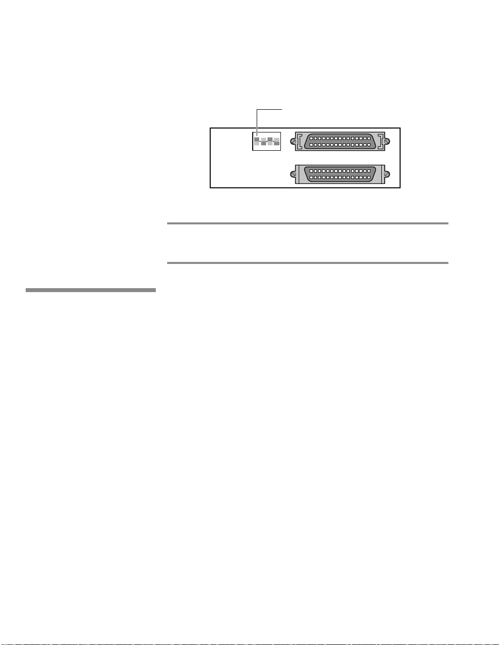
Using the Removable Hard Disk
RHDD Security
The terminator is set by setting the terminator switch, shown in Figure
6-5, to the down position. The other three switches have no function.
Note
Correctly set SCSI terminators are essential to the reliable operation of devices
connected via SCSI chain. See “SCSI Terminators” on page 7-4.
Terminator Switch (Down=ON)
1 2 3 4
Figure 6-5 The RHDDA Terminator Switch
RHDD Security
The RHDD provides your system a basic level of security by allowing
you to remove it from your SPARCbook when it is not in use and
storing it separately. However, it is equally possible for the RHDD to be
removed by an unauthorized person. The RHDD can be removed and
installed into a similar SPARCbook allowing your files and
applications to be accessed.
Unauthorized access can be prevented by using the Security panel
provided by NCE. This allows you to specify the serial numbers of up
to six SPARCbooks that are permitted to access your RHDD. Any other
systems are denied access.
For details about using the NCE Security panel, see the NCE User
Guide.
6-12 SPARCbook Portable Workstation User Guide
Page 91

Using SCSI Devices
This chapter describes how to connect and use external SCSI devices. It
describes how to set the SCSI ID and termination correctly and provides an
example of how to configure an external hard disk.
It provides the following information:
• Overview . . . . . . . . . . . . . . . . . . . . . . . . . . . . . . . . . . . . . . . 7 - 2
• Connecting SCSI Devices . . . . . . . . . . . . . . . . . . . . . . . . . . 7 - 3
• SCSI Terminators . . . . . . . . . . . . . . . . . . . . . . . . . . . . . . . . . 7 - 4
• SCSI IDs . . . . . . . . . . . . . . . . . . . . . . . . . . . . . . . . . . . . . . . . 7 - 4
• Configuring an External Hard Disk – Worked Example . . . 7 - 6
• Using a Tadpole SCSI Floppy Disk Drive . . . . . . . . . . . . . . 7 - 11
77
7
Page 92

Using SCSI Devices
Overview
Overview
Your SPARCbook provides a single-ended small computer system
interface (SCSI) via the I/O panel at the rear of the unit. An
industry-standard 50-pin high density SCSI-2 connector is provided.
See “I/O Panel” on page 3-7.
How to Ensure Reliable SCSI Operation
ò To ensure reliable operation of SCSI devices with your SPARCbook,
always follow these hints:
7 Do not connect too many devices to your SPARCbook.
You can connect six external devices to SPARCbook 3 models or seven to
SPARCbook 3000 models.
7 Do not exceed the maximum recommended SCSI cable lengths. See the
documentation for your SCSI devices.
4 Select a different SCSI ID (or target ID) for each device on the chain.
The default SCSI ID of the removable hard disk supplied in SPARCbook 3
models is ID3.
4 Ensure that the SCSI chain is correctly terminated. The chain must be
terminated at each physical end, but there must be no other terminators in
the chain.
4 Always connect your SPARCbook at one ph ysical end of the SCSI chain
because your SPARCbook has permanently fixed terminators.
4 Power on the SCSI devices before powering on your SPARCbook.
7-2 SPARCbook Portable Workstation User Guide
Page 93

Connecting SCSI Devices
SCSI devices are connected to the SPARCbook in a daisy chain
arrangement, as illustrated in Figure 7-1.
SPARCbook SCSI Device SCSI Device
Maximum number of devices supported
A SCSI chain supports up to eight devices connected along its length.
The SPARCbook itself counts as one device and the internal hard disk
of SPARCbook 3 models counts as another. This means that up to six
external SCSI devices can be connected to SPARCbook 3 models, and
up to seven external devices can be connected to SPARCbook 3000
models (which have an IDE internal hard disk).
Using SCSI Devices
Connecting SCSI Devices
Plug-in
Terminator
Figure 7-1 A SCSI Daisy Chain
SPARCbook positioning
Some SCSI devices provide two connectors so that they can be located
in any position along the chain. The SPARCbook has only one
connector because it should be located at the end of the chain.
SPARCbook Portable Workstation User Guide 7-3
Page 94

Using SCSI Devices
SCSI Terminators
SCSI Terminators
Note
To ensure reliable operation of your SPARCbook and external SCSI
devices, you must use an active terminator at the end of the SCSI chain.
The SPARCbook unit contains permanently fixed terminators and
should, therefore, be positioned at one end of the SCSI chain while the
device at the far end of the chain will need terminators fitted or enabled.
Some SCSI devices, such as the Tadpole Removable Hard Disk Adapter
(RHDDA), contain built-in switchable terminators (see “Setting the
SCSI Terminator” on page 6-11) which can be enabled or disabled as
appropriate. Where this is not the case, you can obtain plug-in
terminators that can be installed on the vacant connector on the device
at the end of the chain, as illustrated in Figure 7-1.
A SCSI terminator is a type of resistor network which prevents interference occurring
between conductors within the interconnecting cables, and so improve reliability.
However, terminators must not be fitted to other devices in the chain as this will cause
unreliable operation.
SCSI IDs
To allow data on individual drives to be accessed, each device
connected to the chain must have a unique address, or SCSI target ID.
A device’s target ID is not related to its physical position within the
daisy chain. IDs are usually assigned in keeping to operating system
convention to devices according to type. For example, under Solaris
2.x, a CD-ROM is assigned to SCSI ID 6 and the SPARCbook system
is assigned to ID 7.
Note
The boot disks in the SPARCbook 3 and SPARCbook 3000 models are of different types
and therefore have different identities. The SPARCbook 3’s removable hard disk is a
SCSI disk and the SPARCbook 3000’s hard disk is an IDE device.
7-4 SPARCbook Portable Workstation User Guide
Page 95

SCSI ID
0
1
2
3
Every drive has one or more special files associated with it, according
to its type function. For example, a hard disk has a block data file and
raw data file associated with each partition in the form:
/dev/dsk/c0t2d0sn block data special file
/dev/rdsk/c0t2d0sn raw data special file
Table 7-1 summarizes the assignment of drive IDs for Solaris 2.x on
SPARCbook 3 and SPARCbook 3000 models and the special files
associated with those IDs.
Special Files
SPARCbook 3 SPARCbook 3000
/dev/c0t0d0s[0-7] /dev/c4t0d0s[0-7]
/dev/c0t1d0s[0-7] /dev/c4t1d0s[0-7]
/dev/c0t2d0s[0-7] /dev/c4t2d0s[0-7]
/dev/c0t3d0s[0-7] /dev/c4t3d0s[0-7]
Using SCSI Devices
SCSI IDs
Function
External Hard Disk Drive
External Hard Disk Drive
External Hard Disk Drive
SPARCbook 3: Removable Hard Disk Drive
(with root partition)
SPARCbook 3000: External Hard Disk Drive
/dev/c0t4d0s[0-7] /dev/c4t4d0s[0-7]
4
5
/dev/c0t6d0s[0-7] /dev/c4t6d0s[0-7]
6
7 - System Unit
/dev/diskette
/dev/rmt/0
Table 7-1 SCSI Device Assignments
Exrernal Hard Disk Drive/Second CD-ROM
Drive
Tadpole External Floppy Disk Drive
Tape Drive
First CD-ROM Drive
SPARCbook Portable Workstation User Guide 7-5
Page 96

Using SCSI Devices
Configuring an External Hard Disk – Worked Example
Configuring an External Hard Disk – Worked Example
The basic procedure for installing an external hard disk drive with a
SPARCbook is as follows:
• Connect the drive with termination and SCSI ID correctly set.
• Power the system up and enter a command so that the necessary
special files are created.
• Format (if necessary) and partition the hard disk.
• Create and check a file system on each disk partition (or slice).
• Create a mount point and mount the filesystem(s).
These steps are described in a worked example below. The example
uses a preformatted drive with a SCSI ID of 2 which is connected to the
SCSI port of the SPARCbook. The disk has one partition.
ò
Connecting the drive
The SCSI ID for a hard disk can be set to 0 (zero), 1 or 2 (see Table 7-1).
The removable hard disk on SPARCbook 3 models has its ID set to 3
by default so this ID should not normally be used for an external drive.
If the external drive is the only external device or if it is connected to
the end of the SCSI chain, it should have the terminator enabled.
ò
Creating special files – boot time
Before filesystems can be created on the new hard disk, special files for
the new partitions must exist. To create the special files during the boot
process the following procedure is used:
1.
Press the power on button.
2.
When the OpenBoot start-up screen is displayed, press Pause-A.
7-6 SPARCbook Portable Workstation User Guide
Page 97

Using SCSI Devices
Configuring an External Hard Disk – Worked Example
Tadpole S3 SPARCbook, keyboard present
ROM Rev 2.15 V1.00
32 MB memory installed, Serial #10683270
Ethernet address 0:0:83:a3:3:86, Host ID: Host ID:
80a30386
Initializing memory Type help for more information
ok
3.
Enter the following command:
ok create no-resume?
ok boot -r
The -r option causes the SPARCbook to carry out hardware
reconfiguration. In this example, the SPARCbook detects the external
hard disk and creates the necessary special files to allow the
filesystem(s) on the new hard disk to be accessed.
The SPARCbook creates both block and raw device files in the
/dev/dsk and /dev/rdsk directories, respectively, for each of eight
possible slices (partitions). Thus, in the case of the example drive with
a SCSI ID of 2, the following special files are created:
Note
/dev/dsk/c0t2d0sn
/dev/rdsk/c0t2d0sn
Where:
c0 defines the SPARCbook system’s internal SCSI controller, in
this case 0 (zero). In the case of a SPARCbook 3000, this would
be 1.
t2 defines the SCSI target address, in this case 2.
d0 defines the drive number, which is normally 0 (zero) in the case
of a drive with an embedded SCSI controller.
sn defines the disk slice, where n is a number between 0 and 7.
Historically the target ID identified a SCSI controller card to which there might be
connected one or more disk drives or tape drives. The current tendency is for drives to
have a built-in (or embedded) SCSI controller in which case the drive ID is most often 0
(zero).
SPARCbook Portable Workstation User Guide 7-7
Page 98

Using SCSI Devices
Configuring an External Hard Disk – Worked Example
ò
Creating special files – on a live system
It may be necessary to add an external disk drive to a SPARCbook
without powering the system down in order to allow uninterrupted
access to available SPARCbook filesystems.
In this case, the block and raw device files, described above, can be
created as follows:
1.
Become superuser
2.
Enter the following commands:
# drvconfig -i sd
# disks
ò
Creating disk partitions
The next step is to create the required disk partitions (or slices). The disk
can be organized into up to eight partitions numbered 0 to 7. In this
example, one partition is created on slice 2, which occupies the entire
disk.
The disk is partitioned as follows:
1.
Become superuser
2.
Enter the following command:
# format
Searching for disks...done
AVAILABLE DISK SELECTIONS:
0. c0t2d0 <IBM-DVAS-2810 cyl 6183 alt 2 hd 8 sec 32>
/iommu@0,
10000000/sbsus@10001000/espdma@8400000/esp@4,88000000/sd@2,0
1. c0t3d0 <TOSHIBA-MK2428FB cyl 4000 alt 2 hd 8 sec 32>
/iommu@0,
10000000/sbsus@10001000/espdma@8400000/esp@4,88000000/sd@2,0
Specify a disk (enter its number): 0
The information displayed for the disks will vary from system to system
but should provide information about the drive vendor, drive model and
drive characteristics. In this example, a note is made of the number of
cylinders that the new drive has, in this case 6183, which is required for
disk partitioning.
7-8 SPARCbook Portable Workstation User Guide
Page 99

Caution
Using SCSI Devices
Configuring an External Hard Disk – Worked Example
Take care to enter the correct drive number. Errors made during this
process could damage the filesystem on the boot disk with consequent data
loss.
selecting c0t2d0:
[disk formatted]
FORMAT MENU:
disk - select a disk
type - select (define) a disk type
partition - select (define) a partition table
current - describe the current disk
format - format an analyze the disk
repair - repair a defective sector
label - write label to disk
defect - defect list management
backup - search for backup labels
verify - read and display labels
save - save new disk/partition definitions
inquiry - show vendor, product and revision
volname - set 8-character volume name
quit
format>
PARTITION MENU:
partition
0 - change‘0’ partition
1 - change‘1’ partition
2 - change‘2’ partition
3 - change‘3’ partition
4 - change‘4’ partition
5 - change‘5’ partition
6 - change‘6’ partition
7 - change‘7’ partition
select - select a predefined table
modify - modify a predefined partition table
name - name the current table
display - display the current table
label - write partition map and label to the disk
quit
In this example, partition 6 is being defined and is going to occupy the
entire disk. The disk in this case has 6183 available cylinders, as
displayed at the specify a disk prompt.
partition> 6
Part Tag Flag Cylinders Size Blocks
2 unassigned wm 0 0 (0/0/0) 0
Enter partition id tag[unassigned]:
Enter partition permission flag [wm]:<RETURN>
Enter new starting cyl[0]:<RETURN>
Enter partition size [0b, 0c, 0.00mb]:6183c
<RETURN>
SPARCbook Portable Workstation User Guide 7-9
Page 100

Using SCSI Devices
Configuring an External Hard Disk – Worked Example
Once the partitions have been defined, the resulting partition table looks
like this:
partition> print
Part Tag Flag Cylinders Size Blocks
0 unassigned wm 0 0 (0/0/0) 0
1 unassigned wm 0 0 (0/0/0) 0
2 unassigned wm 0 0 (0/0/0) 0
3 unassigned wm 0 0 (0/0/0) 0
4 unassigned wm 0 0 (0/0/0) 0
5 unassigned wm 0 0 (0/0/0) 0
6 unassigned wm 0 - 6179 772.50 (6180/0/0) 1582080
7 unassigned wm 0 0 (0/0/0) 0
Having defined the required partitions, the partition map is written and
the disk labeled with the following commands:
partition>label
Ready to label disk, continue? y
partition>quit
format>quit
#
ò
Create and then check a filesystem on the new disk
1.
Become superuser.
2.
At the Solaris prompt, enter the following commands:
# newfs /dev/rdsk/c0t2d0s6
# fsck /dev/rdsk/c0t2d0s6
ò
Create a mount point and mount the filesystem
In this example, a new directory is created in the root directory to
provide the mount point, and then the new filesystem is mounted. This
is carried out at the Solaris prompt with the following commands:
# cd
# mkdir /external
# mount /dev/dsk/c0t2d0s6 /external
Filesystems can be mounted automatically at boot time by creating an
entry in the /etc/vfstab file for each filesystem to be mounted. The
file can be edited by the superuser. The new entry contains information
about the filesystem’s special files, intended mount point, filesystem
type and filesystem checking option.
7-10 SPARCbook Portable Workstation User Guide
 Loading...