

Page 1

Technical Documentation V1.0
tado° Smart Thermostat
tado° Extension Box
tado° Additional Thermostat
ENGLISH
Page 2

Content
Product Overview
Compatibility
Model Predictive Control
Mobile and Web App UI
Smart Thermostat UI
System Components
• tado° Bridge
• tado° Smart Thermostat
• tado° Extension Box
Support
Technical Specications
1
2
3
4
5
7
11
11
tado° – Technical Documentation V1.0
2
Page 3

Product Overview
1
tado° Smart Thermostat tado° Extension Kit
2
• Measures temperature, humidity & luminosity.
• Displays the measured temperature and allows
adjusting operation and set point.
• Controls heating when wired to the heating
system
• Acts as a sensor and remote control when
installed in combination with the Extension Box
tado° Smart Thermostat tado° Extension Box
(depends on the existing heating setup).
tado° Bridge and its accessories tado° Extension Kit accessories Installation accessories
internet
link
router
Screws Screwswall plugs wall plugs
Insulating caps
• Required for the replacement of hot water
controlling programmers (UK only).
• Recommended for heating system setups
without a room thermostat (the Extension Box
acts as a reciever; the Smart Thermostat as a
wireless sensor and remote control.
• Controls heating based on sensor data from
the tado° Smart Thermostat.
• Typically installed next to the boiler or as a
replacement for an existing external controller.
• Compatible with the UK standard backplate.
tado° Bridge Power adapter
USB cable
Ethernet cable
Housing screw
Screw Terminal
AAA Batteries
Labels Labels 4-wire cable Euroblock-2 plug RAST5-2 plug
Screw-driver Sticky pads
tado° – Technical Documentation V1.0
1
Page 4

Product Overview
3
tado° Additional Thermostat
• Additional themostat for heating systems with
+
tado° Additional Thermostat
tado° Additional Thermostat accessories
serveral zones.
• One thermostat is required per zone.
Compatibility
Compatibility
tado° is compatible with almost all central heating systems, including:
• combi, system and heat-only boilers
• conventional and condensing boilers
• common Y-, S- and W-plan setups
• hydronic underoor systems
• electric underoor systems with a maximum switching current of 6 A
• air source and ground source heat pumps (heating only)
• zoned systems (one Smart Thermostat per zone)
• switched live systems
• potential free (dry contact) systems
• low voltage systems with analog interfaces
• low voltage systems with digital bus interfaces
tado°s compatibility with specic heating systems can be checked on
tado.com/check
Labels
Sticky pads
Housing screw AAA Batteries
Screws
wall plugs
tado° – Technical Documentation V1.0
2
Page 5

Model Predictive Control
Model Predictive Control
tado° does not require presence or absence time programing. Patents have been led
for the algorithms which automatically adjust the heating output to the user‘s needs. A
building model is automatically created for each household to enable tado°‘s proprietary model predictive control to include weather forecasts into the control strategy as
well and to thus optimize the energy demand and comfort at home.
tado° – Technical Documentation V1.0
3
Page 6
Mobile and Web App UI
Mobile and Web App UI
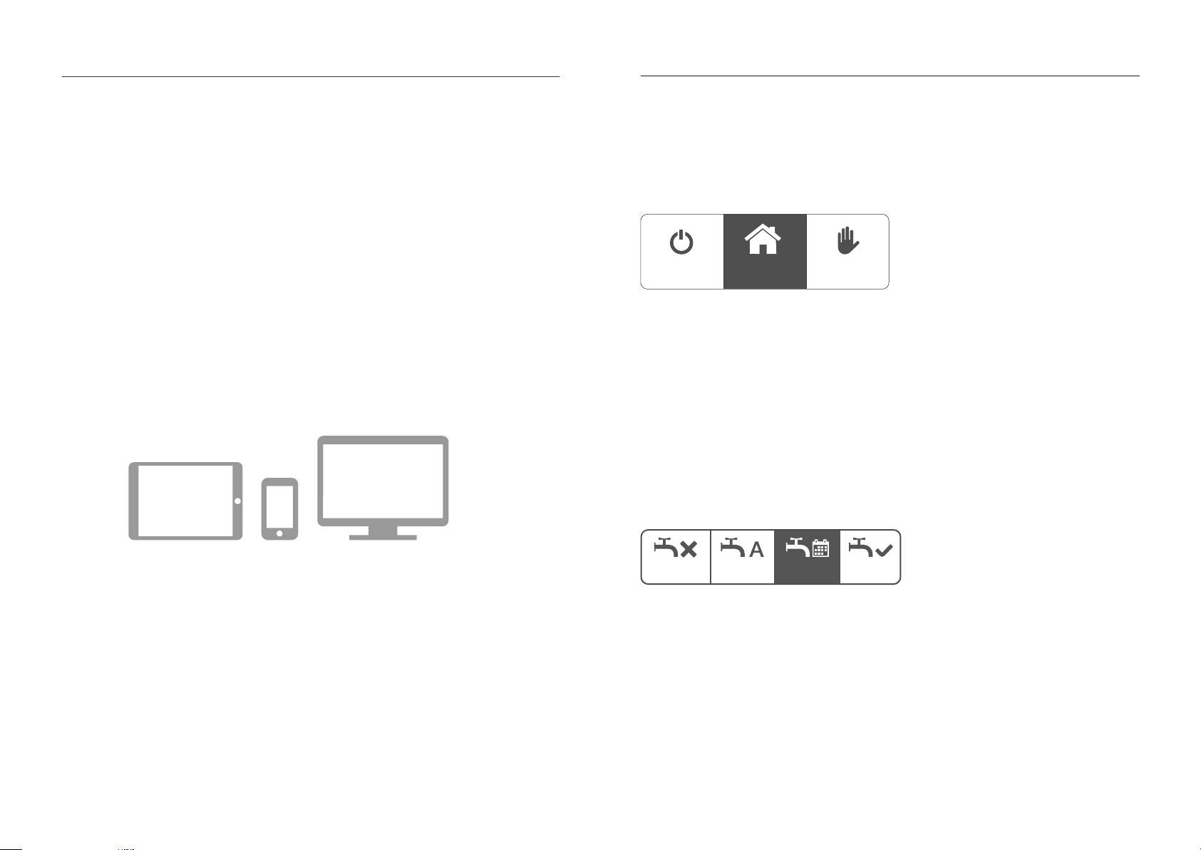
tado° is built for mobile phones and web use. Accordingly, tado° settings are most
comfortably controlled using the tado° mobile app. It is available for iOS (> Version
7.1), Android (> Version 2.3) and Window Phone (> Version 8.1). The download is free.
Besides control of settings and management of data, the tado° app also provides a
detailed report of the heating history and a feature to compute a savings estimate.
The tado° Web App is accessible on computers and tablets and contains the same
features as the mobile app.
Heating Operations
There are three different heating operations.
AutoOff
Off: When set to Off, tado° only heats when the room temperature drops below 5°C to
advoid frost damage.
Auto: When set to Auto, tado° controls your heating based on your location and schedule. You can adjust your prefered home and sleep temperatures. The optimal away
temperature is set by tado° automatically.
Manual: When set to Manual, tado° keeps the room temperature at the selected set
point.
Hot Water
For hot water there are four operations.
Off Auto ManualSchedule
Manual
Off: When set to Off, no hot water is prepared.
Auto: When set to Auto, tado° prepares hot water when you are at home.
Schedule: When set to Schedule, tado° prepares hot water according to the settings
in the dedicated hot water schedule. It can be set in the web application.
Manual: When set to manual, tado° prepares hot water constantly.
tado° – Technical Documentation V1.0
4
Page 7
Smart Thermostat UI
Smart Thermostat UI
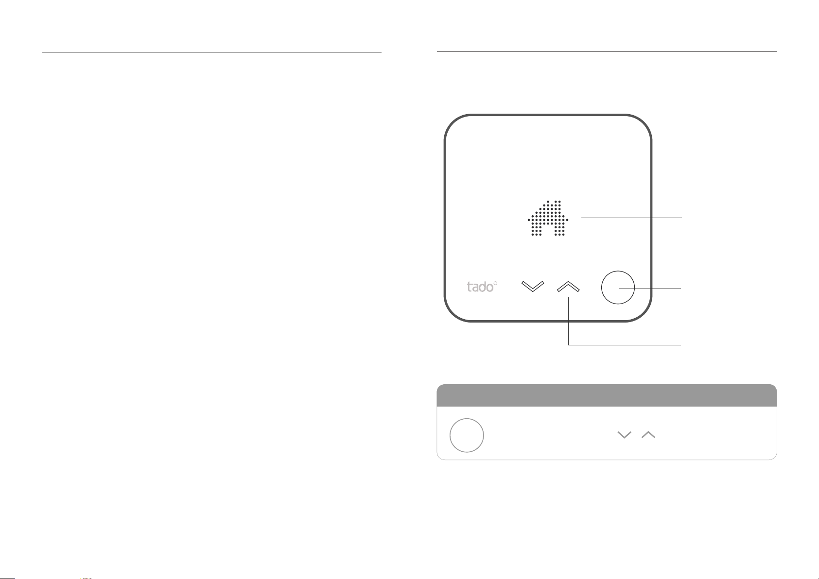
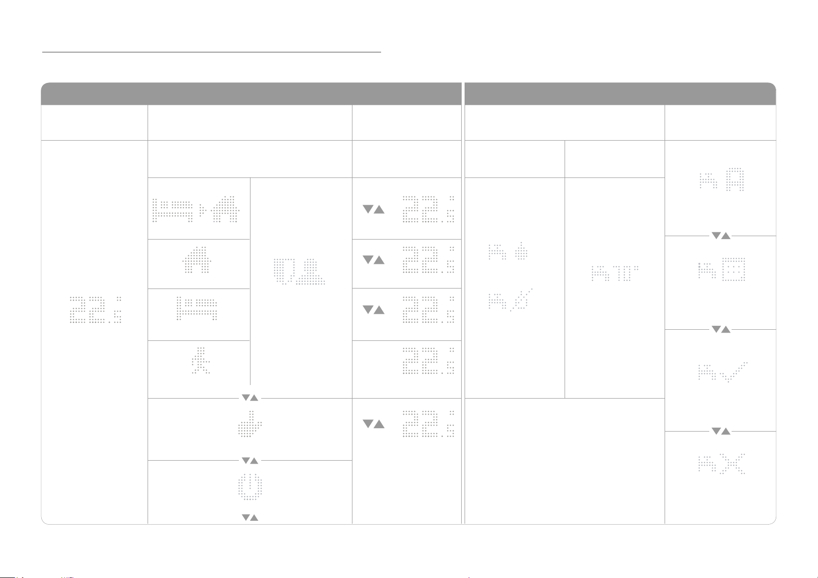
tado°s Smart Thermostat has a user interface which is activated by pressing the button
on the bottom right. First the current temperature is displayed. The mechanical button
on the bottom right can be used to ip through the menu. The next press switches
to the Operation / Mode screen. After pressing the button once more, the setpoint
temperature is displayed and can be adjusted using the cap-touch buttons, which light
up when settings can be changed. On heating systems that support hot water prepe-
ration, the current hot water state (on/off or temperature on specic systems) and hot
water operation are accessible by pressing the mechanical button again.
LED matrix display
Mechanical push button
Control elements
the mechanical button
activates and traverses
through the menu
Touch arrows
switch operation and adjust setpoint temperature
tado° – Technical Documentation V1.0
5
Page 8
Smart Thermostat UI
State
(press once)
Current Temp.
Operation / Mode
(press twice)
Auto Operation Shown for digital bus
Preheat (Animation)
Home
Sleep
Away
HEATING HOT WATER (not supported by all heating systems)
Change Settings
(press three times)
Shown for relay hot
Home Temp.
Home Temp.
Privacy Mode
Sleep Temp.
Not
setable
Away Temp.
Hot Water (not supported by all heating systems)
State
(press four times)
water systems
Hot Water On
Hot Water Off
hot water systems
Hot Water
Current Temperature
Hot Water Operation
(press ve times)
Hot Water
Auto Operation
Hot Water
Schedule Operation
Hot Water
Manual Operation (ON)
Manual Operation
Off
Man Temp.
Hot water
Off
tado° – Technical Documentation V1.0
6
Page 9
System Components – tado° Bridge
link
router
internet
tado° Bridge
internet
link
router
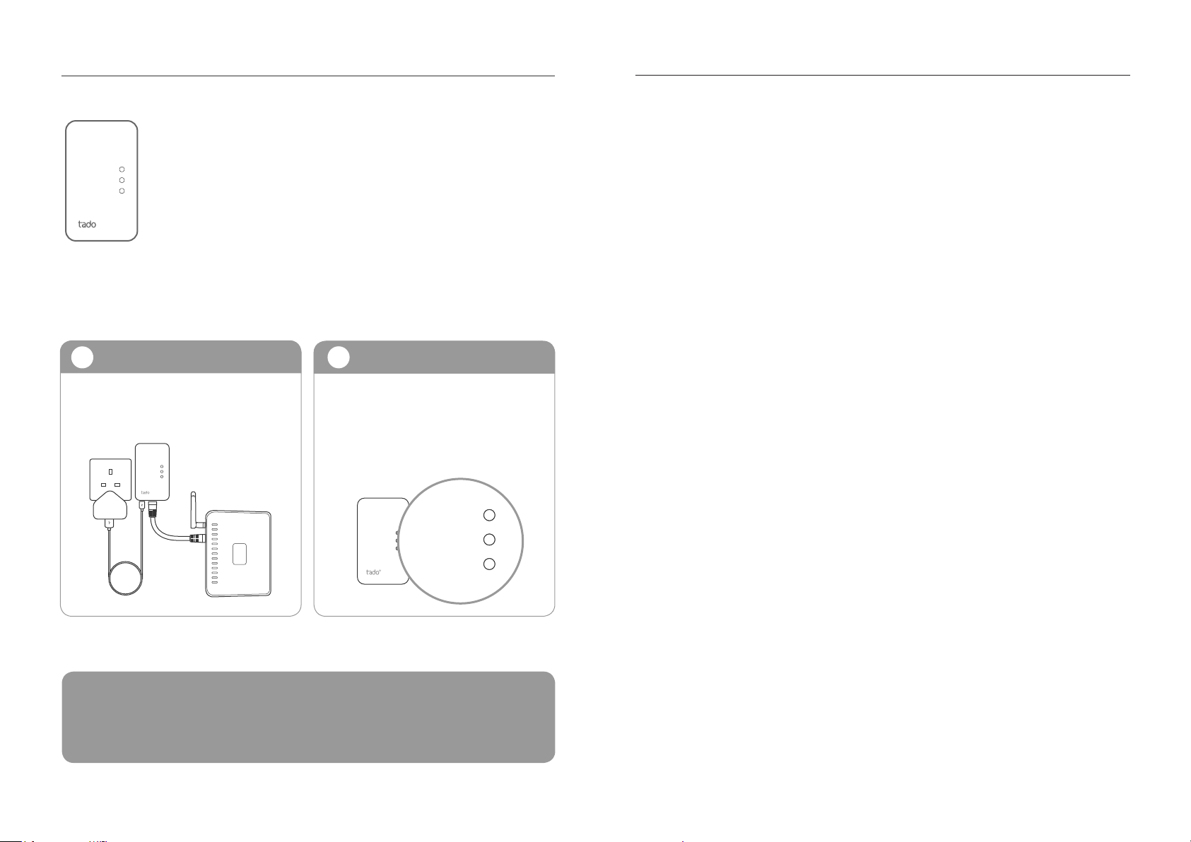
The tado° Bridge is the intermediary device between a tado°
Smart Thermostat and the tado° Servers. It is connected to a
router via an ethernet cable and communicates wirelessly with the
Smart Thermostat.
Connecting the Bridge
Connecting Checking
1
Connect the ethernet port to the router
and the USB port to power via the power
adapter.
link
router
internet
2
The Bridge should be connected and
checked before proceeding with the
installation of the tado° Smart Thermostat
and/or the Extension Box. The “router” and
“internet” lights must be solid.
link
router
internet
TROUBLESHOOTING: If the Bridge is unable to connect to the router (“router” light
continues to ash) or to tado° servers (“internet” light continues to ash) check the ethernet cable and/or reset the device by unplugging and plugging the power cable back in. If
the Bridge is still unable to connect, there may be an issue with the conguration of the
router. More information is available at tado.com/support.
tado° – Technical Documentation V1.0
7
Page 10
System Components – tado° Smart Thermostat
tado° Smart Thermostat
The tado° Smart Thermostat replaces existing thermostats
or acts as a wireless thermostat together with the tado°
Extension Box for heating systems that do not yet have a
thermostat. It measures room temperature and allows to
modify operation and set point temperature. If it is wired to
the boiler it directly controls the heating. If is is not wired, it
communicates to the boiler via the tado° Extension Box.
The tado° Smart Thermostat is powered by three AAA batteries which are included in the package. The paper strip must
be removed from the thermostat to activate the power supply. Batteries typically last for two years. tado° will inform you
via email and/or push notication when it is time to replace
the batteries.
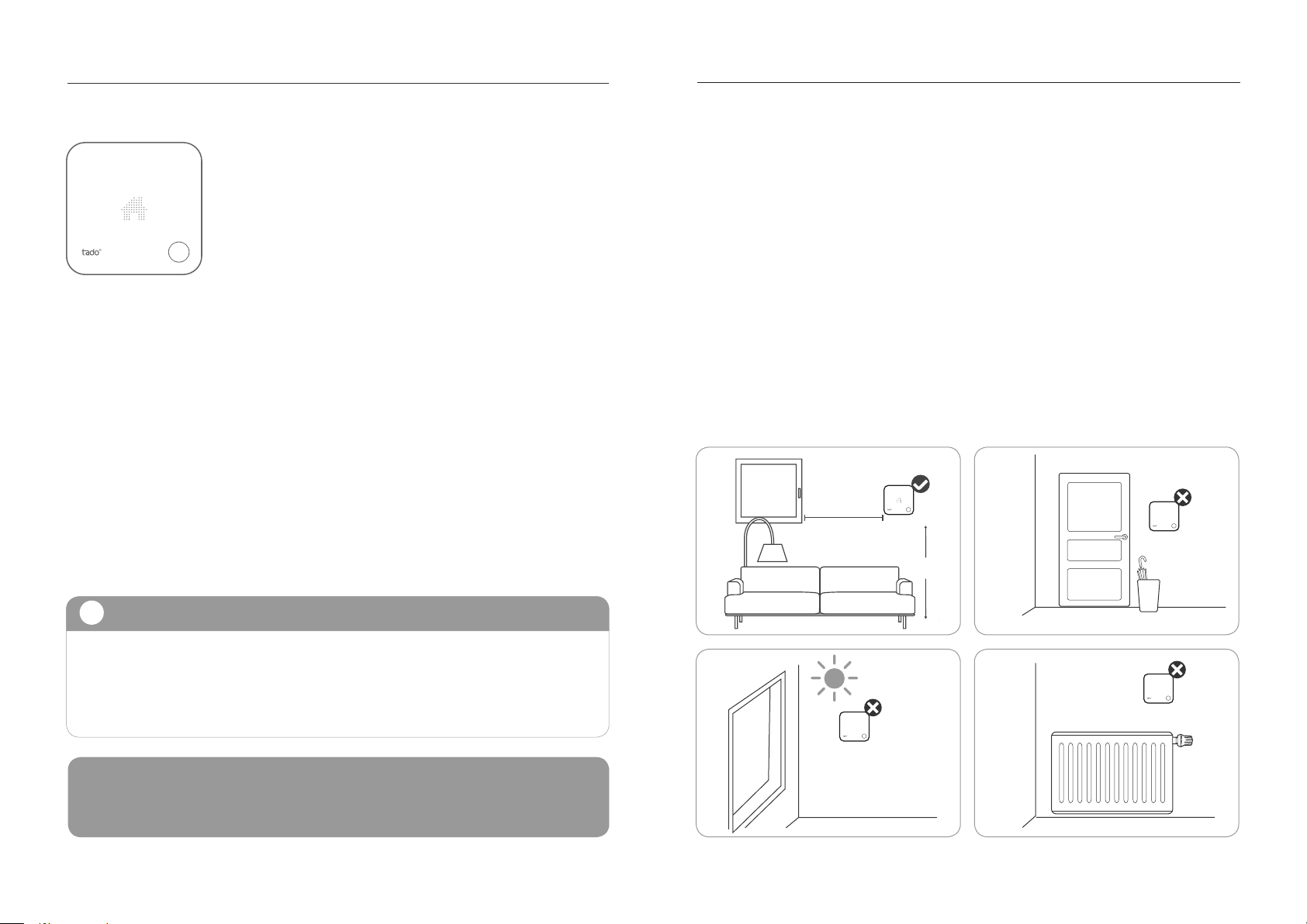
Correct Placement of the Smart Thermostat
In those cases where tado° Smart Thermostat does not replace an existing wired
thermostat, it can be placed in any appropriate location. When installing the Smart
Thermostat please observe the following points:
• place the Smart Thermostat in a location which is representative for the temperature which should be set. This is usually the living room
• place the Smart Thermostat on an inside wall at approx 1.5 m from the ground
• do not place the Smart Thermostat in a place where it is exposed to direct sunlight
at any time of the day
• place the Smart Thermostat away from any draft (near a door or window) or heating sources such as radiators or electric devices
1,50m
tado° Installation
i
tado° provides installation instructions specic to every heating setup. Those
instructions are provided as online webow. This documentation at hand is no
replacement of these instructions and is a documentation of tado° devices and
features, not of the installation process itself.
WARNING: While the self installation of the tado° system is possible, tado° strongly
recommends booking of a professional installation by one of our tado° installation professionals.
tado° – Technical Documentation V1.0
8
Page 11
System Components – tado° Smart Thermostat
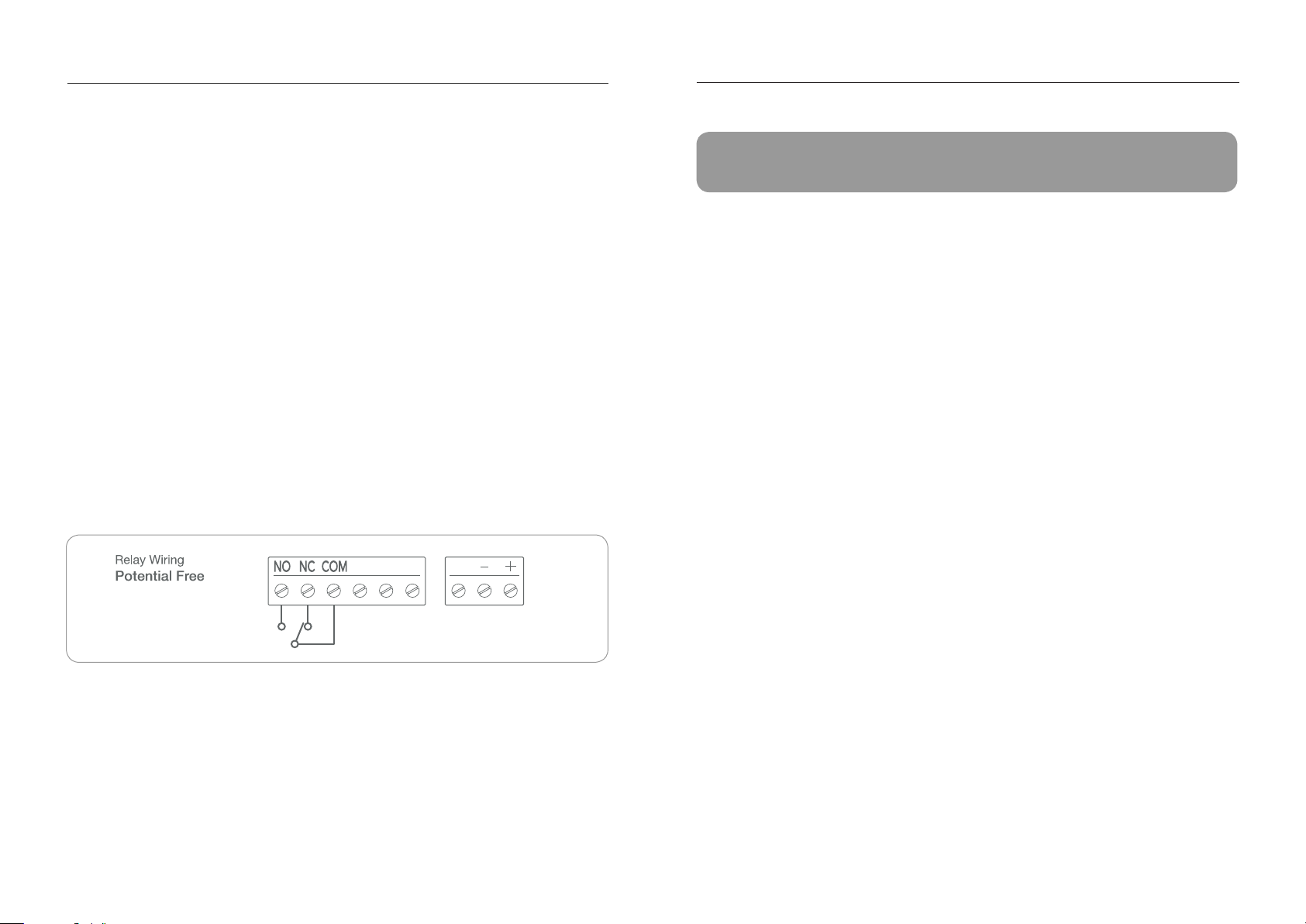
Wiring
tado°s Smart Thermostat supports both 230V and low voltage interfaces. The wiring
diagram on the back of the device shows the wiring for the relay operation, three isolated parking slots for excess wiring (from the thermostat which is to be replaced) and
three low voltage terminals for analog and bus connection.
When replacing a relay thermostat, connect COM and NO and optionally NC (if
present in the current thermostat). Place any additional wires, such as a neutral wire
into the parking slots without labeling next to the relay terminals. They do not have any
function other than safely parking excess wires.
To replace an analog thermostat, use the three low voltage terminals on the right hand
side. The analog output is connected to “A”, ground (GND) to “-” and the positive input
(Vcc) to “+”.
When replacing a two-wired digital thermostat, the two low voltage terminals labeled
with “-” and “+” are used. Typically digital bus interfaces are protected against polarity
reversal, thus the order of connection does not matter.
A
TROUBLESHOOTING: The tado° Smart Thermostat can be reset by pressing the but-
ton on the front for more than 8s.
When replacing wireless thermostats, the additional purchase of the tado° extension kit
is recommended. tado°s Extension Box replaces an existing external reciever, extenal
controller or is connected directly to the boiler. The tado° Smart Thermostat can then
be placed in any suitable location without any wired connection being required.
tado° – Technical Documentation V1.0
9
Page 12
System Components – tado° Extension Box
tado° Extension Box
The tado° Extension Box acts as a communication link
between the tado° Smart Thermostat and the boiler. It
replaces extenal controllers, external receivers or is directly connected to the boiler.
The Extension Box is powered by 230V mains connection
for relays and by low voltage power supply when connected
to analog or digital interfaces. For potential free relay wiring,
an additional two wire power supply cable maybe required
which is provided by tado° upon request.
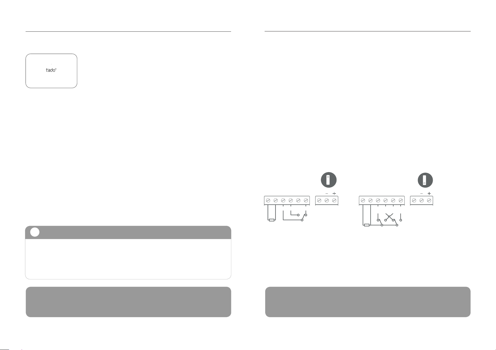
Wiring
tado°’s Extension Box has both 230V and a low voltage interfaces. Two relay wiring
congurations are possible and are distinguished by two different jumper positions.
The rst wiring option is a potential free wiring connection, where the power supply is
separated from the relays. This wiring option is to connect low voltage single relays.
In case a UK standard backplate is present and wired as a 230V dual relay (central
heating and hot water) the tado° Extension Box can simply be mounted on the existing
backplate and does not require any rewiring.
For UK standard backplate where only one relay is wired, some rewiring might be
required such that the wires correspond to tado°s “Relay Wiring 1” as indicated at the
back of the Extension Box.
Relay Wiring 1
Potential Free
NL 12 34
COM NC NO
1
A
Relay Wiring 2
Switched Live
NL 12 34
HW
OFFCHOFFHWONCHON
2
A
tado° Installation
i
tado° provides installation instructions specic to every heating setup. Those
instructions are provided as online webow. This documentation at hand is no
replacement of these instructions and is a documentation of tado° devices and
features, not of the installation process itself.
WARNING: While the self installation of the tado° system is possible, tado° strongly
recommends booking of a professional installation by one of our tado° installation professionals.
TROUBLESHOOTING: The tado° Extension Box can be reset by pressing the button on
top for more than 8 seconds. After a reset, the box will start to look for a connection to the
tado° bridge and the LED will blink during that process.
tado° – Technical Documentation V1.0
10
Page 13
Support Technical Specications
For online support, please visit:
tado.com/support
For phone support, please call:
UK: +44 (0)20 35144881
DE: +49 (0)89 416156640
tado° Smart Thermostat (Model RU01)
Dimensions: circa 104 x 104 x 19 mm (L x B x H) / circa 132 g
Operating voltage: 5-36V DC 0.2A / 4.5V DC (3xAAA batteries, 1,200 mA/h)
Relay: max. 240V AC 6(4)A / max. 30V DC 6(4)A
Radio: 868 MHz, Mesh (6LoWPAN)
Display: 10 x 19 LEDs, 32 x 20 mm
Material: PC+ABS
Button: 1x Mechanical; 2x Capacitive Touch
Colour: white, at
CE, RoHS
tado° Extension Box (Model BU01)
Dimensions: circa 150 x 102 x 28 mm (L x B x H) / circa 210 g
Operating Voltage: 5-36V DC 0.2A / 100-240V AC 0.2A
Relay: max. 240V AC 6(4)A / max. 30V DC 6(4)A
Radio: 868 MHz, Mesh (6LoWPAN)
Material: PC+ABS
Colour: white, at
CE, RoHS
tado° Bridge (Model GW02)
Dimensions: circa 89 x 52.5 x 25.5 mm (L x B x H) / circa 61 g
Operating voltage: 5 V
Radio: 868 MHz, Mesh (6LoWPAN)
Material: PC+ABS
Colour: white, at
CE, RoHS
tado° – Technical Documentation V1.0
11
 Loading...