


© Tactical Technologies Inc
The JOEY
TRANSCORDER
Synthesized Voice Transmitter
PLUS
Solid State Recorder
All-in-one Package
CTR-751/V
OPERATING
INSTRUCTIONS
Rev 1c

DESCRIPTION
The Tactical Technologies Inc. Model CTR-751/V series ("Joey") is a 1 channel 1/2 Watt VHF-FM synthesized voice
transmitter, combined with a solid state recorder.
The transmitter and recorder combination ("Transcorder") requires 9 volts DC for its power supply, utilizes an external
antenna for the transmitter, and a single microphone for both the transmitter and recorder operations. It can be optionally
equipped with a scramble for added security.
The CTR-751 series transmitter operating frequencies are programmed via an open serial port on an IBM compatible PC.
The transmitter's firmware is compatible with ANY vintage IBM compatible PC's communications program - such as
Microsoft's Hyperterminal. The recorder can use the same PC serial port. Proprietary software for recorder operations is
included. You can also program the transmitter in the CST-751/V direct from the panel of a Citation 20 Synthesized
Intelligence Receiver Recorder Kit!
Features of the Joey Solid State Recorder include: Easily concealable, Multiple MONO recordings, Very low power consumption, 2 Selectable sampling rates of 8 or 11 kHz, ability to download individual recordings, RS232 interface to standard PC
serial port, raw data download with audit trail identifiers and checksum information. The Joey recorder is also available with
either a 64Mbyte or 128Mbyte memory chip which respectively yields record times from 100 minutes to 440 minutes.
The supplied instructions are for the Window 95, 98, or XP operating systems.
The Joey
TM
Transcorder
TM
Voice Transmitter and Solid State Recorder
All-In-One Unit

TRANSCORDER OPERATION SETUP
1.) Connect the external antenna to the CTR-751 by inserting the
male end of the SMC type antenna connector on the transmitter to
the female connector end on the wire antenna. Twist the connector
clockwise to tighten (HAND TIGHT ONLY!).
2.) Connect the Microphone. Determine which of the two supplied
microphone configurations are best for your application: the long
leadwire microphone or the short/stubby microphone. Connect the
microphone by inserting the female end of the friction-locking 2 pin
connector on the microphone cable into the male connector found on
the CTR-751. This connector is keyed for proper installation. Push
the connectors firmly together.
3.) Connect the power lead to the transmitter. Connect the 9 VDC
battery lead by inserting the female end of the friction-locking 6 pin
connector on the power cable into the male connector found on the
CTR-751. This connector is keyed for proper installation. Push the
connectors firmly together.
4.) Any 9 VDC power supply (batteries, regulated supply, etc.) can be
applied to the CTR-751. When using disposable batteries, always use
either Alkaline or Lithium cells. Lithium cells are recommended for
longer operating life.
NOTE: DO NOT APPLY 12 VDC DIRECTLY TO THIS UNIT.
NOTE: THE CST-751 IS REVERSE POLARITY PROTECTED,
HOWEVER PLEASE BY SURE TO CONNECT THE + AND LEADS TO YOUR POWER SUPPLY CORRECTLY FOR PROPER
OPERATION OF THE TRANSMITTER. PAY PARTICULAR
ATTENTION TO THE MARKINGS ON SMALL BATTERIES.
WHEN USING THE FLYING LEAD CONNECTORS, THE
BLACK LEAD IS NEGATIVE AND THE RED OR WHITE
LEAD IS THE POSITIVE.
5.) Once power is applied to the CTR-751, the internal solid
state recording unit is ON and RECORDING. To turn the
recorder OFF, simply disconnect the power. Each time power is
applied to the unit, a new recording session begins.
6.) Turn ON the VHF transmitter. Locate the ON/OFF slide
switch. It is found between the antenna connector and the
microphone/power connectors on the top of the CTR-751. Turn
the transmitter ON by sliding this switch AWAY from the RED
DOT. The transmitter can be turned OFF by sliding the switch
TOWARDS the RED DOT.
NOTE: Once power is applied to the CTR-751, only the
transmitter can be turned ON or OFF. The recorder is always
ON.
7.) To turn the unit completely OFF, remove the power supply.

INSTALLING YOUR TRANSMITTER SOFTWARE
1.) The computer program supplied to install the frequencies into
your CTR-751 transmitter is a module written for Microsoft's
Hyper-Terminal. HyperTerminal is supplied with Windows 95 and
98 and XP. If HyperTerminal is installed, you can proceed. If you
have not installed this program onto your computer, please do so
at this time.
Installing HyperTerminal in Windows:
a.) Select "START" from the Windows Task Bar
b.) Select "Settings" - "Control Panel" from the Start Menu
c.) Select "Add/Remove Programs" from the Control Panel
d.) Select the "Windows Setup" tab at the top of the window
e.) Double-click on "Communications" in the 'components'
window.
f.) Click the box next to "HyperTerminal". This puts an X in the
box.
g.) Click "OK" at the bottom of the window.
h.) Click "OK" at the bottom of the new window.
i.) Follow the on - screen instructions about inserting your
Windows Installation CD.
2.) Install the HyperTerminal TTI Transmitter Programming
Module:
a.) Insert the supplied 3 1/2 inch floppy disk into you computer's
disk drive.
b.) Select "START" from the Windows Task Bar.
PROGRAMMING YOUR TRANSMITTER OPERATING
FREQUENCY
FROM AN
IBM COMPATIBLE PC
SERIAL PORT
1.) Connect the CTR-751 TX programming cable to the top of
the transmitter via the 6 pin connector. This connector is keyed
for proper installation. The cable will be marked with a "TX" indicating it is the cable for transmitter programming.
2.) Connect the D style 9 pin female connector to an open serial
port on your IBM compatible computer. If your computer's serial
port is a 25 pin connector, you will need to use a DB25 to DB9
serial adaptor (not included).
3.) Start the "TTI Transmitter Programming" software by
clicking it's icon located on the Windows Desktop.
4.) You must know the number of the Serial (Com) Port you
have attached the transmitter to. The software comes ready to
work with Com 1. If you are using Com 2, 3, or 4, you must
perform the following:
a.) Select "File" - "Properties" from the HyperTeminal Task
c.) Select "RUN" from the Start Menu
d.) Type "a:\setup" in the white bar
e.) Select "OK"
f.) Follow the on screen instructions.
g.) Remove disk when finished.
JOEY'S VHF VOICE TRANSMITTER
Bar.
b.) From the "Phone Number" tab, select your Com Port in the
"Connect Using" pull down menu. Select the "Direct to Com
___" line that correlates to your Com Port.
c.) Select "OK" from the bottom of the window
d.) Your Com Port selection is automatically saved.
5.) Connect a 9 VDC battery to the battery terminal leads found
on the programming cable, and turn ON your Transmitter.
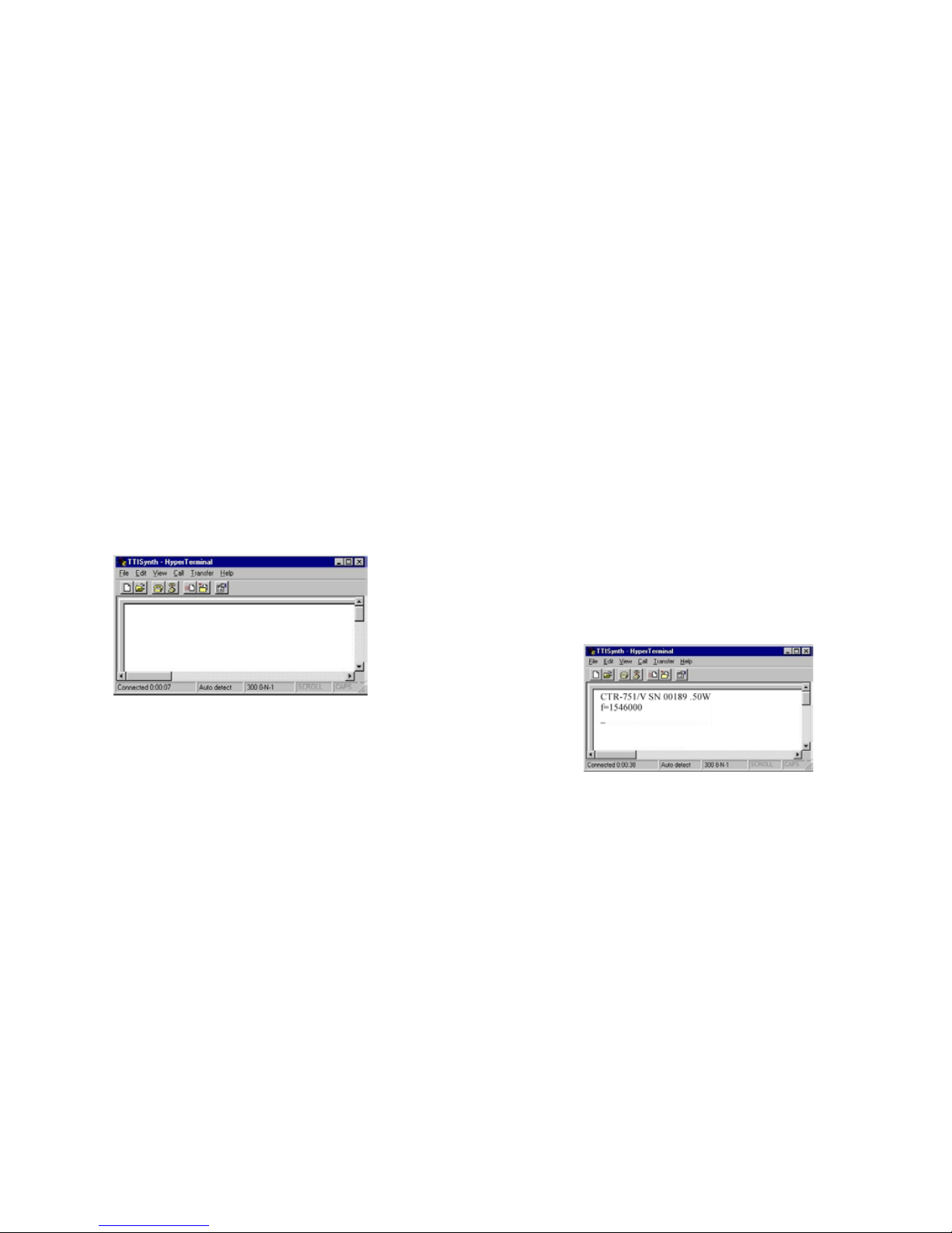
At this time, your computer screen should look similar to the
following screen shot:
Here are some commands to become familiar with:
f..........Begins the New Frequency programming
sequence.
v..........Verifies the frequency that is currently
programmed in the transmitter.
c.........Selects CLEAR transmission mode (for
units equipped with scrambling).
s..........Selects SCRAMBLE transmission mode (for
units equipped with scrambling).
Remember: All commands are lower case letters.
6.) Begin by VERIFYing the information about your transmitter.
Type a v.
Immediately upon your entering a "v", the program will report the unit's
ID (CTR-751/V) , and the frequency that is programmed into the current
channel. If your transmitter is equipped with scrambling capabilities, this
will be noted with an "S" after the model number (CTR-751/VS), and
whether the unit is in scrambled mode or clear mode (noted with a "c"
or an "s" before the frequency notation). The screen will look something
like this:
7.) Program your frequency
Type an f.

The computer will respond with "=1", as follows:
8.) The "1" is the 'hundreds" digit in your frequency (ie: 1xx.xxxx
Mhz). Now type the next 5 digits of your frequency.
Here is some information on VALID frequencies:
Your available frequencies are spaced in 12.5 kHz steps, beginning
with 150.0000 Mhz and ending with 174.0000 Mhz.
Simply put, "12.5 kHz steps" means that your frequency must end in
any of the following configurations:
xxx.x000
xxx.x125
xxx.x250
xxx.x375
xxx.x500
xxx.x625
xxx.x750
xxx.x875
xxx.x000
The first available frequency to you is 150.0000 Mhz. The
second is 150.0125 Mhz. The third is 150.0250 Mhz. And so on
through 173.9750, 173.9875, and 174.0000.
Your frequency will always start with a "1" - so that is pre-
programmed for you. And the last digit in your frequency will be
dictated by the second last digit, and the program will select that
last digit for you as well.
So, with a 7 digit frequency (xxx.xxxx Mhz) - and the first and
last numbers programmed for you (Dxx.xxxD Mhz) - you will
only have to enter 5 digits.
The first programmed digit (tens position) must be either a 5, 6,
or 7. The second (ones position) can be any number. The third
(1/10th position) can be any number. The fourth (1/100th
position) can be any number except a 4 or a 9. And the number
you select here will dictate the fifth number you are to program.

Program a 0 or a 5, your next number must be a 0. Program a 1 or
a 6, and your next number must be a 2. Program a 2 or a 7, your
next number must be a 5. Program a 3 or an 8, your next number
must be a 7. The previous list of examples shows this clearly.
And the 'last' digit in the frequency (1/10,000th position) will be
determined by that second last digit. If the second last digit is a 0
or 5, the last digit will be a 0. If the second last digit is a 2 or a 7,
the last digit will be a 5.
After you enter your valid 5 digits, the cursor will move to the
next line, similar to the following screen shot:
At this point, the program is awaiting another instruction from
you; either an f, v, c, or s. (Remember: c or s are only valid
entries on scrambled units.)
FOR SCRAMBLED UNITS:
At any point in the sequence where the program is awaiting an
input instruction, you can set the 'scramble' or 'clear' mode by
typing sv ("s" sets scramble mode, plus the "v" verifies the
programming) or cv ("c" sets to clear mode, plus the "v" verifies
the programming).
9.) After you have finished validating your entries, turn off your
transmitter, disconnect the cables, and close the computer
program.
Here is some information on INVALID frequencies:
If you enter an invalid frequency, the software will respond on
the screen as follows:
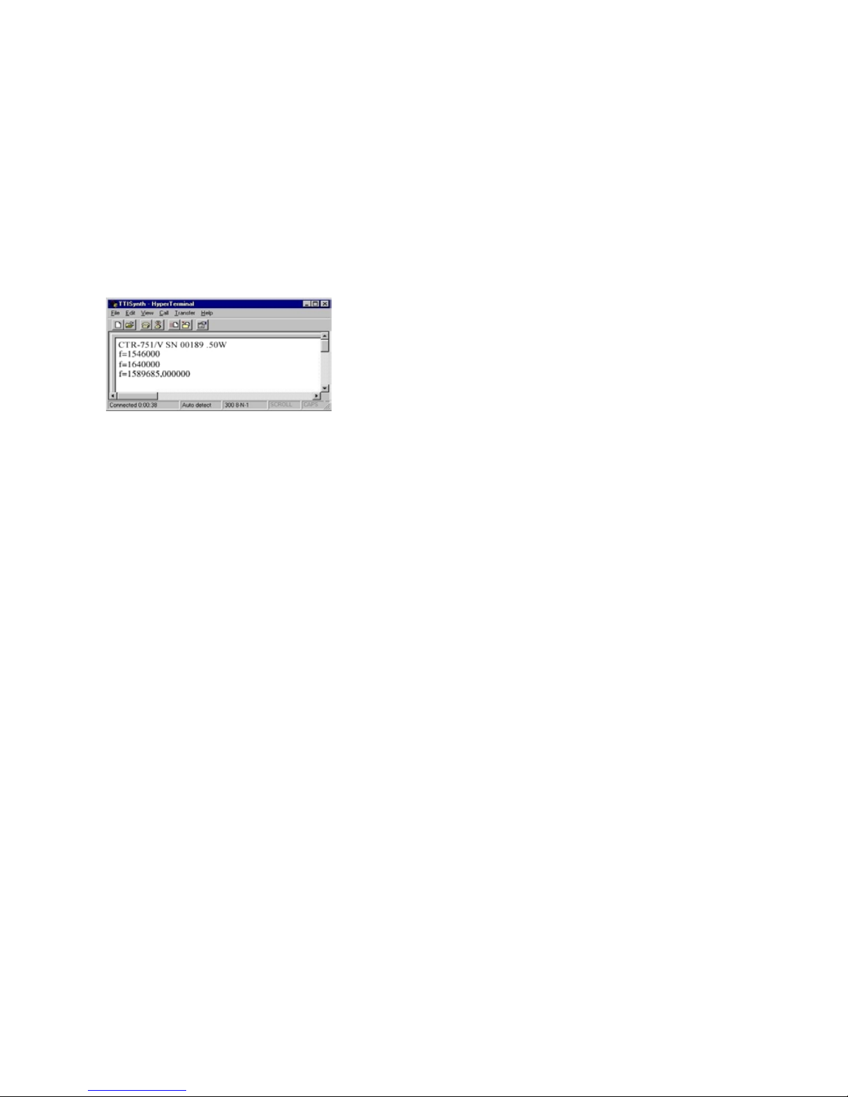
As you can see from the example, the frequency entered was
158.9685 MHz. This is invalid per the rules. The software
responds with a comma, then 6 zeros, and a carriage return. At this
point, the program has not updated your transmitter, and is
awaiting an input instruction (f, v, c, or s) from you. Enter an f
so that you may re-enter a correct, valid frequency.
Programming from a Citation 20 Receiver/Recorder Kit
Please consult your Citation 20 Operations Manual for directions
on programming transmitters directly from the Citation 20,
WITHOUT a separate computer!

The Joey's solid state recorder has been designed by Geonautics
International, an Australian Company, who is widely known in the
electronic surveillance field for their well engineered devices. The
recorder used in the Joey comes from their Whisper line of
equipment, and is a modified version of their A1 Whisper Tag.
The Whisper software package is used to control and download the
Joey Recorder. The program also offers limited playback features
through the standard Windows multimedia player.
INSTALLING YOUR RECORDER SOFTWARE
The computer program supplied to setup, playback, and maintain
the recordings you will make with your CTR-751 transcorder is a
module written by Geonautics for their stand alone Whisper line of
recorders. It is designed to operate under Microsoft's Windows 95
and 98 and XP operating systems. The software is called the
Whisper Player.
Installing the Whisper Player in Windows:
Insert the CD into your computer. If 'autorun' is enabled, the
installation program will automatically start. If it does not:
a. Click the START button.
b. Select RUN, and type
D:\ie\iesetup.exe
(where D is the letter of your CD-ROM drive).
c. Select OK
d. Follow the on-screen instructions
JOEY'S SOLID STATE RECORDER
Running the Whisper Player software:
a. Click the START button.
b. Select PROGRAMS
c. Locate the GEONAUTICS selection and point to it
with your cursor.
d. Left click your mouse on the selection titled
WHISPER.

RECORDING AND PLAYBACK
NOTE: If the REC programming/download cable is connected to the
Joey, recordings can only be initiated via the Whisper Player
software.
Each time power (or a short) is applied a new FILE number and
recording will be created on the device.
Configuring the recorder for operations - programming
1.) Connect the CTR-751 REC programming/download cable to the
top of the Joey via the 6 pin connector. This connector is keyed
for proper installation. The cable will be marked with a "REC" indicating it is the cable for transmitter programming.
2.) Connect the D style 9 pin female connector to an open serial
port on your IBM compatible computer. If your computer's serial
port is a 25 pin connector, you will need to use a DB25 to DB9
serial adaptor (not included).
3.) Start the "Whisper Player" software.
4.) You must know the number of the Serial (Com) Port you have
attached the Joey to. The software comes ready to work with Com
1. If you are using Com 2, 3, or 4, you must select that port via the
"Serial Port" area of the software. Your serial port should be
configured for a data transfer rate of 115k baud.
5.) Apply power to the Joey by attaching a 9 VDC battery to the
battery connector found on the REC programming/download cable.
Once power is applied, the Joey and the software will 'handshake'.
After about 10 seconds, the software will report that the Joey is
ONLINE via the following response: $WSP, ONLINE. You will
see this in the Whisper Player Communications Window found in
the lower left corner of the software screen.
NOTE: You must wait for the Joey to report that it is ONLINE
before you can continue. If the unit does not report, disconnect
the 9 VDC battery, wait 5 seconds, then reapply the power to the
unit.
6.) Press the "LIST" button to see if the recorder has files
previously recorded on it. If the Joey has files on it, your
computer screen will look something like this:

Listing progress is reported in the Communications Window.
7.) If there are files on the device and they have not been
downloaded, and you want to save these files, see the section on
DOWNLOADING
8.) Select the "Sample Rate" and 'Quantisation" settings. These
commands change the "free" recording time available.
A "Sample Rate" of 8kHz captures 4kHz voice which is roughly
equivalent to telephone quality. Alternatively the full voice range
of 5.5kHz can be reproduced using the 11kHz setting.
"Uniform" quantisation provides the best quality as it stores each
voice sample independently. The "Non Uniform " setting uses a
logarithmic scale to store delta differences between successive
samples which increases the record time with only a minimal
quality decrease.
How to make a recording from within the Whisper Player Software
To make a test recording, ensure the microphone is attached to the
Joey, and select "Record". De-select "Record" to finish the
recording. The listing is refreshed automatically at the end of the
recording. Use the "List" command to refresh the list of recordings
manually.
NOTE: Recordings with a duration of less than approximately 10
seconds will not be shown in the directory listing.
The lines of information on the recorder file listing gives the
following information about each recording:
a.) Sequential Number - each file on the recorder is given a
number in sequence which serves two purposes. First, the unique
number gives individuality and identity to the file. Second, the
number tells you how many individual files have recorded with
that device. Your brand new Joey will not start with file number
1, because files are created during the manufacturing and QC
stages of production.
b.) Time - duration of the recording, listed in real time.
c.) Quantisation setting for that recording
d.) Sample Rate for that recording
e.) File size for that recording in kBytes.
Once the files from the Joey are "LISTED", then you can
download and save them, and you can clear the recorder for
future use.
How to Download and Save files
1.) Set up your Download Path. The Download Path tells the
Whisper Player Software the location it will place the file after
the download.
a. On the Command Line at the top of the software
window, left-click on PATH
b. Select DOWNLOAD DIRECTORY, and choose
where you would like your files downloaded to.
c. Your Path will be displayed on the bottom of the
software window. This Path will be maintained by the Whisper
Player until you change it.
NOTE: It is recommended that downloads are burnt directly to
CD using suitable software such as Roxio's Direct-CD package

available from www.roxio.com. (In Windows XP, you can simply
select your CD-R drive for downloading).
2.) Select the recording to be downloaded by left-clicking on the
file identifier in the List Box. "Ctrl and Shift" keys may be used to
make multiple selections for downloading.
3.) Once the files are highlighted, press the DOWNLOAD button
to begin the download. You will see the software report it's
progress to you in the Communications Window. The file(s) will be
downloaded and immediately saved to your PATH.
Single files can be downloaded by double clicking on the recording in
the list window. Double-clicking starts the download automatically.
Information on SAVED FILES
The Joey's Saved File Naming Convention utilizes three variables
that make up the automatically assigned file name:
1.) The "Prefix" - assigned by you the user, and is used to identify
the recording. The Prefix can be any combination of letters and
numbers, and is commonly your Casefile name. You assign the
prefix PRIOR to download via the box near the top middle of the
Whisper Player Software. Type in the name of the prefix you
want the saved filename to have, THEN download the file. If you
leave the prefix window blank, the filenames will NOT have a
prefix.
In our screen example, all the saved files would have a Prefix of
TEST
2.) The Joey's ID number - this number is unique to your Joey and
cannot be changed by you. This is NOT the Joey Transcorder
Production Serial Number, but is a special number assigned to the
recorder only.
3.) File Number - this is the same sequential number as you saw
noted in the LIST command.
Three separate and distinct files are created for each download:
File 1: prefix.joey_id.file_number.img
This is an image of the memory stored in the Joey recorder.
File 2: prefix.joey_id.file_number.txt
This is a text report detailing the authenticity of the download.
File 3: prefix.joey_id.file_number.wav
This is the Windows(TM) WAV file - this is the audio playback
file. The downloaded WAV file can be played via the CD-like
multimedia controls found in the Whisper Player Software, or by
any WAV file player, such as the Windows Media Player supplied
by Microsoft.
Playing back your downloaded files
The Whisper Player Software has it's own 'player' built right into
the software.
1.) Press the BROWSE button. It will open the file directory
specified by your PATH setting. From here, you can open

downloaded and saved recordings, or explore your computer to find
other WAV files for playing.
2.) Double-click on the WAV file you wish to playback. The name
of the file will appear in the box to the left of the BROWSE
button.
3.) There are three controls on the Player:
> - select for PLAY, de-select for STOP
|| - select for PAUSE, de-select for CONTINUE
|<< - select for REWIND TO BEGINNING
NOTE: A single downloaded file, or the last downloaded file in a
list, is automatically selected for playback.
Clearing the memory of the Joey
Once all required files have been downloaded, use the "Format"
button to clear the entire recorder.
NOTE: Individual recordings cannot be erased.
WARNING: BE SURE YOU HAVE DOWNLOADED ALL
IMPORTANT FILES BEFORE USING THE FORMAT COMMAND. THIS COMMAND IS NOT REVERSIBLE.
Closing the Whisper Player Software
Press the DONE button to close the software.
File Integrity
To ensure validity of the recorded data sets and to safeguard
continuity of evidence, the Joey Recorder implements a number
of integrity checks.
1) Each Joey Recorder is given a unique UNIT ID at the time of
manufacture. The UNIT ID cannot be changed by the user.
2) Every recording made by the Joey is given a unique FILE
NUMBER. The FILE NUMBER is generated by the Joey and
cannot be nominated by the user.
3) Recordings are made from blocks of data. Blocks are totally
self-contained and represent between 0.05 and 0.1 seconds of
speech, depending on "Sample Rate" and "Format" settings.
Consisting of 528 bytes, the block contains a 512 byte "data
packet" and a 16 byte "header packet". Each block is given a
count or SEQUENCE NUMBER, starting at 1 for the first block
of each recording, and contains a CHECKSUM for the "data
packet" and a checksum of the individual packet CHECKSUMS.
Each and every "header packet" also contains the UNIT ID and
FILE NUMBER.
Thus each 0.05 to 0.1 seconds of recorded sound packets can be
shown to have a valid checksum, belong to a unique recording on
a unique device and be in sequence with its neighbours. The
second CHECKSUM of the packet CHECKSUMS further
validates the integrity of the data. If a corruption occurs or
integrity fails the exact time and span of the dubious data can be

IMPORTANT:
1.) If computer interface is not COM 1, you must select the
correct Com port as described in the instruction.
2.) The transmitter must be ON and powered in order to program
it.
3.) Turn OFF the transmitter when finished programming.
OPERATING NOTES:
1.) Antenna should always be kept vertical for best operation of
the transmitter.
2.) PLEASE always use fresh batteries at the beginning of each
operation.
3.) Check operation of transmitter portion of Joey with a
receiver prior to any field ops.
4.) Practice with this piece of equipment prior to use.
readily identified.
All this information is stored as part of the Geonautics' Audio
Image (*.img) file and can be easily reconverted to a WAV file for
listening. At the time of conversion a text file containing an
integrity analysis of the download is created as a (*.txt) file.
Verifying the IMG File
To verify a previously downloaded IMG file press the "Browse"
button and set the file type to "Raw Image". Select the file to be
reprocessed. A new WAV and TXT report file will be created. The
TXT file contains the summary of possible data discrepancies.
Whisper Player Command Summary
Help - Whisper Help Display this help file
Help - Version Joey hardware version information
Help - About Whisper software version / copyright
information
Path - Download Directory Set the current directory where files will be
stored
Path-Reset Directory Files are stored in the current directory
Download Download any selected recordings
Browse Load a WAV file for playback or an IMG file
for reprocessing
Record Start/Stop a new recording
Format Erase the complete flash memory inside Joey
List List the Joey's current recordings
Sample Rate Set / display current sample rate
Quantisation Set / display current quantisation format
Serial Port Set / display the computers serial port
Done Exits the program

Tactical Technologies Inc
1701 Second Ave
PO Box 91
Folsom, Pennsylvania 19033
USA
TEL: 610-522-0106
FAX: 610-522-9430
 Loading...