

Page 1
UDC 360
UNDER DOOR 4-CAMERA SYSTEM
TACTICAL ELECTRONICS
Products
OPERATION AND
SUPPORT PUBLICATION
PROPRIETARY
TACTICALELECTRONICS.COM
PRODUCTS / EOD T RAINING / R & D / AVIAT ION
DESIGN / ENGINEERING / MANUFACTURING
HEMLOCK FACILITY
2200 NORTH HEMLOCK AVE / BROKEN ARROW, OK / 74012
V: 866.541.7996 / V: 918.249.8326 / F: 918.249.8328
CRUSADER FACILITY
2844 CRUSADER CIRCLE / #100 / VIRGINIA BEACH, VA / 23453
V: 757.689.0476 / F: 757.689.3769
Page 2

PROPRIETARY
2
Page 3
UDC 360
UNDER DOOR 4-CAMERA SYSTEM
3
Manual Contents
Kit Identification
Power-up
Operation
Monitoring Options
Specifications
3
4
5
6-9
10-15
16
Page 4

UDC 360 KIT IDENTIFICATION
OPERATION AND SUPPORT PUBLICATION
One) Under Door Camera 360 (4-camera system)
» Four cameras: forward, upward, left, and right facing cameras
» Internal mini DVR with SD card recording capabilities
» 16GB SD card
» Four 0.005 lux black & white CCD chip at the distal end of insertion panel
» Insertion Panel only 0.262” thick
» IR LED illuminator (1) for flood illumination
» >100mW @ 2400 mHz transmitter onboard
One) Telescoping deployment pole
One) Hard-wire cable (with inclusion of Handheld Monitor Pro)
» Used for hard-wire operation with Handheld Monitor Pro
One) Monitoring option of your choice (Wrist Monitor Pro or Handheld Monitor Pro)
» Handheld Monitor Pro has a 5.0” screen
» Wrist Mounted Monitor Pro gives the operator a 3.5” screen on the arm
One) Storm Case® w/ precision cut foam for stable storage environment
» Unbreakable
» Watertight
» Airtight
» Corrosion Proof
4
Tactical Electronics & Military Supply
Page 5
UDC 360 POWER UP
OPERATION AND SUPPORT PUBLICATION
• The UDC 360 Under Door Camera is powered by four 3Volt Photo Lithium batteries. Most manufacturers of these
cells designate them as size 123 or CR123A. Tactical Electronics systems draw high current; use only GE SANYO,
ENERGIZER, or DURACELL batteries. Testing has proven those batteries to provide the longest run time in our
products.
• Run times will vary, components in this system are designed to optimize power management and power sharing
when hard-wired together. Usage of IR LEDs will also contribute to varied run times.
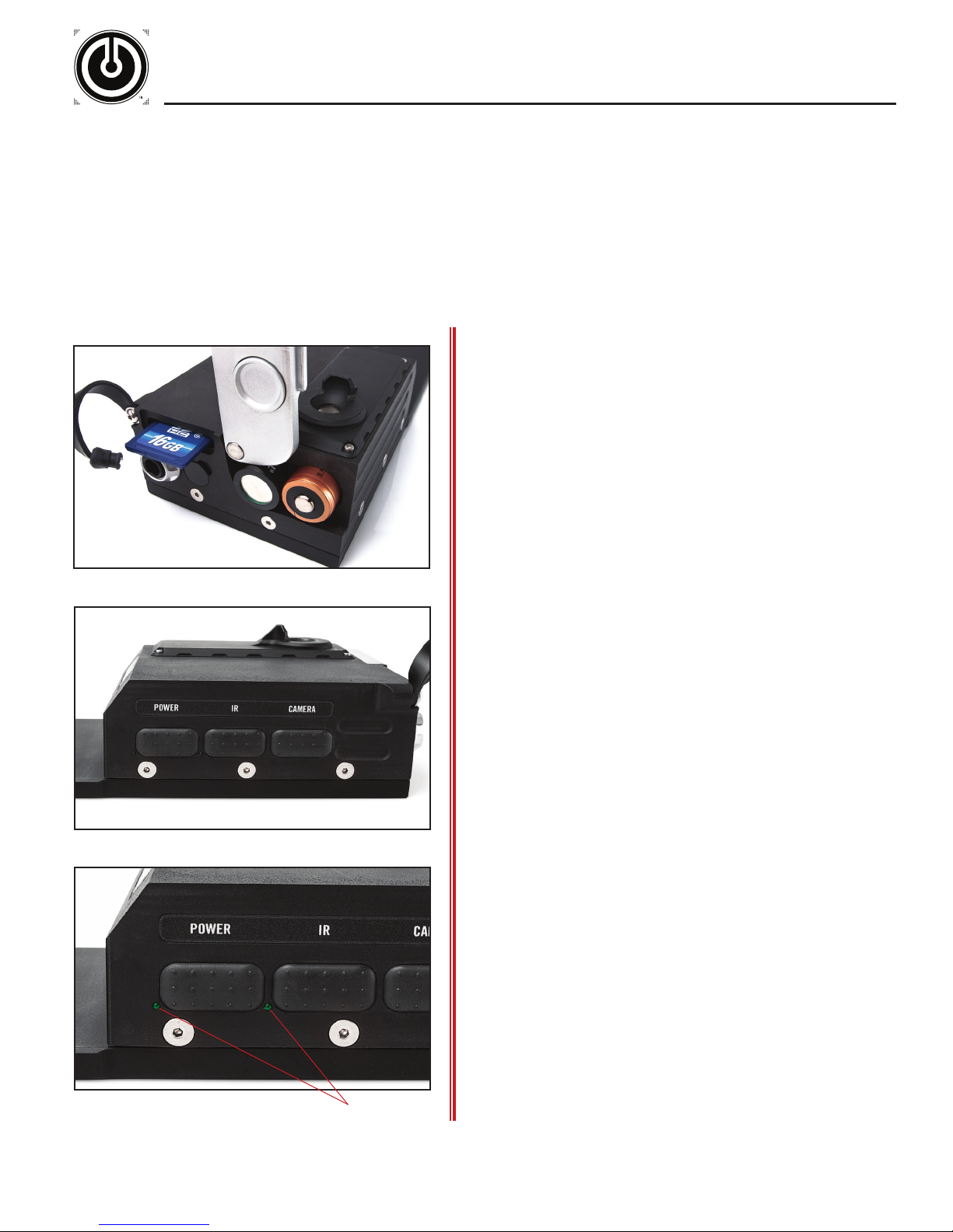
• The diagrams below demonstrate proper battery installation and power-up for the UDC 360 Under Door Camera.
5
» Battery Compartment & Power-Up Procedure:
The UDC 360 (left) requires four 3V Lithium batteries for
operation. Use the battery orientation diagram adhered to the
UDC 360 for reference.
NOTE: For SD card recording, ensure the SD card is inserted
before powering ON the UDC 360.
The power switch for the UDC 360 is a push button located on
the side of the unit. The picture (left) identifies the UDC 360
power button. Fully depress the power button to power ON and
OFF the UDC 360.
* Always remove batteries when not in use
Immediately after the UDC 360 is powered ON the LED indicator
will illuminate a solid blue for approximately 8-10 seconds while
the system initializes. Once the power-up phase is complete
the LED indicator will illuminate a solid green indicating full
operational use (If no SD card is inserted, the LED indicator
will flash red).
Tactical Electronics & Military Supply
NOTE: When the UDC 360 is powered ON all IR LEDS are
powered OFF by default.
To power OFF the UDC 360, hold down the power button for 3
seconds to begin power down cycle - when the LED illuminates
blue release the power button and the unit will power OFF
within 5 seconds.
NOTE: DO NOT open the battery door before powering OFF the
UDC 360. Failure to properly power OFF the unit will result in
loss of recorded files.
» Battery Life Indicator:
The LED power indicator will flash red and green to indicate low
battery power.
As battery life continues to diminish the LED indicator will
illuminate solid red. After the LED illuminates solid red the
unit will shut down within 10 minutes.
LED indicators
When battery life is critical the LED indicator will illuminate
solid blue. Once this occurs the UDC 360 will only remain
ON for 10-15 seconds while the system shuts down to protect
recorded video on the SD card.
Page 6
UDC 360 OPERATION
OPERATION AND SUPPORT PUBLICATION
6
» Operation:
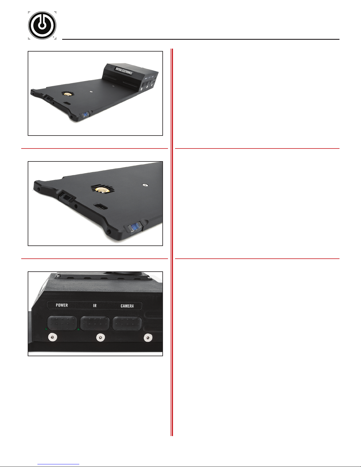
The UDC 360 Under Door Camera is shown (left) in proper
operating position on a flat surface as if it were being slid under
a do o r.
» Insertion Panel:
The distal tip of the UDC 360 houses both the forward and
upward camera lenses, the IR flood illuminator, and the
microphone. The 0.005 lux camera chip is located in the tip of
the insertion panel and slides into the room when the panel is
placed underneath a door.
The unit's IR flood illuminator is mounted on the insertion panel
for enhanced viewing in low-light situations.
» IR LED Modes:
The UDC 360 provides two stages of IR illumination. By default
IR flood illuminator is powered OFF upon every power up of the
UDC 360.
To power ON the IR flood illuminator depress the "IR" button
(shown left). The current state of the IR flood illuminator will be
displayed on the monitor screen.
Remote toggle of IR flood illuminator: Depress the "IR" button
on the Wrist Mounted Monitor Pro or the Handheld Monitor Pro
to remotely turn OFF and ON the IR flood illuminator.
NOTE: Use of the IR LEDs directly affects the battery life of the
unit.
Tactical Electronics & Military Supply
NOTE: The UDC 360 body will become quite warm during use,
especially while using the IR flood illuminator is ON. This is
normal.
Page 7
UDC 360 OPERATION
OPERATION AND SUPPORT PUBLICATION
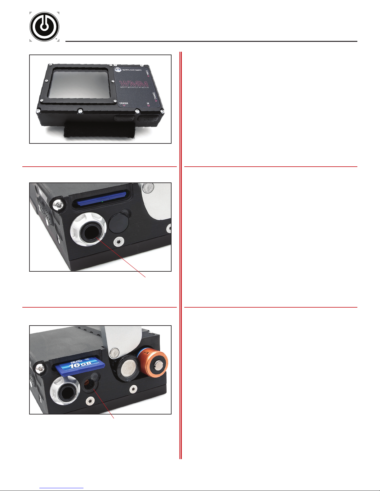
Wrist Mounted Monitor Pro
7
» Wireless Transmission:
Wireless operation of the UDC 360 is very simple. Follow proper
UDC 360 power-up procedure and the unit will automatically
transmit wireless video signals.
Once the UDC 360 is powered ON, the unit immediately begins
transmission of an RF video signal. When a monitor is powered
ON the monitor begins receiving the video signal from the UDC
360. Cycle through the channels on the monitor until a picture
is displayed.
» Hard-Wire Transmission:
The 0.25 inch jack (shown left) is used for hard-wire operation
between the UDC 360 and the Handheld Monitor. Simply power
ON both the UDC 360 and Handheld Monitor, then insert the
male/male cable into the 0.25in jacks on each unit. Hard-wire
operation disables the wireless signal.
0.25in jack
Outgoing channel selector
» Channel Selector:
To determine which channel the UDC 360 is transmitting,
simply power ON both the UDC 360 and monitor. Use the
channel selector button(s) on the monitor to cycle through each
channel until a picture is displayed on screen.
• Shown left is the UDC 360 Outgoing Channel selector.
The UDC 360 will only transmit on channels 1-4. If a channel
outside this range is selected the UDC 360 will not transmit.
Hard-wire, recording, and IR LED functionality will remain
operational.
Tactical Electronics & Military Supply
Page 8
UDC 360 OPERATION
OPERATION AND SUPPORT PUBLICATION
8
» Quad View Camera Selection:
The UDC 360 4-Camera System contains four light sensitive
B/W cameras that provide forward, upward, left, and right
camera views. The forward camera angle provides a forward
view of a room's interior. The upward camera angle provides
a view of the interior side of a door. The left and right camera
angles provide left and right views of a room's interior. All four
cameras are housed within the unit's insertion panel.
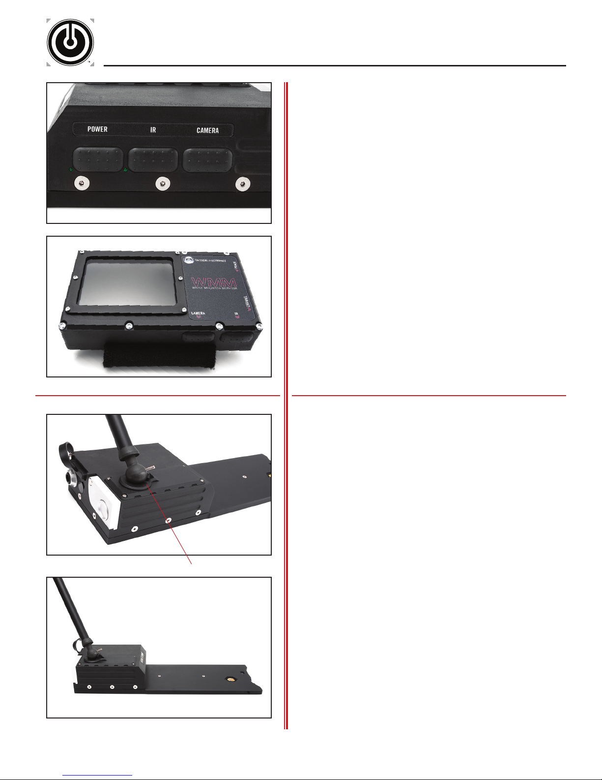
Manual toggle of camera views: Depress the "Camera" button
(located on the side of the UDC 360) to manually toggle
between the forward, upward, left, and right camera views.
Remote toggle of camera views: Depress the "Camera" button
on the Wrist Mounted Monitor Pro or the Handheld Monitor
Pro to remotely toggle between forward, upward, left, and right
camera views.
Remote toggle of IR flood illuminator: Depress the "IR" button
on the Wirst Mounted Monitor Pro or the Handheld Monitor Pro
to remotely turn OFF and ON the IR flood illuminator.
Wrist Mounted Monitor Pro
Push Pole attachment
» Telescoping Push Pole Attachment:
The UDC 360 supports a Telescoping Push Pole. The Push Pole
is designed with a magnetic ball attachment, located at the end
of the pole.
To attach the Push Pole to the UDC 360 simply place the
magnetic ball onto the mount located on top of the UDC 360.
Once the Push Pole is attached the user is capable of placing
the UDC 360 on target and maneuver via the Push Pole.
To detach the Push Pole from the UDC 360, rotate the pole
until the steal pin at the end of the pole pushes away from the
unit and releases from the magnetic mount.
Tactical Electronics & Military Supply
Page 9
UDC 360 OPERATION
OPERATION AND SUPPORT PUBLICATION
9
» SD Card Recording:
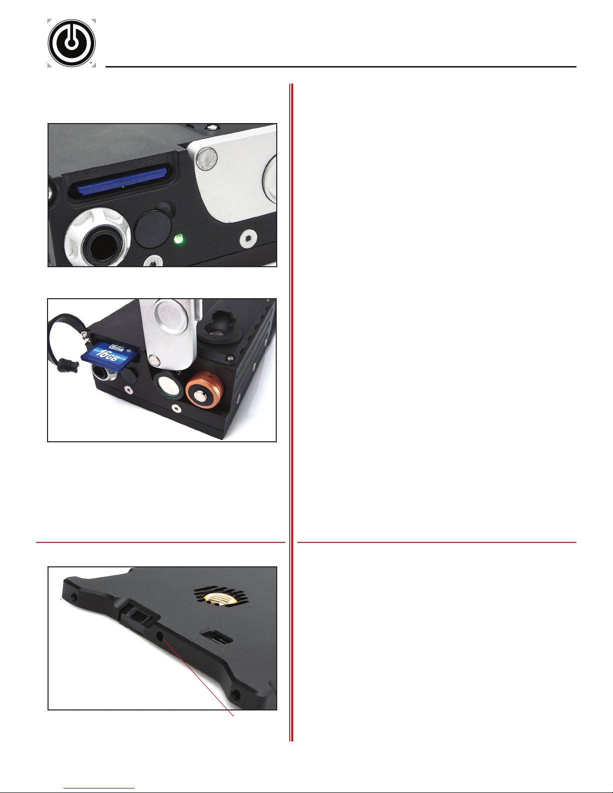
Insert the SD card into the SD card slot with the UDC 360
powered OFF. DO NOT insert or eject the SD card with the
UDC 360 powered ON; otherwise, recorded video files will not
finalize and will become corrupted.
Immediately after the UDC 360 is powered ON, the LED
indicator will illuminate a solid blue for approximately 2-5
seconds while the system initializes. Once the power-up phase
is complete the LED indicator will illuminate a solid green
indicating operational use and proper SD card recording.
If the UDC 360 system indicates a recording error, “REC
ERROR” will display on the monitor(s) in use. If “REC ERROR”
is displayed, power OFF the UDC 360, reinsert the SD card,
and power ON the unit.
The UDC 360 will transmit video without the use of SD card
recording. If the unit is powered ON without an SD card
inserted "REC ERROR" will be displayed on the monitor(s) in
use. The LED indicator on the UDC 360 will also flash red to
indicate no SD card present.
* Push in SD Card to eject
» SD Card Viewing:
To review recorded video files: Power OFF the UDC 360, eject
the SD card, and insert the SD card into an SD card reader on
a co mputer.
All files will be under the folder DCIM\100Media on the SD card.
Recorded files will be listed sequentially in numerical order.
All recorded video files are AVI files, and are easily viewed in
Windows Media Player or VideoLan's VLC Player. AVI files may
also be viewed in QuickTime with the appropriate plug-in.
» Audio:
The UDC 360 houses an omnidirectional microphone and
records audio and video directly to the SD card for post
operational review.
Tactical Electronics & Military Supply
microphone
Page 10
MONITOR OPTIONS
OPERATION AND SUPPORT PUBLICATION
• Tactical Electronics video systems are designed to operate interchangeably with each wireless monitor: Wrist Mounted
Monitor (WMM), Handheld Monitor (HHM), Monocular Micro Viewer (MMV), Heads-Up Display (HUD), Wrist Mounted
Monitor Pro (WMM Pro), or Handheld Monitor Pro (HHM Pro).
• Each monitor is programmed to receive a frequency transmitted directly from the purchased camera system. If multiple
camera systems are in use, the monitors are equipped to receive separate channel frequencies in order to view and
cycle between various Tactical Electronics camera systems.
10
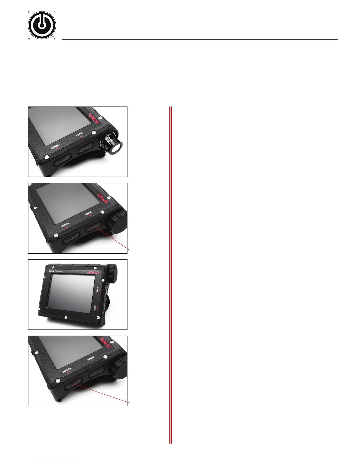
» Wrist Mounted Monitor (WMM)
The Wrist Mounted Monitor is powered by two 3V Lithium
batteries. The batteries are to be inserted positive (+) terminal
first.
The power switch for the Wrist Mounted Monitor (left) is the top
button near the battery cap. Press and hold the power button
for approximately 3 seconds to power “ON” the WMM. The
screen will display the current channel and battery power meter
when the unit is “ON”.
Always remove batteries when not in use.
Power
IM P ORTANT: If lines begin to appear across the screen, the
lines are most likely a sign of LOW BATTERIES.
» WMM Operation
The Wrist Mounted Monitor has a 3.5 inch LCD screen that
displays B/W or color video transmitted from the camera source.
The monitor contains an internal receiver, and when powered
“ON” automatically receives RF video signals from the chosen
camera. The WMM is completely wireless and cannot be hardwired.
» WMM Channel Selection
If multiple camera systems are in use, all monitors are equipped
to receive four separate channel frequencies. Use the channel
selector button in order to view and cycle between multiple
camera systems. When toggling, the current channel will be
displayed on screen.
Tactical Electronics & Military Supply
Channel Selector
To determine a camera’s channel frequency, simply cycle
through each of the four channels until a picture is displayed
on screen.
Page 11
MONITOR OPTIONS
OPERATION AND SUPPORT PUBLICATION
Power
11
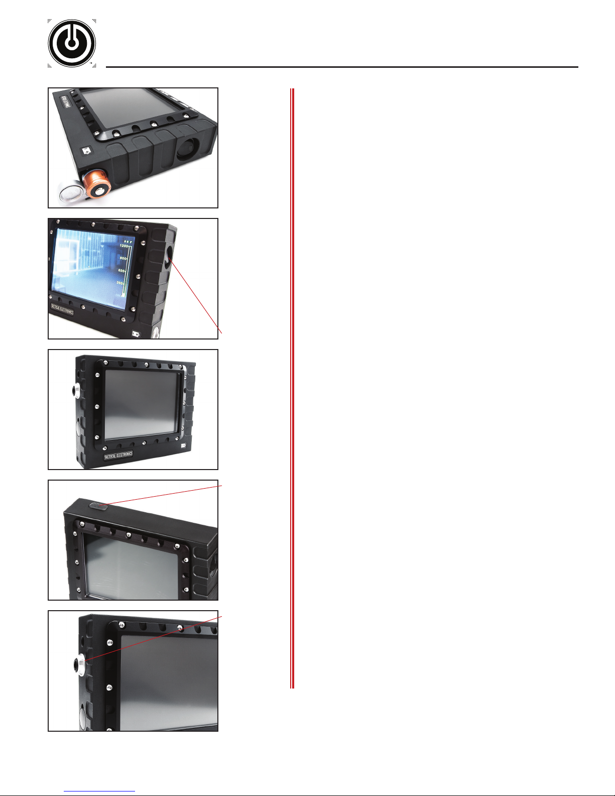
» Handheld Monitor (HHM)
The Handheld Monitor (HHM) is powered by four 3V Lithium
batteries, AC, or vehicle power via cigarette lighter plug. The 3V
Lithium batteries that are to be inserted negative ( - ) terminal
first.
The power switch for the Handheld Monitor (left) is a rocker
type. The green LED is illuminated when the unit is “ON”.
Always remove batteries when not in use.
IM P ORTANT: If lines begin to appear across the screen, the
lines are most likely a sign of LOW BATTERIES.
» HHM Operation
The Handheld Monitor has a 5.0" LCD screen that displays B/W
or color video transmitted directly from the camera source.
Channel Selector
Hard wire jack
It has a built-in receiver and when powered “ON” automatically
receives an RF video signal until a hard-wire is plugged in or the
HHM is powered “OFF”.
» HHM Channel Selection
If multiple camera systems are in use, all monitors are equipped
to receive four separate channel frequencies. Use the channel
selector button in order to view and cycle between multiple
camera systems. When toggling, the current channel will be
displayed on screen.
To determine a camera’s channel frequency, simply cycle
through each of the four channels until a picture is displayed
on screen.
NOTE: Slight adjustments in your viewing angle can greatly
affect the quality of the picture.
» Hard-wire Connection
The Handheld monitor provides a direct hard-wire connection
to compatible camera systems.
Tactical Electronics & Military Supply
NOTE: When working in extreme low light environments hardwire the Handheld Monitor to the camera system (if hardwire option is available with the camera system). A hard-wire
connection provides a slightly brighter picture on the Handheld
Monitor that will be beneficial for low light situations.
Page 12
MONITOR OPTIONS
OPERATION AND SUPPORT PUBLICATION
batter y cap
POWER
12
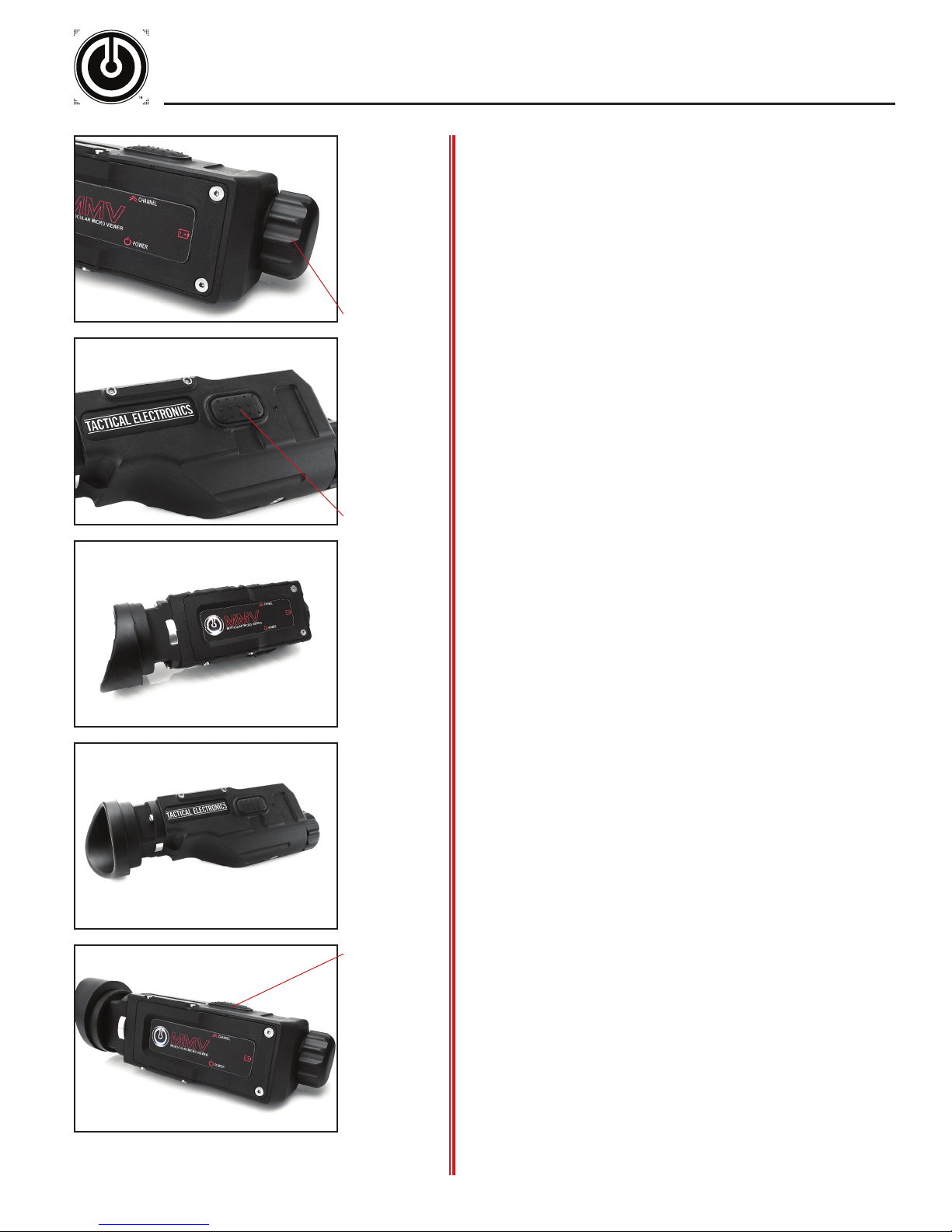
» Monocular Micro Viewer (MMV)
The MMV is powered by one 3V Lithium battery. Unscrew the
battery cap [shown left] to insert the battery. The 3V Lithium
battery is to be inserted according to the battery orientation
diagram on the MMV. Always remove batteries when not in use.
The power button for the MMV (left) is a rubber push button
on the side of the unit. The LED indicator will illuminate green
and the video display will slightly illuminate when the unit is
powered “ON”.
NOTE: The On Screen Display (OSD) will show a flashing battery
icon when the battery is close to critically low levels.
» LED Indicator
• The LED will momentarily light up blue when the unit is
first powered on, then will illuminate solid green.
• The LED will illuminate blue whenever the channel button
is pressed.
• The LED will momentarily illuminate red when the unit is
powering down.
• The LED will illuminate solid red when the battery is low.
channel selector
» Automatic Shutdown
To preserve battery life the MMV will automatically shut off if
the unit is idle for approximately 90 seconds. When the unit
is nearing automatic shutdown the OSD will show a series of
disappearing dots as a countdown timer.
To prevent automatic shutoff: Press the channel button once
to reset shutdown timer, allowing another 90 seconds of video
display. A single press of the channel button will also display
the current channel the MMV is receiving.
» Wireless Video
The MMV has a built-in receiver, and when powered “ON”
automatically receives RF video signals from the chosen camera.
The MMV is completely wireless and cannot be hard-wired.
If multiple camera systems are in use, all monitors are
equipped to receive four separate channel frequencies. Use
the channel selector button in order to view and cycle between
multiple camera systems. When toggling, the current channel
will be displayed on screen. To determine a camera’s channel
frequency, simply cycle through each of the four channels until
a picture is displayed on screen.
Tactical Electronics & Military Supply
NOTE: Any time the channel is changed on the MMV the
shutdown timer is reset. Since the initial press of the channel
button resets the shutdown timer and displays the current
channel, it is necessary to press the channel button more than
once to change channels.
Page 13
MONITOR OPTIONS
OPERATION AND SUPPORT PUBLICATION
13
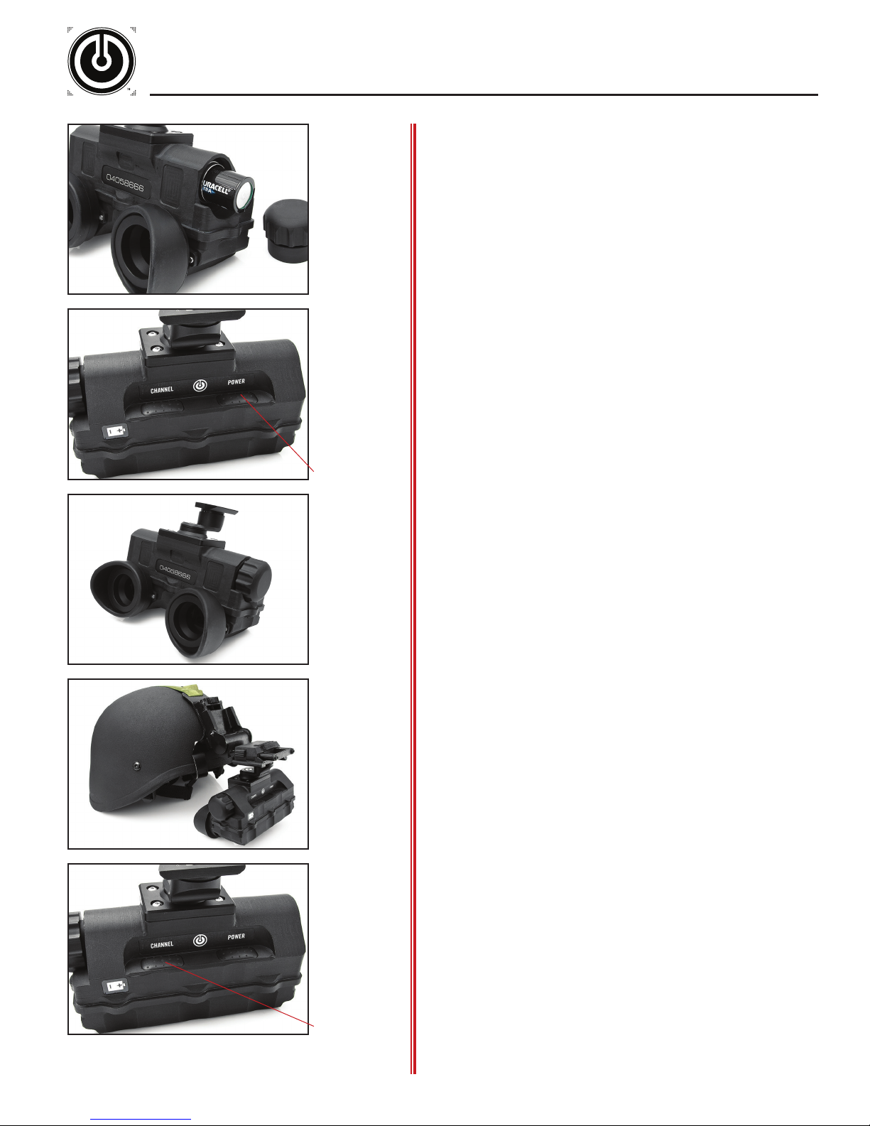
» Heads-Up Display (HUD)
The Heads-Up Display is powered by two 3V Lithium batteries,
The 3V Lithium batteries are to be inserted positive ( + )
terminal first. Always remove batteries when not in use.
The power switch for the Heads-Up Display (left) is a rubber
push button on the front of the unit. The display slightly
illuminates when the HUD is powered “ON”.
To power “OFF” the HUD press and hold the power button.
A red LED in the left eyepiece will illuminate momentarily,
indicating the unit is ready to power down. Release the power
button.
NOTE: The On Screen Display (OSD) will show a flashing battery
icon when the battery is close to critically low levels.
» HUD Operation
POWER
The Heads-Up Display gives the operator the appearance of a
35-inch screen at a 7 foot distance. The HUD displays B/W or
color video transmitted directly from the camera source.
It has a built-in receiver, and when powered “ON” automatically
receives RF video signals from the chosen camera. The HUD is
completely wireless and cannot be hard-wired.
» HUD Mounting
The HUD comes standard with the Wilcox 14001G01 Wilcox
NVG Mounting Shoe. This mounting shoe is compatible with
most Wilcox NVG Mounting Systems.
To mount the HUD to the Wilcox NVG Mount, slide the attached
mounting shoe into the appropriate slot on the NVG Mount until
the HUD system clicks solidly into place.
Detach the HUD from the NVG Mount using the release
mechanism on the NVG Mount.
» HUD Channel Selection
If multiple camera systems are in use, all monitors are equipped
to receive four separate channel frequencies. Use the channel
selector button in order to view and cycle between multiple
camera systems. When toggling, the current channel will be
displayed on screen.
Tactical Electronics & Military Supply
channel selector
To determine a camera’s channel frequency, simply cycle
through each of the four channels until a picture is displayed
on screen.
Note: The first press of the channel selector button will display
which channel the HUD is receiving as well as current battery
power. To change the channel press the channel selector button
again within three seconds.
Page 14
PRO MONITOR OPTIONS
OPERATION AND SUPPORT PUBLICATION
14
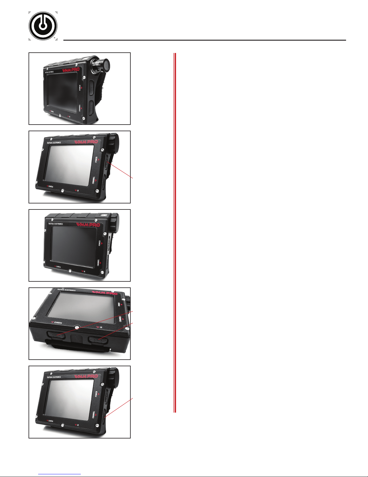
» Wrist Mounted Monitor Pro (WMM Pro)
The Wrist Mounted Monitor Pro is powered by two 3V Lithium
batteries. The batteries are to be inserted positive (+) terminal
first.
The power switch for the WMM Pro (left) is the top button
near the battery cap. Press and hold the power button for
approximately 3 seconds to power “ON” the monitor. The
screen will display the current channel and battery power meter
when the unit is “ON”. Always remove batteries when not in
use.
IM P ORTANT: If lines begin to appear across the screen, the
lines are most likely a sign of LOW BATTERIES.
Power
Camera Toggle
IR Toggle
» WMM Pro Operation
The WMM Pro has a 3.5 inch LCD screen that displays B/W or
color video transmitted from the camera source.
The monitor contains an internal receiver, and when powered
“ON” automatically receives RF video signals from the chosen
camera. The WMM Pro is completely wireless and cannot be
hard-wired.
» Remote Toggle
If the camera system in operation is capable of remote toggling
follow the instructions below to toggle between camera views
and/or IR LED illumination modes.
Remote toggle camera views: Depress the “Camera” button
on the Wrist Mounted Monitor Pro to remotely toggle between
separate camera views.
Remote toggle of IR illumination: Depress the “IR” button on
the Wrist Mounted Monitor Pro to remotely toggle through IR
LED illumination modes.
Tactical Electronics & Military Supply
Channel Selector
» WMM Pro Channel Selection
If multiple camera systems are in use, all monitors are equipped
to receive four separate channel frequencies. Use the channel
selector button in order to view and cycle between multiple
camera systems. When cycling, the current channel will be
displayed on screen.
To determine a camera’s channel frequency, simply cycle
through each of the four channels until a picture is displayed
on screen.
NOTE: Slight adjustments in your viewing angle can greatly
affect the quality of the picture.
Page 15
PRO MONITOR OPTIONS
OPERATION AND SUPPORT PUBLICATION
15
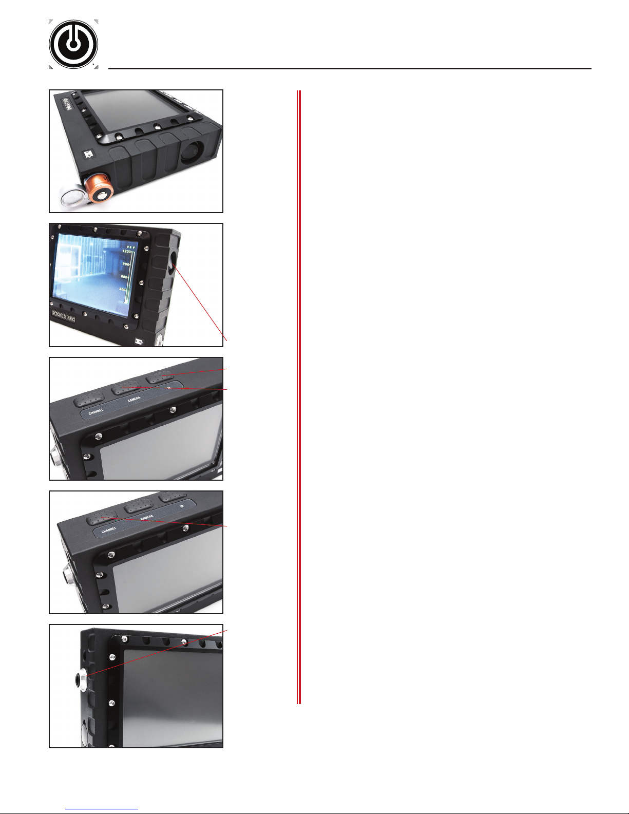
» Handheld Monitor Pro (HHM Pro)
The Handheld Monitor Pro (HHM Pro) is powered by four 3V
Lithium batteries, AC, or vehicle power via cigarette lighter
plug. The 3V Lithium batteries that are to be inserted negative
( - ) terminal first.
The power switch for the HHM Pro (left) is a rocker type. The
green LED is illuminated when the monitor is “ON”. Always
remove batteries when not in use.
IM P ORTANT: If lines begin to appear across the screen, the
lines are most likely a sign of LOW BATTERIES.
The monitor contains an internal receiver and when powered
“ON” automatically receives an RF video signal until a hardwire is plugged in or the HHM Pro is powered “OFF”.
» Remote Toggle
Power
IR Toggle
Camera Toggle
Channel Selector
Hard wire jack
If the camera system in operation is capable of remote toggling
follow the instructions below to toggle between camera views
and/or IR LED illumination modes.
Remote toggle camera views: Depress the “Camera” button on
the Handheld Monitor Pro to remotely toggle between separate
camera views.
Remote toggle of IR illumination: Depress the “IR” button on
the Handheld Monitor Pro to remotely toggle through IR LED
illumination modes.
» HHM Channel Selection
If multiple camera systems are in use, all monitors are equipped
to receive four separate channel frequencies. Use the channel
selector button in order to view and cycle between multiple
camera systems. When cycling, the current channel will be
displayed on screen.
To determine a camera’s channel frequency, simply cycle
through each of the four channels until a picture is displayed
on screen. NOTE: Slight adjustments in your viewing angle can
greatly affect the quality of the picture.
Tactical Electronics & Military Supply
» Hard-wire Connection
The Handheld Monitor Pro provides a direct hard-wire
connection to compatible camera systems. NOTE: When
working in extreme low light environments hard-wire the HHM
Pro to the camera system (if hard-wire option is available with
the camera system). A hard-wire connection provides a slightly
brighter picture on the monitor that will be beneficial for low
light situations.
Page 16
SPECIFICATIONS
OPERATION AND SUPPORT PUBLICATION
SPECIFICATIONS
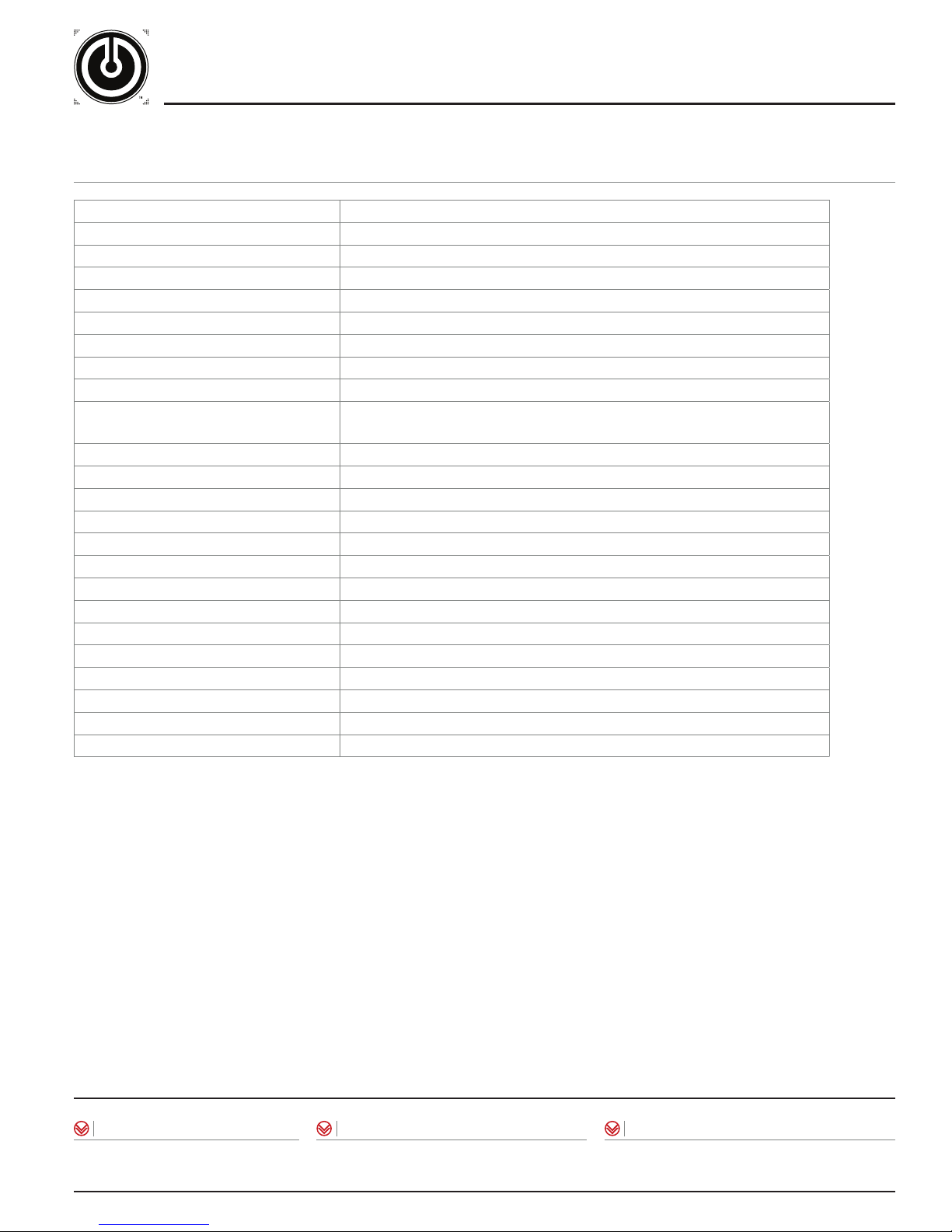
CAMERAS: Forward / Upward / Left / Right facing cameras
WEIGHT: 17.06oz
DIMENSIONS (L X W X H): 9.75in x 3.30in x 1.66in
POWER SUPPLY: Four 3V Lithium batteries (CR123A type)
RUNTIME: 1.25+ hours
HOUSING MATERIAL: High-density polyethylene (HDPE), anodized aluminum
OPERATING TEMPERATURE RANGE: -10ºC to +50ºC, 95% humidity
FREQUENCY RANGE: 2.4 to 2.485 Ghz (4 channel system)
TRANSMISSION DISTANCE: 100ft line of sight
COMPATIBLE MONITORS:
CAMERA RESOLUTION: 400 TV lines
CAMERA LIGHT SENSITIVITY: 0.005 lux
CAMERA SENSOR TYPE: Black and White Super-HAD CCD
ILLUMINATION: IR LED Flood Illuminator
INSERTION PANEL: 0.262in thick
PANEL LENGTH: 6.0in long
HARD-WIRE VIDEO OUTPUT: 1/4 inch stereo jack
FIELD OF VIEW: FORWARD CAMERA 68.6° (H) and 47.4° (V)
FIELD OF VIEW: UPWARD CAMERA 46.26° (H) and 32.8° (V)
FIELD OF VIEW: LEFT / RIGHT CAMERAS 68.6° (H) and 47.4° (V)
Wrist Mounted Monitor Pro / Handheld Monitor Pro / Wrist Mounted Monitor /
Handheld Monitor / Heads-Up Display / Monocular Micro Viewer
16
RECORDING SPECIFICATIONS:
STORAGE MEDIA: SDHC memory card (16GB SDHC card included with system)
RECORDING CAPACITY: 16 hours on 16GB SD card (1GB/hour)
©2013 Tactical Electronics and Military Supply, L.L.C. All Rights Reserved.
Product specifications and information are subject to change without notice.
If you encounter any problems with your system, please contact us immediately:
Tactical Electronics
P.O. Box 152
Broken Arrow, OK 74013-0152
(866) 541-7996
TACTICALELECTRONICS.COM
PRODUCTS / EOD T RAINING / R & D / AVIAT ION
DESIGN / ENGINEERING / MANUFACTURING
HEMLOCK FACILITY
2200 NORTH HEMLOCK AVE / BROKEN ARROW, OK / 74012
V: 866.541.7996 / V: 918.249.8326 / F: 918.249.8328
CRUSADER FACILITY
2844 CRUSADER CIRCLE / #100 / VIRGINIA BEACH, VA / 23453
V: 757.689.0476 / F: 757.689.3769
 Loading...