

Page 1
Application:
Taco Zone Sentry Zone Valves can be used in a wide variety of heating and (non condensing) cooling applications,
primarily designed for use with baseboard, fan coils, radiators, convectors, air handlers, heat pumps and radiant
applications. Refer to the Product Specifications section for
choosing the correct style valve for your application.
General Installation Information / Operation:
The Zone Sentry is the most technologically advanced
zone valve ever made. It’s also simple to install and operate. The valve body can be installed in any position and
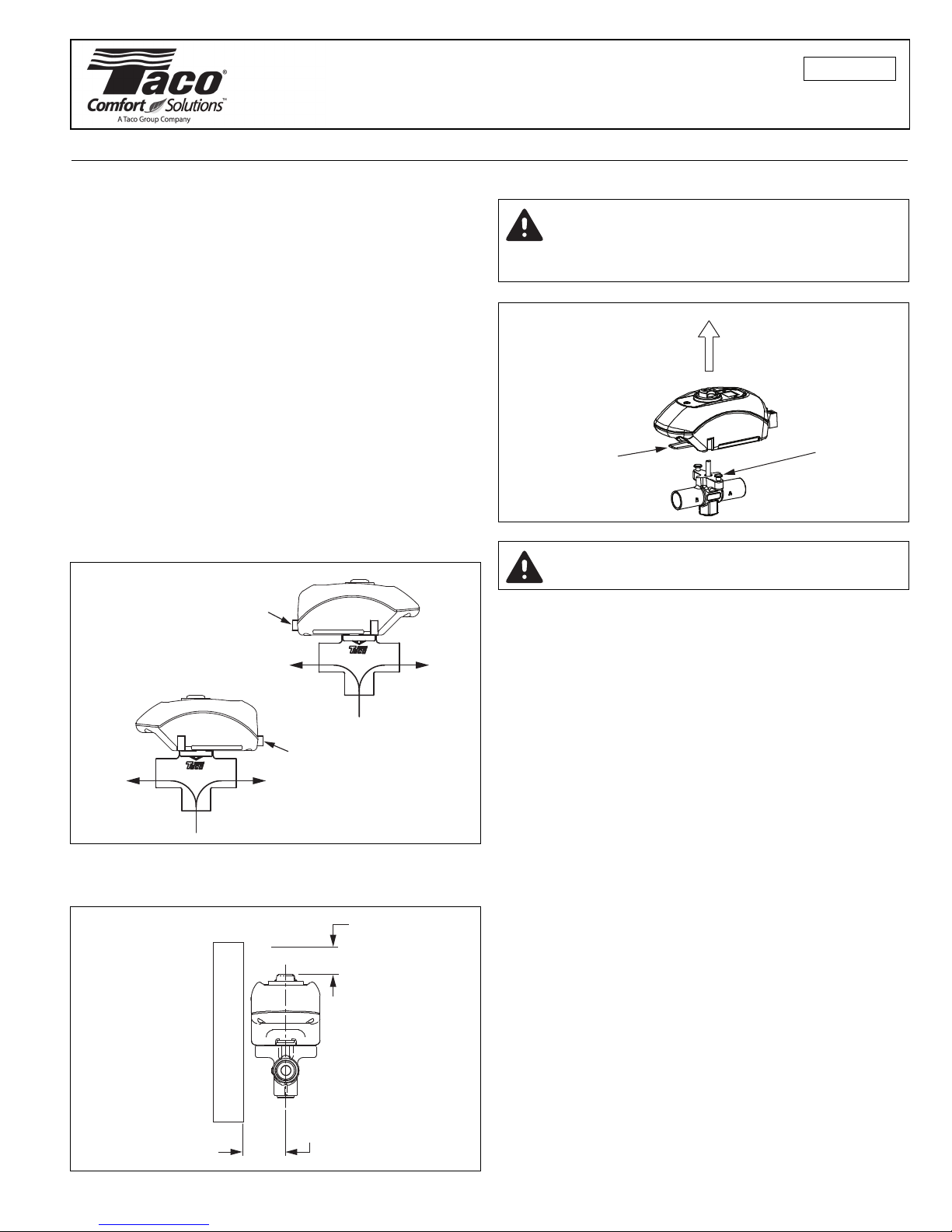
in any orientation. The actuator’s electrical connections
must be mounted over the port that requires flow when
power is applied to the actuator. (See Figure 1.) The back
of the valve makes for a simple, secure and fast wiring
hook-up. A green LED light shows full functionality of the
valve’s operation and thermostat status. Under a no power
situation the manual override button located on the top
of the valve allows the ball to be rotated up to 90°.
Before mounting the body refer to Figure 2 for any clearance requirements.
Use of a solder with a melting point below 600°F is recommended. Do not overheat! Make sure the ball valve is
in the FULL OPEN position to the port that is being soldered. Direct flame tip away from the center of the valve.
Cool valve quickly with a wet rag to prevent overheating.
Solder build-up on the ball valve may prevent proper
opening and closing of the valve.
Valve body may be submerged for leak testing before the
actuator is attached.
Step by Step Valve Installation:
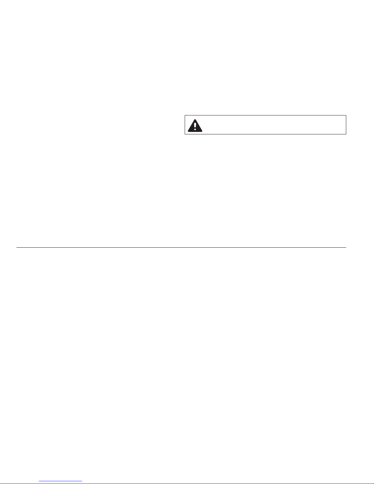
1. Remove actuator from the valve body. Push in and
hold the release clip at the front of the actuator, pull
the actuator away from the body (approx.
3
⁄4"). (See
Figure 3.)
2. Open the valve to the full open position of the first
port to be soldered (port A or B).
3. Clean and prepare the valve and pipe using the
proper techniques required prior to soldering.
4. Fit the valve into the piping system.
5. Solder the port of the valve that you placed in the
full open position, directing the flame away from
the center of the valve.
6. Turn the opening of the valve to the second port to
be soldered. (the opposite port of the one just completed.)
7. Repeat step 5 for the second port.
8. Solder the third port (bottom port). This port is
always in the full open position.
9. Immediately cool the valve with a wet towel.
Instruction Sheet
Zone Sentry 3-way Diverting Valve
102-426
SUPERSEDES: New EFFECTIVE: April 1, 2011
Plant ID# 001-3997
CAUTION: Actuator must be removed from
the valve body before soldering (see
Figure 3). Ball valve must be in the full open
position to the port that is being soldered.
13⁄8" CLEARANCE
3
⁄4" CLEARANCE
W
A
L
L
Figure 2
A
C
B
A
C
B
CALL
CALL
NO CALL
NO CALL
ELECTRICAL
CONNECTION
ELECTRICAL
CONNECTION
Figure 1
L
OCKING
POST
Step 1:
Push in and hold
release clip at the
front of the actuator.
Step 2:
Move actuator away from the
valve body approximately 3⁄4"
to disengage locking posts
and stem.
Figure 3: Operator
Removal
CAUTION: Installation should only be performed by a qualified professional.
Page 2
Installing the Actuator on the Valve Body:
1. Position the actuator so that the “D” shaped valve
stem aligns with the “D” shaped drive cavity in the
operator
2. Slide the actuator onto the valve stem and rotate to
align the valve’s 2 locking posts with the mating
holes in the actuator. Push in the release clip and
slide the actuator down flush to the valve body.
3. Verify that the actuator is locked by pulling it away
from the valve body without pushing in the clip.
(Do not use excessive force.)
Mode of Operation:
1. Upon initial field installation the capacitor requires
a full charge, up to 25 seconds before the valve starts
to turn. Charging time will vary (typically less) during normal operation.
2. When the capacitor is charging the green LED light
will FLASH.
3. Once the capacitor is charged the green LED will
stop flashing but remain ON, at this point the
valve’s actuator will rotate the ball valve. The green
LED will remain ON as long as the thermostat is calling (the unit is powered).
4. Once the thermostat is satisfied the green LED will
turn OFF and the valve will rotate 90° into its normal position or non powered position.
WARNING: Do not use zone valves on indirect
water heaters without a tempering device.
Product Specifications:
Maximum Operating Pressure: 300 PSI (2,100 kPa)
Maximum Shutoff Pressure: 125 PSI (875 kPa)
Fluid Temperature Range: 20° to 240°F, (-7° to 115°C) @ 135°F (57°C) ambient
Service: Closed systems
Optional open system configuration (high oxygen content)
Up to 50% Glycol
Ball Rotation Speed: Full Open to Full Close (90° turn), 5 seconds (after charge time)
Full Close to Full Open (90° turn), 5 seconds (after charge time)
Seat Leakage: Drop-Tight Close-Off
Electrical Rating: 24 VAC, 60 HZ, 0.48 Amps
Do not use more than 12 zone valves per 40VA transformer.
Power Consumption, Charging: 11.4 Watts, 0.48 Amps max
Power Consumption, Power On: 1.44 Watts, 0.06 Amps max
Heat Anticipator Setting: 0.5 Amps
End Switch Rating: 1 Amp @ 24 VAC
Materials of Construction, Actuator:
Body: High Performance Engineered Polymer
Gears: High Performance Internally Lubricated Engineered Polymer
Materials of Construction, Valve:
Body: Forged Bronze
Stem: Brass
Press Ring: Brass
Ball: Brass (Chrome Plated)
Seat: Modified Teflon
®
O-rings: EPDM
Page 3

WARNING: Wiring connections must be
made in accordance
with all applicable electrical
codes.
WARNING: To prevent
electrical shock, dis-
connect electric power
to system at main fuse or circuit breaker box until installation is complete. When a
service switch is installed,
more than one disconnect
switch may be required to
deenergize this device for
servicing.
Zone Sentry Installation and Wiring Diagrams
LED
Motor
Circuit
End Switch
c
w/y
Simplified Internal
Schematic:
Thermostats
Transformer
To “T” Terminals
on Boiler Control
Transformer Relay
T
T
Up to 12 Valves per
40va Transformer
L1 (Hot)
L2
24 v
End Switch
Rh/Rc
w/y
Rh/Rc
w/y
Rh/Rc
w/y
w/y
c
End Switch
w/y
c
End Switch
w/y
c
Typical Zone Sentry Zone Valve Wiring:
NOTE 1: Some power robbing thermostats require the use of a resistor (always use the resistor provided by the thermostat manufacturer with the Zone Sentry). Consult the thermostat instructions for the
resistor installation.
NOTE 2: The plug-in quick connects can be disconnected from the valve actuator for ease of wiring.
Insert the corresponding wire into the quick connects and tighten by turning the screw.
CAUTION: Do not jumper the power/motor (24 VAC) connection terminals, even temporarily. This
may cause damage to the thermostat’s heat anticipator or to the transformer.
Typical Installations for 3-way Valves Normally Closed to the Load
Typical Installations for 3-way Valves Normally Open to the Load
LOAD
LOAD
LOAD
LOAD
SUPPLY
SUPPLY
SUPPLY
SUPPLY
SUPPLY
SUPPLY
SUPPLY
SUPPLY
RETURN
RETURN
RETURN
RETURN
FLOW ON
NO CALL
FLOW ON
NO CALL
FLOW ON
NO CALL
FLOW ON
NO CALL
FLOW ON
CALL
FLOW ON
CALL
FLOW ON
CALL
FLOW ON
CALL
ELECTRICAL
CONNECTION
ELECTRICAL
CONNECTION
ELECTRICAL
CONNECTION
ELECTRICAL
CONNECTION
NOTE for 3-way: Actuator’s power connections must be mounted over the port requiring flow when
power is applied. The valve should always be installed so that the unpowered port is the one with the
highest percentage of time with flow.
Page 4

Taco, Inc. will repair or replace without charge
(at the company’s option) any product or part
which is proven defective under normal use
within three (3) years from the date of start-up or
three (3) years and six (6) months from date of
shipment (whichever occurs first).
In order to obtain service under this warranty, it
is the responsibility of the purchaser to promptly
notify the local Taco stocking distributor or Taco
in writing and promptly deliver the subject product or part, delivery prepaid, to the stocking distributor. For assistance on warranty returns, the
purchaser may either contact the local Taco
stocking distributor or Taco. If the subject product or part contains no defect as covered in this
warranty, the purchaser will be billed for parts
and labor charges in effect at time of factory
examination and repair.
Any Taco product or part not installed or operated in conformity with Taco instructions or which
has been subject to misuse, misapplication, the
addition of petroleum-based fluids or certain
chemical additives to the systems, or other
abuse, will not be covered by this warranty.
If in doubt as to whether a particular substance
is suitable for use with a Taco product or part, or
for any application restrictions, consult the
applicable Taco instruction sheets or contact
Taco at [401-942-8000].
Taco reserves the right to provide replacement
products and parts which are substantially similar in design and functionally equivalent to the
defective product or part. Taco reserves the right
to make changes in details of design, construction, or arrangement of materials of its products
without notification.
TACO OFFERS THIS WARRANTY IN LIEU OF
ALL OTHER EXPRESS WARRANTIES. ANY
WARRANTY IMPLIED BY LAW INCLUDING
WARRANTIES OF MERCHANTABILITY OR FIT-
NESS IS IN EFFECT ONLY FOR THE DURATION
OF THE EXPRESS WARRANTY SET FORTH IN
THE FIRST PARAGRAPH ABOVE.
THE ABOVE WARRANTIES ARE IN LIEU OF ALL
OTHER WARRANTIES, EXPRESS OR STATUTORY, OR ANY OTHER WARRANTY OBLIGATION ON THE PART OF TACO.
TACO WILL NOT BE LIABLE FOR ANY SPECIAL, INCIDENTAL, INDIRECT OR CONSEQUENTIAL DAMAGES RESULTING FROM THE
USE OF ITS PRODUCTS OR ANY INCIDENTAL
COSTS OF REMOVING OR REPLACING
DEFECTIVE PRODUCTS.
This warranty gives the purchaser specific
rights, and the purchaser may have other rights
which vary from state to state. Some states do
not allow limitations on how long an implied warranty lasts or on the exclusion of incidental or
consequential damages, so these limitations or
exclusions may not apply to you.
LIMITED WARRANTY STATEMENT
COMFORT MADE EASY.
®
TACO, INC., 1160 Cranston Street, Cranston, RI 02920 Telephone: (401) 942-8000 FAX: (401) 942-2360.
TACO (Canada), Ltd., 8450 Lawson Road, Unit #3, Milton, Ontario L9T 0J8. Telephone: 905/564-9422. FAX: 905/564-9436.
Visit our web site at: http://www.taco-hvac.com
Printed in USA
Copyright 2011
TACO, Inc.
 Loading...