

Page 1
Please Note: A qualified structural engineer
should be consulted prior to mounting an
antenna on a tower or support structure.
Y113B-140
YAGI ANTENNA
Instruction Sheet
390585 Rev. H
1. Carefully read through the instructions and study the figures before you begin installation of the
antenna.
2. Consult figure 6 and Element Table and Assemble the elements onto the crossarm in their respective
positions as denoted buy their length and letter. DO NOT overtighten the hex-bolts securing the
elements.
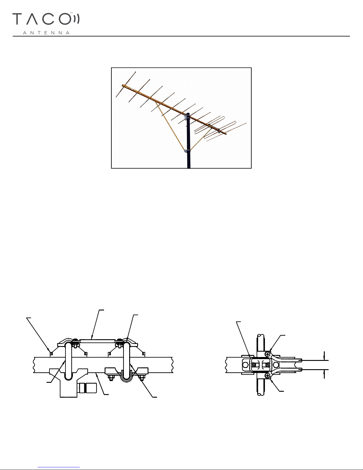
3. Next assemble the feedlines connecting dipole elements C and D as shown using feedline clamps and
10-32 x 5/8 in. screws. Attach feedlines to top of feedline clamps with a centre to centre spacing of
11/16 in. (See Figures 1 and 2)
4. Disregard any unmarked holes on crossarm. Crossarm can be used for other models.
HEX HEAD SCREW
1/4-20 UNC X 2 1/4 in.
(5.72 cm) LONG
FEEDLINE
FEEDLINE CLAMP
PLASTIC INSULATOR
ROUND HEAD SCREW
#10-32 UNF X 5/8 in.
(1.59 cm) LONG
DIPOLE "D"
CROSSARM
Figure 1 Figure 2
11/16 in. (1.75 cm)
FEEDLINE CLAMP
DIPOLE "C"
Page 2
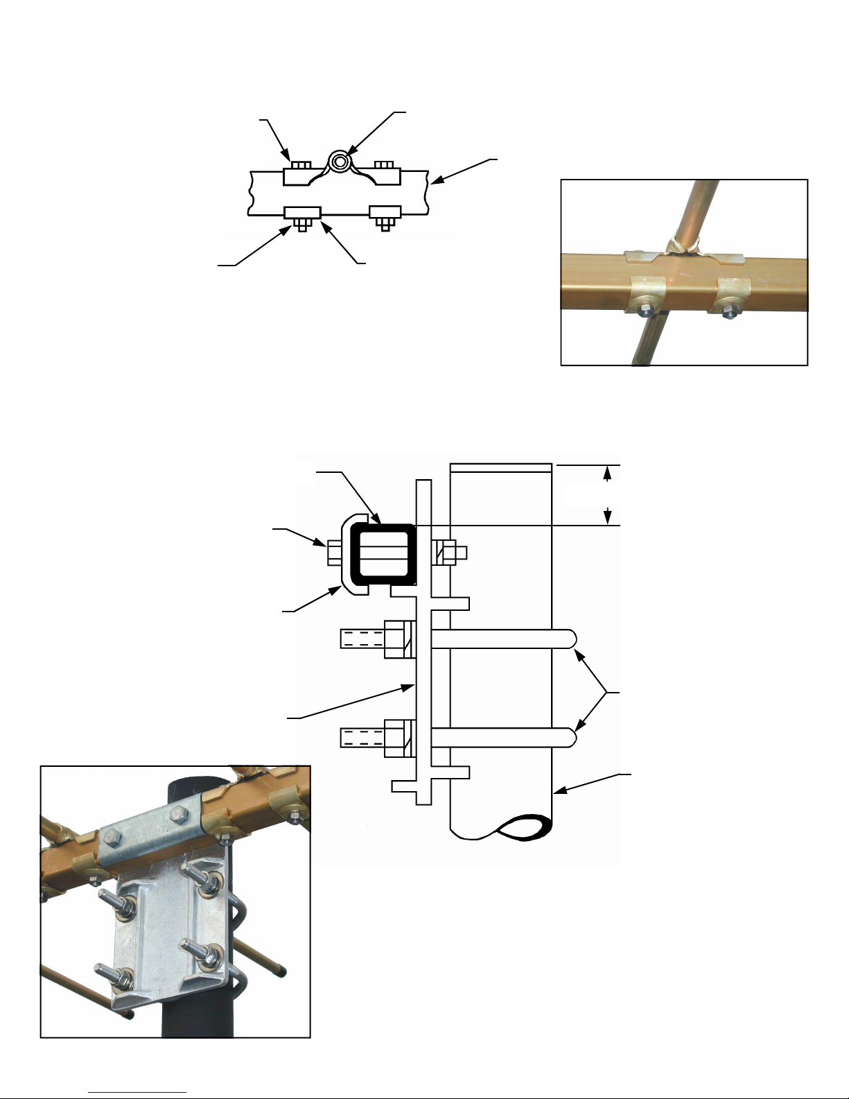
The Parasitic Elements are mounted onto the crossarm at their respective locations, with 2 ” long,
1/4” Bolts, Reinforcing Clips, Lockwashers and Nuts as shown in Figure 3.
HEX HEAD SCREW
1/4-20 X 2 in.
(5.72 cm) long
LOCKWASHER & NUT
ELEMENT
CROSSARM
REINFORCING
CLIP
Figure 3
The antenna main Mounting Clamp is assembled to the crossarm at the holes, perpendicular to the
element holes, with 2¼” long, 3/8” diameter Hex Head Bolt as shown in Figure 4.
CROSSARM
2 in.(5.08 cm) approx.
HEX HEAD SCREW
3/8-16 X 2¼ in.
(5.72 cm) long
REINFORCING CLAMP
MOUNTING PLATE
U-BOLTS 3/8 in. (.95 cm) DIA.
MAST
Figure 4
Page 3

REINFORCING CLIP
1/4” x 2 1/4” HEX
HEAD BOLT
CROSSARM
BRACE
3/8” DIA U-BOLT
MAST
BRACE
CHANNEL
Figure 5
The antenna Braces are assembled to the crossarm at their marked holes 1 or 2 (perpendicular to the
element holes) with 1/4” x 2 1/4” Hex Head Bolts, Reinforcing Clip, Washer, Lockwasher and Hex
Nut. Opposite ends are assembled to the channel and 3/8” U-Bolt, Washer, Lockwasher and Hex Nut
assembly as shown in Figure 5.
SAFETY PRECAUTIONS
1. To protect your antenna and equipment from lightning damage, you should use a lightning arrestor. Attach the
lightning arrestor to the downlead at the point where it enters the building. Drive a ground rod at least 4 feet
into the ground. Use ground wire to connect the antenna mast and the lightning arrestor to the ground rod.
2. Keep antenna and downlead a safe distance from any power lines.
Page 4

A
A
A
FRONT
This label is at the front
A
A
A
A
A
B
C
D
E
BACK
Brace #2
Brace #1
Figure 6
ELEMENT NO. QUANTITY ELEMENT LENGTH
A
B
C
D
E
8 30.00 in
1 32.00 in
1 37.00 in
1 40.00 in
1 50.00 in
29 Sharp Rd, Box 1206
Brantford, Ont., Can., N3T 5L8
www.wadeantenna.com
 Loading...