

Page 1

INSTRUCTION BOOKLET
Y102B-150V
Vertical YAGI ANTENNA
Please Note: A qualified structural engineer should be
consulted prior to mounting an antenna
on a tower or support structure.
www.tacoantenna.com
30377002 Rev. C
Page 2
1-SAFETY PRECAUTIONS
To protect your antenna and receiver from lightning damage, you should
ground your equipment.
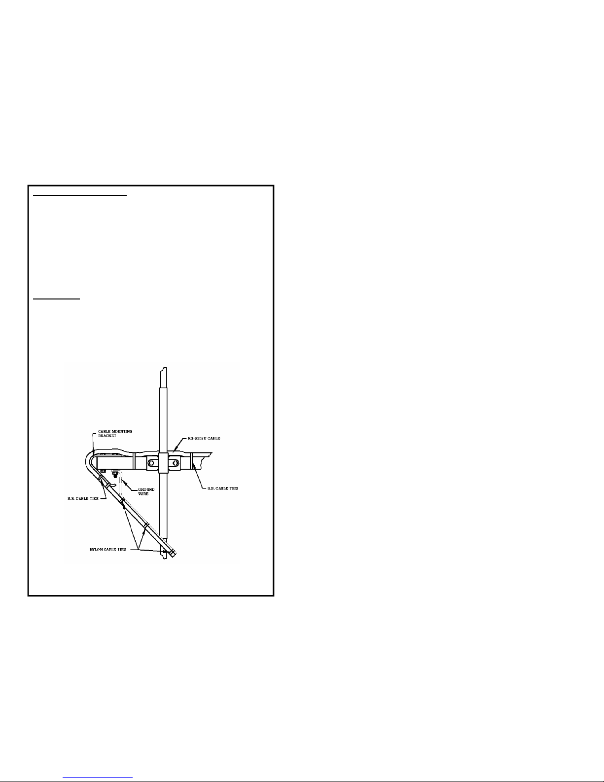
1. To ground the antenna attach a ground wire under the nut of the 1/420 x 2¼ in. long hex head screw at the end of the crossarm see Figure
7. Use nylon cable ties (not provided) to fasten the ground wire to RG213/U cable. Run the ground wire along the RG-213/U to a ground
rod, driven at least 4 feet into the ground.
2. Keep the antenna and cable a safe distance from any power lines.
2-DOWNLEAD
1. Recommended cable is RG-213/U.
2. Thread the connector onto the dipole fitting.
3. Use provided S.S. cable ties to secure the cable to side of the
crossarm.
4. Lay the cable around the cable mounting bracket and use cable ties to
attach it to base of the mast. See Figure 1.
1
FIGURE 1
Page 3

3-ANTENNA ASSEMBLY
The dipoles and elements are match marked to the supporting crossarm.
The dipole insulators and parasitic elements mount to the same side of the
crossarm.
1. Next, starting with dipoles “C” assemble dipoles “C” and “D” to their
marked locations on the crossarm as shown in Figure 2.. Use the 1/4-20
x 2 1/4” hex head screws.
2. The feedlines connecting the dipoles “C” and “D” are attached as shown
in Figure 3 using the supplied feedline clamps and the #10-32 x 5/8” long
round head screws. The feedlines must have a center to center spacing of
3/4” as shown in Figure 3. Attach the feedlines to the top of the feedline
clamps. There must be bare metal to metal contact between the feedlines
and the dipoles.
FIGURE 1
FIGURE 3
2
FIGURE 2
Page 4

3. The parasitic elements are mounted onto the crossarm at its match marked location with 1/4-20 x 2 1/4” long hex head screws, as shown in
Figure 3. Use a reinforcing clip at each screw location.
4-ANTENNA MOUNTING
The antenna mounting clamp is assembled to the crossarm at the un marked holes between the fifth and sixth parasitic element from the front
of the antenna.
1. Assemble the mounting casting to the dipole-fitting side of the crossarm
as shown in Figure 4, using the mounting clamp and the
3/8-16 x 2¼” long hex head screws.
2. Loosely assemble the two 3/8” diameter U-bolts into the mounting
casting.
3. Secure the capped end of the dielectric mast (supplied) so that the
top is a couple of inches above the crossarm.
FIGURE 4
CROSSARM
HEX HEAD SC REW
3/8-16 UNC X 2¼ IN.
(5.72 CM) LONG
MOUNTING CLAMP
MOUNTING CASTING
2 IN. (5.08 CM)
APPROX.
3/8 IN. (.95 CM) DIA.
U-BOLTS
DIELECTRIC MAST
FIGURE 5
CROSSARM
BRACE HEX HEAD SCREW
1/4-20 UNC X 2 1/4 “.
(5.08 CM) LONG
BRACE PLATE
5-BRACE ASSEMBLY
The crossarm brace is attached to the mast side of the crossarm
(see Figure 5) using eight 1/4-20 x 2 1/4” long hex head screws.
6-MOUNTING ASSEMBLY
1. Install 6 Clamping Bolts and Hex Nuts to the antenna base per Fig.1.
2. Slide the Antenna Base onto the Mounting Mast.
3. Tighten the Clamping Bolts while keeping antenna plumb and centered on
the Mounting Mast.
4. Tighten Hex Nuts against the antenna base.
FIGURE 6
ANTENNA BASE
FIGURE 3
CROSSARM
HEX HEAD S CREW
1/4-20 UNC X 2 1/4 IN.
(5.72 CM) LONG
ELEMENT “A”
“B”, or “E”
REINFORCING
CLIP
3 4
CLAMPING BOLTS
HEX NUTS
MOUNTING MAS T
 Loading...