

Page 1
Please Note: A qualified structural engineer
should be consulted prior to mounting an
antenna on a tower or support structure.
Instruction Sheet
30377001 Rev. H
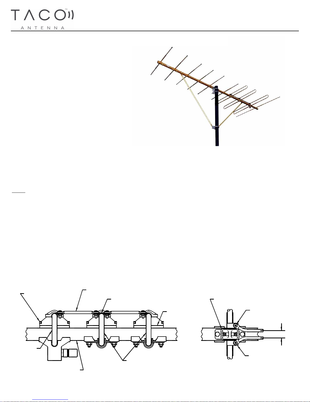
TACO RUGGEDIZED YAGI ANTENNA
FOR MODELS:
Y81-A, -2, -3.
Y-101-65, -4, -B, -5, -6, -C, -FM, -D,-H, -E.
Y-102B-F, -G, -120, -130, -150.
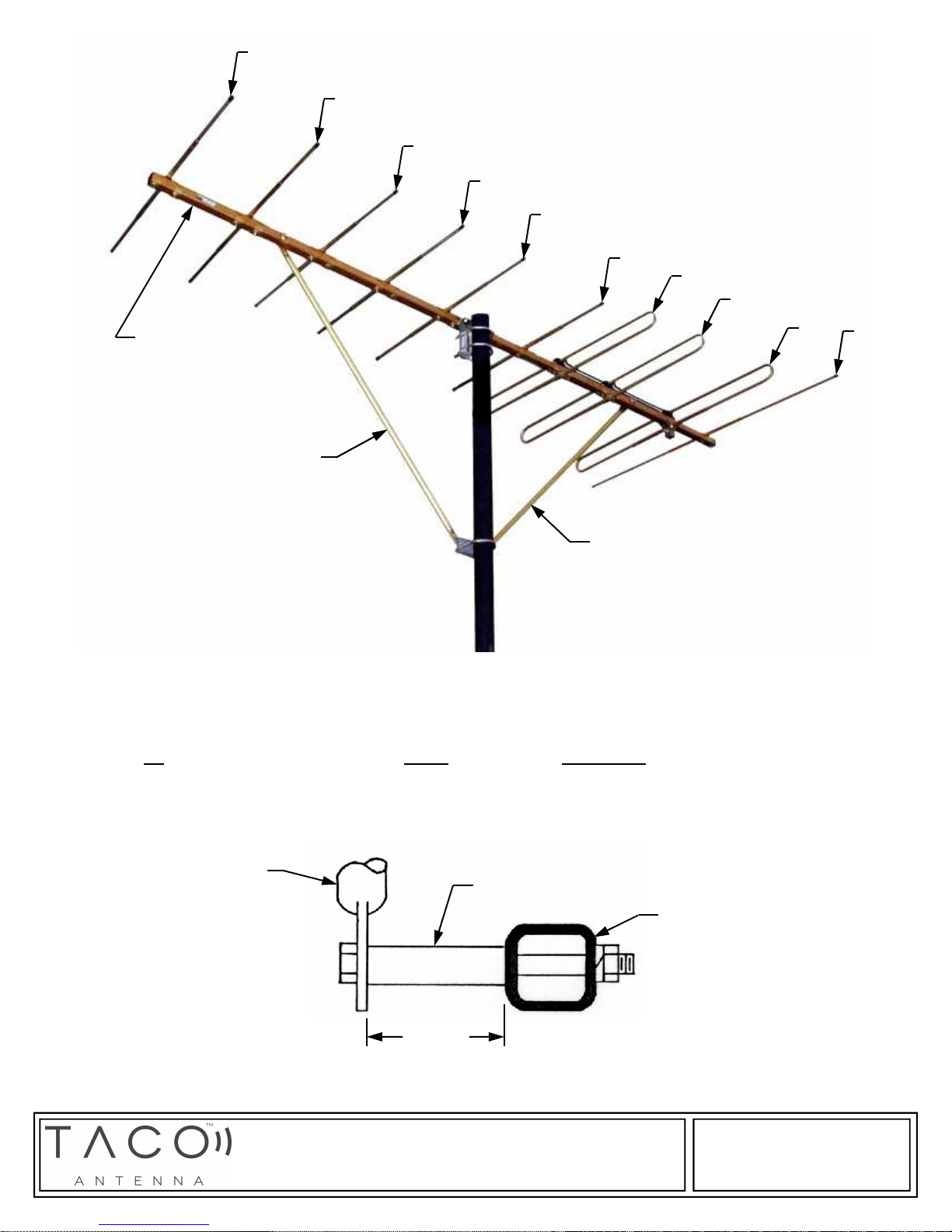
The Yagi dipoles and parasitic elements are all identified with a letter i.e. A, B, C, D and E. These markings will be
found on the crossarm indicating the location these elements are to be assembled on the crossarm (See Figure 6).
The antenna main mounting clamp holes are located in the crossarm perpendicular to the element holes. The dipole
insulators and parasitic elements mount to the same side of the crossarm.
Note: All Y-101 and Y-81 series Yagi have a two-piece crossarm. The antenna main mounting clamp is used to
assemble the two halves together and for this purpose four (4) 3/8” Dia. Bolts are supplied.
Start with the director element and the dipole elements and assemble them to their marked locations on the
crossarm as shown in Figure 1. Shims are supplied with Y-101-65, -4, -B, -5, -6, -C, -FM, -D,-H, and –E, to be
assembled with the dipole elements as shown in Figure 1. The dipoles are attached with 2 ¼ or 2 ½ (for models with
shims) inch long 1/4 inch bolts.
Next assemble the feedlines connecting the dipole elements as shown using feedline clamps and 5/8 inch long
10-32 screws (See Figure 2). Attach feedlines at dipoles to top of clamps with a centre-to-centre spacing of 3/4 inch
(See Figure 2).
HEX HEAD SCREW
1/4-20 UNC X 2 1/4 or 2 1/2 in.
(5.72/6.35 cm) LONG
DIPOLE
CROSSARM
NOTE:
Shims are supplied with Y-101-65, -4, -B, -5, -6, -C, -FM, -D,-H, and –E only.
FEEDLINE
FEEDLINE CLAMP
DIPOLE
FIGURE 1 F
SHIM (see note)
PLASTIC INSULATOR
ROUND HEAD SCREW
#10-32 UNF X 5/8 in.
(1.59 cm) LONG
3/4 in. (1.91 cm)
FEEDLINE CLAMP
IGURE 2
Page 2
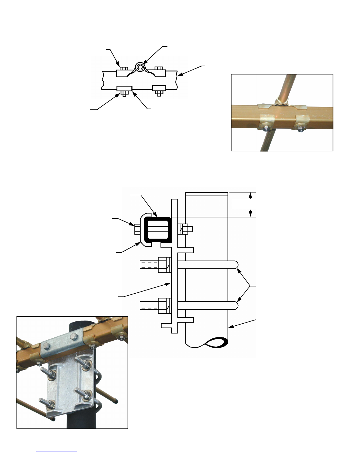
The Parasitic Elements “A”, “B”, and “E” are mounted onto the crossarm at their match marked
locations, with 2 ¼” long, 1/4” Bolts, Reinforcing Clips, Lockwashers and Nuts as shown in Figure 3.
HEX HEAD SCREW
1/4-20 UNC X 2 ¼ in.
(5.72 cm) LONG
LOCKWASHER & NUT
ELEMENT
CROSSARM
REINFORCING
CLIP
FIGURE 3
The antenna main Mounting Clamp is assembled to the crossarm at the unmarked holes (perpendicular
to the element holes) with 2¼” long, 3/8” diameter Hex Head Bolt as shown in Figure 4.
CROSSARM
2 in.(5.08 cm) approx.
HEX HEAD SCREW
3/8-16 UNC X 2¼ in.
(5.72 cm) LONG
REINFORCING CLAMP
MOUNTING PLATE
3/8 in. (.95 cm) DIA. U-BOLTS
MAST
FIGURE 4
Page 3

The antenna Braces are assembled to the crossarm at the unmarked holes (perpendicular to the
element holes) with 1/4” x 2½” Hex Head Bolts, Reinforcing Clip, Washer, Lockwasher and Hex Nut.
The opposite ends of the braces are assembled to the mast (mounting pipe) using the channel and 3/8”
U-Bolt, Washer, Lockwasher and Hex Nut assembly as shown in Figure 5.
REINFORCING CLIP
1/4” x 2½” HEX
HEAD BOLT
CROSSARM
BRACE
3/8” DIA U-BOLT
MAST
BRACE
CHANNEL
FIGURE 5
SAFETY PRECAUTIONS
1. To protect your antenna and equipment from lightning damage, you should use a lightning arrestor. Attach the
lightning arrestor to the downlead at the point where it enters the building. Drive a ground rod at least 4 feet
into the ground. Use ground wire to connect the antenna mast and the lightning arrestor to the ground rod.
2. Keep antenna and downlead a safe distance from any power lines.
Page 4
A
A
A
A
A
B
C
C
CROSSARM
D
BRACE
BRACE
E
FIGURE 6
For stacking antennas in an array on a limited frame, the antenna support braces can be inverted or installed going up
at an angle instead of going down at an angle. CAUTION must be used to insure that the
antenna radiators be oriented in spaces identical (in phase condition), therefore to eliminate any interference between brace and antenna, a 2 in. spacer (not supplied) must be installed between antenna
crossarm and brace bars as shown in Figure 7.
BRACE
SPACER (NOT SUPPLIED)
CROSSARM
2.00 in.
FIGURE 7
(See Figure 5 for normal installation)
29 Sharp Rd, Box 1206
Brantford, Ont., Can., N3T 5L8
www.wadeantenna.com
 Loading...