

Page 1
Instruction Sheet
A
X – Pump Block (XPB)
102-202
SUPERSEDES: July 1, 2010
EFFECTIVE: October 1, 2010
Plant ID#: 001-3883
WARNING SYMBOL: THIS SYMBOL INDICATES THE PRESENCE OF HAZARDS WHICH
CAN CAUSE SEVERE PERSONAL INJURY, SUBSTANTIAL PROPERTY DAMAGE OR
EVEN DEATH IF IGNORED.
General
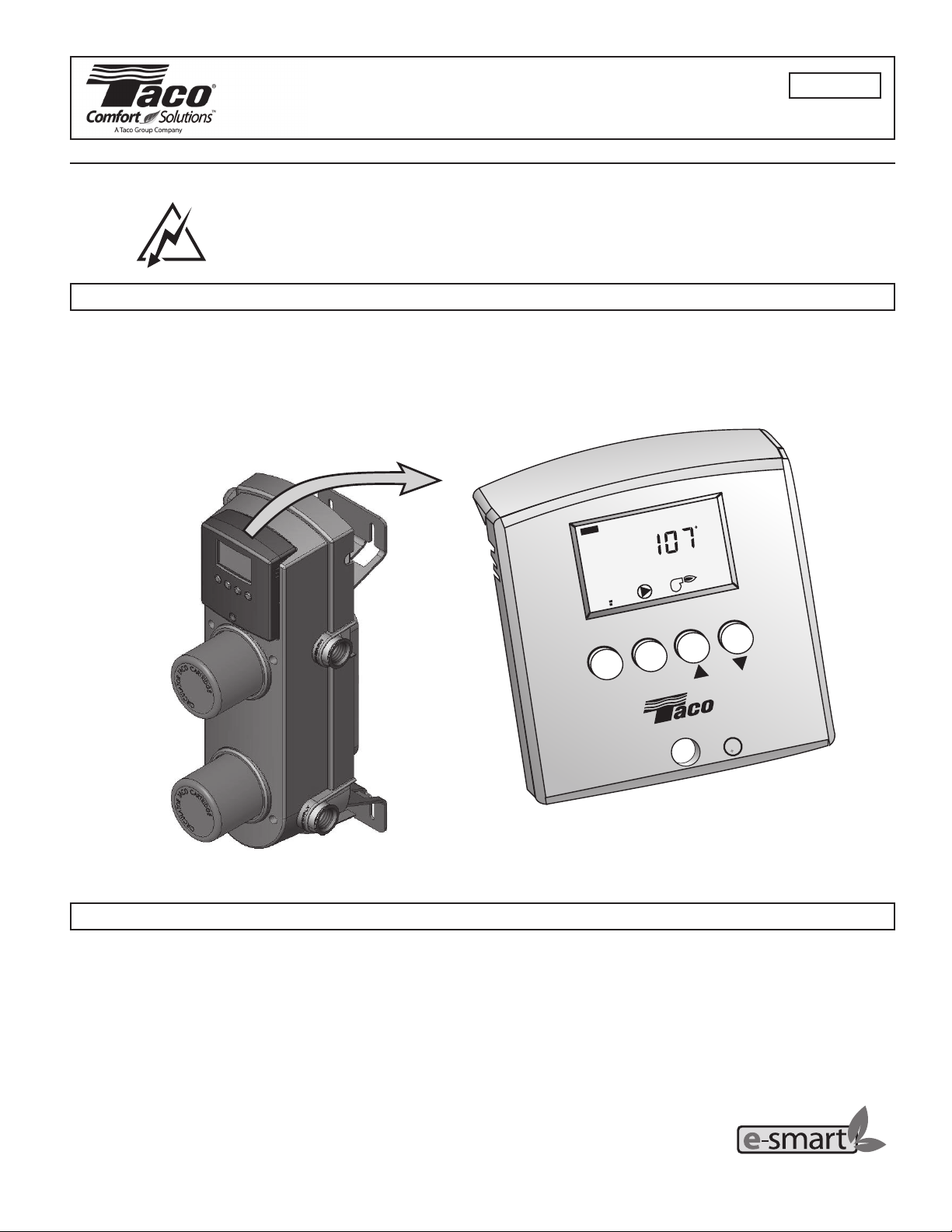
The Taco X – Pump Block (XPB) represents a breakthrough in the design, control and installation of heating systems. The patent
pending design combines a variable speed mixing control (VSMC), heat source circulator, system circulator, and heat exchanger into a
single unit. This combination delivers complete isolation between the heat creation source side of the system (boiler, water heater, etc.)
and the heat delivery side of the system (radiant tubing, glycol based snowmelt, baseboard, etc.). Extremely versatile, the
X – Pump Block can be set up to operate in outdoor reset, setpoint or delta T limiting mode.
VIEW
MIX SUP
%
1
F
DEM
X – PUMP BLOCK (XPB) VARIABLE SPEED MIXING CONTROL (VSMC)
Table of Contents
TYPICAL PIPING ------------------------------------------------ 2
GETTING READY ----------------------------------------------- 3
APPLICATION ---------------------------------------------------- 3
DESIGN PROCEDURE ----------------------------------------- 3
INSTALLATION OF X – PUMP BLOCK ------------------- 4
OUTDOOR RESET MODE ------------------------------------ 5
OUTDOOR RESET SETTINGS ------------------------------ 5
SETPOINT AND DELTA T MODE --------------------------- 6
SETPOINT AND DELTA T SETTINGS --------------------- 7
MENU
PATENT PENDING
ITEM
X - PUMP BLOCK
U
C
TM
XPB-1
L
R
US
HEAT SOURCE OPERATION MODE ---------------------- 7
SET UP OF VARIABLE SPEED MIXING CONTROL -- 8
DISPLAY OPERATION ---------------------------------------- 11
TROUBLE SHOOTING ---------------------------------------- 13
ERROR MESSAGES ------------------------------------------ 14
REPLACING CARTRIDGE ASSEMBLY ------------------ 14
TECHNICAL DATA --------------------------------------------- 15
CLEANING ------------------------------------------------------- 16
LIMITED WARRANTY STATEMENT ---------------------- 16
Taco resource – saving product
1 of 16
Page 2
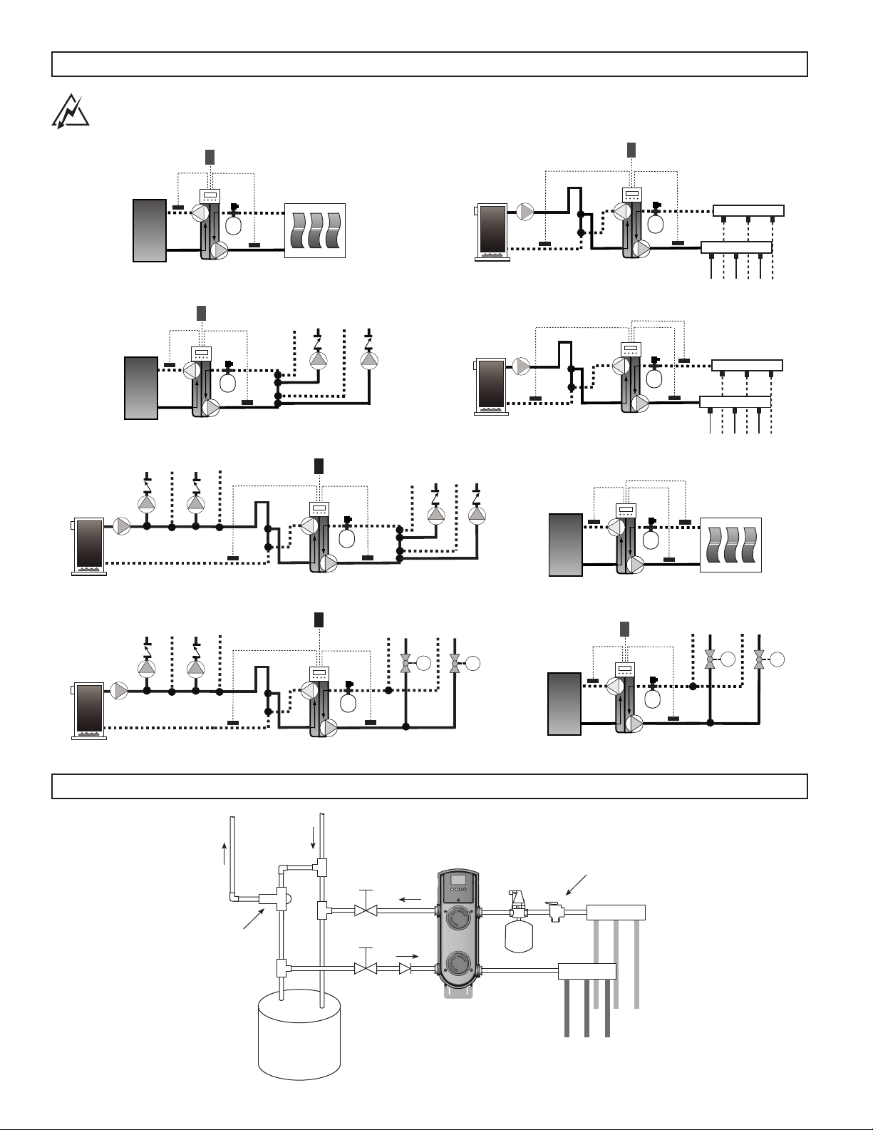
Typical Piping
Warning! Must Install a Pressure Relief Valve and Expansion Tank on Secondary Side
in addition to Units Installed on Primary Side of System.
Outdoor
Sensor
Pressure
Relief
Exp
Tank
Output to
System
Supply
Sensor
HEAT
SOURCE
Return
Sensor
Input from
Heat Source
Outdoor
Sensor
Pressure
Relief
Exp
Tank
Output to
System
Supply
Sensor
Return
Sensor
Input from
Heat Source
Radiant Manifold - Return
Radiant Manifold - Supply
X - Pump Block (XPB)
Outdoor
Sensor
HEAT
SOURCE
Return
Sensor
Input from
Heat Source
Pressure
Relief
Exp
Tank
Output to
System
Supply
Sensor
X - Pump Block (XPB), Multiple Zones - Circulators
Outdoor
Sensor
Pressure
Relief
Exp
Tank
Return
Sensor
Input from
Heat Source
Output to
System
Supply
Sensor
X - Pump Block (XPB), Multiple Temperature System – Circulators
Outdoor
Sensor
M
Return
Sensor
Input from
Heat Source
Pressure
Relief
Exp
Tank
Output to
System
Supply
Sensor
Relief
Exp
Tan k
System
System
Supply
Sensor
System
Return
Sensor
X - Pump Block (XPB), Primary / Secondary Piping
Pressure
Return
Sensor
Input from
Heat Source
Output to
X - Pump Block (XPB), Setpoint Temp with delta T
System
Supply
Sensor
System
Return
Sensor
Return
Sensor
HEAT
SOURCE
Input from
Heat Source
Pressure
Relief
Exp
Tan k
Output to
System
X - Pump Block (XPB), delta T Snow Melt System
Outdoor
Sensor
HEAT
SOURCE
Return
Sensor
Input from
Heat Source
Pressure
Relief
Exp
Tank
Output to
System
Supply
Sensor
M
Radiant Manifold - Return
Radiant Manifold - Supply
M
M
X - Pump Block (XPB), Multiple Temperature System – Circulators and Zone Valves
Typical Installation
Tempering
Valve
Domestic
Hot
Supply
MIX
Hot
C
H
WATER
HEATER
Cold
Cold
Supply
Check
Valve
2 of 16
X-PUMP
BLOCK
X - Pump Block (XPB), Multiple Zones - Zone Valves
Relief
Air
Separator
Valve
Return
Exp.
Tank
RADIANT
SYSTEM
Supply
Page 3
Getting Ready
Ensure that the contents of this package are complete. If any of the contents are missing or damaged, please contact your local Taco
sales representative for assistance.
Contents should include the following:
• One X – Pump Block, preassembled
unit consists of the following parts:
- One Variable Speed Mixing Control (VSMC)
• One Taco Outdoor Sensor
• Two Taco Strap-on Sensors
• One Instruction Sheet
- One Green Enclosure
- Two Casings with Circulators Attached
- One Heat Exchanger
- One Power Cord (6 feet)
Application
The Taco X – Pump Block (XPB) is a complete mixing system with an attached heat exchanger for system isolation. Integral to the unit
is a variable speed heat source circulator, constant speed system circulator, heat exchanger, and the electronics to drive it all. With
only four piping connections needed, the XPB greatly reduces the time and space required for installation. The heat exchanger
provides complete isolation between fluid on the heat source side and the fluid on the system side. The XPB can be set up to operate
as an outdoor reset control, a setpoint control or a delta T limiting control, creating flexibility never seen before in a single unit.
Design Procedure
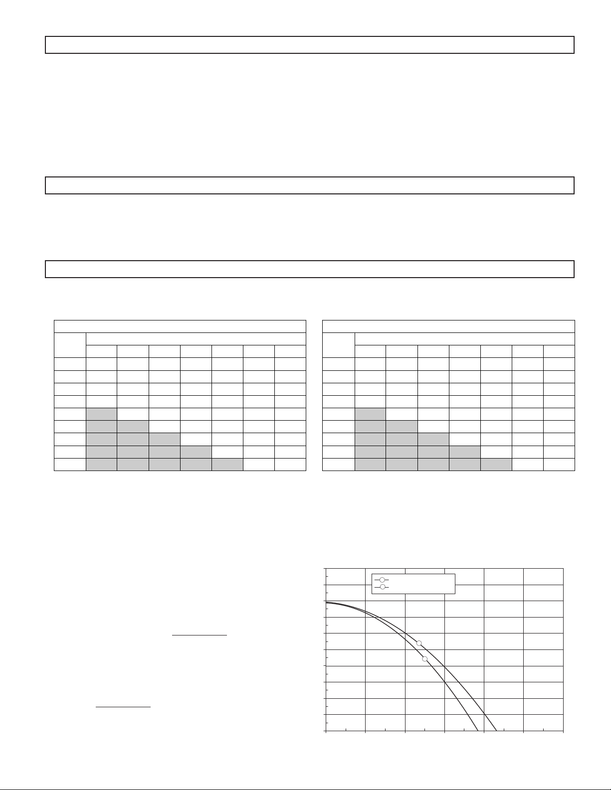
1. Verify BTU capacity of X-Pump Block using charts below.
BTU/H Capacity @ 10 degree Delta T Across System
X-Pump BTU Capacities*
System
Temp.
120/100 130/110 140/120 150/130 160/140 170/150 180/160
70/80 29,900 29,900 29,900 29,900 29,900 29,900 29,900
80/90 29,800 29,800 29,800 29,800 29,800 29,800 29,800
190/100 29,800 29,800 29,800 29,800 29,800 29,800 29,800
100/110 4,500 29,700 29,700 29,700 29,700 29,700 29,700
110/120 5,500 29,600 29,600 29,600 29,600 29,600
120/130 6,000 29,600 29,600 29,600 29,600
130/140 6,500 29,500 29,500 29,500
140/150 7,000 29,400 29,400
150/160 7,500 29,300
* Assuming 6 gpm Flow on Radiant Side of XPB
Heat Source Temperature Range
BTU/H Capacity @ 20 degree Delta T Across System
X-Pump BTU Capacities*
System
Temp.
120/100 130/110 140/120 150/130 160/140 170/150 180/160
60/80 59,900 59,900 59,900 59,900 59,900 59,900 59,900
70/90 59,800 59,800 59,800 59,800 59,800 59,800 59,800
180/100 27,000 59,800 59,800 59,800 59,800 59,800 59,800
190/110 4,500 29,000 59,700 59,700 59,700 59,700 59,700
100/120 5,500 31,500 59,600 59,600 59,600 59,600
110/130 6,000 33,500 59,600 59,600 59,600
120/140 6,500 35,500 59,500 59,500
130/150 7,000 37,600 59,400
140/160 7,500 39,700
Heat Source Temperature Range
2. Using the pump curve located below, ensure that the System Pump of the X – Pump Block will provide adequate head and flow for
the system in which it is to be installed. If flow rate is unknown, then use Equation No. 1 below to determine required flow.
3. Using the pump curve located below, ensure that the Heat Source Pump of the X – Pump Block will provide adequate head and flow
for the system in which it is to be installed. If flow rate is unknown, then use Equation No. 1 below to determine required flow.
4. Use Equation No. 1 to verify flow rates. Example: 25000 BTU
radiant load with supply temperature of 100° and return
temperature of 90°.
EQUATION NO. 1:
Flow Rate (GPM) =
BTU's
500 x delta T
EXAMPLE:
25,000
500 (100 - 90)
= 5 GPM
20
18
16
14
12
10
HEAD (ft)
8
6
4
2
0
024681012
PUMP CURVES
1
SYSTEM SIDE
2
HEAT SOURCE SIDE
1
2
FLOW (gpm)
3 of 16
Page 4
Installation of the X – Pump Block
STEP ONE MOUNTING
1. Mounting position – The X – Pump Block must be mounted in the vertical position with the Variable Speed Mixing Control (VSMC)
located at the top of the X – Pump Block.
2. Mount the X – Pump Block, using the attached brackets, to a solid surface capable of supporting 23.5 pounds.
3. Using four suitable screws or bolts (1⁄4”), fasten the X – Pump Block to the selected location. Ensure that at least two of the mounting
screws are attached to a wall stud or similar surface.
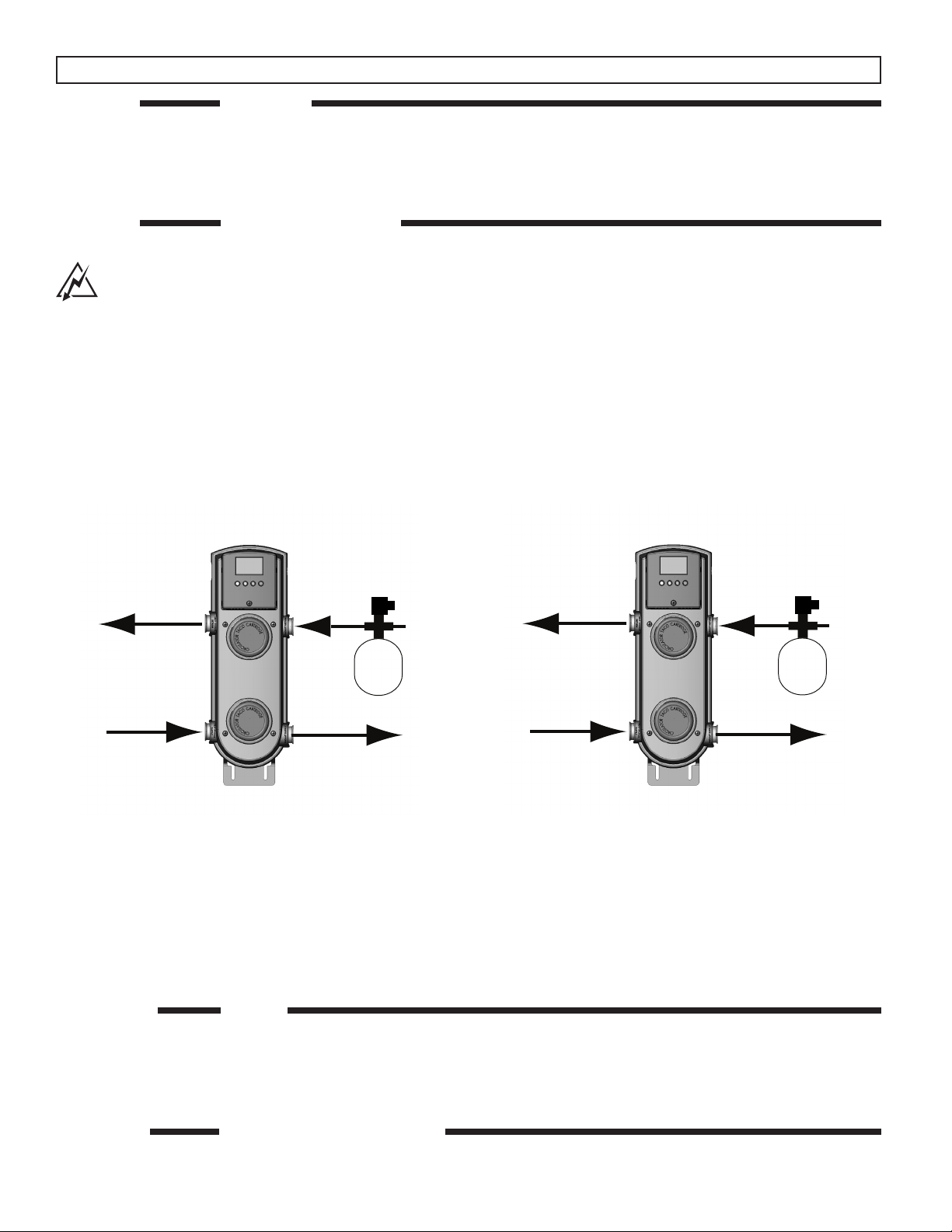
STEP TWO PIPING CONNECTIONS
Warning! Must Install a pressure relief valve and expansion tank on secondary side in addition to units
installed on primary side of system. Note! Heat should never be applied to X – Pump Block connections
or damage to housing and/or electronics may result.
1. Using proper piping practices, connect the supply to the radiant heating system to the Radiant Supply (bottom right hand connection) as indicated on the plastic cover of the X – Pump Block. Ensure that a proper isolation valve is installed.
2. Using proper piping practices, connect the return from the radiant heating system to the Radiant Return (top right hand connection)
as indicated on the plastic cover of the X – Pump Block. Ensure that a proper isolation valve is installed.
3. Using proper piping practices, connect the supply from the heat source to the Heat Source Supply (bottom left hand connection) as
indicated on the plastic cover of the X – Pump Block. Ensure that a proper isolation valve is installed.
4. Using proper piping practices, connect the return to the heat source to the Heat Source Return (top left hand connection) as
indicated on the plastic cover of the X – Pump Block. Ensure that a proper isolation valve is installed.
5. When using a non-condensing heat source as heat source, connect the Heat Source Supply and Heat Source Return lines of the
X – Pump Block to the heat source loop using standard Primary Secondary piping practices.
Pressure
Relief
Exp
Tank
Heat Source
Return
Variable
Flow
Heat Source
Supply
Radiant
Return
Constant
Flow
Radiant
Supply
Pressure
Relief
Exp
Tank
Heat Source
Return
Constant
Heat Source
Supply
Flow
Snow
Melt
Return
Variable
Flow
Snow Melt
Supply
Refer to Page 2 for More Piping Diagrams
When using the X - Pump Block on snow melting systems, it is recommended to switch the system pump motor with the variable
speed pump motor to protect the brazed plate heat exchanger from freezing up.
Follow the instructions for cartridge replacement (page 14) to disassemble the X – Pump.
Unbolt the fixed speed system pump motor (lower) and switch it with the heat source variable speed pump motor (upper).
This now insures constant flow on the heat source side of heat exchanger by the fixed speed pump to minimize the chance of freeze
up. The snow melt system pump is now variable speed and both the System Supply Sensor and System Return Sensor must be
installed and in Setpoint with delta T max mode.
STEP THREE FILLING
1. Fill both system and heat source with tap water – The system must be filled before operating the circulator. The bearings are water
lubricated and should not be allowed to operate dry. Filling the system will result in immediate lubrication of the bearings. It is always
good practice to flush a new system of foreign matter before starting the circulator.
2. Circulator operation – Operate the circulators for 5 minutes immediately after filling system to purge remaining air from the bearing
chamber. This is especially important when installing the circulator during the off-season.
STEP FOUR ELECTRICAL CONNECTIONS
1. Observe all applicable codes when connecting to power supply. The motors are impedance protected, and do not require overload
protection. The pumps cannot run backwards.
4 of 16
Page 5
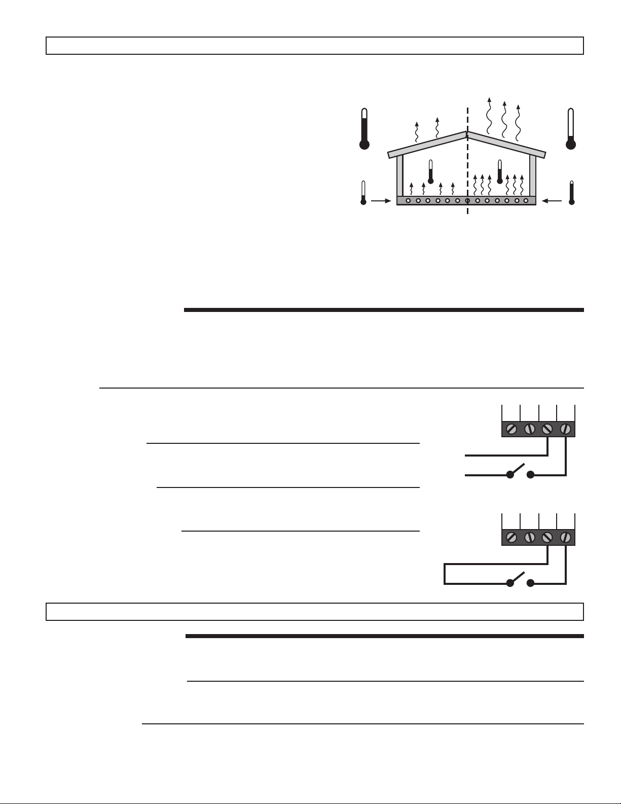
Outdoor Reset Mode of Operation
In order to properly control a hot water heating system, the amount of heat
supplied to the building must equal the amount of heat lost by the building.
The amount of heat delivered into a building depends on the temperature of
the water in the heating unit and the surface area of the heating unit. Heating units with a small surface area, such as baseboard radiators, require a
higher water temperature than heating units with a larger surface area such
as radiant floors.
The amount of heat lost from a building depends on the outdoor temperature. As the outdoor temperature becomes colder, the amount of heat a
building loses increases.
The operation of a hot water heating system can generally be improved by
adjusting the supply water temperature to the system as the outdoor temperature changes. Using this approach, the heat input to the building can be
matched to the heat lost from the building. This method of controlling the
supply water temperature to a heating system greatly improves the comfort
of the system and is known as Outdoor Reset.
When a Taco Outdoor Sensor is connected to the Variable Speed Mixing Control (VSMC), the VSMC provides outdoor reset. When
operating in the outdoor reset mode of operation, the installer must set the Outdoor Design Temperature and the Design Supply Temperature in order to establish the relationship between the outdoor temperature and the supply water temperature. This is known as
setting the Heating Curve.
SEQUENCE OF OPERATION
When the VSMC receives a Demand and it is not in warm weather shut down (WWSD), the VSMC turns on the system pump and
calculates a Mixing Target temperature. The variable speed heat source side pump is then operated to maintain the Mixing Target
temperature at the mixing supply sensor.
The heat source contact operates as described in the Heat Source Operation section. The VSMC also provides heat source protection
as described in the Heat Source Operation section.
DEMAND
The VSMC requires a demand signal before it will begin operation. The VSMC can use
either a powered or an unpowered demand signal. Once a demand signal is received, the
VSMC displays the demand icon in the display and operates as described above.
Powered Demand
The VSMC recognizes a Powered Demand Signal when 24 V (ac) is applied across the
Com and Heat Dem terminals.
Unpowered Demand
The VSMC recognizes an Unpowered Demand signal when a switch is closed between
the Com and Heat Dem terminals (relay type thermostat or end switch on zone control).
SYSTEM PUMP OPERATION
The VSMC has an internal system pump contact. This contact turns on when the VSMC
has a mixing demand and is not in a WWSD. The integrated system pump as well as an
external heat source pump may be controlled by this relay. By providing proper flow in the
heat source loop, the heat source temperature can be accurately controlled based on the
mixing load.
Powered
Demand
C
24 V (ac)
R
Unpowered
Demand
Boil Out
Switch
Boil Out
Switch
Com Heat
Com Heat
Outdoor Reset Settings
HEATING CURVE SETTINGS
In order to establish the heating curve, the VSMC must be given two points to work with. The first point is the Outdoor Reset Starting
Point and the second point is the Design Condition.
Outdoor Reset Starting Point
The Outdoor Reset Starting Point for the VSMC is fixed at 72°F. This means that when the outdoor temperature is 72°F, the VSMC
calculates a required supply water temperature (Mix Target) of 72°F.
Dem
Dem
Design Conditions
The design conditions represent the supply water temperature required to satisfy the heating system on the typical coldest day of
the year. These are the conditions that are used when calculating the size of the heating equipment needed to heat the building.
The Design Conditions are made up of an outdoor temperature (Outdoor Design) and a supply water temperature (Design Supply).
5 of 16
Page 6

Outdoor Design
The Outdoor Design temperature is the average coldest day of the
year for the area in which the building is located.
Outdoor Reset
Design Supply
The Design Supply temperature is the supply water temperature that
is required to heat the building when the outdoor air temperature is
as cold as the Outdoor Design temperature.
Mix Maximum
Mix
Design
Maximum System Supply
Some systems, such as hydronic radiant floor heating, may require the
maximum supply water temperature to be limited in order to protect
WWSD
certain system components from high temperatures. The VSMC has a
Maximum Supply setting that can be used to limit the maximum temperature that the control is allowed to use for a Mixing Target (MIX TRG)
temperature.
Outdoor
Design
Minimum System Supply
Some applications, such as floor warming, may require the minimum
supply water temperature to be limited in order to provide a certain
level of occupant comfort. The VSMC has a Minimum Supply setting
that can be used to limit the minimum temperature that the control is
allowed to use for a Mixing Target (MIX TRG) temperature. This mini-
Starting
Point
70 60 50 40 30 20 10 0 -10 -20
Outdoor Temperature (F)
mum applies as long as the VSMC has a demand and is not in WWSD.
Warm Weather Shut Down (WWSD)
When the outdoor temperature is warmer than the WWSD setting, the VSMC turns off the heat source and the system pump. If a
demand is received while the VSMC is in a WWSD, the VSMC indicates that the demand has been received by displaying the
Demand pointer however, the MIX TRG remains as “- - -”. The VSMC has a freeze protection feature that does not allow the supply
water temperature to drop below 35°F (2°C) as long as there is a mixing demand signal.
150
140
130
120
110
100
90
Supply Temperature (F)
80
70
60
Setpoint and Delta T Mode of Operation
In certain applications, it is desirable to maintain a fixed supply water temperature. This type of application is a setpoint application.
Examples of setpoint applications include heat pump loops, reheat coils and floor warming.
In specialized applications, such as snow melting, it is desirable to limit the rate of temperature increase in the system from the system‘s
starting temperature to its operating setpoint. This is desired in order to prevent thermal shock of the system. This type of application is
a Delta T application.
If the VSMC is to operate as a setpoint control, the Outdoor Design temperature must be set to OFF and the Mixing Target temperature
must be set to the desired temperature.
If the VSMC is to operate as a Delta T control, a mixing return sensor must be installed, the Outdoor Design temperature must be set to
OFF and both the Delta T Max setting and the Mixing Target temperature must be set to the desired temperature.
In both of these applications, the outdoor sensor is not to be installed.
SEQUENCE OF OPERATION
When the VSMC receives a Demand, the system pump is turned on.
If the Delta T Max setting is set to OFF, the variable speed injection pump is operated to maintain the mixing supply sensor at the
Mixing Target temperature set by the installer.
If the Delta T Max setting is not set to off, the variable speed heat source pump is operated to maintain the mixing supply sensor at
either the Mixing Return temperature plus the Delta T Max setting or the Mixing Target temperature set by the installer whichever is
lower. The heat source contact operates as described in the Heat Source Operation section. The VSMC also provides heat source
protection as described in the Heat Source Operation section.
DEMAND
The VSMC requires a demand signal before it will begin operation. The VSMC can use
either a powered or an unpowered demand signal. Once a demand signal is received, the
VSMC displays the demand pointer in the display and operates as described above.
Powered
Demand
Boil Out
Com Heat
Dem
Powered Demand
The VSMC recognizes a Powered Demand Signal when 24 V (ac) is applied across the
Com and Heat Dem terminals.
6 of 16
C
24 V (ac)
R
Switch
Page 7

Unpowered Demand
The VSMC recognizes an Unpowered Demand signal when a switch is closed between
Unpowered
Demand
Boil Out
Com Heat
the Com and Heat Dem terminals (relay type thermostat or end switch on zone control).
SYSTEM PUMP OPERATION
The VSMC has an internal system pump contact. This contact turns on when the VSMC
has a mixing demand. The system pump as well as an external heat source pump may be
controlled by this relay. By providing proper flow in the heat source loop, the heat source
Switch
temperature can be accurately controlled based on the mixing load.
Setpoint and Delta T Settings
Outdoor Design
The Outdoor Design temperature must be set to OFF.
Mixing Target
The Mixing Target temperature is set to the desired operating temperature of the system.
Delta T Max
The Delta T Max temperature is set to the maximum temperature difference that is desired between the system return temperature
and the system supply temperature. In order to adjust this setting, a system return sensor must be connected to the control.
Dem
Setpoint
Mix Supply = Mix Target
Time
150
140
130
120
110
100
90
Supply Temperature (F)
80
70
60
Mix Target
Start
Delta T Maximum
Mix Supply
Mix Return
Maximum Delta T
Time
120
110
100
90
80
70
60
Supply Temperature (F)
50
40
30F
Heat Source Operation
The VSMC operates the heat source in two basic modes of operation. The VSMC can either “Control” the heat source or “Enable” the
heat source. The mode of operation is determined by the Heat Source Sensor location. The heat source sensor location is determined
using the DIP switch on the back of the circuit board. If the DIP switch is set to ON, the heat source sensor is to be located on the heat
source supply. If the DIP switch is set to OFF, the heat source sensor is to be located on the heat source return.
• If the DIP switch is set to On, the VSMC will “Control“ the heat source (sensor on supply).
• If the DIP switch is set to Off, the VSMC will “Enable” the heat source (sensor on return).
• If the Heat Source Sensor has not been installed, the VSMC will “Enable” the heat source.
Variable Speed Mixing Control
1
HEAT SOURCE CONTROL
When the VSMC controls the heat source, the VSMC opens and closes the heat source contact in order to control the temperature of
the heat source supply water temperature. When the VSMC is controlling the heat source temperature, the VSMC will determine the
heat source supply water temperature that is required to satisfy the demands of the system. The VSMC will also determine a differential that is sufficient to minimize short cycling of the heat source. The VSMC will then cycle the heat source using these parameters.
Differential
An on / off heat source must be operated with a differential in order to prevent short cycling. When the supply water temperature
drops 1/2 of the differential below the required heat source supply temperature, the heat source is turned on. The heat source is then
7 of 16
ONOFF
Page 8

kept on until the supply water temperature rises 1/2 of the differential above the required heat source supply temperature. If the
differential is too wide, there can be large supply water temperature swings; however, if the differential is too narrow, the heat source
short cycles and operates inefficiently. This control automatically calculates the heat source differential in order to achieve an
appropriate balance between temperature swings and heat source efficiency. This also permits the control to adapt to changing
loads and conditions. The VSMC only operates the heat source once the output of the injection circulator exceeds 10% of flow.
HEAT SOURCE ENABLE
When the VSMC “Enables” the heat source, the VSMC opens and closes the heat source contact based on the output of the variable
speed pump. The actual temperature and cycling of the heat source is then determined by other controls or the aquastats on the heat
source itself.
When operating in the heat source enable mode, the heat source contact turns on once the variable speed output exceeds 25%. The
heat source contact shuts off if the output of the variable speed drops below 5% for more than three minutes or if the demand is
removed from the VSMC.
HEAT SOURCE PROTECTION (HEAT SOURCE MINIMUM)
Cool water is often returned to the heat source from low temperature radiant floor heating systems or snow melting systems. This cool
heat source return water may cause the heat source to operate at such a low temperature that the flue gases condensate. Alternatively, when the heat source surfaces are hot due to previous loads such as domestic hot water generation, the large temperature
difference (Delta T) between the heat source and its return water can cause the heat source to become thermally shocked. Proper
protection of the heat source under these circumstances is required.
When a heat source sensor is connected to the control, the VSMC is capable of providing heat source protection. When providing heat
source protection, the VSMC limits the output of the variable speed pump in order to reduce the amount of cool water being returned
to the heat source. This allows the heat source temperature to increase to a point that avoids flue gas condensation.
Heat Source Protection with Heat Source Enable
When the Heat Source Sensor is set to the “Return” setting the control begins to back off the variable speed pump when the heat
source temperature drops below the Heat Source Minimum Setting.
Heat Source Protection with Heat Source Control
When the Heat Source Sensor is set to the “Supply” setting the control begins to back off the variable speed pump when the heat
source temperature drops 1/2 of the Differential below the Heat Source Minimum Setting.
Note: If a heat source sensor is not installed, the VSMC cannot provide heat source protection.
Set Up of Variable Speed Mixing Control
CAUTION
Improper installation and operation of this product could result in damage to the equipment and possibly personal injury. It is your
responsibility to ensure that this product is installed in a safe manner according to all of the applicable codes, standards and instructions. The electronic control contained in this product is not intended as a primary limit control. Removal of the PC Board from its
enclosure can result in damage to the control and possibly even personal injury. Refer to qualified personnel for servicing.
STEP ONE - REMOVING THE VARIABLE SPEED MIXING CONTROL FROM THE X – PUMP BLOCK
• Remove the screw from the front of the control.
• Grasp the front of the control and remove it from the green plastic enclosure surrounding the injection mixing block.
• Wiring to the control is connected to the back of the circuit board using either the indicated spade connectors, molex connectors or
the snap on terminal plugs. These may need to be disconnected to fully remove the control.
8 of 16
Page 9

STEP TWO - INSTALLING THE SENSORS
Outdoor Sensor
Note: The temperature sensor is built into the plastic enclosure.
If the X – Pump Block is to be used in the outdoor reset mode, the Outdoor Sensor must be
installed. If the X – Pump Block is to be used in either the setpoint or a delta T mode, the
Outdoor sensor is not required and does not need to be installed. (See pages 5 to 7 for a
complete description of the available modes.)
• Remove the screw from the center of the sensor and pull the front cover off of the sensor.
• The outdoor sensor can either be mounted directly to an outside wall or onto a standard
electrical box. Wiring can enter the sensor either through the bottom or the back of the plastic
enclosure.
• The sensor should be mounted on a wall which best represents the heat load on the building
(i.e. a north facing wall for most buildings and a south facing wall for buildings with a large south
facing glass area). The sensor should not be installed near heat sources such as exhaust
vents or window openings.
• The sensor should be installed at an elevation above the ground that will prevent accidental
damage or tampering and above snow line.
• Ensure that the sensor is installed in a sheltered location out of direct sunlight and rain.
• Connect a two conductor wire to the terminal block in the Outdoor Sensor and run the wires
from the Outdoor Sensor back to the Radiant Mixing Control’s location.
Installing the System and Heat Source Sensors
Note: These sensors are designed to be mounted on a pipe or in a temperature well.
• These sensors can be strapped directly to the pipe using the cable tie provided with the
sensors. Insulation should be installed around the sensors to reduce the effect of air currents
on the temperature measurement. Care should be taken not to over-tighten the cable tie as
this can cause damage to the sensor.
• The System Supply Sensor is to be installed on the System Supply pipe. This sensor is
required at all times.
• If a Heat Source Sensor is used, install the heat source sensor on either the heat source
supply or the heat source return. Ensure that the DIP switch on the back of the circuit
board of the VSMC is set to ON if the sensor is installed on the heat source supply and
set to OFF if the sensor is installed on the heat source return. If heat source control and
heat source protection are not required in the application, the heat source sensor does not
need to be installed.
• If a System Return Sensor is to be used, install the sensor on the system return pipe. This
sensor is only required if the VSMC is operating in the Delta T mode.
STEP THREE - WIRING THE VSMC
• Before wiring the control, ensure that power to all circuits is off.
• Ensure that all wires are stripped to a minimum of 3⁄8" (9 mm) in order to ensure proper connection to the low voltage terminals.
• Provide a separate circuit with a minimum 15 A capacity in order to insure proper operation.
Wiring Power to the VSMC
Using the supplied line cord, connect the white wire with the 1⁄4 inch female
spade connector to the 1⁄4 inch male spade connector labelled “N” on the
back of the VSMC circuit board. Connect the black wire with the 1⁄4 inch
female spade connector to the 1⁄4 inch male spade connector labelled “H” on
the back of the VSMC circuit board. Connect the green wire to the ground
screw located on the casting of the X – Pump Block.
Wiring to the X – Pump Block
Wiring to the Variable Speed Pump
Connect the variable speed pump’s three pin molex connector from the
X – Pump Block to the matching three pin molex connector labelled “Var”
on the back of the VSMC circuit board.
Wiring the X – Pump Block System Pump
Connect the system pump’s four pin molex connector from the X – Pump
Block to the matching four pin molex connector labelled “Sys” on the back
of the VSMC circuit board.
967-01
Use copper
conductors only
Com Sup Sys
Ret
Power: 120 V +/- 10%
R
50/60 Hz, 750 VA
Var. Speed: 120 V
CUS
(ac) 1A
158033
BOILER
Com Boil Out Com Heat
Pmp Relay: 120 V
(ac) 5 A, 1/6 hp
Dem
Injection Mixing
Meets Class B
Canadian ICES
FCC Part 15
Sys
T1A 250V
Pmp
Var
ON
OFF
1
2
3
4
5
Man
H
N
9 of 16
Page 10

Wiring the Sensors
Do not apply power to the sensors or the sensor terminals as this will damage either the sensors or the control.
Begin by removing the eight (8) pin plug-in terminal block from the VSMC’s circuit board. To do
this, pull the terminal block directly away from the circuit board.
Ret
ComCom Sup
System Supply Sensor (Required)
Connect the two wires from the System Supply Sensor directly to the “Com” and “Sup” terminals of the terminal block. The System Supply Sensor is used to measure the supply temperature being delivered to the system.
Ret
ComCom Sup
System Return Sensor (Delta T Limiting Mode)
Connect the two wires from the System Return Sensor directly to the “Com” and “Sys Ret”
terminals of the terminal block. The System Return Sensor is used to measure the return
temperature from the system.
Ret
ComCom Sup
Heat Source Sensor (Optional)
Connect the two wires from the Heat Source Sensor directly to the “Com” and “Boil” terminals
of the terminal block. The Heat Source Sensor is used to measure the heat source temperature.
Boil OutSys
Boil OutSys
Boil OutSys
Com Heat
Dem
Com Heat
Dem
Com Heat
Dem
Outdoor Sensor (Reset Mode)
Connect the two wires from the Outdoor Sensor directly to the “Com” and “Out” terminals of
Ret
Boil OutSys
ComCom Sup
Com Heat
Dem
the terminal block. The outdoor sensor is used to measure the outdoor air temperature.
Wiring the External Heat Source Pump (Optional)
Using a 3⁄16 inch female spade connector, connect the hot side of the heat source pump circuit to the male spade connector labelled
“Pmp” located on the back of the VSMC circuit board. Connect the neutral side of the heat source pump circuit to the neutral (N) side
of the VSMC’s input power supply. When using this option the line cord should be removed and the VSMC hard wired.
Wiring the Heat Demand (Required)
Ret
Boil OutSys
ComCom Sup
Com Heat
Dem
The Heat Demand circuit can be wired using either a powered signal or an unpowered switch
closure.
Powered Heat Demand
Powered Demand
If a powered demand is being used, connect the switched side of the 24 V (ac) demand circuit
to the “Heat Dem” terminal of the terminal block. Connect the second side of the
24 V (ac) demand circuit to the “Com” terminal of the terminal block.
Unpowered Demand
If an unpowered demand is being used, connect one side of the demand switch to the “Heat
Dem” terminal of the terminal block. Connect the second side of the demand switch to the
C
24 V (ac)
R
Unpowered Heat Demand
Ret
Switch
Boil OutSys
ComCom Sup
Com Heat
Dem
“Com” of the terminal block (relay type thermostat or end switch on zone control).
Wiring the Heat Source
Begin by removing the two (2) pin plug-in terminal block from the VSMC’s circuit board. To do
this, pull the terminal block directly away from the circuit board.
Switch
The Heat Source Relay is a switch that is to be used in the heat source circuit. There is no power
available on these terminals from the VSMC. Connect the Heat Source relay in series with the
Boiler
control circuit of the heat source.
STEP FOUR - RECONNECTING THE TERMINAL BLOCKS
Insert the eight (8) pin plug-in terminal block into the eight (8) pin terminal header on the VSMC circuit board. Press firmly until it snaps
into place.
Insert the two (2) pin plug-in terminal block into the two (2) pin terminal header on the VSMC circuit board. Press firmly until it snaps
into place.
STEP FIVE - MOUNTING THE VSMC
• Begin by pushing all excess wiring back into the X – Pump Block.
• Place the VSMC into the X – Pump Block’s plastic enclosure.
• Insert the screw into the hole located on the face of the VSMC and tighten the screw to fasten the VSMC to the X – Pump Block
Enclosure. Do not overtighten.
STEP SIX - POWERING THE VSMC
Apply power to the VSMC circuit by plugging in the line cord.
10 of 16
Page 11

Display Operation
POWER UP
On power up, the control displays all segments for 2 seconds followed by the control version
number.
The control then automatically goes to the operating mode and displays either the outdoor
temperature or the mix supply temperature.
VIEW MENU
To advance to the next available View Item, press and release the ITEM button on the face of the control.
VIEW
ADJUST
TIME
SCHD
OUT
INDR
RET
DIFFMASS
DSGN
TERM
MINMAX
STG
MOTR UNOCC
XCHG
Opn WWSD
%
1
Cls
MIX
BOIL SUP
SETP TARG
ROOM
T
MoTuWeThFrSaSu
F DLY
BST
123
%
DHW 12
2
12
PURG
DHW
MODE
FC
min
hr %
AMPM
DEM
!
Outdoor Temperature
The outdoor temperature is displayed when the OUTDR element is turned on. This is the
current temperature at the outdoor sensor. The outdoor temperature is only displayed if
an outdoor sensor is installed and the Outdoor Design temperature is not turned off.
Mixing Supply Temperature
The mixing supply temperature is displayed when the MIX SUP elements are turned on.
This is the current temperature at the mixing supply sensor.
Mixing Return Temperature
The mixing return temperature is displayed when the MIX RET elements are turned on.
This is the current temperature at the mixing return sensor. The mixing return temperature
is only displayed if the Outdoor Design temperature is turned OFF and a mixing return
sensor is installed.
Mixing Target Temperature
The mixing target temperature is displayed when the MIX TARG elements are turned on.
This is the temperature the VSMC is currently trying to maintain at the supply sensor.
If “- - -” is displayed, the VSMC is either in WWSD or a demand for heat is not present.
OUT
VIEW
VIEW
VIEW
VIEW
F
%
1
%
1
RET
%
1
%
1
DEM
SUP
MIX
F
DEM
MIX
F
DEM
MIX
TARG
F
DEM
Heat Source Temperature
The heat source temperature is displayed when the BOIL element is turned on. This is the
VIEW
BOIL
F
current temperature at the heat source sensor. The heat source temperature is only displayed if a heat source sensor is installed.
%
1
DEM
ADJUST MENU
To switch between the View menu and the Adjust menu, press and release the MENU button on the face of the control. To advance to
the next available Adjust Item, press and release the ITEM button on the face of the control.
ADJUST
Mixing Target Temperature
The Mixing Target Temperature sets the desired supply temperature when operating in
the setpoint mode. This item is only available if the Outdoor Design setting is set to OFF.
11 of 16
MIX
TARG
F
Page 12

Delta T Maximum
The Delta T Maximum sets the maximum temperature difference between the mixing
return sensor and the mixing supply sensor. This item is only available if Outdoor Design
setting is set to OFF. If a mixing return sensor is not installed, set this item to OFF.
ADJUST
MAX
T
F
Outdoor Design Temperature
The Outdoor Design Temperature is the outdoor temperature used in the heat loss calculation. If the VSMC is used in the outdoor reset mode, this item is set to the typical coldest
outdoor temperature. If the VSMC is used in the setpoint mode, this item is set to OFF.
Mixing Design Temperature
The mixing design temperature is the supply temperature used in the heat loss calculation. This is the supply temperature that is required to heat the building when the outdoor
temperature is as cold as the outdoor design temperature. This item is only available if the
Outdoor Design setting is not set to OFF.
Mixing Maximum Temperature
The mixing maximum temperature is the highest temperature that the control is allowed to
use as a mixing target temperature. This item is only available if the outdoor design setting is not set to OFF.
Mixing Minimum Temperature
The mixing minimum temperature is the lowest temperature that the control is allowed to
use as a mixing target temperature. This item is only available if the outdoor design setting is not set to OFF.
OUT
ADJUST
DSGN
ADJUST
DSGN
ADJUST
ADJUST
MIN
F
MIX
F
MIX
F
MAX
MIX
Heat Source Minimum Temperature
The heat source minimum temperature item should be set to the lowest water temperature at which the heat source can operate without causing the heat source flue gases to
condense. Consult the heat source manufacturer for recommended minimum heat source
supply temperatures. This item is only available if a heat source sensor is connected to
the control.
Warm Weather Shut Down (WWSD)
The warm weather shut down is the outdoor temperature at which the system is shut
down. This item is only available if the outdoor design temperature is not set to OFF.
Units
The units of temperature in which all of the View and Adjust items are viewed in.
The control automatically goes back to the view menu when the buttons are left alone for 20 seconds
All settings will be saved even during power down of the control
ADJUST
MIN
ADJUST
ADJUST
BOIL
F
F
WWSD
F
12 of 16
Page 13

Trouble Shooting
As in any troubleshooting procedure, it is important to isolate the problem as much as possible. By using the Error Messages located on
page 14, the trouble shooting process can be greatly simplified. When an error message is displayed on the VSMC, refer to the error
messages on page 14 to identify the cause of the error and use standard testing procedures to confirm the fault. If you suspect an
external wiring fault, return to step three and carefully check all external wiring connections.
Once the fault has been corrected, press any button on the face of the control to clear the error message.
TEST ROUTINE
The main control functions of the VSMC can be tested by pressing and holding the UP button for more than three (3) seconds.
Continue to hold the UP button and the VSMC will test the outputs in the following sequence.
Step One
The variable speed output is increased from 0% to 100% over 10 seconds.
Step Two
The variable speed output is decreased from 100% to 0% over 10 seconds.
Step Three
The System Pump is turned on for 10 seconds.
Step Four
The Boiler Contact is turned on. After 10 seconds, the Boiler Contact and the
System Pump contact are turned off. The VSMC continues normal operation.
MANUAL OVERRIDE
In the event that the VSMC fails to operate, a manual operation switch is located
on the VSMC’s circuit board. When the manual operation switch is set to Man, the
variable speed pump and the system pump outputs are turned on. This operation
continues until the manual switch is returned to its original position.
967-01
CUS
BOILER
158033
Injection Mixing
Power: 120 V +/- 10%
R
50/60 Hz, 750 VA
Var. Speed: 120 V
(ac) 1A
Pmp Relay: 120 V
(ac) 5 A, 1/6 hp
Meets Class B
Canadian ICES
FCC Part 15
T1A 250V
ON
OFF
1
2
3
4
5
FUSE REPLACEMENT
The Variable Speed output of the VSMC is fuse protected. This fuse is located on
the circuit board on the back of the VSMC. This is a field replaceable item.
Fuse rating: 1 A 1⁄12 hp, fuse T1 A 250 V
Use copper
conductors only
Com Sup Sys
Ret
ADJUSTMENT OF SETTINGS
If the outdoor temperature is cold and the rooms are cold, increase the MIX DSGN
setting by 5°F (3°C) per day.
TESTING THE SENSORS
Do not apply voltage to the sensor or to the sensor input of the control as this will result in damage
to either the sensor, the control, or both the sensor and the control.
A quality testing meter capable of measuring up to 2,000,000 ohms and a good quality digital
thermometer are required to test the sensors. If a digital thermometer is not available, place a
second sensor next to the original sensor and compare the readings.
Begin by measuring the temperature at the sensor location using the digital thermometer. Next,
measure the resistance of the sensor using the testing meter. Ensure that the sensor is disconnected from the control at the time of testing. Using the reference chart below, determine the
sensor’s temperature. Compare the sensor’s temperature to that measured by the digital thermometer. The two temperature readings should be close.
If the sensors temperature is too high, this can indicate that there is a partial short in the sensor
wiring. If the sensor’s temperature is too low, this can indicate that there is a loose connection or
break in the sensor wiring. Isolate and repair the problem. If the problem is isolated to the sensor,
replace the sensor.
Com Boil Out Com Heat
Dem
OHM
Sys
Var
Pmp
Man
H
N
Temperature Resistance
F
-30
-20
-10
0
10
20
C
-34
-29
-23
-18
-12
-7
Ohms
234,000
165,000
118,000
85,500
62,500
46,000
Temperature Resistance
F
30
40
50
60
70
80
C
-1
4
10
16
21
27
Ohms
34,500
26,000
20,000
15,500
12,000
9,300
13 of 16
Temperature Resistance
F
90
100
110
120
130
140
C
32
38
43
49
54
60
Ohms
7,300
5,800
4,700
3,800
3,100
2,500
Temperature Resistance
F
150
160
170
180
190
200
C
66
71
77
82
88
93
Ohms
2,000
1,700
1,400
1,200
1,000
800
Page 14

Error Messages
EEPROM Read Error
The control was unable to read the installers settings from its memory. The
control was forced to load the factory
defaults for all settings. The control will
stop operation until all of the settings in
the Adjust menu have been checked.
Outdoor Sensor Short Circuit
A short circuit has been detected in the
outdoor sensor. The control assumes
an outdoor temperature of 32°F (0°C)
and continues operation. To clear this
error message, correct the short circuit
and press any button on the control.
Outdoor Sensor Open Circuit
An open circuit has been detected in the
outdoor sensor. The control assumes an
outdoor temperature of 32°F (0°C) and
continues operation. To clear this error
message, correct the open circuit and
press any button on the control.
Mixing Supply Sensor Short Circuit
A short circuit has been detected in the
mixing supply sensor. The control continues to operate the injection pump at
a low speed (17 - 18%) as long as a
demand is present. To clear this error
message, correct the short circuit and
press any button on the control.
Mixing Supply Sensor Open Circuit
An open circuit has been detected in
the mixing supply sensor. The control
continues to operate the injection pump
at a low speed (17 - 18%) as long as a
demand is present. To clear this error
message, correct the open circuit and
press any button on the control.
VIEW
VIEW
OUT
VIEW
OUT
VIEW
VIEW
Mixing Return Sensor Short Circuit
A short circuit has been detected in the
mixing return sensor. If the Maximum
VIEW
MIX
RET
Delta T setting is set to OFF, the control continues operation. If the Maximum Delta T setting is not set to OFF,
!
!
the control stops operation until the
fault is corrected. To clear this error
message, correct the short circuit and
press any button on the control.
Mixing Return Sensor Open Circuit
An open circuit has been detected in
the mixing return sensor. If the Maximum Delta T setting is set to OFF, the
!
control continues operation. If the Maximum Delta T setting is not set to OFF,
VIEW
MIX
RET
!
the control stops operation until the
fault is corrected. To clear this error
message, correct the open circuit and
press any button on the control.
Heat Source Sensor Short Circuit
A short circuit has been detected in the
!
heat source sensor. The boiler contact
VIEW
BOIL
is operated as if a heat source sensor
is not installed. The control provides a
heat source enable and does not pro-
SUP
MIX
vide heat source protection. To clear this
!
error message, correct the short circuit
and press any button on the control.
!
Heat Source Sensor Open Circuit
An open circuit has been detected in the
VIEW
BOIL
heat source sensor. The boiler contact
is operated as if a heat source sensor is
not installed. The control provides a heat
MIX
SUP
source enable and does not provide heat
!
source protection. To clear this error
message, correct the open circuit and
press any button on the control. If the
sensor was deliberately removed, power
!
down the control.
Replacing Cartridge Assembly
1. Disconnect the electrical supply.
2. Reduce system pressure to 0 psi and allow system to return to room temperature. Isolate the XPB by closing the service valves or
draining the system.
3. Remove screw holding the VSMC module to X – Pump Block. Unplug both pump Molex plugs, power cord and heat source & sensor
terminal blocks from VSMC. Set VSMC control aside in safe place, away from water damage.
4. Remove 4 screws holding plastic housing to pump castings.
5. Remove the body bolts and swing motor assembly away from the body.
6. Pull cartridge out of the motor housing.
7. Install replacement cartridge, making sure that the cover plate is between the cartridge flange and motor.
8. Make sure the replacement cartridge corresponds to the full circulator product number. A complete parts list is available from your
local plumbing supply wholesaler.
9. Reassemble the circulator using the new gasket and bolts supplied.
10. Reassemble plastic housing and VSMC control in reverse order.
11. Follow the “Installation” procedure to start up the circulator.
14 of 16
Page 15

Technical Data
PERFORMANCE DATA
Flow Range ................................................... 0 - 7.5 GPM
Head Range .................................................. 0 - 15.5 Feet
Minimum Fluid Temperature .......................... 32°F (0°C)
Maximum Fluid Temperature ......................... 180°F (85°C)
Maximum Working Pressure ......................... 125 psi
Connections .................................................. 3/4" NPT
C US UL Mark
FOR INDOOR USE ONLY
MATERIALS OF CONSTRUCTION
Casing (body) ................................................ Bronze
Stator Housing .............................................. Steel
Cartridge ....................................................... Stainless Steel
Impeller ......................................................... Non-Metallic
Shaft .............................................................. Ceramic
O-Ring & Gaskets ......................................... EPDM
Standard Heat Exchanger ............................. Stainless Steel
Single Wall Design
Optional Heat Exchanger .............................. Stainless Steel
Double Wall Design
DIMENSIONS & WEIGHT
Model: XPB-1 Ship Weight: 26.5 lbs (12.0 kg)
ELECTRICAL DATA CHART
Volts ....................................................... 120
Hz ........................................................... 60
Ph ........................................................... 1
Amps ...................................................... 2
RPM ....................................................... 3250
HP .......................................................... 2 @ 1/25
Motor Type ............................................. Permanent Split
Capacitor Impedance
Protected
CONTROL ADJUSTMENT MENU
Mixing Setpoint Temperature ........................ 60° to 185° F
Maximum Temperature Difference
Between Mixing Supply and Return .............. 10° to 70° F, Off
Design Outdoor Air Temperature ................... -60° to 32° F, Off
Design Heating System Supply Water
Temperature .................................................. 70° to 185° F
Maximum Mixing Target Supply .................... 80° to 185° F
Minimum Mixing Target Supply
Fluid Temperature ......................................... 35° to 150° F, Off
Minimum Heat Source Target Supply
Water Temperature ....................................... 80° to 180° F, Off
5
⁄8"
9
5
3
⁄8"
1
8
⁄4"
8"
1
⁄8"
4
18
5"
31⁄2"
3
16
⁄8"
3
⁄8"
12
3
⁄8"
1
⁄8"
4
1
⁄8"
4
3
⁄4"
6
CAUTION:
1. The addition of petroleum based fluids or certain chemical additives to systems utilizing TACO equipment voids the
warranty.
2. Use supply wires suitable for 90°C – ATTENTION: Employer des fils d´alimentation adequats pour 90°C.
WARNING:
1. To avoid electrical shock, disconnect the power supply to the circulator and the main electrical unit.
2. Do not use in swimming pool or spa areas; pump has not been investigated for this application
3
2
⁄4"
1
2
⁄2"
1
15
⁄8"
5
⁄8"
15 of 16
Page 16

Cleaning
The exterior of the control can be cleaned using a damp cloth. Do not use any solvents. Moisten the cloth and wring out any excess
water before cleaning the control.
Technical Data
VSMC - Variable Speed Mixing Control
Control - Microprocessor PID control: This is not a safety (limit)
control
Ambient Conditions - Indoor use only, 32 to 185°F (0 to 85°C), <90% RH non-
condensing
Power Supply - 120 V (ac) +/- 10% 50/60 Hz 720 VA
Var. Pump - 120 V (ac) 1 A 1/12 hp, fuse T1 A 250 V
Sys / Pmp Relay - 120 V (ac) 5 A 1/4 hp, pilot duty 240 VA
Boiler Relay - 120 V (ac) 5 A 1/4 hp, pilot duty 240 VA
Demand - 24 V (ac) 0.1 VA or Dry contact
Sensors - NTC thermistor, 10 kohm @ 77°F (25°C +/- 0.2°C) B=3892
Included - Taco Outdoor Sensor and 2 Taco Strap-on Sensors
PATENT PENDING
VIEW
%
1
ITEM
MENU
X - PUMP BLOCK
MIX SUP
F
DEM
TM
XPB-1
U
L
R
US
C
The installer must ensure that this control and its wiring are isolated and/or shielded from strong sources of electromagnetic noise.
Conversely, this Class B digital apparatus complies with Part 15 of the FCC Rules and meets all requirements of the Canadian Interference-Causing Equipment Regulations. However, if this control does cause harmful interference to radio or television reception, which
can be determined by turning the control off and on, the user is encouraged to try to correct the interference by reorienting or relocating
the receiving antenna, relocating the receiver with respect to this control, and/or connecting the control to a different circuit from that to
which the receiver is connected.
Limited Warranty Statement
Taco, Inc. will repair or replace without charge (at the
company’s option) any product or part which is proven
defective under normal use within one (1) year from the
date of startup or one (1) year and six (6) months from the
date of shipment (whichever occurs first). Taco, Inc. will
repair or replace without charge (at the company’s option)
any Taco “00” Series circulator cartridge that is proven
defective under normal use within three (3) years from the
date of manufacture.
In order to obtain service under this warranty, it is the
responsibility of the purchaser to promptly notify the local
Taco stocking distributor or Taco in writing and promptly
deliver the subject product or part, delivery prepaid, to the
stocking distributor. For assistance on warranty returns, the
purchaser may either contact the local Taco stocking
distributor or Taco. If the subject product or part contains no
defect as covered in this warranty, the purchaser will be
billed for parts and labor charges in effect at time of factory
examination and repair.
Any Taco product or part not installed or operated in
conformity with Taco instructions or which has been subject
to misuse, misapplication, the addition of petroleum-based
fluids or certain chemical additives to the systems, or other
abuse, will not be covered by this warranty.
If in doubt as to whether a particular substance is suitable
for use with a Taco product or part, or for any application
restrictions, consult the applicable Taco instruction sheets
or contact Taco at (401-942-8000).
Taco reserves the right to provide replacement products and
parts which are substantially similar in design and
functionally equivalent to the defective product or part. Taco
reserves the right to make changes in details of design,
construction, or arrangement of materials of its products
without notification.
TACO OFFERS THIS WARRANTY IN LIEU OF ALL
OTHER EXPRESS WARRANTIES. ANY WARRANTY
IMPLIED BY LAW INCLUDING WARRANTIES OF
MERCHANTABILITY OR FITNESS IS IN EFFECT ONLY
FOR THE DURATION OF THE EXPRESS WARRANTY
SET FORTH IN THE FIRST PARAGRAPH ABOVE.
THE ABOVE WARRANTIES ARE IN LIEU OF ALL OTHER
WARRANTIES, EXPRESS OR STATUTORY, OR ANY
OTHER WARRANTY OBLIGATION ON THE PART OF
TACO.
TACO WILL NOT BE LIABLE FOR ANY SPECIAL,
INCIDENTAL, INDIRECT OR CONSEQUENTIAL
DAMAGES RESULTING FROM THE USE OF ITS
PRODUCTS OR ANY INCIDENTAL COSTS OF
REMOVING OR REPLACING DEFECTIVE PRODUCTS.
This warranty gives the purchaser specific rights, and the
purchaser may have other rights which vary from state to
state. Some states do not allow limitations on how long an
implied warranty lasts or on the exclusion of incidental or
consequential damages, so these limitations or exclusions
may not apply to you.
16 of 16
 Loading...