

Page 1
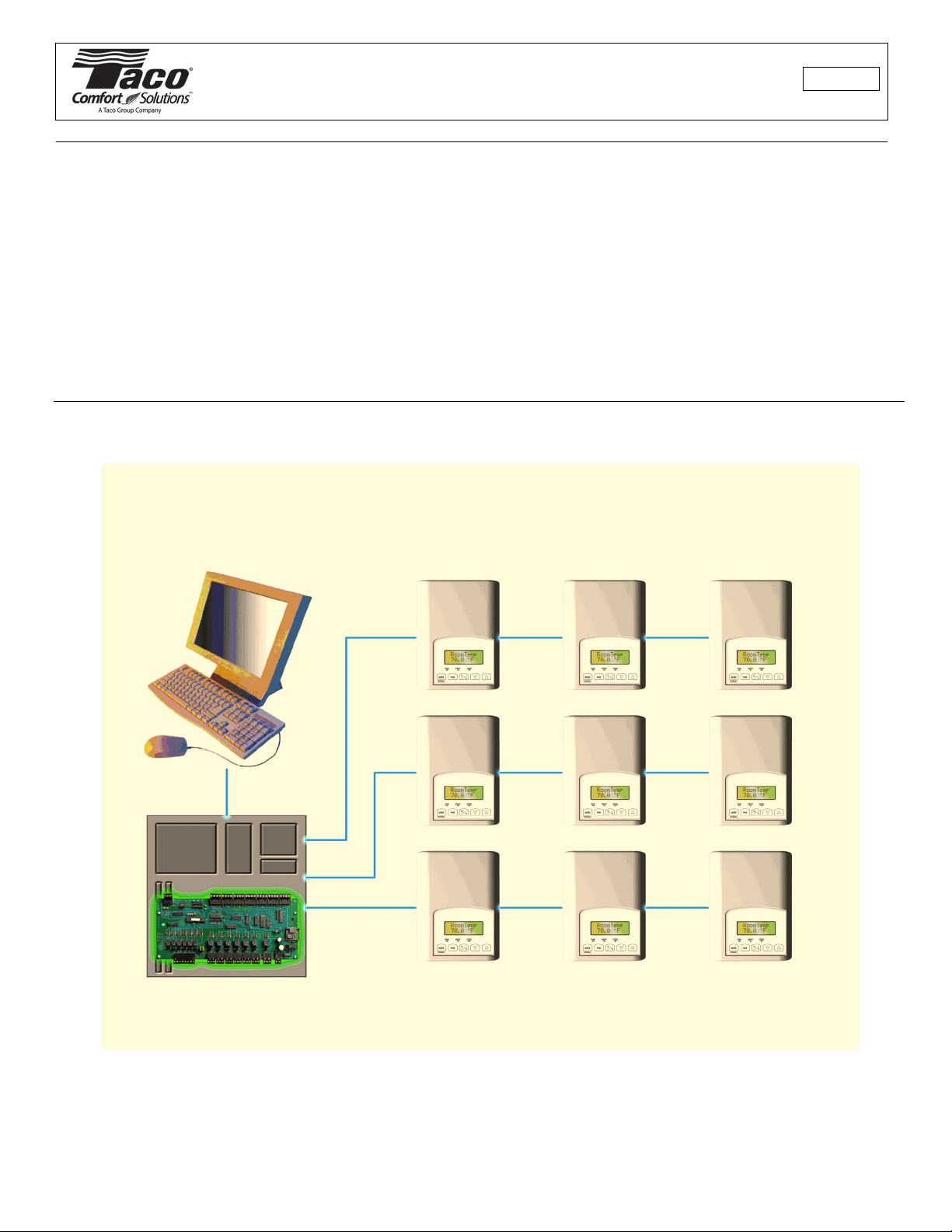
Integration Manual
VT7300 Series Thermostats
102-221
SUPERSEDES: New EFFECTIVE: November 1, 2008
LonWorks Integration Manual
PIR Ready VT7300 Series
24 Vac Low Voltage Fan Coil Thermostats
For Commercial and Lodging HVAC Applications
Page 2

Product Overview
The VT7300 PI thermostat family is specifically designed for fan coil control. The
product features a backlit LCD display with dedicated function menu buttons for simple
operation. Accurate temperature control is achieved due to the product’s PI
proportional control algorithm, which virtually eliminates temperature offset associated
with traditional, differential-based thermostats.
Models are available for On/Off, 3 point floating and analog 0 to 10 Vdc control.
All models contain can control three, two or single fan speed. 3 additional inputs are
also provided for monitoring and / or various advanced functions.
All models feature configurable System and Fan button functions to meet all possible
applications. They all contain an SPST auxiliary switch that can be used to control
lighting or auxiliary reheat.
The thermostats are also compatible with the new TACO PIR cover accessories. Thermostats equipped with a PIR cover
provide advanced active occupancy logic, which will automatically switch occupancy levels from Occupied to Stand-By
and Unoccupied as required by local activity being present or not. This advanced occupancy functionality provides
advantageous energy savings during occupied hours without sacrificing occupant comfort. All thermostats can be ordered
with or without a factory installed PIR cover (see notes below ).
The additional following documents are available at: www.taco-hvac.com
• PIR application information and examples, are available on document: PIR Application Guide 102-354
• PIR cover installation information is available on document: PIR Cover Install Guide 102-355
• Detailed information on the thermostat (VT73xxX5x21x), is available on document:102-220
Contents
• Thermostat Objects
• SNVTs and SCPTs Table Per Model
• Input Network Variables (nvi’s) Description
• Output Network Variables (nvo’s) Description
• Configuration Properties (nci’s) Description
• Integration - Global Commands
• Integration - Graphic User Interface (GUI) Objects
• Integration - Configuration Objects
• Wiring Guide
Overview
Network Configuration
Maximum Number Of Devices
Maximum Cable Length
EI-485 Repeaters
Terminators
• Network Adapter
• Software Files
• RoHS and Non-RoSH APB and NXE Files
• Device Identification
• Tips And Things You Need To Know
• Troubleshooting Section
• Document Control
2
Page 3
Thermostat Objects
VT7300 Space Comfort Controller
Object Type #8500
nviSpaceTemp
SNVT_temp_p
nviOutdoorTemp
SNVT_temp_p
nviSetpoint
SNVT_temp_p
nviSpaceRH
SNVT_lev_percent
nviFanSpeedCmd
SNVT_switch
nviAuxHeatEnable
SNVT_switch
nviOccManCmd
SNVT_occupancy
nviApplicMode
SNVT_hvac_mode
nviHeatCool
SNVT_hvac_mode
Mandatory
Network
Variables
Optional
Network
Variables
nvoSpaceTemp
SNVT_temp_p
nvoUnitStatus
SNVT_hvac_status
nvoDischAirTemp
SNVT_temp_p
nvoSpaceRH
SNVT_lev_percent
nvoEffectOccup
SNVT_occupancy
nvoTerminalLoad
SNVT_lev_percent
nviRemLockout
SNVT_count
nviDhumidLCK
SNVT_switch
nviAuxOut
SNVT_switch
Configuration Properties
Send Heartbeat (mandatory)
Temperature Setpoints (mandatory)
Minimum Send Time (optional)
Receive Heartbeat (optional)
Manufacturer
Network
Variables
Manufacturer Configuration Properties
Please see the manual for details.
Plug-In for configuration provided.
nvoSCCstatus
SNVT_state_64
3
Page 4
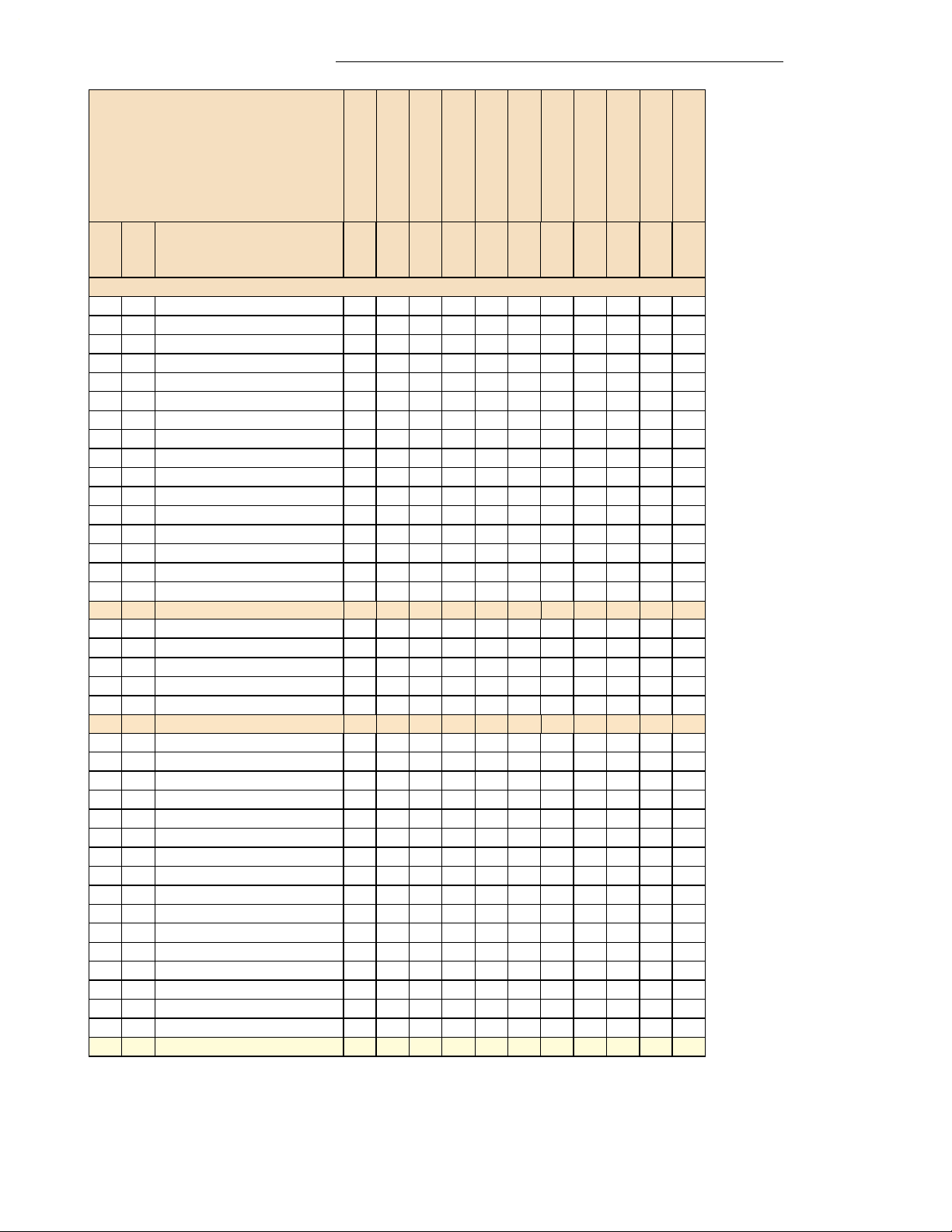
SNVTs
1
and SCPTs2 Table Per Model
Model Number
VT7300F5x21E
VT7300A5x21E
VT7300C5x21E
VT7350C5x21E
VT7305A5x21E
VT7305C5x21E
VT7355C5x21E
Point Name
No
Sub
N/A: Not applicable on this model
0 nviSpaceTemp XXXXXXXXXXX
1 nviOutdoorTemp XXXXXXXXXXX
2 nviSetpoint XXXXXXXXXXX
3 nviSpaceRH N/A N/A X N/A N/A X N/A X N/A X N/A
4 nviFanSpeedCmd XXXXXXXXXXX
5 nviAuxHeatEnable XXXXXXXXXXX
6 nviOccManCmd XXXXXXXXXXX
7 nviApplicMode XXXXXXXXXXX
8 nviHeatCool XXXXXXXXXXX
9 nviRemLockout XXXXXXXXXXX
10 nviDhumiLCK N/A N/A X N/A N/A X N/A X N/A X N/A
11 nviAuxOut XXXXXXXXXXX
12 nvoSpaceTemp XXXXXXXXXXX
13 nvoDischAirTemp XXXXXXXXXXX
14 nvoSpaceRH N/A N/A X N/A N/A X N/A X N/A X N/A
15 nvoEffectOccup XXXXXXXXXXX
16 nvoUnitStatus X X X X X X X X X X X
1 mode xxxxxxxxxxx
2 heat_output_primary x x xxxxxxxxx
4 cool_output x x xxxxxxxxx
6 fan_output x x xxxxxxxxx
7 in_alarm x x xxxxxxxxx
17 nvoSccStatus X X X X X X X X X X X
1 StateTerminal BO2 x x xxxxN/AN/AN/AN/AN/A
2 StateTerminal BO1 N/A x x N/A x x N/A N/A N/A N/A N/A
3 StateTerminal BO4 N/A x x N/A x x N/A N/A N/A N/A N/A
4 StateTerminal BO3 x x xxxxN/AN/AN/AN/AN/A
5 StateTerminal BO5 x x xxxxxxxxx
6 FanLow x x xxxxxxxxN/A
7 FanMed xxxxxxxxxxN/A
8 FanHigh x x xxxxxxxxx
9 UI 3 Status xxxxxxxxxxx
10 BI 2 Status xxxxxxxxxxx
11 BI1 Status xxxxxxxxxxx
12 Local PIR Motion xxxxxxxxxxx
13 Service Alarm xxxxxxxxxxx
14 Filter Alarm xxxxxxxxxxx
15 Window Opened x x xxxxxxxxx
16 Dehumidification Active N/A N/A x N/A N/A x N/A x N/A x N/A
18 nvoTerminalLoad X X X X X X X X X X X
1: SNVTs: Standard Network Variables Types
2: SCPTs: Standard Configuration Parameters Types
VT7350F5x21E
VT7305F5x21E
VT7355F5x21E
VT7300M5x21E
4
Page 5

Model Number
VT7300F5x21E
VT7350F5x21E
VT7305F5x21E
VT7300C5x21E
VT7300A5x21E
VT7305A5x21E
VT7350C5x21E
VT7305C5x21E
VT7355C5x21E
Point Name
No
Sub
N/A: Not applicable on this model
19 nciSetpoints X X X X X X X X X X X
1 occupied_cool xxxxxxxxxxx
2 standby_cool xxxxxxxxxxx
3 unoccupied_cool xxxxxxxxxxx
4 occupied_heat xxxxxxxxxxx
5 standby_heat xxxxxxxxxxx
6 unoccupied_heat xxxxxxxxxxx
20 nciRHmodel N/A N/A X N/A N/A X N/A X N/A X N/A
1 RHdisplay N/A N/A x N/A N/A x N/A x N/A x N/A
2 RHsetpoint N/A N/A x N/A N/A x N/A x N/A x N/A
3 DehumHyst N/A N/A x N/A N/A x N/A x N/A x N/A
4 DehumCool N/A N/A x N/A N/A x N/A x N/A x N/A
5 RHcalib N/A N/A x N/A N/A x N/A x N/A x N/A
21 nciGenOpt X X X X X X X X X X X
1 Control Type N/A x x N/A x x N/A N/A N/A N/A N/A
2 Drive Time xxxxxxN/AN/AN/AN/AN/A
3 Cycles Per Hour x x xxxxN/AN/AN/AN/AN/A
4 Reverse Acting Output N/A N/A N/A N/A N/A N/A x x x x x
5 BI1 xxxxxxxxxxx
6 BI2 xxxxxxxxxxx
7 UI3 xxxxxxxxxxx
8 Menu Scroll x x xxxxxxxxx
9 Auto Mode xxxxxxxxxxN/A
10 Temperature Scale xxxxxxxxxxx
11 Pipes # Main out config x x xxxxxxxxx
12 Sequence of Operation x x xxxxxxxxN/A
13 Fan Menu Sequence x x xxxxxxxxN/A
14 Heat Maximum setpoint x x xxxxxxxxx
15 Cool Minimum setpoint x x xxxxxxxxx
16 SetpointType x x xxxxxxxxx
17 Temporary Occ Time xxxxxxxxxxx
18 Deadband x x xxxxxxxxx
19 Calibration Room Sensor x x xxxxxxxxx
20 Auxiliary Contact Config x x xxxxxxxxx
21 Reheat Time Base x x xxxxxxxxx
22 Fan Mode xxxxxxxxxxx
23 PIR Stand-By Timer x x xxxxxxxxx
24 PIR Unoccupied Timer x x xxxxxxxxx
22 nciSccModel X X X X X X X X X X X
1 Thermostat Model x x xxxxxxxxx
2 Software Version xxxxxxxxxxx
23 nciHvacType XXXXXXXXXXX
24 nciSndHrtBt XXXXXXXXXXX
25 nciMinOuttM XXXXXXXXXXX
26 nciRcvHrtBt XXXXXXXXXXX
27 nciMajVer XXXXXXXXXXX
28 nciMinVer XXXXXXXXXXX
VT7355F5x21E
VT7300M5x21E
5
Page 6

Input Network Variables (nvi’s) Description
Parameter Variable Name Function
Room
Temperature
network input
SNVT_temp_p
nviSpaceTemp
This input network variable provides a network remote temperature
value to the thermostat. When linked of written to, the internal
temperature reading (internal sensor) is no longer used.
Valid Range: 40 to 122°F (-40 to 50°C)
Default Null (release) Value: 621.81°F (327.67°C or 0x7FFF)
This network variable is subject to the Receive HeartBeat Time,
nviRcvHrtBt.
Outdoor Air
Temperature
network input
SNVT_temp_p
nviOutdoorTemp
This input network variable provides outdoor air temperature
information to the thermostat from a network value temperature
value. The device will automatically display the value on its display
when linked.
Valid Range: 40 to 122°F (-40 to 50°C)
Default Null (release) Value: 621.81°F (327.67°C or 0x7FFF)
Occupied
Cool & Heat
Setpoints
network Input
SNVT_temp_p
nviSetpoint
This input network variable is used to allow the occupied
temperature setpoints only to be changed via the network from a
single analog value. (Note: the Stand-By and Unoccupied setpoints
are not changed). The corresponding heating and cooling values
are derived from the minimum deadband configuration value
Default Null Value: 621.81°F (327.67°C or 0x7FFF)
Ex. If the minimum deadband configuration value = 2 °F and
nviSetpoint = 70°F.
• The resulting Occupied heating setpoint will equal 69 °F which is
derived from 70 °F minus _ the minimum deadband configuration
value of 2 °F
• The resulting Occupied cooling setpoint will equal 71 °F which is
derived from 70 °F plus _ the minimum deadband configuration
value of 2 °F
Room
Humidity
network input
SNVT_lev_percent
nviSpaceRH
This input network variable is the measured room humidity in
percent monitored by the thermostat.
Valid Range: 5 to 90%
Default Null Value: +163.835 (0x7FFF)
This network variable is subject to the Receive HeartBeat Time,
nviRcvHrtBt
6
Page 7

Parameter Variable Name Function
Fan Mode network input
SNVT_switch
nviFanSpeedCmd
This input network variable is used to connect an external fan
speed switch to the node or to allow any supervisory device to
override the fan speed controlled by the node’s control algorithm.
This input is used in conjunction with FanMenu bit in nciGenOpts.
Default Null Value: AUTO (state = 0xFF)
Valid Range:
Fan
Menu
Value
State Value Equivalent
Percent
Requested Speed
Sequence of
Operation
network input
SNVT_switch
nviAuxHeatEnable
0
0
1
1
1
1
1
N/A N/A Off - Not Used
0 0% Off - Not Used
1 to 66 0.5 to 33% Low
67 to 133 33.5 to 66.5% Medium
134 to 200 67 to 100% High
201 to 255 100% 3 – Not Used
0xFF N/A N/A Auto – Not Used
1
0 n/ N/A Off – Not Used
1 0 0% Off – Not Used
1 0 to 100 0.5 to 50% Low
1 101 to 200 50.5 to 100% High
1 201 to 255 100% 2 – Not Used
0xFF N/A N/A Auto – Not Used
2
0 N/A N/A Off - Not Used
1 0 0% Off - Not Used
1 1 to 66 0.5 to 33% Low
1 67 to 133 33.5 to 66.5% Medium
1 134 to 200 67 to 100% High
1 201 to 255 100% 3 – Not Used
0xFF N/A N/A Auto
3
0 n/ N/A Off – Not Used
1 0 0% Off – Not Used
1 0 to 100 0.5 to 50% Low
1 101 to 200 50.5 to 100% High
1 201 to 255 100% 2 – Not Used
0xFF N/A N/A Auto
4
0 n/ N/A Off – Not Used
1 0 0% Off – Not Used
1 1 to 200 0.5 to 100% On (High)
1 201 to 255 100% On – Not Used
0xFF N/A N/A Auto
This input network variable is used to enable or disable the
1
auxiliary heat stage.
This input is used in conjunction with nviHeatCool and SeqOper.
Default Null Value: AUTO (state = 0xFF)
Set value to 100% for both On & Off state
Valid Range:
See note 1 below
State Value Auxiliary Heat Operation
0 N/A Disabled – Not Used
1 0 % Disabled
1 1 to 99% Partially Enabled – Not Used
1 100% Enabled
0xFF N/A Enabled (invalid)
7
Page 8

Parameter Variable Name Function
Occupancy network input
SNVT_occupancy
nviOccManCmd
This input network variable is used to command the Space
Comfort Controller into different occupancy modes. It is typically
set by a supervisory node to remotely control the occupancy
modes to override the local occupancy routines of the thermostat.
Default Null Value: OC_NUL = 0xFF
Valid Range:
System Mode network input
SNVT_hvac_mode
nviApplicMode
This network variable input is used to coordinate the Space
Comfort Controller with any node that may need to control the
heat/cool changeover of the unit.
This input is used in conjunction with nviHeatCool and SeqOper.
Default Null Value: HVAC_AUTO.
This network variable is subject to the receive heartbeat time,
nciRcvHrtBt
Valid Range:
0 = OC_OCCUPIED *
1 = OC_UNOCCUPIED )
2 = OC_BYPASS – Not Used
3 = OC_STANDY – Not Used
0xFF = OC_NUL (Release to internal occupancy)**
* OC_OCCUPIED and OC_UNOCCUPIED commands will
always have full authority over the local occupancy routines
of the thermostat may they be a local input or a PIR cover.
** OC_NUL command will release the thermostat to use its
own internal occupancy routine driven from one of the digital
input or a PIR cover installed on board.
0 = HVAC_AUTO
1 = HVAC_HEAT
2 = HVAC_MRNG_WRMUP – Not Used
3 = HVAC_COOL
4 = HVAC_NIGHT_PURGE – Not Used
5 = HVAC_PRE_COOL – Not Used
6 = HVAC_OFF
7 = HVAC_TEST – Not Used
8 = HVAC_EMERG_HEAT – Not Used
9 = HVAC_FAN_ONLY – Not Used
12 = HVAC_MAX_HEAT – Not Used
13 = HVAC_ECONOMY – Not Used
14 = HVAC_DEHUMID – Not Used)
15 = HVAC_CALIBRATE – Not Used)
0xFF = HVAC_NUL – Not Used
8
Page 9

Parameter Variable Name Function
Sequence of
operation
network input
SNVT_hvac_mode
nviHeatCool
1
This network variable input is used to coordinate the Space
Comfort Controller with any node that may need to control the
heat/cool changeover of the unit. This input is overridden by
nviApplicMode, unless nviApplicMode is HVAC_AUTO. If
nviApplicMode is HVAC_AUTO, then nviHeatCool determines the
effective mode of the unit.
Default Null Value: HVAC_AUTO.
This network variable is subject to the receive heartbeat time,
nciRcvHrtBt
Valid Range:
See note 1 below
Lockout network input
UNVT_nvi/nvo
nviRemLockout
This network variable input is used to enable or disable user
access to thermostat
Default Null Value: Level 0.
Valid Range:
Level Occupied
0 Yes access Yes access Yes access Yes access
1 Yes access Yes access Yes access No access
2 Yes access No access No access Yes access
3 Yes access No access No access No access
4 No access No access No access Yes access
5 No access No access No access No access
DhumiLCK network input
UNVT_nvi/nvo
nviDhumiLCK
This network variable input is used to enable or disable
dehumidification
Default Null Value: Dehumidification not allowed
Set value to 100% for both On & Off state
Valid Range:
Aux contact network input
UNVT_nvi/nvo
nviAuxOut
This network variable input is used remotely command the
Auxiliary Output (BO5).
NOTE Auxiliary Contact configuration NEEDS to be set to 5 for this
function to operate ( 5 = Output to follow secondary network
occupancy command )
Set value to 100% for both On & Off state
Default Null Value: Auxiliary contact Off
Valid Range:
0 = HVAC_AUTO
1 = HVAC_HEAT
2 = HVAC_MRNG_WRMUP – Not Used
3 = HVAC_COOL
4 = HVAC_NIGHT_PURGE – Not Used
5 = HVAC_PRE_COOL – Not Used
6 = HVAC_OFF
7 = HVAC_TEST – Not Used
8 = HVAC_EMERG_HEAT – Not Used
9 = HVAC_FAN_ONLY – Not Used
12 = HVAC_MAX_HEAT – Not Used
0xFF = HVAC_NUL – Not Used
Temperature
Setpoints
System
Mode
Settings
Fan Mode
Settings
Unoccupied
Override
State =0 = Dehumidification not allowed (Thermostat’s default
value)
State = 1 = Dehumidification allowed
State = 0 = Auxiliary contact Off (Thermostat’s default value)
State = 1 = Auxiliary contact On
9
Page 10

Output Network Variables (nvo’s) Description
All output network variables will be updated no faster than the Minimum Send Time (nciMinOutTm) configuration value.
An output network variable will be transmitted immediately when its value has changed significantly (manufacturer’s
defined). Additionally, this variable will also be transmitted as a heartbeat output on a regular basis as dictated by the
Maximum Send Time (nciSndHrtBt) configuration value.
Parameter Variable Name Function
Room
Temperature
network output
SNVT_temp_p
nvoSpaceTemp
This output network variable is used to monitor the effective space
temperature sensor that the Space Comfort Controller is using for
control. This output echoes the value of the input.
Valid Range: 14 to 122°F (-10 to 50°C)
The value 621.07°F (327.67°C or 0x7FFF) will be sent as an
invalid value in case of a sensor failure.
Supply
Temperature
network output
SNVT_temp_p
nvoDischAirTemp
This output network variable is used to monitor the temperature of
the air that leaves the Space Comfort Controller
NOTE: UI3 needs to be configured to (SS) Supply air sensor
monitoring
Valid Range: -40 to 122°F (-40 to 50°C)
The value 621.81°F (327.67°C or 0x7FFF)will be sent as an invalid
value in case of a sensor failure.
Room
Humidity
network output
SNVT_lev_percent
nvoSpaceRH
This output network variable indicates the space humidity in
percent.
Valid Range: 0 to 100%.
The value 0x7FFF = +163.835% will be set as an invalid value to
indicate a humidity sensor failure.
Occupancy network output
SNVT_occupancy
nvoEffectOccup
This output network variable is used to indicate the actual
occupancy mode of the unit. This information is typically reported
to a supervisory controller or provided to another Space Comfort
Controller to coordinate the operation of multiple units
Valid Range:
0 = OC_OCCUPIED
1 = OC_UNOCCUPIED
2 = OC_BYPASS
1
3 = OC_STANDBY
Unit Status
network
output
SNVT_hvac_status
nvoUnitStatus
Note 1: OC_BYPASS can be initiated by either nviOccManCmd or a
local input. NvoEffectOccup will only be in OC_BYPASS for the
duration of the ToccTime (nciGenOpts), until reinitiated by either a
transition of the local input or an update to nviOccManCmd.
This output network variable is available to report the Space
Comfort Controller status. It combines the operating mode, the
capacity of heating and cooling used and an indication if any
alarms are present in the object.
Sub Name Valid Value
01 mode HVAC_AUTO
HVAC_HEAT
HVAC_MRNG_WRMUP – Not Used
HVAC_COOL
HVAC_NIGHT_PURGE – Not Used
HVAC_PRE_COOL – Not Used
HVAC_HVAC_OFF
HVAC_HVAC_TEST – Not Used
HVAC_HVAC_EMERG_HEAT – Not Used
10
Page 11

Parameter Variable Name Function
Unit Status
network
SNVT_hvac_status
nvoUnitStatus
Sub Name Valid Value
output
02: heat_output
_primary
03 heat_output
_secondary
04 cool_output: 0-100%, 0x7FFF (Invalid)
05 econ_output Not Used
06 fan_output 0-100%, 0x7FFF (Invalid)
07 In_alarm 0 (No alarms)
Thermostat’s
I/O status
network output
UNVT_fc_thermo_
state
nvoSccStatus
This network variable output is used to report the Space Comfort
Controller inputs’ and outputs’ status.
Sub Name Valid value Default Value
01 StateTerminal BO2 0 = Off
02 StateTerminal BO1 0 = Off
03 StateTerminal BO4 0 = Off
04 StateTerminal BO3 0 = Off
05 StateTerminal BO5 0 = Off
06 FanLow 0 = Off
07 FanMed 0 = Off
08 FanHigh 0 = Off
09 UI3 Status -40 to 122 °F
10 BI2 Status 0 = activated
11 BI1 Status 0 = activated
12 Local PIR Motion 0 = No motion
13 Service Alarm 0 = No alarm
14 Filter Alarm 0 = No alarm
15 Window Opened 0 = No alarm
16 Dehumidification
Active
Heating/
Cooling
demand
network output
SNVT_lev_percent
nvoTerminalLoad
This output indicates the current heat/cool energy demand of the
unit. Positive values indicate that cooling energy is in use by the
space comfort controller, while negative values indicate that
heating energy is in use by the space comfort controller.
Valid Range: -100% to 100%
HVAC_FAN_ONLY – Not Used
HVAC_MAX_HEAT – Not Used
0-100%, 0x7FFF (Invalid)
Not Used
1 (Alarm On)
0x7FF (Alarming disabled) – Not Used
0 = Off
1 = On
0 = Off
1 = On
0 = Off
1 = On
0 = Off
1 = On
0 = Off
1 = On
0 = Off
1 = On
0 = Off
1 = On
0 = Off
1 = On
N/A
(-40 to 50°C)
40°F = Open
122°F = Close
1 = not activated
1 = not activated
1 = not activated
1 = not activated
0 = No motion
1 = Motion
0 = No alarm
1 = Alarm on
0 = No alarm
1 = Alarm on
0 = No alarm
1 = Alarm on
0 = Off
0 = Off
1 = On
11
Page 12

Configuration Properties (nci’s) Description
Parameter Variable Name Function
Temperature
Setpoints
network input config
SNVT_temp_setpt
nciSetPts
This configuration property defines the space temperature
Valid Range and Default values:
Sub Name Valid Range Default value
01 occupied_cool 54 to 100°F
02 standby_cool 54 to 100°F
03 unoccupied_cool 54 to 100°F
04 occupied_heat 40 to 90°F
05 standby_heat 40 to 90°F
06 unoccupied_heat 40 to 90°F
RH options network input config
This configuration property defines the space humidity parameters
UNVT_gen_opts
nciRHmodel
Valid Range and Default values:
Sub Name Valid Range Default value
01 RHdisplay 0 = Not active
02 RHsetpoint 30 to 100% RH 50% RH
03 DehumHyst 2 to 20% RH 5% RH
04 DehumCool 20 to 100% RH 100% RH
05 RHcalib -15 to +15% RH 0% RH
Thermostat’s
common
configuration
parameters
network input
UNVT_fc_gen_opts
nciGenOpts
This configuration property defines the thermostat’s common
Valid Range and Default values:
Sub Name Valid Range Default value
01 Control Type 0 = On/Off Control
config
02 Drive Time 0.5 to 9 minutes (0.5
03 Cycles Per Hour 3, 4, 5, 6, 7 and 8 CPH 4 CPH
04 ReverseActing
05 BI1 0 = None
06 BI2 0 = None
07 UI3 0 = None
08 Menu Scroll 0 = No Scroll
setpoints for various heat, cool and occupancy modes.
75°F (24.0°C)
(12 to 37.5°C)
78°F (25.5°C)
(12 to 37.5°C)
80°F (26.5°C)
(12 to 37.5°C)
72°F (22.0°C)
(4.5 to 32°C)
69°F (20.5°C)
(4.5 to 32°C)
62°F (16.5°C)
(4.5 to 32°C)
and their settings.
0
1 = Active
configuration parameters and their settings.
0
1 = Floating Control
3 minutes
increments)
Output
0 = Direct Acting (DA)
1 = Reverse Acting (RA)
0
0
1 = Rem NSB
2 = Motion NO
3 = Motion NC
4 = Window
0
1 = Door Dry
2 = Override
3 = Filter
4 = Service
0
1 = COC/NH
2 = COC/NC
3 = COS
4 = SS
1
1 = Scroll Active
12
Page 13

Parameter Variable Name Function
Thermostat’s
common
UNVT_fc_gen_opts
nciGenOpts
Sub Name Valid Range Default value
09 Auto Mode 0 = Not Active
configuration
parameters
network input
config
10 Temperature
Scale
11 Pipes # Main
out config
12 Sequence of
Operation
13 Fan Menu 0 = Low-Med-High
14 Heat
Maximum
Setpoint
15 Cool Minimum
Setpoint
16 Setpoint Type 0 = Permanent
17 Temporary
Occ Time
18 Deadband 2, 3, 4 or 5 °F
19 Calibration
Room Sensor
20 Auxiliary
Contact Config
21 Reheat Time
Base
22 Fan Mode 0 = Low
23 PIR Stand-By
Timer
24 PIR
Unoccupied
Timer
0
1 = Active
0 = °C
°F
1 = °F
2 = 2 pipe
4 pipe
4 = 4 pipe
0 = Cooling Only
1 = Heating Only
1 = Heating
Only
2 = Cooling & Reheat
3 = Heating & Reheat
4 = Cooling/Heating 4 pipes
5 = Cooling /Heating 4 pipes
& Reheat
4 = On-Auto
1 = Low-High
2 = Low-Med-High-Auto
3 = Low-High-Auto
4 = On-Auto
40 to 90°F
90°F (32°C)
(4.5 to 32°C)
54 to 100°F
54°F (12°C)
(12 to 37.5°C)
0
1 = Temporary
0, 1, 2, 3, up to 24 hours 2 hours
2°F (1°C)
(1 to 2.5°C)
± 5°F (±2.5°C) 0°C
0 = Aux Contact used for
0
reheat
1 = Aux NO with occupancy
2 = Aux NC with occupancy
3 = Aux NO with occupancy
& Fan On
4 = Aux NC with occupancy
& Fan On
5 = Remote control
nviAucOut
0 = 15 minutes
0
1 = 10 seconds
Depending on
1 = Med
2 = High
Fan Menu
Selected
3 = Auto
4 = On
0.5 to 24.0 Hours 0.5 Hours
0.0 to 24.0 Hours 0.0 Hours
13
Page 14

Parameter Variable Name Function
Thermostat’s
model number
network input config
UNVT_model_number
nciSccModel
This configuration property defines model number and software
version of the thermostat
Valid Range and Default values:
Sub Name Valid Range Default value
01 Thermostat
Model
02 Software
Version
HVAC UnitType Identifier
network input config
SNVT_hvac_type
nciHvacType
This configuration property helps the user identify the type of
equipment being monitored.
Valid Range:
Sub Identifier Name
HVT_GENERIC – Not Used
0
HVT_FAN_COIL
1
HVT_VAV – Not Used
2
HVT_HEAT_PUMP– Not Used
3
HVT_ROOFTOP – Not Used
4
HVT_UNIT_VENT – Not Used
5
HVT_CHIL_CEIL – Not Used
6
HVT_RADIATOR – Not Used
7
HVT_AHU – Not Used
8
HVT_SLF_CONT – Not Used
9
Maximum
Send Time
network input config
SNVT_time_sec
nciSendHrtBt
This configuration property defines the maximum period of that
expires before the specified network variable outputs will
automatically be updated
Valid Range: 0 sec. to 6553.4 sec.. Setting nciSendHrtBt to 0
disables the Send Heartbeat mechanism.
Default Null Value : 0.0 sec (no automatic update)
Minimum
Send Time
network input config
SNVT_time_sec
nciMinOutTm
This configuration property defines the minimum period of time
between automatic network variable outputs transmissions.
Valid Range: 0 sec. to 6553.4 sec.. Setting nciRcvHrtBt to 0
disables the Minimum Send Time mechanism.
Default Null Value : 0.0 sec (no minimum send time)
Minimum
Receive Time
network input config
SNVT_time_sec
nciRcvHrtBt
This configuration property is used to control the maximum time
that elapses after the last update to a specified network variable
input before the Space Comfort Controller starts to use its default
values.
Valid Range: 0 sec. to 6553.4 sec.. Setting nciRcvHrtBt to 0
disables the Receive Heartbeat mechanism.
Default Null Value : 0.0 sec (no failure detected)
Hardware or
Software
revisions
Hardware or
Software
revisions
network input config
SCPT_maj_ver
nciMajVer
network input config
SCPT_min_ver
nciMinVer
This configuration property defines the major module hardware
and software revisions.
Valid Range: 0 to 255
This configuration property defines the minor module hardware
and software revisions.
Valid Range: 0 to 255
41 = VT7300A1000E
42 = VT7305A1000E
Depend on model
being used
43 = VT7350C1000E
44 = VT7300C1000E
45 = VT7355C1000E
46 = VT7305C1000E
47 = VT7350F1000E
48 = VT7300F1000E
49 = VT7355F1000E
50 = VT7305F1000E
51 = VT7350M1000E
00
Generic
Fan Coil
Variable Air Volume Terminal
Heat Pump
Rooftop Unit
Unit Ventilator
Chilled Ceiling
Radiator
Air Handling Unit
Self-Contained Unit
14
Page 15

Note 1:
How to use nviHeatCool, nviAuxHeatEnable and SeqOpera (Sequence of Operation) variables:
Current
nviHeatCool
3 = HVAC_COOL X 0 = Cooling Only 1= HVAC_HEAT 1 = Heating Only
3 = HVAC_COOL X 2 = Cooling & Reheat 1= HVAC_HEAT 3 = Heating & Reheat
1 = HVAC_HEAT X 1 = Heating Only 3= HVAC_COOL 1 = Cooling Only
1 = HVAC_HEAT X 3 = Heating & Reheat 3= HVAC_COOL 2 = Cooling & Reheat
3 = HVAC_COOL X 0 = Cooling Only
3 = HVAC_COOL X 2 = Cooling & Reheat
1 = HVAC_HEAT X 1 = Heating Only
1 = HVAC_HEAT X 3 = Heating & Reheat
0 = HVAC_AUTO X 4 = Cool/Heat 4 Pipes
0 = HVAC_AUTO X
NviAuxHeat
Enable =
Enabled
NviAuxHeat
Enable =
Disabled
Current SeqOpera If nviHeatCool
changed to:
2 Pipe Application
4 Pipe Application
0= HVAC_AUTO
1= HVAC_HEAT
0= HVAC_AUTO
1= HVAC_HEAT
0= HVAC_AUTO
3= HVAC_COOL
0= HVAC_AUTO
3= HVAC_COOL
1= HVAC_HEAT
3= HVAC_COOL
5 = Cool/Heat 4P &
Reheat
1= HVAC_HEAT
3= HVAC_COOL
New SeqOpera
4 = Cool/Heat 4 Pipes
1 = Heating Only
5 = Cool/Heat 4P & Reheat
3 = Heating & Reheat
4 = Cool/Heat 4 pipes
1 = Cooling Only
5 = Cool/Heat 4P & Reheat
2 = Cooling & Reheat
1 = Heating Only
0 = Cooling Only
3 = Heating & Reheat
2 = Cooling & Reheat
15
Page 16

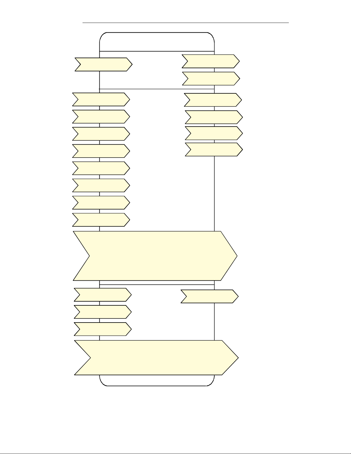
Integration – Global Commands
The following figure shows, which objects from the thermostat, can be monitored and commanded from the BAS frontend.
Figure 1: Global commands from a BAS front-end to a VT7300 series tstat
Integration – Graphic User Interface (GUI) Objects
The following objects should be typically used in a GUI:
nvoSpaceTemp
occupied_heat (nciSetpts);
unoccupied_heat (nciSetpts);
occupied_cool (nciSetpts);
unoccupied_cool (nciSetpts);
nvoSpaceRH
RHsetpoint (nciRHmodel);
nvoOutdoorTemp
nvoDischAirTemp
nviOccManCmd
nvoEffectOccup
heat_output_primary (nvoUnitStatus)
cool_output (nvoUnitStatus)
ServiceAlarm (nvoSccStatus)
FilterAlarm (nvoSccStatus)
WindowOpened (nvoSccStatus)
16
Page 17

Figure 2: Graphical User Interface (GUI) example of a Fan-Coil system
17
Page 18

Configuration Objects
The following SNVT and UNVT should be typically used for configuration purposes:
nciGenOpts;
nciRHmodel;
nciSetpoints;
Wiring Guide
Overview
For clarity we will use the term “Device” to represent any product with an active Echelon network connection, including
TACO and non-TACO controllers.
Summary Specifications:
Parameter Details
Network Wiring 24 to 16AWG, twisted pair
Maximum total wire length
1
1600 feet (500 meters) in free topology
Maximum device-to-device distance 1600 feet (500 meters) in free topology
Polarity Polarity insensitive
Multi-drop Free Topology
Termination for Free Topology Network Segment
Termination for Doubly Terminated Bus Network
One RC network with Ra = 52.3Ω±1%, 1/8W
Two RC network with Ra = 105Ω±1%, 1/8W
Segment
Number of transceivers per segment Up to 64
Baud rate 78000 bits per second
1
Network segment length varies depending on wire type.
Table 1: Summary of Specifications for a TACO ’ LON Network
Network Configuration
The Echelon network is designed to support free topology wiring and will accommodate bus, star, loop or any of these
topologies. Echelon devices can be located at any point along the network wiring.
Figures 3.1 to 3.5 present five different network topologies. The actual termination circuit will vary by application.
18
Page 19

Maximum Number Of Devices
Up to 64 transceivers are allowed per network segment. If your network requires more than 64 transceivers a repeater is
then required to extend your network
19
Page 20

Maximum Cable Length
The maximum length of a chain is related to its transmission speed. The longer the chain, the slower the speed.
Using proper cable, Echelon supports a baud rate of 78 kilobits per second for distances up to 1600-ft (500 m) in free
topology and 8800 ft (2700 m) in bus topology with double terminations.
If you require a maximum network length of more than 1600-ft (500 m) or 8800 ft (2700 m), then a repeater is
required to extend the network.
Repeater
In the event that the limits on the number of transceivers or total wire distance are exceeded, a physical layer
repeater can be added to interconnect two or more network segments. A repeater will double the overall channel
capability, including node count and network extent, but not bandwidth. Note that only one physical layer repeater
should be placed in series between any two nodes on a channel. If additional cabling or network bandwidth is
required, then a LonWorks Router should be used in place of a repeater.
Terminators
Echelon network segments requires termination for proper data transmission performance. The type of terminator varies
depending on whether shielded or unshielded cable is used. Free topology and Bus networks also differ in their
termination requirements. The following sections describe the various terminators and terminations procedure.
Free Topology Network Segment
In a free topology segment, only one termination is required and may be placed anywhere on the free topology
segment. There are two choices for the termination:
1. RC network with Ra = 52Ω±1%, 1/8W
2. LPI-10 Link Power Interface, with jumper at “1 CPLR” setting.
Doubly Terminated Network Segment
In a doubly terminated bus topology, two terminations are required, one at each end of the bus. There are two
choices for each termination:
1. RC network with Ra = 105Ω±1%, 1/8W
2. LPI-10 Link Power Interface, with jumper at “2 CPLR” setting.
Only one LPI-10 interface is supported per segment. The other terminator must be an RC-type.
Grounding Shielded Twisted Pair Cable
When using Shielded Twisted Pair, terminate the twisted pair as listed in the previous section and ground the
cable shield by using a capacitor, to tie the shield to earth ground, and a large-value resistor to bleed off any
static charge on the shield. Tying the shield to earth ground through a capacitor will avoid DC and 50/60Hz
ground paths from being formed through the shield. Typical values for resistor and capacitor are as follows:
Capacitor = 0.1μF, 10%, Metalized Polyester, ≥ 100V
Resistor = 470kΩ, 1/4W, ±5%
The cable shield should be grounded at least once per segment, and preferably at each node. Grounding the
shield at every node will assist in suppressing 50/60Hz standing waves.
20
Page 21

Network adapter
Although network connections are polarity insensitive, it is good practice to keep polarity consistent throughout the entire
site. Figure 4 shows a network connection example and the location of the Status LED. This Status LED may help to
troubleshoot network problems.
Figure 4: Network connections and location of the Status LED on a LON module
Table 2 shows the different possibilities with the Status LED behaviour of the LON module.
Condition of the Status LED Explanation
Continuously ON The device has no application loaded in its memory and is
Un-configured
Flashing at a rate of 1/2Hz The device has an application loaded in its memory but is
Un-configured. When a device is in the un-configured state, it
does not know which devices to communicate with. A
network management tool is used to logically bind the node
to another in a LonWorks network.
Continuously OFF The device has an application loaded into its memory and is
bound onto a LonWorks network.
Table 2: Status LED condition
Software Files
XIF: When binding a node onto the network, an XIF file is needed. The XIF file has information that is used by the network
management tool to help ease the installation and maintenance process of a node. It is also used for offline configuration
of the node.
APB and NXE: When running an application program associated with a XIF file, an APB or NXE file is needed. Please
note that the thermostats have the APB file already flashed from the factory.
Device Resource File (DRF): When a LON network management tool is used; a DRF file must be installed. DRF files are
needed to display special manufacturer defined variables or configurations correctly.
• Please note that all release notes for the XIF, APB & NXE software files will be included under the
following folder name on your hard drive: C:\LonWorks\Import\Viconics. The name of the file is:
VT7xxxReadme.txt
Plug-Ins File: Plug-Ins simplify start-up, maintenance, configuration and reduce the installation effort.
• Please note that all release notes for Plug-Ins files will be included under the following folder name on
your hard drive: C:\LonWorks\Plug-Ins\Viconics\VT7xxx. The name of the file is: Readme.txt.
• All the latest software files can be downloaded from VICONICS’ web site at
www.viconics.com.com
21
Page 22

RoHS & Non-RoHS APB and NXE Files
In July of 2006, new APB and NXE files where introduced to support new RoHS compliant components from Echelon
Corporation. Those APB and NXE software revisions are not backward compatible and some care and attention
must be taken to assure you are utilizing the correct revision during the commissioning procedure. Please note that the
thermostats already have the proper file flashed from the factory.
In order to differentiate non-RoHS and RoHS software, a new PID has been issued for each new RoHS software as
shown in Figure 5.
Your LNS systems already have a built in protection against firmware mismatch and will refuse any upload from nonRoHS software to a RoHS device or vice-versa. The PID change has been instituted in order to prompt an
“incompatibility” message from your Niagara based system.
Figure 5: RoHS and Non-RoHS Marking and Program IDs
XIF, APB and NXE File Names and Corresponding PIDs
Used on thermostat XIF file names APB / NXE file
names
Non-RoHS VT7200 / VT7300 Series T7X-FC.XIF T7X-FC.APB 80:00:C5:55:00:04:04:0B
RoHS VT7200 / VT7300 Series T7X-FCr.XIF T7X-FCr.APB 80:00:C5:55:00:04:04:1B
RoHS PIR VT7200 / VT7300 Series ** T7X-FC-PIR.XIF T7X-FC-PIR.APB 80:00:C5:55:00:04:04:1D
** Please note that all new PIR ready thermostat series of the VT7200 / VT7300 thermostat family will use the latest
released files to properly use all the new advanced occupancy functions associated with a local PIR accessory cover
installed on the thermostat.
Associated PID
22
Page 23

Device Identification
An Echelon device has a unique mechanism to identify itself, the Neuron ID, which is obtained during commissioning.
There are two ways of getting the Neuron ID: with a Service Pin or manually.
Service PIN
The service pin is used to identify the device at commissioning. By pressing simultaneously the “Up” button and the
“Down” button located on the keypad interface of a VT7300 device, the program ID and the Neuron ID (LonWorks Unique
ID) contained in the device are transmitted to the commissioning or service tool. The Status LED will blink when the
device accepts the Service Pin command.
Figures 6 and 7 show an example of a Service PIN request made through a commissioning tool
Figure 6: Service Pin request through a commissioning tool
Figure 7: Service Pin request through a commissioning tool
23
Page 24

Manual Identification
Neuron ID of a device can also be entered manually through a commissioning or service tool. Neuron ID should be
located on the Echelon chip of the device being commissioned.
Figure 8 shows an example of a Manual Neuron ID request made through a commissioning tool.
Figure 8: Manual Neuron ID request
Tips And Things You Need To Know
In order to operate nviAuxOut (auxiliary output) from the network, Aux contact configuration (Auxcont nciGenOpt)
needs to be set as “Network Controlled”;
If the heartbeat is lost, the module will release the network sensor value for the Room Temperature (nviSpaceTemp)
and the Outdoor Temperature (nviOutdoorTemp);
The SeqOpera value (Sequence of Operation) depends on the nviHeatCool value and nviAuxHeatEnable value. See
note 1 on page 15 for all the details;
Troubleshooting Section
Error / Trouble
Possible Cause Solution
Condition
Thermostat does not
come online
The LON network has too many
devices.
Do not exceed the maximum number of
devices and maximum length allowed
by the EIA-485 specifications.
Too many devices were installed
without any repeaters.
Repeaters need to be installed as
specified in this document.
The LON cable runs are broken Locate the break and correct wiring
The thermostat does not have power Apply power to the thermostat
Document Control
Document Name: ITG-VT7300-PIR-LON E06
Document Filename: ITG-VT7300-PIR-LON E06.pdf
Revision Date Changes
01 January 4, 2006 Created to coincide with release of the VT7300 as a LonMark certified product.
02 April 5, 2006 Updated the DRF files section and removed any application guide reference
03 July 11, 2006 Modified the Software Files section and added the RoHS / Non-RoHS section
04 Aug 15, 2006 Modified Note 1 on page 15
05 Nov 21, 2007 Added modifications required for PIR support to the new VT73xxX5xxxE release
06 Jan 21, 2008 Added additional modifications required for PIR support
24
Page 25

Do it Once. Do it Right.
®
LIMITED WARRANTY STATEMENT
A
y
Taco, Inc. will repair or replace without charge (at the company’s option) any product or part which is proven defective under normal use within three
(3) years from the date of start-up or three (3) years and six (6) months from date of shipment (whichever occurs first).
In order to obtain service under this warranty, it is the responsibility of the purchaser to promptly notify the local Taco stocking distributor or Taco in
writing and promptly deliver the subject product or part, delivery prepaid, to the stocking distributor. For assistance on warranty returns, the
purchaser may either contact the local Taco stocking distributor or Taco. If the subject product or part contains no defect as covered in this warranty,
the purchaser will be billed for parts and labor charges in effect at time of factory examination and repair.
ny Taco product or part not installed or operated in conformity with Taco instructions or which has been subject to misuse, misapplication, the
addition of petroleum-based fluids or certain chemical additives to the systems, or other abuse, will not be covered by this warranty.
If in doubt as to whether a particular substance is suitable for use with a Taco product or part, or for any application restrictions, consult the
applicable Taco instruction sheets or contact Taco at [401-942-8000].
Taco reserves the right to provide replacement products and parts which are substantially similar in design and functionally equivalent to the
defective product or part. Taco reserves the right to make changes in details of design, construction, or arrangement of materials of its products
without notification.
TACO OFFERS THIS WARRANTY IN LIEU OF ALL OTHER EXPRESS WARRANTIES. ANY WARRANTY IMPLIED BY LAW INCLUDING
WARRANTIES OF MERCHANTABILITY OR FITNESS IS IN EFFECT ONLY FOR THE DURATION OF THE EXPRESS WARRANTY SET FORTH
IN THE FIRST PARAGRAPH ABOVE.
THE ABOVE WARRANTIES ARE IN LIEU OF ALL OTHER WARRANTIES, EXPRESS OR STATUTORY, OR ANY OTHER WARRANTY
OBLIGATION ON THE PART OF TACO.
TACO WILL NOT BE LIABLE FOR ANY SPECIAL, INCIDENTAL, INDIRECT OR CONSEQUENTIAL DAMAGES RESULTING FROM THE USE OF
ITS PRODUCTS OR ANY INCIDENTAL COSTS OF REMOVING OR REPLACING DEFECTIVE PRODUCTS.
This warranty gives the purchaser specific rights, and the purchaser may have other rights which vary from state to state. Some states do not allow
limitations on how long an implied warranty lasts or on the exclusion of incidental or consequential damages, so these limitations or exclusions ma
not apply to you.
TACO INC., 1160 Cranston Street, Cranston, RI 02920 Telephone: (401) 942-8000 FAX: (401) 942-2360.
Taco (Canada), Ltd., 6180 Ordan Drive, Mississauga, Ontario L5T 2B3. Telephone: 905/564-9422 FAX: 905/564-9436.
Visit our web site at: http://www.taco-hvac.com
Printed in USA
Copyright 2008
TACO, Inc.
25
 Loading...