

Page 1

Application Guide
PSU1 Pump Sequencing Unit
Self-Contained Interoperable Controller Model UCP-1
505-012
SUPERSEDES: New
Plant ID: 001-4090
Table of Contents
PSU1 . . . . . . . . . . . . . . . . . . . . . . . . . . . . . . . . . . . . . . 3
Overview . . . . . . . . . . . . . . . . . . . . . . . . . . . . . . . . . 3
Features. . . . . . . . . . . . . . . . . . . . . . . . . . . . . . . . . . 3
Purpose of This Guide . . . . . . . . . . . . . . . . . . . . . . . . . 3
Representations and Warranties . . . . . . . . . . . . . . . . . 3
Applicable Documentation . . . . . . . . . . . . . . . . . . . . . . 4
Installation Instructions . . . . . . . . . . . . . . . . . . . . . . . . . 4
Precautions . . . . . . . . . . . . . . . . . . . . . . . . . . . . . . . 4
General . . . . . . . . . . . . . . . . . . . . . . . . . . . . . . . . . .4
Static Electricity . . . . . . . . . . . . . . . . . . . . . . . . . . . . 4
Location . . . . . . . . . . . . . . . . . . . . . . . . . . . . . . . . . . 5
FCC Compliance . . . . . . . . . . . . . . . . . . . . . . . . . . . 5
Before Installing . . . . . . . . . . . . . . . . . . . . . . . . . . . . . . 5
About this Document . . . . . . . . . . . . . . . . . . . . . . . . 5
Inspecting the Equipment . . . . . . . . . . . . . . . . . . . . 5
What is Not Included with this Equipment . . . . . . . . 5
Equipment Location . . . . . . . . . . . . . . . . . . . . . . . . .5
Selecting a Power Source . . . . . . . . . . . . . . . . . . . . 6
Installation . . . . . . . . . . . . . . . . . . . . . . . . . . . . . . . . . . 6
Mounting the Device . . . . . . . . . . . . . . . . . . . . . . . .6
Routing Cabling to the Device . . . . . . . . . . . . . . . . . 7
Grounding the Device . . . . . . . . . . . . . . . . . . . . . . .8
Wiring Information . . . . . . . . . . . . . . . . . . . . . . . . . . . . 8
Connecting Input Devices . . . . . . . . . . . . . . . . . . . 11
Connecting Output Devices . . . . . . . . . . . . . . . . . .12
Other Connections . . . . . . . . . . . . . . . . . . . . . . . . . 12
Specifications . . . . . . . . . . . . . . . . . . . . . . . . . . . . . . . 13
Electrical . . . . . . . . . . . . . . . . . . . . . . . . . . . . . . . . 13
Mechanical. . . . . . . . . . . . . . . . . . . . . . . . . . . . . . . 14
EFFECTIVE: August 10, 2012
Application Description. . . . . . . . . . . . . . . . . . . . . . . . 14
Sequence of Operation . . . . . . . . . . . . . . . . . . . . . . . 15
Operational Modes . . . . . . . . . . . . . . . . . . . . . . . . 15
Auto Flow Recovery Mode. . . . . . . . . . . . . . . . . . . 16
Modulation . . . . . . . . . . . . . . . . . . . . . . . . . . . . . . . 19
Lead Pump Select . . . . . . . . . . . . . . . . . . . . . . . . . 19
Constant Circulation . . . . . . . . . . . . . . . . . . . . . . . 19
Low Supply Temperature Circulation. . . . . . . . . . . 19
Pump Exercising . . . . . . . . . . . . . . . . . . . . . . . . . . 19
Commissioning . . . . . . . . . . . . . . . . . . . . . . . . . . . 20
Alarms . . . . . . . . . . . . . . . . . . . . . . . . . . . . . . . . . . 20
Controller Identification . . . . . . . . . . . . . . . . . . . . . . . 20
Network Inputs. . . . . . . . . . . . . . . . . . . . . . . . . . . . 21
Inputs. . . . . . . . . . . . . . . . . . . . . . . . . . . . . . . . . . . 22
Outputs . . . . . . . . . . . . . . . . . . . . . . . . . . . . . . . . . 22
Configuration . . . . . . . . . . . . . . . . . . . . . . . . . . . . . 22
Alarms . . . . . . . . . . . . . . . . . . . . . . . . . . . . . . . . . . 25
Troubleshooting . . . . . . . . . . . . . . . . . . . . . . . . . . . . . 25
Diagnostic LEDs . . . . . . . . . . . . . . . . . . . . . . . . . . 25
Troubleshooting Tips . . . . . . . . . . . . . . . . . . . . . . . 26
© 2012 Taco Electronic Solutions, Inc. 1
Page 2

iWorx® PSU1
THIS PAGE LEFT BLANK INTENTIONALLY
2 505-012, Effective: August 10, 2012
© 2012 Taco Electronic Solutions, Inc.
Page 3

iWorx® PSU1
PSU1
The PSU1 pump sequencing unit is a stand-alone microprocessor-based controller for radiant heating or cooling applications.
Overview
The PSU1 is a compact, microcontroller-based controller for support of radiant applications with pump sequencing
needs. It controls the pump sequences, rotates and stages the pumps according to the programmed mode, maintains
desired differential temperature (Delta T), and generates flow alarms if no flow is detected.
The controller is based on LONWORKS® networking technology. The controller can be networked to a higher-level control
system for monitoring and control applications.
Features
• Control of two primary pumps with four control modes
• Standby pump operation with manually selectable lead pump
• Equal runtime operation with adjustable run time
• Two-stage digital control or single-stage modulated control (with digital enable) based on an adjustable primary
loop temperature differential
• Automatic configuration with a Local Control Interface (LCI) touchscreen
• Alarm/Event reporting
• LONWORKS® interface to building automation systems
PURPOSE OF THIS GUIDE
The iWorx® PSU1 Application Guide provides application information for the PSU1 Controller.
The reader should understand basic HVAC concepts, intelligent environmental control automation, and basic LON-
WORKS networking and communications. This application manual is written for:
• Users who engineer control logic
• Users who set up hardware configuration
• Users who change hardware or control logic
• Technicians and field engineers
REPRESENTATIONS AND WARRANTIES
This Document is subject to change from time to time at the sole discretion of Taco Electronic Solutions, Inc. All
updates to the Document are available at www.taco-hvac.com. When installing this product, it is the reader’s responsibility to ensure that the latest version of the Document is being used.
iWorx® products shall only be used for the applications identified in the product specifications and for no other purposes. For example, iWorx® products are not intended for use to support fire suppression systems, life support systems, critical care applications, commercial aviation, nuclear facilities or any other applications where product failure
could lead to injury to person, loss of life, or catastrophic property damage and should not be used for such purposes.
Taco Electronic Solutions, Inc. will not be responsible for any product or part not installed or operated in conformity with
the Document and instructions or which has been subject to accident, disaster, neglect, misuse, misapplication, inadequate operating environment, repair, attempted repair, modification or alteration, or other abuse. For further information, please refer to the last page of this Document for the company’s Limited Warranty Statement, which is also issued
with the product or available at www.taco-hvac.com.
505-012, Effective: August 10, 2012 3
© 2012 Taco Electronic Solutions, Inc.
Page 4

iWorx® PSU1
APPLICABLE DOCUMENTATION
See the table below for additional documentation that may be applicable to this controller.
Description Audience Purpose
iWorx® network interface description
document, file name:
iWorx_IDS_117.doc
iWorx® LCI2 Application Guide, Document No. 505-002
http://iWorxWizard.taco-hvac.com – Application Engineers
Additional
Documentation
– Application Engineers
– Installers
– Service Personnel
– Start-up Technicians
– Application Engineers
– Installers
– Service Personnel
– Start-up Technicians
– End user
– Wholesalers
– Contractors
LonWorks FTT-10A Free Topology Transceiver User’s Guide, published by Echelon Corporation. It provides specifications and user instructions for the FTT-10A Free Topology Transceiver. See also: www.echelon.com/support/documentation/manuals/transceivers.
Provides information concerning the iWorx®
network interface.
Provides instructions for setting up and using
the iWorx® Local Control Interface.
An on-line configuration and submittal package
generator based on user input. Automatically
generates bill of materials, sequence of operations, flow diagrams, wiring diagrams, points
and specifications.
INSTALLATION INSTRUCTIONS
Precautions
General
CAUTION: This symbol is intended to alert the user to the presence of important installation and mainte-
nance (servicing) instructions in the literature accompanying the equipment.
CAUTION: Risk of explosion if battery is replaced by an incorrect type. Contains lithium type battery; dispose of properly.
WARNING: Electrical shock hazard. Disconnect ALL power sources when installing or servicing this
equipment to prevent electrical shock or equipment damage.
Make all wiring connections in accordance with these instructions and in accordance with pertinent national and local
electrical codes. Use only copper conductors that are suitable for 167 °F (75 °C).
Static Electricity
Static charges produce voltages that can damage this equipment. Follow these static electricity precautions when handling this equipment.
• Work in a static free area.
• Touch a known, securely grounded object to discharge any charge you may have accumulated.
• Use a wrist strap when handling printed circuit boards. The strap must be secured to earth ground.
4 505-012, Effective: August 10, 2012
© 2012 Taco Electronic Solutions, Inc.
Page 5

iWorx® PSU1
Location
Avoid locations where corrosive fumes, excessive moisture, vibration or explosive vapors are present.
Avoid electrical noise interference. Do not install near large contactors, electrical machinery, or welding equipment.
This equipment is suitable for indoor use only. Preferably, or as required by National Electrical Code, the unit is
intended to be installed within an electrical control enclosure. Operate where ambient temperatures do not exceed
140 °F (60 °C) or fall below 32 °F (0 °C) and relative humidity does not exceed 90%, non-condensing.
FCC Compliance
This equipment has been tested and found to comply with the limits for a Class A digital device, pursuant to Part 15 of
the FCC rules. These limits are designed to provide reasonable protection against harmful interference. This equipment can radiate radio frequency energy and, if not installed and used in accordance with the instructions, may cause
harmful interference to radio communications. However, there is no guarantee that interference will not occur in a particular installation. If this equipment does cause harmful interference to radio or television reception, which can be
determined by turning the equipment off and on, the user is encouraged to try to correct the interference by one or
more of the following measures:
• Reorient or relocate the receiving antenna.
• Increase the separation between the equipment and the receiver.
• Connect the equipment to a power source different from that to which the receiver is connected.
• Consult the equipment supplier or an experienced radio/TV technician for help.
You are cautioned that any changes or modifications to this equipment not expressly approved in these instructions
could void your authority to operate this equipment in the United States.
BEFORE INSTALLING
About this Document
The instructions in this manual are for the PSU1 module which supports a liquid source heat pump.
Inspecting the Equipment
Inspect the shipping carton for damage. If damaged, notify the carrier immediately. Inspect the equipment for damage.
Return damaged equipment to the supplier.
What is Not Included with this Equipment
• A power source for the equipment electronics and peripheral devices.
• Tools necessary to install, troubleshoot and service the equipment.
• The screws or DIN rail needed to mount the device.
• Peripheral devices, such as sensors, actuators, etc.
• Cabling, cabling raceway, and fittings necessary to connect this equipment to the power source, FTT-10A network
and peripheral devices.
Equipment Location
Abide by all warnings regarding equipment location provided earlier in this document.
Optimally, the equipment should be installed within a secure enclosure.
505-012, Effective: August 10, 2012 5
© 2012 Taco Electronic Solutions, Inc.
Page 6

iWorx® PSU1
If the equipment is to be installed outdoors, it must be contained within a protective enclosure. The enclosure must
maintain internal temperature and humidity within the ranges specified for this equipment.
The equipment must be installed within 500 feet of all input peripherals (smoke detectors, sensors, etc.) that are connected to the equipment.
Selecting a Power Source
This equipment requires a UL recognized Class 2 external power source (not supplied) to operate. The controller
power input requires a voltage of 24 Volts AC.
To calculate power source current requirements, add the power consumption of all peripheral devices to that of the
controller.
The controller and sensor power supplies can use the same power source. If both are using the same power source,
the loads must have EMF protection. This protection can be integral to the load, or installed in the 24 VAC wiring across
the load’s coil.
To provide necessary RFI and transient protection, the controller’s ground (GND) pin (T40) must be connected to earth
ground or the earth ground of the packaged unit’s enclosure ground. Failure to properly ground the controller may
cause it to exceed FCC limits. Excessive noise could also produce inaccurate sensor data. The power source must be
capable of operating with this connection to ground.
INSTALLATION
Warning: Electrical shock hazard. To prevent electrical shock or equipment damage, disconnect ALL
power sources to controllers and loads before installing or servicing this equipment or modifying any wiring.
Mounting the Device
1.Select a mounting location. Enclosure mounting is recommended.
2.Hold the controller on the panel you wish to mount it on. With a marker or pencil mark the mounting locations on
the panel.
3.Using a small drill bit pre-drill the mounting holes.
4.Using two #6 pan head screws, mount the controller to the panel.
5.Wire the controller (See Routing Cabling to the Device).
6 505-012, Effective: August 10, 2012
© 2012 Taco Electronic Solutions, Inc.
Page 7
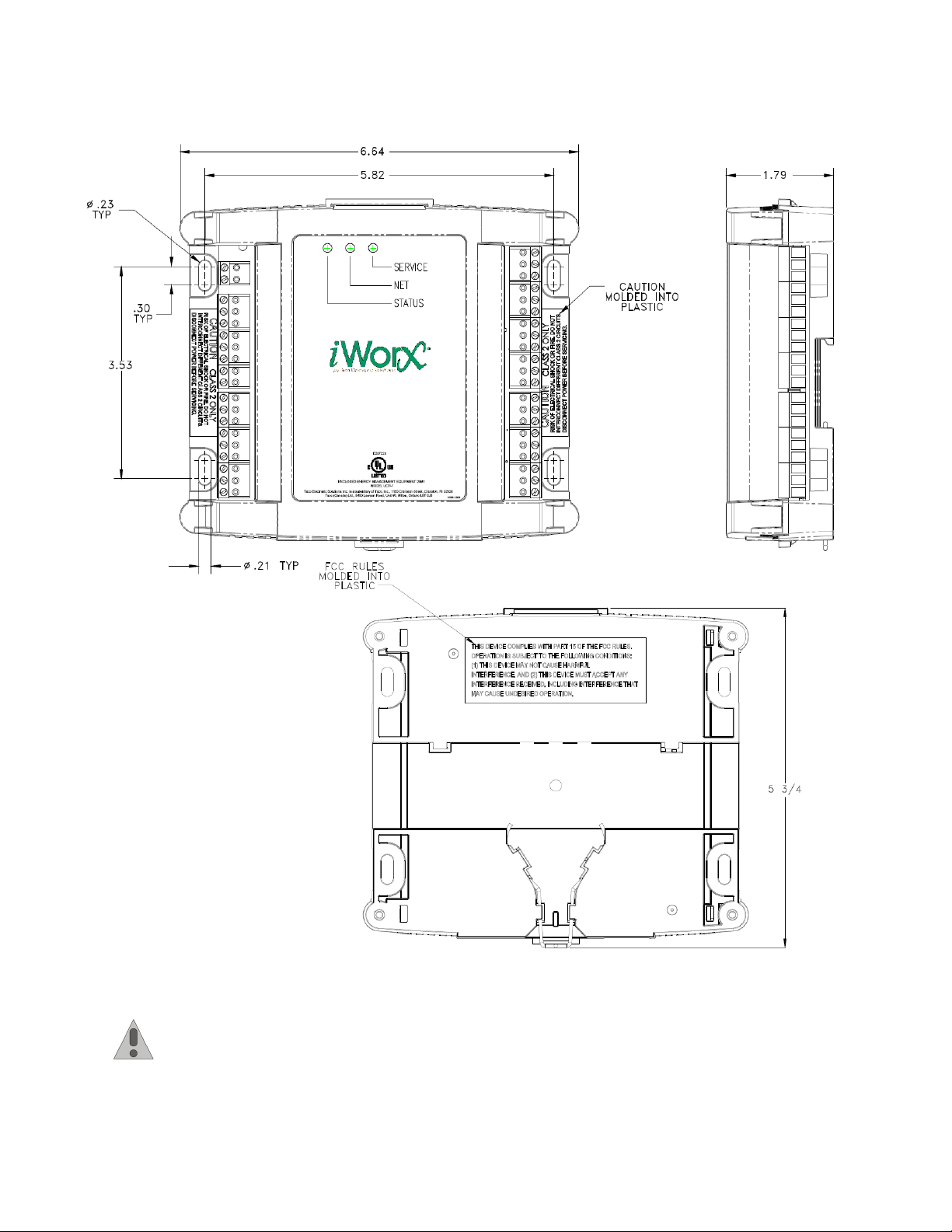
Figure 1: Mounting Dimensions
iWorx® PSU1
Routing Cabling to the Device
Cabling used to connect the power source and cabling used to connect the FTT-10A network must remain
separated within the control enclosure and wiring conduit.
505-012, Effective: August 10, 2012 7
© 2012 Taco Electronic Solutions, Inc.
Page 8
iWorx® PSU1
Grounding the Device
The ground terminal (T40) must be securely connected to earth ground. Failure to properly ground this
equipment will result in improper operation. Improper grounding may also increase the risk of electrical
shock and may increase the possibility of interference with radio/TV reception.
For best performance, connect the power supply common terminal (T38) to the same external point as the
ground terminal (T40).
WIRING INFORMATION
WARNING: Terminals 4, 6, 9, 12, 15, 18, and 38 are connected internally on all PSU1 controllers. Discon-
nect ALL power sources when installing or servicing this equipment to prevent electrical shock or equipment damage.
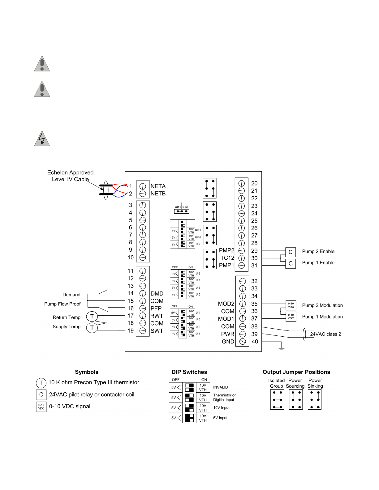
Figure 2: PSU1 Wiring Example - Power Sourcing
8 505-012, Effective: August 10, 2012
© 2012 Taco Electronic Solutions, Inc.
Page 9

Figure 3: PSU1 Wiring Example - Power Sinking
iWorx® PSU1
505-012, Effective: August 10, 2012 9
© 2012 Taco Electronic Solutions, Inc.
Page 10

iWorx® PSU1
Figure 4: PSU1 Wiring Example - Power Isolated
10 505-012, Effective: August 10, 2012
© 2012 Taco Electronic Solutions, Inc.
Page 11

iWorx® PSU1
Connecting Input Devices
The figure below demonstrates typical sensor wiring:
Figure 5:
Precon II or III sensors are wired as a standard thermistor. One terminal is connected to a common pin, the other to the
SWT/RWT input. Dip switches for SWT/RWT inputs using Precon II or III sensors must be configured for VTH input.
Supply Temp (SWT)
To connect the Supply Temp sensor to the unit, attach one wire from the sensor to SWT (T19) and the other wire to the
adjacent common (T18). Please refer to the Wiring Information for the sensor types and the corresponding DIP switch
settings.
This sensor is required for pump staging or modulation.
Precon II or III Wiring
Return Temp (RWT)
To connect the Return Temp sensor to the unit, attach one wire from the sensor to RWT (T17) and the other wire to the
adjacent common (T18). Please refer to the Wiring Information for the sensor types and the corresponding DIP switch
settings.
This sensor is required for pump staging or modulation.
Pump Flow Proof (PFP)
To connect the Pump Flow Proof sensor to the unit, attach one wire from the sensor to PFP (T16) and the other wire to
the adjacent common (T15). This must be a dry contact normally open or closed switch.
Demand (DMD)
To connect the Demand sensor to the unit, attach one wire from the sensor to DMD (T14) and the other wire to the
adjacent common (T15). This must be a dry contact switch.
Setting DIP Switches
Each input has a corresponding pair of DIP switches. The DIP switches are in three black cases with white switches
located near the inputs. While holding the board with the inputs facing down, the pair of dip switches furthest to the right
correspond to the right-most input (SWT), the next pair of dip switches correspond to the next input (RWT) and so on.
505-012, Effective: August 10, 2012 11
© 2012 Taco Electronic Solutions, Inc.
Page 12

iWorx® PSU1
Dip switch pairs must be set properly for each input to operate correctly as shown below:
Figure 6: DIP Switch Settings
NOTE: The dip switches are black boxes with white switches; this drawing is a negative image; the switch
position is shown as black.
Connecting Output Devices
Pump Enable Output (PMP1, PMP2)
The outputs for the Pump Enable must be connected to 24 VAC pilot relays.
• Connect PMP1 (T31) to load. Use TC12 (T30) as common.
• Connect PMP2 (T29) to load. Use TC12 (T30) as common.
Pump Modulated Outputs (MOD1, MOD2)
The modulated outputs can be set to 0-10 V through the control logic. The control signal input of the pump connects to
the 0-10V outputs of the PSU1.
• Connect MOD1 (T37) to load. Use COM (T36) as common.
• Connect MOD2 (T35) to load. Use COM (T36) as common.
Other Connections
Network (LON)
Network wiring must be twisted pair. One network wire must be connected to terminal NETA (T1) and the other network
wire must be connected to terminal NETB (T2). Polarity is not an issue since an FTT-10A network is used for communications.
Power (PWR)
Connect one output wire from a 24 VAC power supply to PWR (T39) and the other output wire from the power supply to
the adjacent common terminal (T38).
Ground (GND)
Terminal GND (T40) must be connected to earth ground. Failure to properly ground this equipment will
result in improper operation. Improper grounding may also increase the risk of electrical shock, and may
increase the possibility of interference with radio and TV reception.
12 505-012, Effective: August 10, 2012
© 2012 Taco Electronic Solutions, Inc.
Page 13

SPECIFICATIONS
Electrical
Inputs
• Cabling: twisted shielded pair, 18 AWG recommended—500 feet max. (152 meters)
• Resolution: 10 bit
Demand
• Dry Contact
• Normally Open
Flow
• Dry Contact
• Normally Open, Normally Closed
Supply Water Temperature, Return Water Temperature
• Precon Type II or III 10K Thermistor
Outputs
Pump Enable
• 24 Volts AC
• 1 Amp at 50 °C, 0.5 Amps at 60 °C, limited by Class 2 supply
Pump Modulation
• 0 - 10 Volts DC
• 2K Ohm minimum load
iWorx® PSU1
Power
Power Requirements
• 24VAC (20VAC to 28VAC), requires an external Class 2 supply
Power Consumption
• 7.2W with no external loads, maximum limited by the Class 2 supply rating
Recommended Sensor Wire
Cable Type Pairs Details Taco Catalog No.
18AWG 1 Stranded Twisted Shielded Pair, Plenum WIR-018
FTT-10A Network
• Speed: 78KBPS
• 42.4 Volts DC max
• Cabling: Maximum node-to-node distance: 1312 feet (400 meters)
• Maximum total distance: 1640 feet (500 meters)
Cable Type Pairs Details Taco Catalog No.
Level 4 22AWG (0.65mm) 1 Unshielded, Plenum, U.L. Type CMP WIR-022
For detailed specifications, refer to the FTT-10A Free-Topology Transceiver User’s Guide published by Echelon Corporation (www.echelon.com/support/documentation/manuals/transceivers).
505-012, Effective: August 10, 2012 13
© 2012 Taco Electronic Solutions, Inc.
Page 14

iWorx® PSU1
Mechanical
Housing
• Dimensions: 5.55” (141mm) high, 6.54” (166 mm) wide, 1.75” deep (44 mm)
• ABS
Weight
• Controller Weight: 0.70 pounds (0.32 kilograms)
• Shipping Weight: 1.0 pounds (0.46 kilograms)
Electronics
• Processor: 3150 Neuron 10 MHz
• Flash: 48 Kilobytes
• SRAM: 8 Kilobytes
• Termination: 0.197” (5.0 mm) Pluggable Terminal Blocks, 14-22 AWG
Environmental
• Temperature: 32 °F to 140 °F (0 °C to 60 °C)
• Humidity: 0 to 90%, non-condensing
Agency Listings
• UL Listed for US and Canada, Energy Management Equipment PAZX and PAZX7.
Agency Compliances
• FCC Part 15 Class A
APPLICATION DESCRIPTION
The PSU1 is intended for control of two primary pumps and can either extend the features of an iWorx® Series boiler
controller, or can operate as a stand-alone controller.
Figure 7: Typical Application
14 505-012, Effective: August 10, 2012
© 2012 Taco Electronic Solutions, Inc.
Page 15

iWorx® PSU1
Four possible operational modes are provided. The first is Single mode where a lead pump is manually selected via the
LCI. If the lead pump does not provide the required flow as determined by the flow/pressure switch input, then an alarm
is generated. Depending on the Lead Pump Sel setting and pump runtimes, the lag pump may also be turned on. The
second mode, Standby mode, is similar to Single mode with the exception that the lag pump is always started when the
lead pump fails to provide the required flow. The third mode, Equal Runtime Mode, allows for standby operation plus
equal runtime rotation of the two pumps based on a runtime setting on the LCI.
These three modes (Single, Standby and Equal Runtime) also allow the option for Delta T temperature modulation via
digital pump enable and modulated pump output signals. The fourth mode -- 2 Stage mode -- allows for standby operation, plus provides two-stage operation (digital pump control only) of the pumps based on the Delta T of the primary
loop.
NOTE: The Delta T displayed and used for sequencing algorithms is always the absolute value of the Supply - Return Temperature. The controller is indifferent to the sign of the equation result. This behavior promotes automatic changeover between heating and cooling systems at the point where Delta T is 0 °F.
SEQUENCE OF OPERATION
This section describes the detailed sequence of operation for the PSU1 control strategy.
Operational Modes
The four primary modes of operation for sequencing primary pumps are described below.
Table 1: Operational Mode Features
Operational
Mode Setting
Single Pump1, Pump2 No No No Yes (Optional)
Standby Any Yes No No Yes (Optional)
Equal Runtime Any Yes Yes No Yes (Optional)
2 Stage Any Yes No Yes No
Lead Pump Sel
Setting
Lowest Hours Yes, if lag hours >=
Alternating Yes
Standby Failover?
lead
Pump Alternation
During Operation?
Delta T Pump
Staging?
Delta T Modulated
Outputs?
Single Mode
If only one pump is used, or if one pump is unavailable due to servicing, then this mode may be used to disable standby
failover. Whenever the lead primary pump is turned on by the controller and the Enable Alarm setting is not “Disabled”,
the Pump Flow Proof is monitored. If the Pump Flow Proof switch remains open after a configurable delay, the lead
pump is turned off and disabled, the In Alarm? indicator displays “Yes” and an alarm for the lead pump is communicated to the LCI. If the Lead Pump Sel setting is set to “Lowest Hours” and the lag pump has a lower runtime, or if the
Lead Pump Sel setting is set to “Alternating,” then the lag pump is started. If purely single pump operation is desired,
then Operation Mode must be set to “Single” and the Lead Pump Sel setting must be set to either “Pump1” or “Pump2”.
505-012, Effective: August 10, 2012 15
© 2012 Taco Electronic Solutions, Inc.
Page 16

iWorx® PSU1
Standby Mode
In Standby Mode, whenever the lead primary pump is turned on by the controller and the Enable Alarm setting is not
“Disabled”, the Pump Flow Proof is monitored. If the Pump Flow Proof switch remains open after a configurable delay,
the lead pump is turned off and disabled, the lag pump is turned on, and an alarm for the lead pump is communicated
to the LCI. If the Pump Flow Proof switch remains off after another duration of the configurable delay, the lag pump is
turned off and disabled, the In Alarm? indicator displays “Yes” and an alarm for the lag pump is communicated to the
LCI. When either pump is on, the Pump Flow Proof switch continues to be monitored for an open state, and switches
pumps after the configurable delay, if necessary. Unless Flow Recovery Mode is enabled, the controller is locked out
whenever both pumps are disabled. The controller must be reset to enable pumps that have failed.
Equal Runtime Mode
The lead pump is started first and remains on as long as there is a call for it. The first pump runs for the number of
hours specified in the pump settings Max Runtime field. Once the number of hours specified has passed, the sequence
to swap the pumps is started.
NOTE: The lead pump may be changed manually at any time by changing the Lead Pump Sel setting.
When changed, the timers used by Equal Runtime mode are reset and the new lead is run for Max Run-
time.
When a swap is needed, the lead pump is placed into a Post Purge state.
NOTE: If modulated pump control is being used, the lead pump decelerates during the post purge period
until it is operating at its minimum speed or the post purge period has expired. The pump ramps down at a
rate defined by Pump Mod Set: Ramp Down.
After the time period specified by Pump Settings: Post Purge Time has elapsed, the lead pump turns off and the lag
pump is turned on.
If Enable Alarm setting is not “Disabled,” the Pump Flow Proof switch continues to be monitored for an open state, and
switches pumps after the configurable delay, if necessary. The pumps are not rotated if one of the pumps has failed.
This mode also includes all of the capabilities of Standby Mode.
Two Stage Mode
The lag pump may be set to operate as a second stage pump to meet increased demand. When the lead pump is operating and Delta T exceeds the amount specified in Temperature Differential for at least two minutes, the lag pump is
started. When Delta T is reduced to less than 5°F below the Temperature Differential for at least two minutes, the lag
pump is turned off.
NOTE: Delta T is always converted to an absolute value before comparing against the Temperature Differ-
ential setting.
Two stage operation may be disabled by changing the Operational Mode from “2 Stage” to another operating mode.
This mode is also disabled whenever one of the pumps has failed.
When Operational Mode is set to “2 Stage,” Operational Type is automatically set to “Switching.” Modulation is not
available in this mode.
This mode also includes all of the capabilities of Standby Mode.
Auto Flow Recovery Mode
Auto Flow Recovery Mode augments all modes that include Standby Mode capabilities. It is intended to prevent controller lockout in the event of a faulty Pump Flow Proof switch or in the event that pump motors temporarily do not
respond to the PSU1 control signals.
The Auto Flow Recovery sequence begins after Standby Mode has disabled the lag pump. When Auto Flow Recovery
is active, the controller operates both pumps simultaneously. The controller is able to restart itself and resume normal
operation once flow is detected.
16 505-012, Effective: August 10, 2012
© 2012 Taco Electronic Solutions, Inc.
Page 17

iWorx® PSU1
All operating modes that support standby failover normally switch off pumps that fail to satisfy the flow proof input. If
Flow Recovery is enabled both pump outputs will be energized after a 30 second delay. If modulated outputs are configured, modulation levels are fixed to the minimum "On" level specified under the Pump Mod Set: On settings. Pump
runtime is not accumulated at any point in time while Flow Recovery is active.
Flow is monitored while the controller is operating in Flow Recovery mode. An automatic restart occurs during Flow
Recovery mode if automatic restarts are remaining and the controller detects flow for the amount of time specified by
the Flow Delay setting. The Restarts Left output value indicates the number of automatic restarts remaining. The number of automatic restarts is configurable under the Auto Recovery: Number Restarts setting. To prevent the controller
from restarting in Flow Recovery Mode, set Auto Recovery: Number Restarts setting to "0."
An automatic restart succeeds when a single pump is able to satisfy the flow proof sensor. Once an automatic restart
succeeds, a timer is started. The Restarts Left output value is restored to the Auto Recovery: Number Restarts setting
after one day of successful operation. Each automatic restart resets this timer to zero and another day of successful
operation must occur before the Restarts Left output value is restored.
While in Flow Recovery Mode, the Flow Recovery Mode output on the LCI displays "Yes".
When Flow Recovery Mode displays "Yes" and Restarts Left displays "0" the controller is in Flow Recovery mode, but
no longer able to attempt an automatic reset. Flow is not monitored. Since a successful automatic restart is required
before Restarts Left is restored, the controller operates in this state indefinitely until flow issues are resolved and a
manual controller reset is performed. Both outputs will be energized in accordance with demand inputs regardless of
the flow reading.
The controller will leave Flow Recovery Mode when an automatic restart occurs, the controller is manually reset, or
commissioning mode is used. While in Flow Recovery Mode, pump outputs are energized corresponding to the
demand input. Cycling demand causes controller outputs to turn on or off, but does not cause the controller to leave
Flow Recovery Mode.
The Pump Settings: Post Purge Time is enforced when demand input changes from active to inactive in Flow Recovery
mode. Both pump outputs are energized until the post purge time is complete.
In order to enable the Flow Recovery sequence, the following conditions must be met:
• Pump Settings: Operational Mode must be set to a mode other than "Single".
• Enable Alarm must be set to "Switch (Open)" for monitoring of a normally open flow switch or "Switch (Closed)" for
monitoring of a normally closed flow switch.
• Auto Recovery: Enable must be set to "On."
505-012, Effective: August 10, 2012 17
© 2012 Taco Electronic Solutions, Inc.
Page 18

iWorx® PSU1
Figure 8: Example Auto Flow Recovery Sequence
NOTE: This flow chart depicts Auto Flow Recovery behavior in Standby Mode with an active demand
input. Unrelated operational behavior has been intentionally omitted.
18 505-012, Effective: August 10, 2012
© 2012 Taco Electronic Solutions, Inc.
Page 19

iWorx® PSU1
Modulation
Pump modulation is available in Single, Standby and Equal Runtime modes.
To enable the modulated outputs, set Pump Settings: Operational Type to “Modulating.” Under Pump Mod Set, configure the modulation settings according to the specific pump in use.
NOTE: Out Min and Out Max must be specified. These values configure the voltage range of the modu-
lated output. The min and max default to zero volts and must be set properly before the physical output will
be able to modulate pump speed.
When modulation is enabled, the pump's Pump Enable Output and Pump Modulated Output are both active whenever
a pump is on. The Pump Modulated Output adjusts the pump's speed to maintain the desired Delta T.
NOTE: Delta T is always converted to an absolute value before comparing against the Temperature Differ-
ential setting.
A larger Delta T value than the Temperature Differential setting acts to accelerate the pump; a smaller value than the
setting acts to decelerate the pump.
Lead Pump Select
The lead pump may be changed manually at any time by changing the Lead Pump Sel setting.
NOTE: When Lead Pump Sel setting is changed, the timers used by Equal Runtime mode are reset.
The lead pump may be set to a specific pump, the pump with lowest hours, or alternating.
The specific pump choices are “Pump 1" or “Pump 2."
The “Lowest Hours” setting automatically chooses the pump with lowest runtime hours when there is a call to run. If
both pumps have equal runtimes, then preference is given to Pump 1.
If the “Alternating” setting is chosen, then the lead pump alternates on each call to run.
Constant Circulation
If the Const Pump Circ setting is “On,” a primary pump remains on continuously, regardless of demand.
2 Stage Mode: When Constant Circulation is “On” and the controller is in 2 Stage Mode, pump staging occurs according to the water temperature differential and user settings.
Pump Modulation and Other Modes: When Constant Circulation is set to “On” and the controller Operating Type is set
to “Modulating,” pump speed is modulated according to the water temperature differential and user settings.
Low Supply Temperature Circulation
If the Low Temp Setting is greater than 0.01°F, the Low Supply Temperature circulation feature is enabled. When the
Supply Temperature falls below the setpoint, the lead pump is turned on.
2 Stage Mode: No staging occurs when Low Supply Temp Circulation is active.
Pump Modulation and Other Modes: Pump speed is fixed at the minimum speed when Low Supply Temp Circulation is
active.
Pump Exercising
If Pump Settings: Pump Exercise is “On,” the pumps run sequentially for 15 seconds every week during periods of inac-
tivity. There is a 1-second delay between pumps.
Pump Modulation: Pump speed is fixed at the minimum speed when pumps are exercising.
505-012, Effective: August 10, 2012 19
© 2012 Taco Electronic Solutions, Inc.
Page 20

iWorx® PSU1
Commissioning
Either pump may be commissioned at any time by means of the Commissioning: Pump 1 Comm or Commissioning:
Pump 2 Comm setting. To turn the pump on, set the switch to “Enable.” To turn the pump off, set the switch to “Disable.”
To resume automatic operation, set the switch to “Auto.”
When pump 1 or pump 2 is enabled in this manner, the pump's modulated output is also set to the speed setting specified in the Commissioning: Pump 1 Mod or Commissioning: Pump 2 Mod setting.
NOTE: Care should be taken to ensure that the Pump 1 Mod or Pump 2 Mod setting is acceptable before
changing the Pump 1 Comm or Pump 2 Comm field to “Enable.”
Alarms
Circulation Pump Failed Alarm
The Pump Flow Proof is monitored whenever the lead primary pump is turned on by the controller. If the Pump Flow
Proof switch remains open after a configurable delay and Enable Alarm is not set to “Disabled,” a Circulation Pump
Failed Alarm is communicated to the LCI.
Dual Pump Failure
When both pumps have failed, a Dual Pump Failure alarm is communicated to the LCI. A dual pump failure alarm
occurs when:
• Two pumps have failed and Auto Flow Recovery Mode is not configured.
• Two pumps have failed, Flow Recovery is active and flow has not been detected for twice the duration configured
under Flow Delay.
Circulation Water Temp alarms
A temperature alarm is communicated to the LCI under the following conditions:
• Circulation Supply Water Temp High
• Circulation Supply Water Temp Low
• Circulation Return Water Temp High
• Circulation Return Water Temp Low
A “Temp High” alarm is generated when measured water temperature exceeds the limit defined in Water Temp Alm:
High Limit. A Temp High alarm returns to normal when the water temperature falls below the High Limit minus 1°F.
A “Temp Low” alarm is generated when measured water temperature is below the limit defined in Water Temp Alm:
Low Limit. A Temp Low alarm returns to normal when the water temperature rises above the Low Limit plus 1°F.
Circulation alarms are disabled when both Water Temp Alm: High Limit and Water Temp Alm: Low Limit are set to 32
°F.
CONTROLLER IDENTIFICATION
To register the controller with the LCI, press the service pin on the controller once it is properly installed and the LCI is
active on the network.
Once the PSU1 is properly installed and recognized by the LCI, the LCI can be used to configure the settings of the
controller. This section describes the commands available on the LCI for configuration of the PSU1, and the meanings
and default values for controller parameters. For more information on using the LCI, see the iWorx® LCI Application
Guide.
20 505-012, Effective: August 10, 2012
© 2012 Taco Electronic Solutions, Inc.
Page 21

iWorx® PSU1
Network Inputs
The PSU1 allows a network manager to write to Network Input Variables for the purpose of overriding the configuration,
operation and outputs of the PSU1. The network input variables are listed below.
Values written to NVIs have absolute priority over any other controller operation.
• nviOccCmd is a legacy, unused network variable. Overriding this variable does not affect controller operation.
• nviResetRuntime is a command to reset the pump runtimes displayed on the web interface. If the value sent is 0,
then no reset occurs; if the value sent is 1, then the runtimes are reset.
• nviSysTime is a time stamp to set the date and time. Writing to this variable changes the time on the device and
affects all time-related functions such as schedules.
• nviOutOverride is a structure (defined below) that overrides the digital and analog hardware outputs on the PSU1.
These values allow the network controller to directly control the analog and digital outputs of the board.
NOTE: the PSU1 makes no attempt to interpret the outputs; assigning meaningless outputs may have
unpredictable results.
Network Variable Inputs (NVIs)
Internal Variable
Name
nviOccCmd SNVT_occupancy N/A Legacy; not used
nviResetRuntime SNVT_lev_disc 0 = no reset
nviSysTime SNVT_time_stamp Date/Time System time
nviOutOverride Structure Structure Output override
Format Range Description
1 = reset runtimes
Output Override Structure (NVI)
Name Type/Range Default Description
digOut[8] Unsigned Byte:
0=OFF
1=ON
0xFF=no override
aOut[4] SNVT_lev_percent:
0% to 100%
32767=no override
fpOut[4] SNVT_lev_percent N/A Not used
0xFF
0xFF
0xFF
0xFF
0xFF
0xFF
0xFF
0xFF
32767
32767
32767
32767
digOut[0] = TO1 (pin 31)
digOut[1] = TO2 (pin 29)
digOut[2] = TO3 (pin 28)
digOut[3] = TO4 (pin 26)
digOut[4] = TO5 (pin 25)
digOut[5] = TO6 (pin 23)
digOut[6] = TO7 (pin 22)
digOut[7] = TO8 (pin 20)
aOut[0] = AO 0 (pin 37)
aOut[1] = AO 1 (pin 35)
aOut[2] = AO 2 (pin 34)
aOut[3] = AO 3 (pin 32)
Resets the pump runtimes
505-012, Effective: August 10, 2012 21
© 2012 Taco Electronic Solutions, Inc.
Page 22

iWorx® PSU1
Inputs
The Inputs screen displays the current values of the PSU1’s inputs. These values cannot be changed.
Name Range Description
Outside Temp -30 to 230 °F (-34.4 to 110 °C) The outside air temperature as
reported by the networked ASM2
Supply Temp -30 to 230 °F (-34.4 to 110 °C) Primary supply water temperature
Return Temp -30 to 230 °F (-34.4 to 110 °C) Return water temperature
Demand Off, On Status of the demand
Flow Switch Off, On Status of the Pump Flow Proof
switch
Delta T 0 to 260 °F (0 to 144.4 °C) Differential temperature between
the supply and return temperature
readings
Outputs
The Outputs screen displays the current values of the PSU1’s outputs. These values cannot be changed.
Name Range Description
Output Status Structure as defined in a table below General pump status
Pump 1 Adjust Structure as defined in a table below Pump 1 commissioning and runtime
Pump 2 Adjust Structure as defined in a table below Pump 2 commissioning and runtime
Pump 1 Modulation 0 to 100% Pump 1 modulation level
Pump 2 Modulation 0 to 100% Pump 2 modulation level
Restarts Left 0 to 4 Number of Auto Flow Recovery
Restarts remaining.
Output Status
Name Range Description
Pump #1 Off, On Status of pump 1
Pump #2 Off, On Status of pump 2
In Alarm? No, Yes Alarm status
Low Temp Circ Off, On Low temperature circulation status
Flow Recovery Mode Yes, No Is Flow Recovery Mode active?
Pump 1 Adjust / Pump 2 Adjust
Name Range Description
Commissioning Auto,
Enabled,
Disabled
Runtime 0 to 65535 hours Accumulated pump runtime
Pump commissioning switch state
Configuration
This section describes the settings that can be modified.
22 505-012, Effective: August 10, 2012
© 2012 Taco Electronic Solutions, Inc.
Page 23

iWorx® PSU1
All Settings
This screen displays all of the controller's settings and provides access to edit all parameters from a single screen.
Some parameters (defaulted as Structure) are described in individual tables below.
Setting Range Default Description
Pump Settings Structure N/A General pump settings
Commissioning Structure N/A Pump commissioning settings
Enable Alarm Disabled,
Switch (open),
Switch (closed
Flow Delay 0 to 180 seconds 15 seconds Amount of time to wait without flow before
Thermistor Type PreconII,
PreconIII
Pump Mod Set Structure Pump modulation settings
Low Temp Setting 0.01 to 50 °F 0.01 °F Sets the minimum temperature at which low
Water Temp Alm Structure N/A
Auto Recovery Structure N/A Auto Flow Recovery settings.
Disabled Enables monitoring and alarming associated
with the Pump Flow Proof switch
signaling pump failure
PreconIII Selects the type of thermistor used for supply
and return water temp
temperature circulation activates. If set to
0.01°F, then this feature is disabled.
Pump Settings
This screen displays PSU1 settings related to this topic and allows access to all of these settings from a single screen.
Setting Range Default Description
Operational Mode Standby,
Single,
Equal Runtime,
2 Stage
Const Pump Circ Off, On Off Causes pumps to run continuously, regard-
Lead Pump Sel Pump 1,
Pump 2,
Lowest Hours,
Alternating
Pre Purge Time 0 to 100 seconds 10 seconds Time primary pump runs before starting a
Post Purge Time 0 to 255 minutes 5 minutes Time primary pump runs after the demand is
Max Runtime 1 to 255 hours 168 hours Amount of run time by which the lead pump
Differential Temp 0 to 40 °F (0 to 22.2 °C) 40 °F (22.2 °C) Primary loop Delta T at which the second
Pump Exercise Off, On Off If “On,” pumps are run sequentially for 15
Operational Type Switching,
Modulated
Single Operating sequences of the two pumps
less of demand
Pump 1 Determines the pump selection method to
use when a new pump must be started.
boiler stage (must be in sync with the BLMC)
to allow accurate temperature measurement.
off to dissipate heat and allow pump speed to
return to a minimum value.
exceeds the lag pump before swapping lead
and lag.
pump is turned on or the desired primary loop
Delta T in single stage modulated mode. The
Absolute value of Delta T is always used
when comparing against this setting.
seconds every week.
Switching Turns on modulated outputs. Not available in
2 Stage mode.
505-012, Effective: August 10, 2012 23
© 2012 Taco Electronic Solutions, Inc.
Page 24

iWorx® PSU1
Commissioning
This screen displays PSU1 settings related to this topic and allows access to all of these settings from a single screen.
Setting Range Default Description
Pump 1 Comm Disable,
Enable,
Auto
Pump 2 Comm Disable,
Enable,
Auto
Pump 1 Mod 0 to 100% 0% Sets the pump 1 modulation level when
Pump 2 Mod 0 to 100% 0% Sets the pump 2 modulation level when
Auto Disable = Off, Enable = On, Auto = Automatic
Operation
Auto Disable = Off, Enable = On, Auto = Automatic
Operation
Pump 1 Comm is set to “Enable”
Pump 2 Comm is set to “Enable”
Pump Mod Set
This screen displays PSU1 settings related to this topic and allows access to all of these settings from a single screen.
Setting Range Default Description
Gain -4 to +5 0 Sets PI loop gain
On 0 to 100% 50% Minimum modulation level while pump is on.
Modulation level will be 0% when pump is off
and will vary between "On" and 100% when
pump is on.
Ramp Up 0.00 to 20.00% 1.00% Ramp up percent per second
Ramp Down 0.00 to 20.00% 0.5% Ramp down percent per second
Out Min 0.0 to 10.0 V 0.0 V Minimum output voltage for modulated pump
outputs corresponding to a modulation level
of 0%.
Out Max 0.0 to 10.0 V 0.0 V Maximum output voltage for modulated pump
outputs corresponding to a modulation level
of 100%.
Water Temp Alm
This screen displays PSU1 settings related to this topic and allows access to all of these settings from a single screen.
Setting Range Default Description
High Limit 32.0 to 212°F
(0 to 100°C)
Low Limit 32.0 to 212°F
(0 to 100°C)
32 °F
(0.0°C)
32 °F
(0.0°C)
Supply and return water temperature high
alarm limit
Supply and return water temperature low
alarm limit
Auto Recovery
This screen displays PSU1 settings related to Auto Flow Recovery and provides access to all of these settings from a
single screen.
Setting Range Default Description
Enable Off, On On Enable Auto Flow Recovery
Number Restarts 0 to 4 4 Maximum number of system restart attempts
24 505-012, Effective: August 10, 2012
© 2012 Taco Electronic Solutions, Inc.
Page 25

Alarms
The table below describes the alarms that the user may encounter and how to reset them.
Alarm Range Alarm Trigger Alarm Reset
Circulation Supply Water
Temp High
Circulation Supply Water
Temp Low
Circulation Return Water
Temp High
Circulation Return Water
Temp Low
Circulation Pump 1 Failed
Alarm
Circulation Pump 2 Failed
Alarm
Dual Pump Failure Normal, Alarm Occurs when both Pump 1 and
Normal, Alarm Supply Temp > Water Temp Alm:
High Limit
Normal, Alarm Supply Temp < Water Temp Alm:
Low Limit
Normal, Alarm Return Temp > Water Temp Alm:
High Limit
Normal, Alarm Return Temp < Water Temp Alm:
Low Limit
Normal, Alarm Occurs when there is Demand,
Pump 1 is selected, Enable Alarm
is not “Disabled,” and no flow has
been detected for Flow Delay seconds.
Normal, Alarm Occurs when there is Demand,
Pump 2 is selected, Enable Alarm
is not “Disabled,” and no flow has
been detected for Flow Delay seconds.
Pump 2 have failed.
Supply Temp < Water Temp Alm:
High Limit - 1°F
Supply Temp > Water Temp Alm:
Low Limit + 1°F
Return Temp < Water Temp Alm:
High Limit - 1°F
Return Temp > Water Temp Alm:
Low Limit + 1°F
Reset the controller (power cycle).
Reset the controller (power cycle).
Reset the controller (power cycle).
iWorx® PSU1
TROUBLESHOOTING
Diagnostic LEDs
The controller has 3 LED indicators. These indicators can aid in troubleshooting equipment operation problems. The
following table lists the functions of the controller’s LEDs in the order they appear from left to right on the unit.
LED Indication
Status – Solid green when running and configured by an LCI (networking)
– Flashing green when running and NOT configured by an LCI (stand-alone)
– Solid red when a fault condition exists (control shut down)
– Blinking Red - the controller has a device failure
– Solid Amber - The controller has not received a LCI ping message in over 10 minutes and is part of a network.
Network – Yellow while the controller is transmitting data onto the FTT-10A network
– Green when there is network activity
– Off when there is no network activity
Service – Illuminated when the service pin is depressed or when a controller gets configured by the LCI.
505-012, Effective: August 10, 2012 25
© 2012 Taco Electronic Solutions, Inc.
Page 26

iWorx® PSU1
Figure 9: PSU1 Controller LEDs
Status Network Service
Troubleshooting Tips
The table below provides solution to some common problems you may encounter.
Problem Solution
Controller is not running and Status
LED is not illuminated.
How do I reset the controller? The controller can be reset by the LCI, or you can cycle power to the controller. Refer to
The Supply or Return Water Temperature thermistor reading is at its maximum or minimum.
Thermistor readings fluctuate rapidly,
sometimes by several degrees.
Under what conditions does the
PSU1 require a reset for normal operation?
No power to controller. Verify the voltage on the controller’s power connector (24 VAC).
the LCI documentation for more information on resetting the controller using the LCI.
The input is either shorted or open.
The controller is not properly grounded. The controller's ground (GND) pin (T40) must
be connected to earth ground. Also ensure that the controller's digital inputs are dry
contacts and that no voltage is being applied or switched to the inputs.
There are three conditions that require a reset:
– Pump 1 Failed alarm
– Pump 2 Failed alarm
– Dual Pump Failure alarm
26 505-012, Effective: August 10, 2012
© 2012 Taco Electronic Solutions, Inc.
Page 27

iWorx® PSU1
Getting Help
Components within an iWorx® controller, sensor, or power supply cannot be field repaired. If there is a problem with a
unit, follow the steps below before contacting your local TES representative or TES technical service.
1.Make sure controllers, sensors, and power supplies are connected and communicating to desired devices.
2.Record precise hardware setup indicating the following:
Version numbers of application software.
Device and/or firmware version number.
A complete description of difficulties encountered.
Notes:
505-012, Effective: August 10, 2012 27
© 2012 Taco Electronic Solutions, Inc.
Page 28

iWorx® PSU1
LIMITED WARRANTY STATEMENT
Taco Electronic Solutions, Inc. (TES) will repair
or replace without charge (at the company's
option) any product or part which is proven
defective under normal use within one (1) year
from the date of start-up or one (1) year and six
(6) months from date of shipment (whichever
occurs first).
In order to obtain service under this warranty, it
is the responsibility of the purchaser to
promptly notify the local TES stocking distributor or TES in writing and promptly deliver the
subject product or part, delivery prepaid, to the
stocking distributor. For assistance on warranty returns, the purchaser may either contact
the local TES stocking distributor or TES. If the
subject product or part contains no defect as
covered in this warranty, the purchaser will be
billed for parts and labor charges in effect at
time of factory examination and repair.
Any TES product or part not installed or operated in conformity with TES instructions or
which has been subject to accident, disaster,
neglect, misuse, misapplication, inadequate
operating environment, repair, attempted
repair, modification or alteration, or other
abuse, will not be covered by this warranty.
TES products are not intended for use to support fire suppression systems, life support systems, critical care applications, commercial
aviation, nuclear facilities or any other applications where product failure could lead to injury
to person, loss of life, or catastrophic property
damage and should not be sold for such purposes.
If in doubt as to whether a particular product is
suitable for use with a TES product or part, or
for any application restrictions, consult the
applicable TES instruction sheets or in the U.S.
contact TES at 401-942-8000 and in Canada
contact Taco (Canada) Limited at 905-564-
9422.
TES reserves the right to provide replacement
products and parts which are substantially similar in design and functionally equivalent to the
defective product or part. TES reserves the
right to make changes in details of design, construction, or arrangement of materials of its
products without notification.
TES OFFERS THIS WARRANTY IN LIEU OF
ALL OTHER EXPRESS WARRANTIES. ANY
WARRANTY IMPLIED BY LAW INCLUDING
WARRANTIES OF MERCHANTABILITY OR
FITNESS IS IN EFFECT ONLY FOR THE
DURATION OF THE EXPRESS WARRANTY
SET FORTH IN THE FIRST PARAGRAPH
ABOVE.
THE ABOVE WARRANTIES ARE IN LIEU OF
ALL OTHER WARRANTIES, EXPRESS OR
STATUTORY, OR ANY OTHER WARRANTY
OBLIGATION ON THE PART OF TES.
TES WILL NOT BE LIABLE FOR ANY SPECIAL, INCIDENTAL, INDIRECT OR CONSEQUENTIAL DAMAGES RESULTING FROM
THE USE OF ITS PRODUCTS OR ANY INCIDENTAL COSTS OF REMOVING OR
REPLACING DEFECTIVE PRODUCTS.
This warranty gives the purchaser specific
rights, and the purchaser may have other rights
which vary from state to state. Some states do
not allow limitations on how long an implied
warranty lasts or on the exclusion of incidental
or consequential damages, so these limitations
or exclusions may not apply to you.
CONTROLS MADE EASY
®
Taco Electronic Solutions, Inc., 1160 Cranston Street, Cranston, RI 02920
Telephone: (401) 942-8000 FAX: (401) 942-2360.
Taco (Canada), Ltd., 8450 Lawson Road, Unit #3, Milton, Ontario L9T 0J8.
Telephone: 905/564-9422. FAX: 905/564-9436.
Taco Electronic Solutions, Inc. is a subsidiary of Taco, Inc.
Visit our web site at: http://www.taco-hvac.com
Printed in the USA iWorx® and iView® are registered trademarks of Taco Electronic Solutions, Inc.
© 2012 Taco Electronic Solutions, Inc. LON, LONWORKS, & LONMARK are trademarks of Echelon Corporation
 Loading...