

Page 1
102-571
Instruction Sheet
SR502/503/504/506-5 Switching Relay
SUPERSEDES: 10/24/24 EFFECTIVE: 12/11/24
Plant ID No. 9300-4099
OVERVIEW:
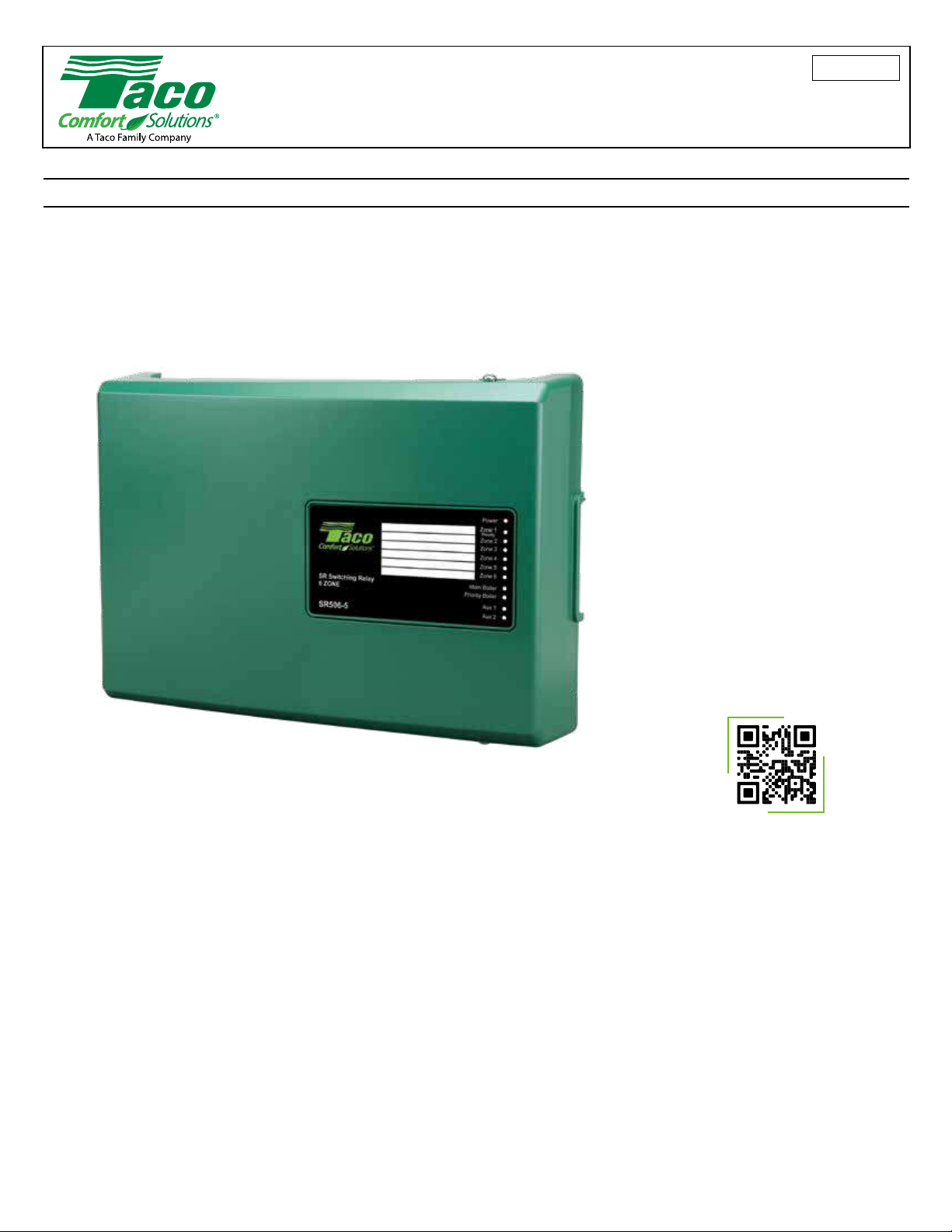
The “SR50X-5” refers to a model number where “X” represents the number of control zones. Model number “SR506-5” is used for reference
in this document. The SR506-5 is a six zone switching relay that can have up to 6 thermostats connected and will operate up to 6 zone
circulators, plus 2 auxiliary outputs (AUX) to control circulators in boiler and primary loops, for example.
The SR506-5 has a priority zone option, allowing zone 1 to operate and deactivate zones 2 through 6 during a priority call; this is ideal when
using an indirect water heater.
The SR506-5 includes timing options for
Post Purge, Pump Exercise and Priority
Protection. The SR506-R-5 also includes
an energy saving program that can
adjust the temperature of a modulatingcondensing boiler or conventional On/
Off boiler to increase the comfort level
and use less fuel, without the need to
install an outdoor sensor. It also supports
Outdoor Reset (Weather Compensation)
when outdoor sensor is connected (or
separately purchased Plug-In Reset
Control for standard SR506-5 model).
TABLE OF CONTENTS
1. Warnings & Safety Information
2. Location & Installation
3. Operation & DIP Switch Settings
4. Wiring Procedure
5. Product & Application Diagrams
6. Reset Control Setup & Wiring
For information on Taco’s Switching
Relays (SR) including catalog, instruction
sheets, submittal data sheets, and our
highly praised Zone Controls Wiring
Guide, scan the QR code below or visit
www.TacoComfort.com.
7. Troubleshooting & FAQs
8. Fuse Replacement
9. Specications
10. Accessories & Replacement Parts
11. Warranty
1
Page 2

1. WARNINGS & SAFETY INFORMATION:
FCC Regulatory Statements
This device complies with Part 15 of the FCC Rules. Operation is subject to the following two conditions:
(1) This device may not cause harmful interference.
(2) This device must accept any interference received, including interference that may cause undesired operation.
This equipment has been tested and found to comply with the limits for a Class B digital device, pursuant to part 15 of the Federal
Communication Commission (FCC) rules. These limits are designed to provide reasonable protection against harmful interference in a
residential installation. This equipment generates, uses and can radiate radio frequency energy and, if not installed and used in accordance
with the instructions, may cause harmful interference to radio communications. However, there is no guarantee that interference will not
occur in a particular installation. If this equipment causes harmful interference to radio or television reception, which can be determined by
turning the equipment off and on, the user is encouraged to try to correct the interference by doing one or more of the following measures:
• Reorient or relocate the receiving antenna.
• Increase the separation between the equipment and receiver.
• Connect the equipment into an outlet on a circuit different from that to which the receiver is connected.
• Consult the dealer or an experienced radio/TV technician for help.
NOTE: THE GRANTEE IS NOT RESPONSIBLE FOR ANY CHANGES OR MODIFICATIONS NOT EXPRESSLY APPROVED BY THE
PARTY RESPONSIBLE FOR COMPLIANCE. SUCH MODIFICATIONS COULD VOID THE USER’S AUTHORITY TO OPERATE THE
EQUIPMENT.
RF Exposure Warning
This equipment complies with FCC radiation exposure limits set forth for an uncontrolled environment. In order to avoid the possibility of
exceeding the FCC radio frequency exposure limits, human proximity to the antenna shall not be less than 20 cm during normal operation
and must not be co-located or operating in conjunction with any other antenna or transmitter.
ISED Regulatory Statements
This device complies with ISED Canada license-exempt RSS standard(s). Operation is subject to the following two conditions: (1) this
device may not cause interference, and (2) this device must accept any interference, including interference that may cause undesired
operation of the device.
Le présent appareil est conforme avec ISED Canada applicables aux appareils radio exempts de licence. L’exploitation est autorisée aux
deux conditions suivantes: (1) l’appareil ne doit pas produire de brouillage, et (2) l’utilisateur de l’appareil doit accepter tout brouillage
radioélectrique subi, même si le brouillage est susceptible d’en compromettre le fonctionnement.
CAN ICES-3 (B)/NMB-3(B)
RF Exposure Information
This equipment complies with ISED RSS-102 radiation exposure limits set forth for an uncontrolled environment. This transmitter must be
installed to provide a separation distance of at least 20 cm from all persons and must not be co-located or operating in conjunction with
any other antenna or transmitter.
Cet équipement est conforme avec ISED RSS-102 des limites d’exposition aux rayonnements dénies pour un environnement non
contrôlé. Cet émetteur doit être installé à au moins 20 cm de toute personne et ne doit pas être colocalisé ou fonctionner en association
avec une autre antenne ou émetteur.
WARNING: Wiring connections must be made in accordance with all applicable electrical codes. Use copper wire only. 120
VAC wiring must have a minimum temperature rating of 90°C. Failure to follow these instructions can result in personal injury
or death and/or property damage. 12-18 gauge wire recommended for 120 VAC connections, 14-22 gauge wire for thermostat
connections, and 14-22 gauge wire for 24 VAC source connections. All 24 VAC eld wiring terminations require
SELV/Class 2 rated wire.
WARNING: Spare fuses consist of different amp ratings (1) 1AMP and (1) 6AMP. Be sure to replace a blown fuse with the correct
fuse rating.
2
Page 3
2. LOCATION & INSTALLATION:
Planning:
Included in Package:
SR506-5 switching relay; 6 zone
Quick Start Guide
2 Spare fuses attached to inner cover
Tools & Materials Needed:
Small straight blade screwdriver
Phillips screwdriver
Torpedo level
Wire strippers
Location:
Do not mount to a surface that exceeds 104°F (40°C). For indoor use only. The unit must be located in dry interior locations. Use only
copper conductor supply wire suitable for at least 90°C. All circuits must have a common disconnect and be connected to the same
pole of the disconnect. Product is not suitable for installation in hazardous locations.
Installation:
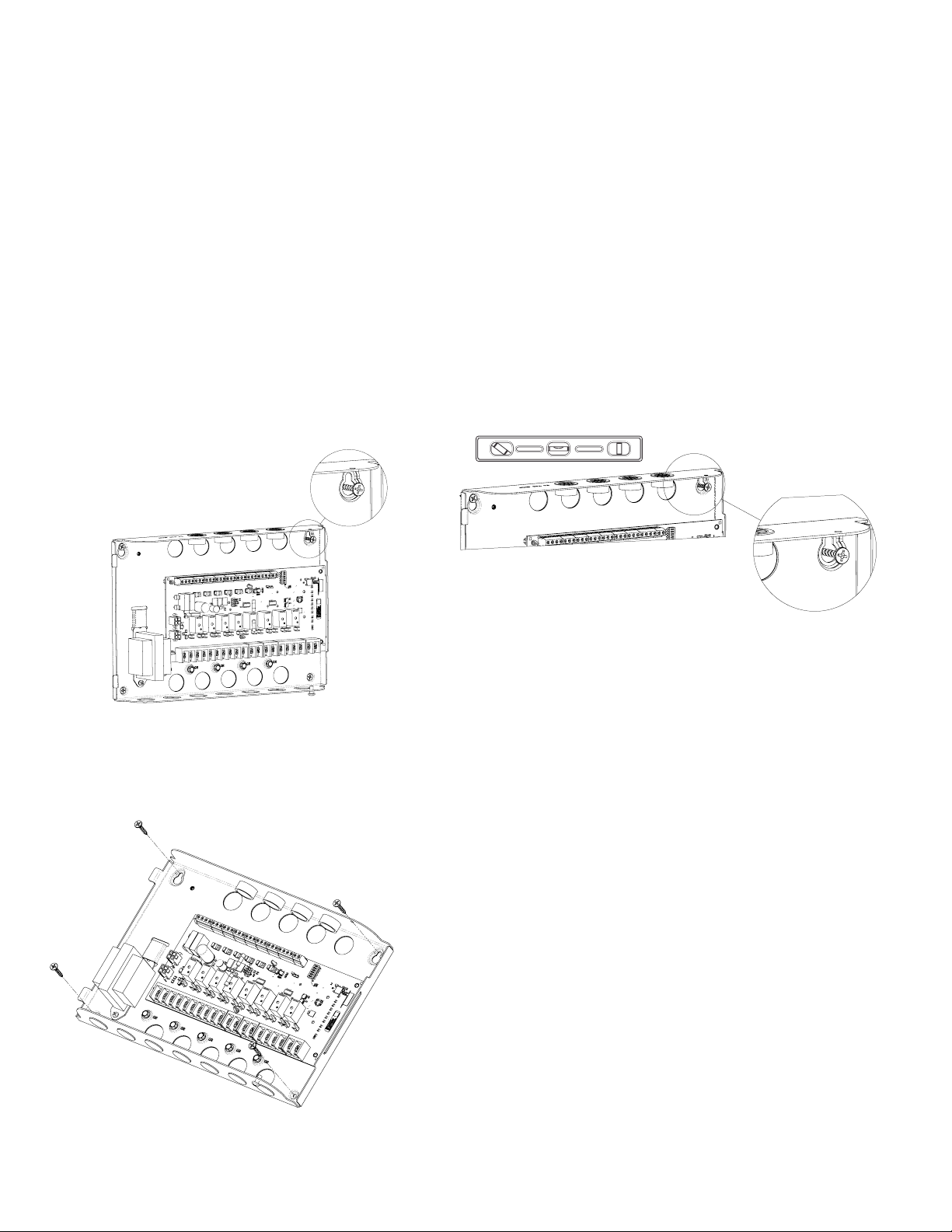
1. Hang the panel on a wall with one mounting screw. 2. Level the panel.
SR506-R-5 switching relay also includes: Strap-on temperature sensor
Screws or hardware for mounting
Electrical connectors for eld wiring
Low and live voltage wiring (per code)
3. Install other 3 mounting screws.
3
Page 4

3. OPERATION & DIP SWITCH SETTINGS:
General Operation: When any thermostat calls for heat, the appropriate circulating pump is
energized, the red light goes on and the boiler end switch relay and AUX circulator relay(s)
are energized (subject to DIP switch settings).
Expansion Connections (Modbus): Set DIP switch (#1) to MASTER on the switching relay
that is designated as the priority zone control. Set all other daisy chained zone controls to
EXPANSION. Using thermostat wire (18-22 gauge) connect between terminals A, B, GND
on the master control to the corresponding A, B, GND on the expansion zone control(s).
Zone controls may be daisy chained up to 20 Taco zoning panels using any combination of
SR and ZVC controls (120 zones if all are 6 zone panels).
Modbus is an open protocol method used for transmitting information back and forth over serial lines between Zone Control equipment.
This will allow for future expansion to the zone control portfolio and with other participating OEM’s equipment.
Priority Operation: When the priority DIP switch (#2) is set to ON and the priority zone (zone 1) is actuated, all other zones will stop
operation until priority zone is satised. When not switched to priority, all zones will operate independently. More adjustments are available
when using the Taco Control mobile app.
Priority Protection Operation: If the priority zone calls continuously for more than one hour, power is returned to all the other zones,
allowing each zone to function independently. Once the priority zone is satised, the control’s auto-reset is activated, and the priority zone
is again allowed to have priority for up to one hour starting from when it calls next.
Primary Pump Operation: When the DIP switch (#3) is set to OFF, the primary circulating pump output will energize when any zone calls
for heat, except the priority zone. When the DIP switch is set to ON, the primary circulating pump output will energize when any zone
calls for heat.
Post Purge Operation: When the DIP switch (#4) is set to ON, the last zone on will stay energized for 2 minutes after its thermostat or
aquastat is satised, but not operate the boiler. More adjustments are available when using the Taco Control mobile app. Note: Post purge
is only supported on controls designated as MASTER. Post purge is not supported on expansion controls.
Pump Exercise Operation: When the DIP switch (#5) is set to ON, the solid state timer cycles all the circulating pumps that are attached
to the Switching Relay to run for 30 seconds every 2 weeks. More adjustments are available when using the Taco Control mobile app.
When using multiple Switching Relays, only the master control DIP switch (#5) should be set to on.
Low Limit (ZC) Operation: When the DIP switch (#6) is set to ON and the boiler drops below the set low limit (terminal ZC connected
to boiler), all zone circulating pumps will stop. When the boiler rises above the set low limit, the zone circulating pumps are allowed to
operate.
AUX PUMP 1; ZR / DHW Recirc Output: The AUX PUMP 1 output is energized when any zone calls for heat. When a DHW supply
sensor is connected to Sensor Input terminals, then AUX PUMP 1 will energize a DHW recirculation pump using SmartPlus
®
logic. More
adjustments are available when using the Taco Control mobile app.
AUX PUMP 2; Primary Circulator Output: The AUX PUMP 2 output follows DIP switch setting #3 listed above. More adjustments are
available when using the Taco Control mobile app.
SmartPlus Recirc Logic: SmartPlus adds intelligence to your system by learning when hot water is used in the home. The pipe-mounted
sensor records daily hot water usage patterns during the course of the week. Recorded data is used to automatically run the circulator at
the same times the following week. So hot water is always available when it is needed. If usage pattern changes, the SmartPlus adjusts
automatically.
“Smart” Mode (default mode): The SmartPlus logic will run in Pulse mode as described below for the rst 7 days of operation. During
the rst 7 days, the SmartPlus logic monitors and records the home’s hot water usage pattern. For the following 7 days, the SmartPlus
logic will use the preceding week’s usage pattern to cycle the pump during the recorded hot water usage times. This process of
recording and repeating is continuous, and automatically adjusts the pump’s “ON” times to match the household’s usage pattern.
“Pulse” Mode: When set to Pulse mode, the SmartPlus logic will cycle the circulator pump “ON” for 5 minutes, then “OFF” for 10
minutes to maintain hot water at all faucets and taps. It will repeat the cycle continuously. More adjustments are available when using
the Taco Control mobile app.
When a DHW supply sensor is connected to the Sensor Input terminals, AUX PUMP 1 output will now be designated for recirculation of
DHW loop and activated in “Smart” mode based on DHW usage.
4
Page 5
4. WIRING PROCEDURE:
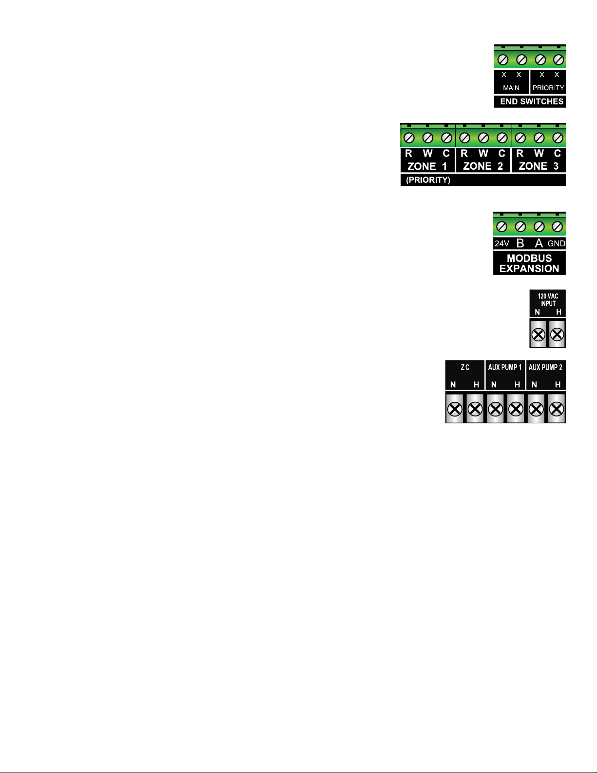
End Switches (Low Voltage Dry Contacts):
Main - The main end switch closes when any zone thermostat calls for heat and connects to T-T on boiler operating
control.
Priority - The priority end switch closes only when the priority zone thermostat or aquastat is calling for heat and
connects to DHW T-T on boiler (optional).
Thermostat Input (24 VAC):
R Hot side of transformer. Connect to R on thermostat.
W Switched R signal from thermostat. Connect to W on thermostat.
C Common side of transformer. Connect to COM on thermostat (optional).
Note: Some “Power Stealing” style thermostats may require a resistor between the
W & C terminals; a 1000 Ohms 1/2 watt (or larger) have proved to work.
Expansion Connections (24 VAC):
A Connect A on Master zone control to A on all Expansion zone control(s).
B Connect B on Master zone control to B on all Expansion zone control(s).
G Connect GND on Master zone control to GND on all Expansion zone control(s).
24V Future use; no connection required.
Power Input (120 VAC):
H Connect to 120 VAC Hot side of power supply to zone control.
N Connect to 120 VAC Neutral side of power supply to zone control.
G Connect ground wire to ground screws on base of zone control.
Low Limit Aquastat / Tankless Coil Application (120 VAC):
ZR - H Connect the Hot (AUX PUMP 1) output to ZR input on boiler’s operating control.
ZR - N Neutral (optional).
ZC - H Connect the ZC (Hot) input to ZC (Hot) output on boiler’s operating control.
ZC - N Connect (optional).
AUX PUMP 1; ZR /DHW Recirc Output (120 VAC):
H Connect the Hot output to Hot power input on circulator.
N Connect the Neutral output to Neutral power input on circulator.
G Connect ground wire to ground screws on base of zone control.
AUX PUMP 2; Primary Circulator Output (120 VAC):
H Connect the Hot output to Hot power input on circulator.
N Connect the Neutral output to Neutral power input on circulator.
G Connect ground wire to ground screws on base of zone control.
5
Page 6
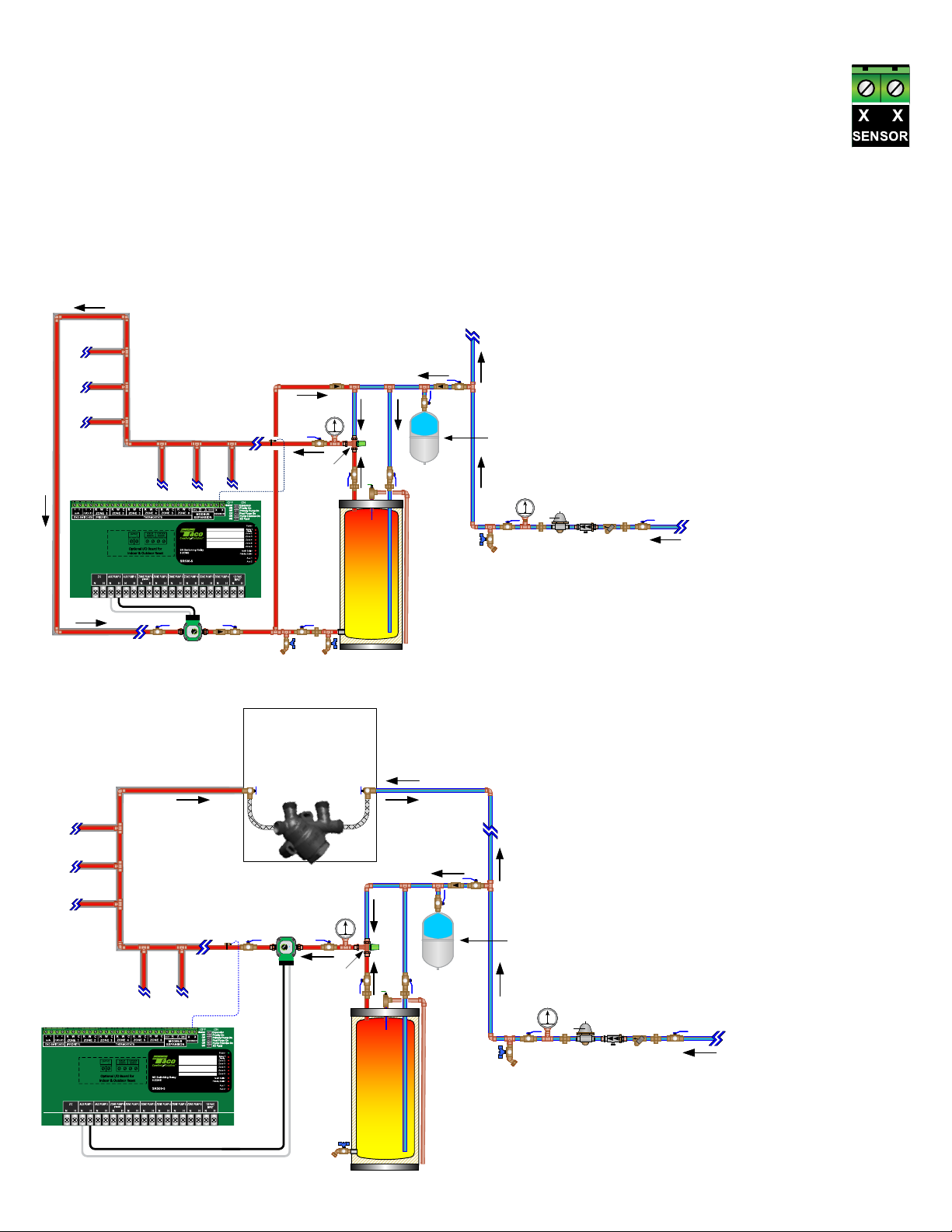
DHW Recirculation using SmartPlus Logic
SmartPlus Recirc Logic Sensor
• Mount the strap-on sensor on domestic hot water supply pipe on water heater using wire tie or pipe clamp and insulate
sensor with pipe insulation.
• The sensor must be strapped to metal piping. A short piece of copper or brass tube should be added into non metallic
systems for sensor attachment. For best performance, the strap on sensor should be installed a minimum of 6 feet away
from the DHW output but before the rst xture.
• Connect the strap-on sensor to the two terminals labeled Sensor Input Terminal on switching relay.
SmartPlus Recirc Pump Power
• Wire Hot and Neutral from Recirc Pump to Hot and Neutral of AUX PUMP 1 output.
Dedicated Return Line Piping Diagram
Dedicated
Dedicated
Return Line
Return Line
Cold Water
Cold Water
out to
out to
Fixtures
Fixtures
Check
Check
Valve
Valve
Potable Exp. Tank
Potable Exp. Tank
(valve if permitted by local code)
(valve if permitted by local code)
Pressure
Pressure
Isolation
Isolation
Isolation
Valve
Valve
Valve
Hose
Hose
Hose
Bibb
Bibb
Bibb
Gauge
Gauge
P GP G
P G
P G
Union
Union
P.R.V.
P.R.V.
B.F.P.
B.F.P.
Strainer
Strainer
Union
Union
Isolation
Isolation
Valve
Valve
Incoming
Incoming
Cold Water
Cold Water
Switching Relay with
SmartPlus Logic
Kitchen
Kitchen
Laundry
Laundry
Lav
Lav
Tub Shower
Tub Shower
Lav
Lav
DIP SWITCH SETTINGS
Temp
Temp
Sensor
Sensor
ASSE 1070 /
1017 Dual
Listed Mixing
Valve
NSF 61 w/
Integral checks
& Temp Gauge
12" Thermal
Trap
Recommended
T GT G
T G
Water
Water
Heater
Heater
Dedicated
Dedicated
Return Line
Return Line
Hot-Link
®
Switching Relay with SmartPlus Logic
Isolation Valves, Unions and
Isolation Valves, Unions and
Hose Bibbs as depicted
Hose Bibbs as depicted
Valve or Crossover Style Valve Piping Diagram
Kitchen
Laundry
Lav
Tub Shower
Temp
Sensor
DIP SWITCH SETTINGS
Hot-Link bypass
valve w/ check
Farthest Sink/Lav away on
this particular branch system,
multiple valves may be
required
T GT G
ASSE 1070 /
1017 Dual
Listed Mixing
Valve
NSF 61 w/
Integral checks
& Temp Gauge
12" Thermal
Trap
Recommended
Water
Heater
Check
Valve
Cold Water
out to
Fixtures
Potable Exp. Tank
(valve if permitted by local code)
Pressure
Pressure
Gauge
Gauge
Isolation
Isolation
Isolation
Valve
Valve
Valve
Hose
Hose
Hose
Bibb
Bibb
Bibb
P GP G
P G
P G
Union
Union
P.R.V.
P.R.V.
B.F.P.
B.F.P.
Strainer
Strainer
Union
Union
Isolation
Isolation
Valve
Valve
Incoming
Incoming
Cold Water
Cold Water
Conceptual Sketches Only, refer to individual manufacturer’s installation instructions for additional details. Local codes shall prevail.
6
Page 7
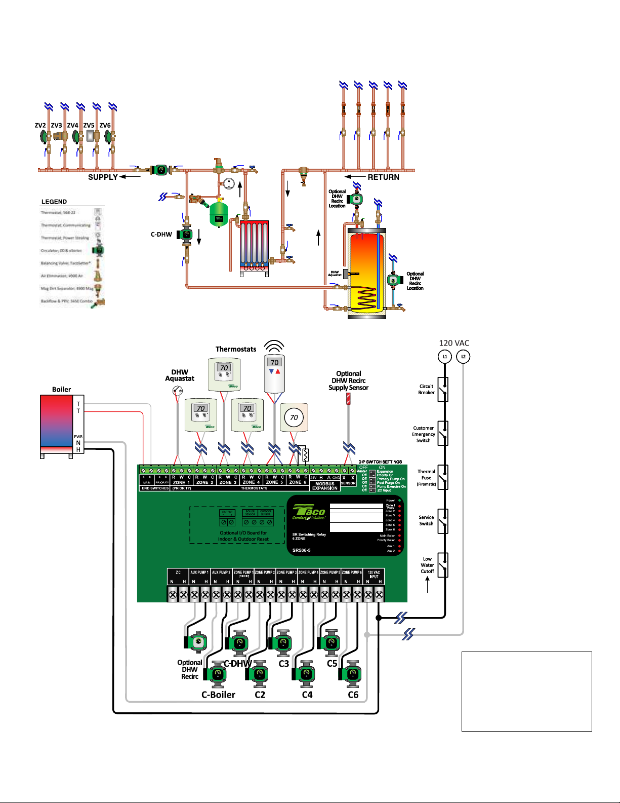
5. PRODUCT & APPLICATIONS DIAGRAMS:
PA01C – SR506-5 with 5 Zone Circulators & Indirect DHW; Supply & Return Headers
Mechanical Diagram
C-ZV
P GP G
Electrical Diagram
HEAT
See
Note 1
See
Note 2
DIP Switch Settings
1. OFF - Master
2. ON - Priority
3. OFF - Primary Pump
4. OFF or ON - Post Purge
5. OFF or ON - Pump Exercise
6. OFF – ZC Low Limit
Note 1: Some “Power Stealing” style thermostats may require a resistor between the W & C terminals; a 1000 Ohms 1/2 watt (or larger) have proved to work.
Note 2: Ensure load of zone control, circulator(s) & boiler do not exceed LWCO rating.
Conceptual Sketches Only, refer to individual manufacturer’s installation instructions for additional details. Local codes shall prevail.
7
Page 8
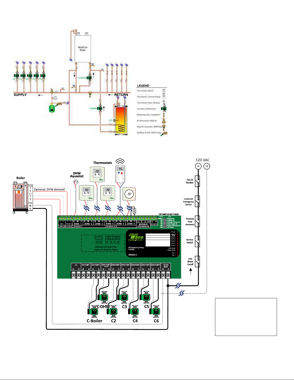
PA02C - SR506-5 with 5 Zone Circulators & Indirect DHW; Primary/Secondary
>ϭ >Ϯ
ŝƌĐƵŝƚ
ƌĞĂŬĞƌ
&ƵƐĞ
^ĞƌǀŝĐĞ
^ǁŝƚĐŚ
>Žǁ
tĂƚĞƌ
ƵƚŽĨĨ
ϭϮϬǀĂĐ
>ϭ >Ϯ
ŝƌĐƵŝƚ
&ƵƐĞ
^ĞƌǀŝĐĞ
^ǁŝƚĐŚ
>Žǁ
tĂƚĞƌ
ƵƚŽĨĨ
ϭϮϬǀĂĐ
>ϭ >Ϯ
ŝƌĐƵŝƚ
&ƵƐĞ
^ĞƌǀŝĐĞ
^ǁŝƚĐŚ
>Žǁ
tĂƚĞƌ
ƵƚŽĨĨ
ϭϮϬǀĂĐ
EŽƚĞϮ
EŽƚĞϮ
Mechanical Diagram
See
Note 3
Electrical Diagram
See Note 3
See
Note 1
See
^ĞĞ
^ĞĞ
Note 2
DIP Switch Settings
1. OFF - Master
2. ON - Priority
3. OFF - Primary Pump
4. OFF or ON - Post Purge
5. OFF or ON - Pump Exercise
6. OFF – ZC Low Limit
Note 1: Some “Power Stealing” style thermostats may require a resistor between the W & C terminals; a 1000 Ohms 1/2 watt (or larger) have proved to work.
Note 2: Ensure load of zone control, circulator(s) & boiler do not exceed LWCO rating.
Note 3: Follow boiler manufacturer’s recommendations on powering of boiler loop circulator. Some boilers require this circulator to be wired to the boiler operating control.
Conceptual Sketches Only, refer to individual manufacturer’s installation instructions for additional details. Local codes shall prevail.
8
Page 9
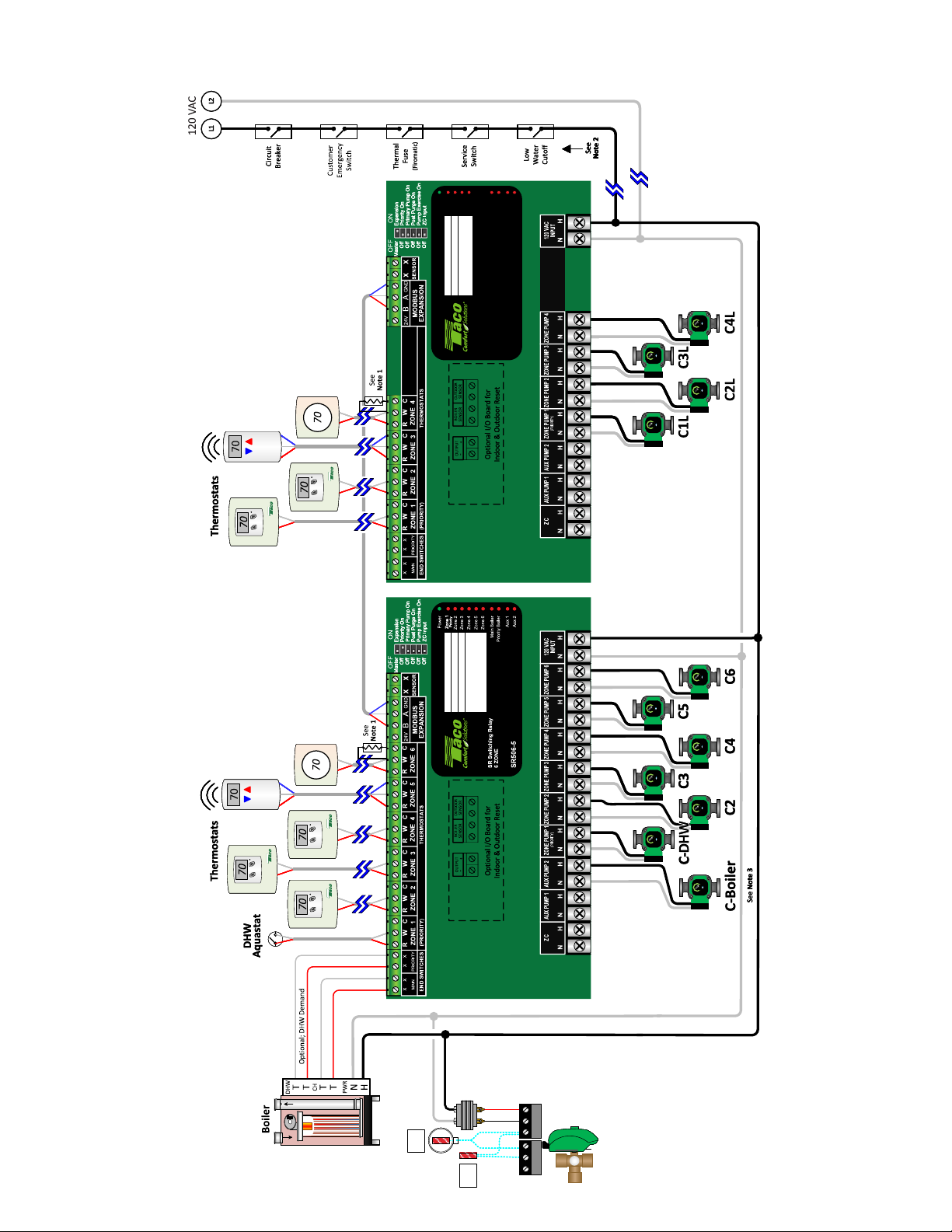
PA03C – High & Low Temperature Zones & Indirect DHW; Primary/Secondary
Electrical Diagram
Aux 1
Zone 4
Aux 2
Main Boiler
Priority Boiler
SR Switching Relay
4 ZONE
SR504-5
DIP Switch Settings - Expansion
1. ON - Expansion
2. OFF - Priority
3. OFF - Primary Pump
4. OFF or ON - Post Purge
5. OFF or ON - Pump Exercise
6. OFF – ZC Low Limit
Priority
Power
Zone 1
Zone 2
Zone 3
DIP SWITCH SETTINGS
DIP Switch Settings - Master
1. OFF - Master
2. ON - Priority
3. OFF - Primary Pump
4. OFF or ON - Post Purge
5. OFF or ON - Pump Exercise
6. OFF – ZC Low Limit
DIP SWITCH SETTINGS
R
R
R
R
R
C
C
C
C
C
COMRCOM
COM
COM
COM
Sensor
Outdoor
Supply
Sensor
COM
Conceptual Sketches Only, refer to individual manufacturer’s installation instructions for additional details. Local codes shall prevail.
Note 1: Some “Power Stealing” style thermostats may require a resistor between the W & C terminals; a 1000 Ohms 1/2 watt (or larger) have proved to work.
Note 2: Ensure load of zone control, circulator(s) & boiler do not exceed LWCO rating.
Note 3: Follow boiler manufacturer’s recommendations on powering of boiler loop circulator. Some boilers require this circulator to be wired to the boiler operating control.
BOL SUP OUTBOL SUP OUT
BOL SUP OUT
BOL SUP OUT
BOL SUP OUT
BOL SUP OUT
9
Page 10
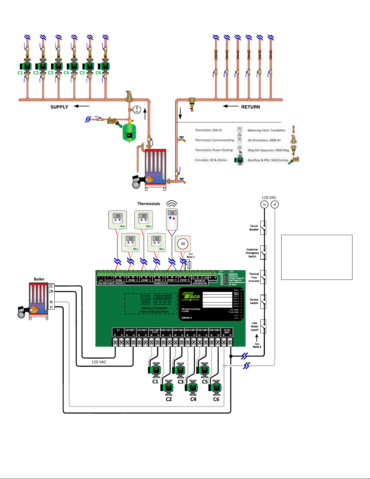
PA04C – Boiler with Tankless Coil; Supply & Return Headers
Mechanical Diagram
P GP G
Electrical Diagram
LEGEND
DIP SWITCH SETTINGSDIP SWITCH SETTINGSDIP SWITCH SETTINGSDIP SWITCH SETTINGSDIP SWITCH SETTINGS
DIP Switch Settings
1. OFF - Master
2. OFF - Priority
3. OFF - Primary Pump
4. OFF or ON - Post Purge
5. OFF or ON - Pump Exercise
6. ON – ZC Low Limit
SAFETY NOTICE - TWO SEPARATE sources of power may be connected to an oil boiler’s aquastat control.
Before servicing an oil red boiler, make sure the service switch is off. Then conrm that a secondary source of power does not exist to the boiler’s
aquastat control. Failure to x the problem could result in boiler being activated when zone calls for heat, that could result in serious injury or death.
Note 1: Some “Power Stealing” style thermostats may require a resistor between the W & C terminals; a 1000 Ohms 1/2 watt (or larger) have proved to work.
Note 2: Ensure load of zone control, circulator(s) & boiler do not exceed LWCO rating.
Conceptual Sketches Only, refer to individual manufacturer’s installation instructions for additional details. Local codes shall prevail.
10
Page 11
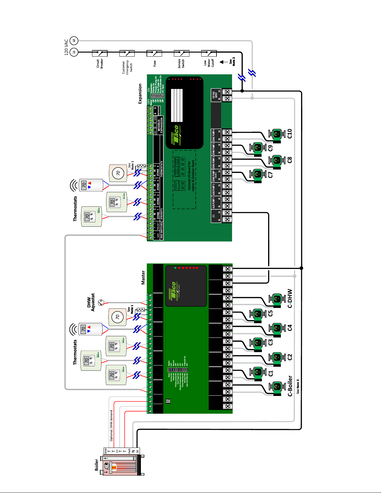
PA05C – Legacy Zone Controls – SR506-EXP-4 (Master) Connected to SR504-5 (Expansion)
Electrical Diagram
Aux 1
Priority
Power
Zone 1
Zone 2
Zone 3
Zone 4
DIP SWITCH SETTINGS
Aux 2
Main Boiler
Priority Boiler
SR Switching Relay
4 ZONE
SR504-5
120
Power
Power
Power
Zone 1
Zone 2
Zone 3
Zone 4
Zone 5
Zone 1
Zone 2
Zone 3
Zone 4
Zone 5
Zone 1
Zone 2
Zone 3
Zone 4
Zone 5
RELAY
RELAY
RELAY
6 ZONE
6 ZONE
6 ZONE
SWITCHING
SWITCHING
SWITCHING
SR506-4
SR506-4
R W C
R W C
(PRIORITY)
(PRIORITY)
T STAT 4 T STAT 5T STAT 6
T STAT 4 T STAT 5T STAT 6
T STAT 2 T STAT 3
T STAT 2 T STAT 3
R W C R W C R W C R W C R W C
R W C R W C R W C R W C R W C
T STAT 1
T STAT 1
A B C
EXPANSION
END
END
BOILER
BOILER
SWITCH
SWITCH
PRIORITY
PRIORITY
END
END
MAIN
MAIN
SWITCH
SWITCH
BOILER
BOILER
SR506-4
DIP SWITCH
Power
Controls
VAC
Zone 6
Zone 6
Zone 6
(PRIORITY)
120 VAC
N/C
N H
N H
POWER IN
POWER IN
N H
N H
ZONE 6
N H
N H
ZONE 6
ZONE 6
N H
N H
ZONE 5
ZONE 5
N H
N H
ZONE 4
ZONE 4
ZONE 3
ZONE 3
N H N H
N H N H
ZONE 2
ZONE 2
N H
N H
ZONE 1
ZONE 1
N H
N H
PRIMARY
PRIMARY
120
120
VAC
VAC
ZC ZR
ZC ZR
Note 1: Some “Power Stealing” style thermostats may require a resistor between the W & C terminals; a 1000 Ohms 1/2 watt (or larger) have proved to work.
Note 2: Ensure load of zone control, circulator(s) & boiler do not exceed LWCO rating.
Note 3: Follow boiler manufacturer’s recommendations on powering of boiler loop circulator. Some boilers require this circulator to be wired to the boiler operating control.
Conceptual Sketches Only, refer to individual manufacturer’s installation instructions for additional details. Local codes shall prevail.
11
Page 12
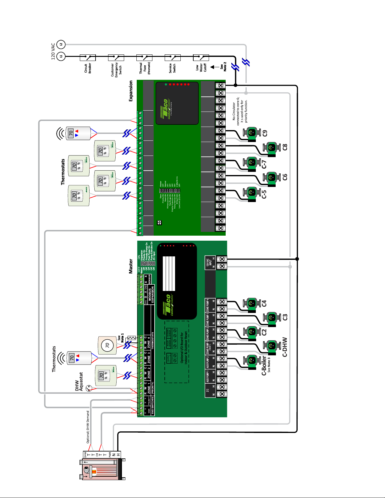
PA06C – Legacy Zone Controls – SR504-5 (Master) Connected to SR506-EXP-4 (Expansion)
Electrical Diagram
VAC
120
120
120
VAC
VAC
(PRIORITY)
(PRIORITY)
(PRIORITY)
120
N/C
N/C
N/C
VAC
N H
N H
N H
N H
POWER IN
POWER IN
POWER IN
POWER IN
N H
N H
N H
N H
ZONE 6
ZONE 6
ZONE 6
N H
N H
N H
N H
ZONE 6
ZONE 6
ZONE 6
ZONE 6
N H
N H
N H
N H
ZONE 5
ZONE 5
ZONE 5
ZONE 5
N H
N H
N H
N H
ZONE 4
ZONE 4
ZONE 4
ZONE 4
ZONE 3
ZONE 3
ZONE 3
ZONE 3
N H N H
N H N H
N H N H
N H N H
ZONE 2
ZONE 2
ZONE 2
ZONE 2
N H
N H
N H
N H
ZONE 1
ZONE 1
ZONE 1
ZONE 1
’
Power
Power
Power
Zone 1
Zone 2
Zone 3
Zone 4
Zone 5
Zone 6
Zone 1
Zone 2
Zone 3
Zone 4
Zone 5
Zone 6
Zone 1
Zone 2
Zone 3
Zone 4
Zone 5
Power
Power
R W C
R W C
R W C
R W C
(PRIORITY)
(PRIORITY)
(PRIORITY)
(PRIORITY)
T STAT 4 T STAT 5T STAT 6
T STAT 4 T STAT 5T STAT 6
T STAT 4 T STAT 5T STAT 6
T STAT 4 T STAT 5T STAT 6
T STAT 2 T STAT 3
T STAT 2 T STAT 3
T STAT 2 T STAT 3
T STAT 2 T STAT 3
R W C R W C R W C R W C R W C
R W C R W C R W C R W C R W C
R W C R W C R W C R W C R W C
R W C R W C R W C R W C R W C
T STAT 1
T STAT 1
T STAT 1
T STAT 1
Zone 6
Zone 1
Zone 2
Zone 3
Zone 4
Zone 5
Zone 6
Zone 1
Zone 2
Zone 3
Zone 4
Zone 5
Zone 6
RELAY
RELAY
RELAY
6 ZONE
6 ZONE
6 ZONE
RELAY
RELAY
6 ZONE
6 ZONE
SWITCHING
SWITCHING
SWITCHING
SWITCHING
SWITCHING
SR506-4
SR506-4
SR506-4
SR506-4
SR506-4
DIP SWITCH
DIP SWITCH
DIP SWITCH
A B C
A B C
A B C
EXPANSION
EXPANSION
EXPANSION
END
END
END
END
BOILER
BOILER
BOILER
BOILER
SWITCH
SWITCH
SWITCH
SWITCH
PRIORITY
PRIORITY
PRIORITY
PRIORITY
MAIN
MAIN
MAIN
MAIN
DIP SWITCH SETTINGSDIP SWITCH SETTINGSDIP SWITCH SETTINGSDIP SWITCH SETTINGS
Power
Power
Power
Power
Controls
Controls
Controls
Controls
END
END
END
END
SWITCH
SWITCH
SWITCH
SWITCH
BOILER
BOILER
BOILER
BOILER
Aux 1
Power
Zone 1
Priority
Zone 2
Zone 3
Zone 4
Aux 2
Main Boiler
Priority Boiler
SR Switching Relay
4 ZONE
SR504-5
N H
N H
N H
N H
PRIMARY
PRIMARY
PRIMARY
PRIMARY
120
120
120
120
VAC
VAC
VAC
VAC
ZC ZR
ZC ZR
ZC ZR
ZC ZR
12
Note 1: Some “Power Stealing” style thermostats may require a resistor between the W & C terminals; a 1000 Ohms 1/2 watt (or larger) have proved to work.
Note 2: Ensure load of zone control, circulator(s) & boiler do not exceed LWCO rating.
Note 3: Follow boiler manufacturer’s recommendations on powering of boiler loop circulator. Some boilers require this circulator to be wired to the boiler operating control.
Conceptual Sketches Only, refer to individual manufacturer’s installation instructions for additional details. Local codes shall prevail.
Page 13
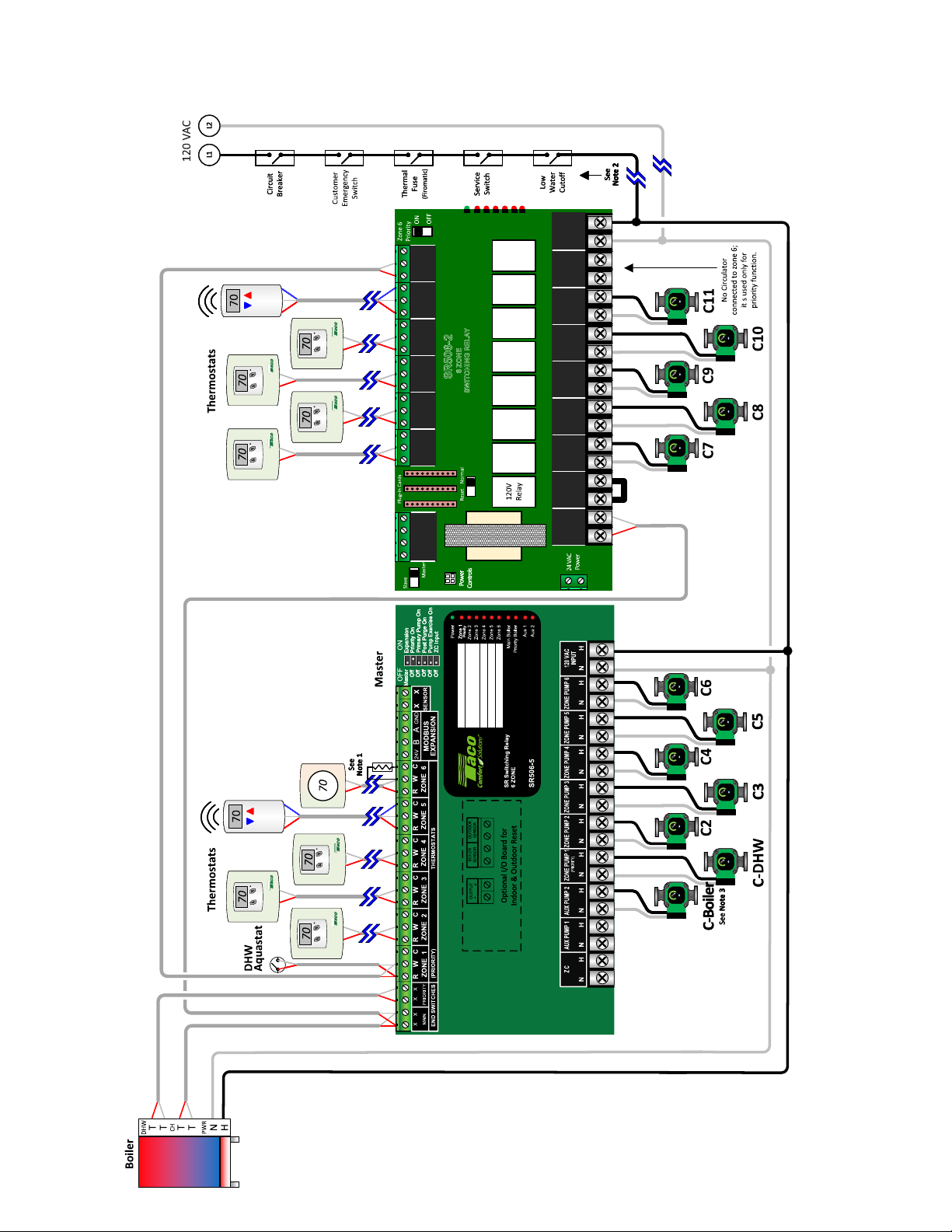
PA07C – Legacy Zone Controls – SR504-5 (Master) Connected to SR506-EXP-2 (Expansion)
Electrical Diagram
R W C
R W C
R W C R W C R W C R W C R W C
R W C R W C R W C R W C R W C
1 2 3 4
1 2 3 4
Expansion
Power
Zone 1
Zone 2
Zone 3
Zone 4
(PRIORITY)
T STAT 4 T STAT 5T STAT 6
T STAT 4 T STAT 5T STAT 6
6 ZONE
SR506-2
WITCHING RELAY
S
T STAT 2 T STAT 3
T STAT 2 T STAT 3
T STAT 1
T STAT 1
EXPANSION
EXPANSION
VAC
Zone 5
Zone 6
N H
120
POWER IN
N H
(PRIORITY)
’
N H
ZONE 5 ZONE 6
N H
ZONE 4
ZONE 3
N H N H
ZONE 2
N H
ZONE 1
120
VAC
ZC ZR
End
X X
Switch
DIP SWITCH SETTINGS
Note 1: Some “Power Stealing” style thermostats may require a resistor between the W & C terminals; a 1000 Ohms 1/2 watt (or larger) have proved to work.
Note 2: Ensure load of zone control, circulator(s) & boiler do not exceed LWCO rating.
Note 3: Follow boiler manufacturer’s recommendations on powering of boiler loop circulator. Some boilers require this circulator to be wired to the boiler operating control.
Conceptual Sketches Only, refer to individual manufacturer’s installation instructions for additional details. Local codes shall prevail.
13
Page 14
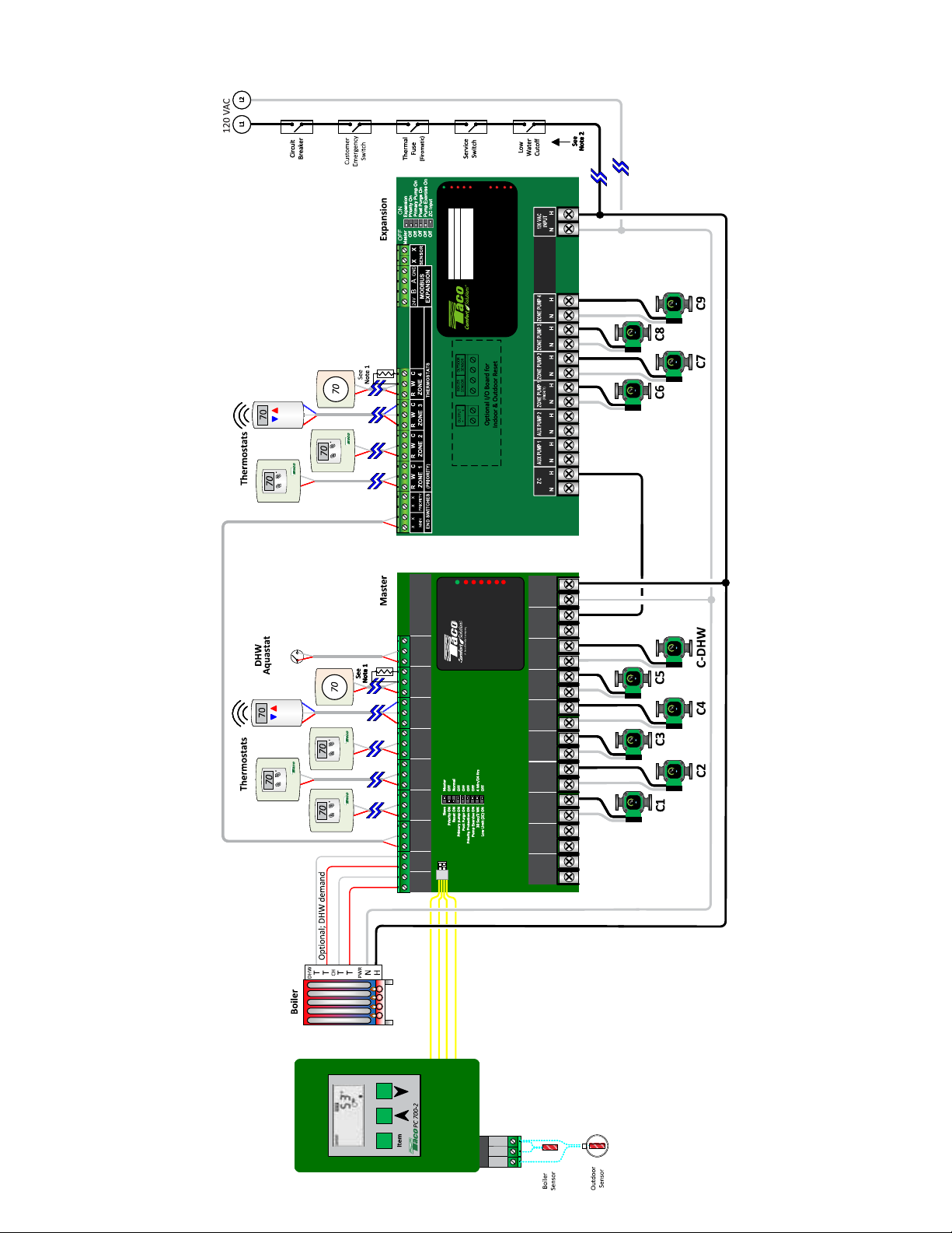
PA07C – Legacy Zone Controls – SR506-EXP-4 (Master) with PC700-2 Boiler Reset Control Connected to SR504-5 (Expansion)
Electrical Diagram
Aux 1
Zone 4
Aux 2
Main Boiler
Priority Boiler
SR Switching Relay
4 ZONE
SR504-5
Priority
Power
Zone 1
Zone 2
Zone 3
DIP SWITCH SETTINGSDIP SWITCH SETTINGSDIP SWITCH SETTINGSDIP SWITCH SETTINGS
120
120
VAC
Power
Power
Power
Zone 1
Zone 2
Zone 3
Zone 4
Zone 1
Zone 2
Zone 3
Zone 4
Zone 5
Zone 1
Zone 2
Zone 3
Zone 4
Zone 5
6 ZONE
6 ZONE
6 ZONE
SWITCHING
SWITCHING
SWITCHING
SR506-4
SR506-4
R W C
R W C
(PRIORITY)
(PRIORITY)
T STAT 4T STAT 5T STAT 6
T STAT 4T STAT 5T STAT 6
T STAT 2T STAT 3
T STAT 2T STAT 3
R W C R W C R W C R W C R W C
R W C R W C R W C R W C R W C
T STAT 1
T STAT 1
A B C
EXPANSION
END
END
BOILER
BOILER
SWITCH
SWITCH
PRIORITY
PRIORITY
END
END
MAIN
MAIN
SWITCH
SWITCH
BOILER
BOILER
SR506-4
DIP SWITCH
Power
Controls
VAC
Zone 5
Zone 6
Zone 6
Zone 6
RELAY
RELAY
RELAY
N H
N H
POWER IN
POWER IN
N/C
N H
N H
ZONE 6
N H
N H
ZONE 6
ZONE 6
(PRIORITY)
N H
N H
ZONE 5
ZONE 5
N H
N H
ZONE 4
ZONE 4
ZONE 3
ZONE 3
N H N H
N H N H
ZONE 2
ZONE 2
N H
N H
ZONE 1
ZONE 1
N H
N H
PRIMARY
PRIMARY
120
120
VAC
VAC
ZC ZR
ZC ZR
14
m
m
m
3
3
3
Co
Co
Co
t
t
t
Ou
Ou
Ou
power
No
No
power
power
l
l
l
1 2
1 2
1 2
No
Boi
Boi
Boi
Note 1: Some “Power Stealing” style thermostats may require a resistor between the W & C terminals; a 1000 Ohms 1/2 watt (or larger) have proved to work.
Note 2: Ensure load of zone control, circulator(s) & boiler do not exceed LWCO rating.
Conceptual Sketches Only, refer to individual manufacturer’s installation instructions for additional details. Local codes shall prevail.
Page 15
6. RESET CONTROL SETUP & WIRING (OPTIONAL)
Boiler Reset Types: The SR506-R-5 includes two types of boiler reset control logic: (or separately purchased Plug-In Reset Control
for standard SR506-5 model)
Indoor Reset Control (Load Reset) uses the thermostat cycling information to determine the supply water temperature. Thermostat
short cycling often suggests that the supply water temperature is too high, while prolonged cycles typically indicate that the water
temperature is too low.
Outdoor Reset Control (Weather Compensation) uses an outdoor sensor to compare it against the reset ratio (congured by installer)
to determine the appropriate supply water temperature. Outdoor sensor must be purchased separtately.
General Operation: When any thermostat calls for heat, the appropriate circulator is energized, and the red light goes on. The boiler
end switch relay and modulating output will be controlled by the reset algorithm; or, either based on indoor thermostat operation or
on outdoor temperature.
Control Setup: The Taco Control mobile app is required to set type of reset control and parameters to operate.
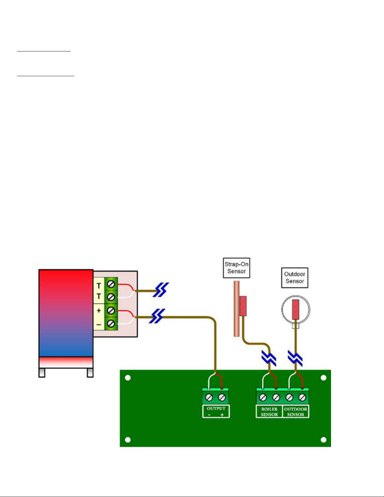
Wiring of Reset Control:
Make all sensor and analog output connections to the small Plug-In Reset Control on SR506-R-5.
Sensor Connections:
Boiler Sensor: A boiler supply sensor is required for either indoor or outdoor reset. Mount the provided strap-on sensor
to the supply piping of the boiler, and wire it to the Boiler Sensor terminal block on the zone control.
Outdoor Sensor: An outdoor sensor is required when utilizing the outdoor reset function. Mount the Taco outdoor sensor
P# 9300-2052RP on north side of building and wire to Outdoor Sensor terminal block on zone control.
Boiler Connections:
Modulating Output: Most Mod-Con boilers have an input for an external modulating signal (0-10 vdc or 4-20 ma) to control
boiler. Connect the modulating output to appropriate input terminals on boiler; noting that the polarity is
correct. Some Mod-Con boilers also require a T T call for heat to activate boiler. In this case, wire the
Main Boiler End Switch to T T input on boiler.
Dry Contact End Switch: ON/OFF boilers are controlled by the Main Boiler End Switch on zone control. Wire the Main Boiler End
Switch to T T input on boiler.
15
Page 16
7. TROUBLE SHOOTING & FAQs
Problem: Digital thermostats do not work correctly when connected to a switching relay.
Solution: Some thermostats are a “Power Stealing” type which means they are powered by the switching relay with just 2 wires
(R & W). A resistor may be needed in order to have the thermostat work properly. This resistor should be placed between the
W & C (common) terminals of the switching relay. If the thermostat manufacturer does not supply a resistor, a 1000 ohm ½ watt
resistor has proven to work with most.
Problem: No heat in a zone or room of building.
Solution: LED diagnostic lights will help nd a component that is not working properly. The green LED should always be on, indicating
that power is connected, and the solid-state fuse is good. When there is a call for heat, the red LED will come on indicating power to
the zone circulator. This indicates the thermostat is working correctly. If the red LED does not come on, then check the thermostat and
thermostat wiring for errors.
Trouble Shooting Sensors:
As in any troubleshooting procedure, it is important to isolate a problem as much as possible before proceeding. The blinking error LED
light greatly simplies troubleshooting of the SR50X-R-5. If you suspect a wiring fault, return to section 4 and carefully check all external
wiring and wiring connections.
Sensor Errors:
• If an outdoor sensor fault occurs, the SR50X-R-5 will assume a xed outdoor temperature of 32°F (0°C) and will target the
appropriate supply water temperature. The Main Boiler light will blink indicating the outdoor sensor error.
• If a boiler sensor fault occurs, the SR50X-R-5 turns the boiler output off and the Priority Boiler light will blink indicating the boiler
supply sensor error.
Testing the Sensors:
Sensor Error Handling
Sensor Shorted Sensor Open Sensor
Boiler Sensor Flash once Main Boiler LED Flash twice Main Boiler LED
Outdoor Sensor Flash once Priority Boiler LED Flash twice Priority Boiler LED
Universal Sensor (Recirc) Flash once AUX PUMP 1 LED Flash twice AUX PUMP 1 LED
A good quality test meter capable of measuring up to 5,000 kΩ (1 k = 1000 Ω) is required to measure the sensor resistance. In addition
to this, the actual temperature must be measured with either a good quality digital thermometer, or, if a thermometer is not available,
a second sensor can be placed alongside the one to be tested and the readings compared. First, measure the temperature using
the thermometer and then measure the resistance of the sensor at the control. The wires from the sensor must not be connected to
the control while the test is performed. Using the chart below, estimate the temperature measured by the sensor. The sensor and
thermometer readings should be close. If the test meter reads a very high resistance, there may be a broken wire, a poor wiring
connection or a defective sensor. If the resistance is very low, the wiring may be shorted, there may be moisture in the sensor, or the
sensor may be defective. To test for a defective sensor, measure the resistance directly at the sensor location.
Temperature Resistance
ºF ºC Ω
-30 -34 234,196
-20 -29 165,180
-10 -23 118,018
0 -18 85,362
10 -12 62,465
20 -7 46,218
Temperature Resistance
ºF ºC Ω
30 -1 34,558
40 4 26,099
50 10 19,900
60 16 15,311
70 21 11,883
80 27 9,299
Temperature Resistance
ºF ºC Ω
90 32 7,334
100 38 5,828
110 43 4,665
120 49 3,760
130 54 3,050
140 60 2,490
Temperature Resistance
ºF ºC Ω
150 66 2,045
160 71 1,689
170 77 1,403
180 82 1,172
190 88 983
200 93 829
8. FUSE REPLACEMENT:
Fuses are replaceable; 2 spare fuses are attached to inside of front cover.
WARNING: Spare fuses consist of different amp ratings (1) 1AMP and (1) 6AMP. Be sure to replace a blown fuse with the correct
fuse rating.
16
Page 17

9. SPECIFICATIONS:
Power and Electrical Ratings:
Power Supply: 120 VAC ±10%, 60Hz, 20A
Zone Pump Output Rating: 120 VAC, 1/6 HP
AUX(s) Pump Output Rating:
120 VAC, 1/6 HP
Boiler End Switch Contact Rating:
24 VAC, 1A
Expansion Terminals: Low voltage, 3-wire
polarity-sensitive, digital communications that
links other Switching Relays (SR-5), Zone Valve
Controls (ZVC-5) and other Modbus equipment.
Electrical Terminals (Line Voltage):
Wire Range: 12–18AWG
Torque Screws: 7.0 lbs-in. Max.
Electrical Terminals (Low Voltage):
Wire Range: 14–22AWG
Torque Screws: 3.5 lbs-in. Max.
Transformer Rating:
20 VA, 24 VAC Class II
40 VA with option of second 20 VA transformer
ZC Input Rating:
120 VAC
Environmental Ratings:
Ambient Temperature Rating:
32°F to 104°F (0°C to 40°C)
Operating Humidity Range (% RH):
5 to 90% RH, noncondensing
Sensor Temperature Rating:
-58°F to 230°F (-50°C to 110°C)
DIP Switch Timing Settings:
Post Purge: 30 seconds; adjustable with Taco Control
mobile app
Pump Exercise: 30 seconds per 2 weeks of space
heating inactivity; adjustable with Taco Control mobile
app
Thermostat Compatibility: Compatible with most
mechanical, battery operated, power-stealing (powerrobbing), hardwired and “Smart” thermostats.
Temperature Sensor: 10K ohm NTC thermistor at
77°F (25°C) ± 0.5°F (±0.3°C), beta=3892. Lead length:
up to 500 ft. (150 m) using 18 AWG or larger wire.
Dimensions (HxWxD): 12.58 x 8.44 x 2.66 in.
(31.95 x 21.44 x 6.76 cm) approximate
Weight: 4.83 lb. (2.19 kg)
Approvals: UL, FCC
Boiler Modulating Output Rating:
0-10 VDC Mode; 500 Ω min impedance
4-20 mA Mode; 1k Ω max impedance
(With Plug-In Reset Control)
10. ACCESSORIES & REPLACEMENT PARTS
Item Part Number
Strap-on sensor for boiler reset control or SmartPlus logic 9300-4168RP
Outdoor sensor for outdoor boiler reset and smart pump exercise 9300-2052RP
Circulator output fuses; slow blow, 6 amp, 2AG (5mm X 15mm) SR6A-001RP
Slow blow, 1 amp, 2AG (5mm X 15mm) SR1A-001RP
Transformer; 20 VA at 24 VAC with connectors to plug into board 9300-4164RP
Plug-In Reset Control board and strap-on temperature sensor PC800-5
PC700’s adaptor (Allows PC700, PC702 and PC705 to work with new zone controls) 9300-4166RP
Power Stealing thermostat resistor 1000 OHM, 0.5 Watt SRTR-001RP
17
Page 18

11. WARRANTY
Taco, Inc. will repair or replace without charge (at the company’s
option) any product or part which is proven defective under normal
use within three (3) years from the date code.
In order to obtain service under this warranty, it is the
responsibility of the purchaser to promptly notify the local Taco
stocking distributor or Taco in writing and promptly deliver the
subject product or part, delivery prepaid, to the stocking distributor.
For assistance on warranty returns, the purchaser may either
contact the local Taco stocking distributor or Taco. If the subject
product or part contains no defect as covered in this warranty, the
purchaser will be billed for parts and labor charges in effect at time
of factory examination and repair.
Any Taco product or part not installed or operated in conformity
with Taco instructions or which has been subject to misuse,
misapplication, the addition of petroleum-based uids or certain
chemical additives to the systems, or other abuse, will not be
covered by this warranty.
If in doubt as to whether a particular substance is suitable for use
with a Taco product or part, or for any application restrictions,
consult the applicable Taco instruction sheets or contact Taco at
[401-942-8000].
Taco reserves the right to provide replacement products and parts
which are substantially similar in design and functionally equivalent
to the defective product or part. Taco reserves the right to make
changes in details of design, construction, or arrangement of
materials of its products without notication.
TACO OFFERS THIS WARRANTY IN LIEU OF ALL OTHER
EXPRESS WARRANTIES. ANY WARRANTY IMPLIED BY
LAW INCLUDING WARRANTIES OF MERCHANTABILITY
OR FITNESS IS IN EFFECT ONLY FOR THE DURATION
OF THE EXPRESS WARRANTY SET FORTH IN THE
FIRST PARAGRAPH ABOVE.
THE ABOVE WARRANTIES ARE IN LIEU OF ALL OTHER
WARRANTIES, EXPRESS OR STATUTORY, OR ANY
OTHER WARRANTY OBLIGATION ON THE PART OF
TACO.
TACO WILL NOT BE LIABLE FOR ANY SPECIAL,
INCIDENTAL, INDIRECT OR CONSEQUENTIAL DAMAGES
RESULTING FROM THE USE OF ITS PRODUCTS OR ANY
INCIDENTAL COSTS OF REMOVING OR REPLACING
DEFECTIVE PRODUCTS.
This warranty gives the purchaser specic rights, and the
purchaser may have other rights which vary from state to
state. Some states do not allow limitations on how long an
implied warranty lasts or on the exclusion of incidental or
consequential damages, so these limitations or exclusions
may not apply to you.
18
A Taco Family Company
2024
 Loading...