


The All New . . .
TACO ZONE CONTROLS WIRING GUIDE
Pages
Switching Relays – Single Zone Wiring 2– 4
Switching Relays – Oil Boiler Wiring Safety Notice –5
Switching Relays – NON
Switching Relays – EXP Connected Together with Priority 10 – 13
Switching Relays – Multiple Indirect Hot Water Heaters 14 – 15
Switching Relays – EXP Connected To Reset Controls (PC700, 702 & 705) 16 – 27
Zone Valve Controls – NON
Zone Valve Controls – EXP Connected Together with Priority 33 – 36
Zone Valve Controls – Connected To Reset Controls (PC700, 702 & 705) 37 – 44
Hydro Air Fan Controls (HAFC 201) 45 – 47
New Expandable Zone Control – Connected to Older Expandable Zone Control 48 – 50
Specialty Thermostat and Zone Valve Wiring 51 – 59
Radiant Mixing Block 60 – 61
X-Pump Block 62 – 64
iSeries Mixing Valves 65 – 66
EXP Connected Together with Priority 6– 9
EXP Connected Together with Priority 28 – 32
Low Water Cutoffs and Electric Water Feeders 67 – 82
Aquastat Wiring 83 – 89
Instruction Sheets 90 – 102
Standard Terms and Definitions – 103
Zone Controls Cross Reference 104 – 105
Do it once.
Do it right.
©
Taco Catalog No. 100-92
Effective Date: November 27, 2014
Supersedes Date: September 20, 2013

TACO Zone Control Product Information
Switching Relays
Product No. Description
SR501-4 1 Zone Switching Relay
SR501-HC-4 1 or 2 Zone Switching Relay, High Current Capacity
SR501-OR-4 1 Zone Switching Relay with Outdoor Reset
SR502-4 2 Zone Switching Relay with Priority
SR503-4 3 Zone Switching Relay with Priority
SR504-4 4 Zone Switching Relay with Priority
SR506-4 6 Zone Switching Relay with Priority
Expandable Switching Relays – Expandable to 120 Zones (20 Zoning Panels)
Product No. Description
SR501-EXP-4 1 Zone Switching Relay
SR503-EXP-4 3 Zone Switching Relay with Priority
SR504-EXP-4 4 Zone Switching Relay with Priority
SR506-EXP-4 6 Zone Switching Relay with Priority
Zone Valve Controls
Product No. Description
ZVC403-4 3 Zone Valve Control with Priority
ZVC404-4 4 Zone Valve Control with Priority
ZVC405-4 5 Zone Valve Control with Priority
ZVC406-4 6 Zone Valve Control with Priority
Expandable Zone Valve Controls – Expandable to 120 Zones (20 Zoning Panels)
Product No. Description
ZVC404-EXP-4 4 Zone Valve Control with Priority
ZVC406-EXP-4 6 Zone Valve Control with Priority
Add-On Power Controls (For use with all -EXP controls)
Product No. Description
PC700 Boiler Reset Control
PC702 2-Stage Boiler Reset Control
PC705 Variable Speed Pump Injection Mixing Control
Fan Controls
Product No. Description
HAFC201-4 Hydro Air Fan Control with Optional Time Delays
Do it once.
Do it right.
TYPICAL WIRING
(COLD START)
ONE ZONE
SWITCHING RELAY
SR 501-4
FUSE
6 AMP
POWER
ZONE 1
LED
INDICATORS
FUSE
6 AMP
N H 3 4 4 56 6
N/O N/ON/C N/CCOM COM
120 VAC
INPUT
T T
COM
R
W
24
VAC
TO: 120 VAC POWER
CIRCULATOR
JUMPER
TO: TT ON
BOILER
THERMOSTAT
TO: 120 VAC POWER
CIRCULATOR
TO: ZC
TO: ZR
ALTERNATIVE WIRING
(TANKLESS COIL)
ONE ZONE
SWITCHING RELAY
SR 501-4
FUSE
6 AMP
POWER
ZONE 1
LED
INDICATORS
FUSE
6 AMP
N H 3 4 4 56 6
N/O N/ON/C N/CCOM COM
120 VAC
INPUT
T T
COM
R
W
24
VAC
THERMOSTAT
TO: 120 VAC POWER
CIRCULATOR
TO: TT ON BOILER
ALTERNATIVE WIRING
(24 VAC POWERED INPUT SIGNAL)
N
H
REMOVE JUMPER.
DO NOT CONNECT POWER
TO N AND H TERMINALS.
* T STAT LIGHT WILL GO
ON AND OFF WITH 24 VAC
SIGNAL. POWER LIGHT
WILL ALWAYS BE OFF.
ONE ZONE
SWITCHING RELAY
SR 501-4
FUSE
6 AMP
POWER *
ZONE 1 *
LED
INDICATORS
FUSE
6 AMP
N H 3 4 4 56 6
N/O N/ON/C N/CCOM COM
120 VAC
INPUT
T T
COM
R
W
24
VAC
24 VAC
SIGNAL
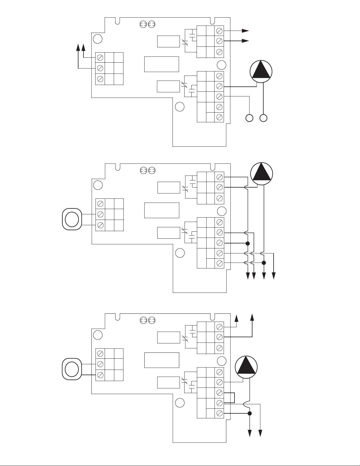
SR501-4 Switching Relay Wiring
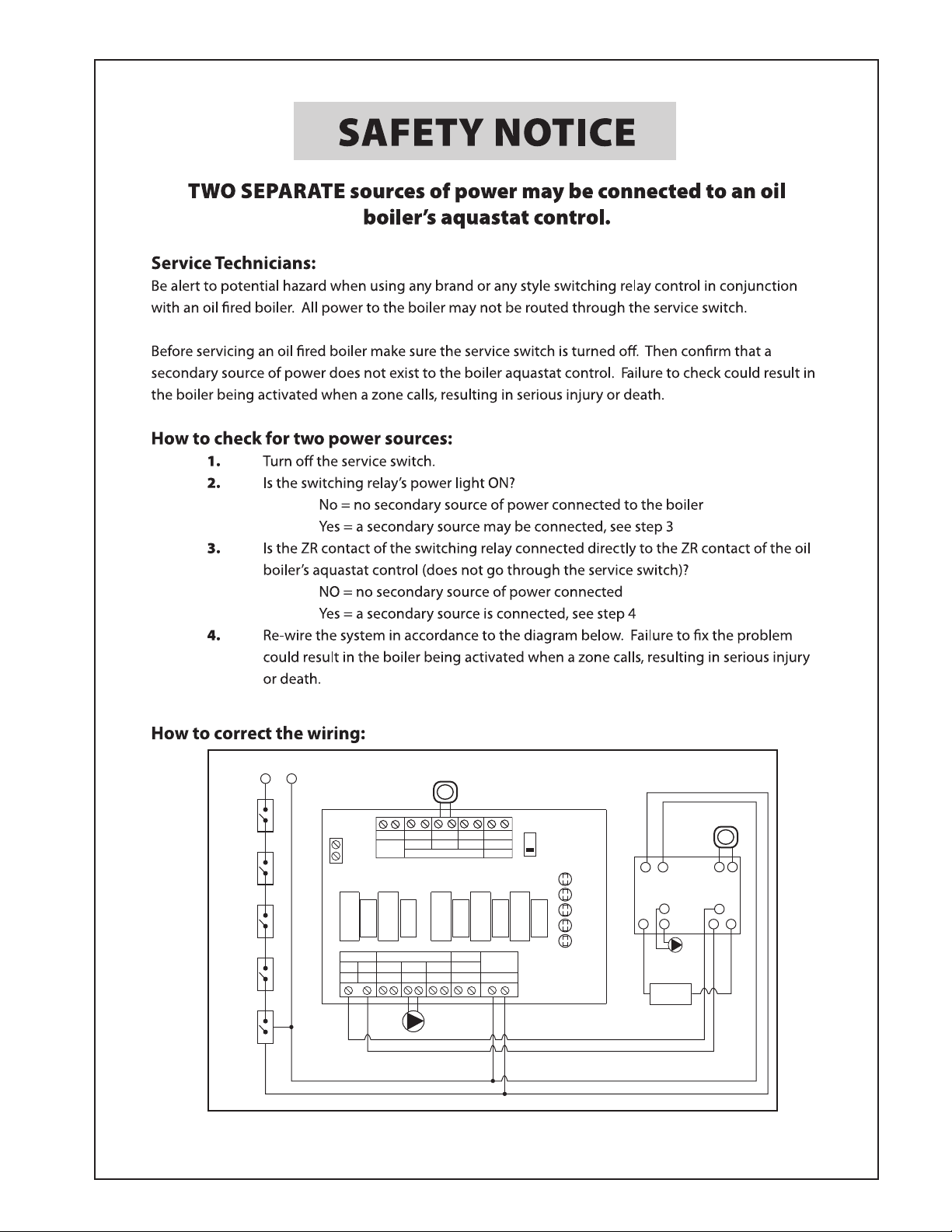
a secondary source of power being connected to the boiler that
aquastat. Failure to follow these wiring instructions may result in
may activate it under certain circumstances, causing injury or death.
Note: When using Alternative Wiring diagram, the boiler oper-
instructions must be followed so power originates from the boiler
ating control’s ZC terminal will see the load of the circulator(s).
Warning: When using Alternative Wiring diagram, wiring
2
ONE ZONE HC
S
WITCHING RELAY
SR 501-HC-4
LED
INDICATORS
R
W1
24 VAC THERMOSTAT
W2
COM
24
VAC
TT T
NHX1
RELAY 2RELAY 1
120 VAC
INPUT
120 VAC
C
IRCULATOR
X1
X2
X2
N
ZR
ZC
H
POWER INPUT
(120 VAC)
POWER
RELAY 1
RELAY 2
O
NE ZONE HC
SWITCHING RELAY
SR 501-HC-4
LED
INDICATORS
R
W
1
24 VAC THERMOSTAT
W
2
COM
24
VAC
TT T
NHX1
R
ELAY 2RELAY 1
120 VAC
I
NPUT
P
OWER
INPUT
(120 VAC)
120 VAC
CIRCULATOR
X1
X2
X2
N
H
BOILER
C
ONTROL
P
OWER
R
ELAY 1
RELAY 2
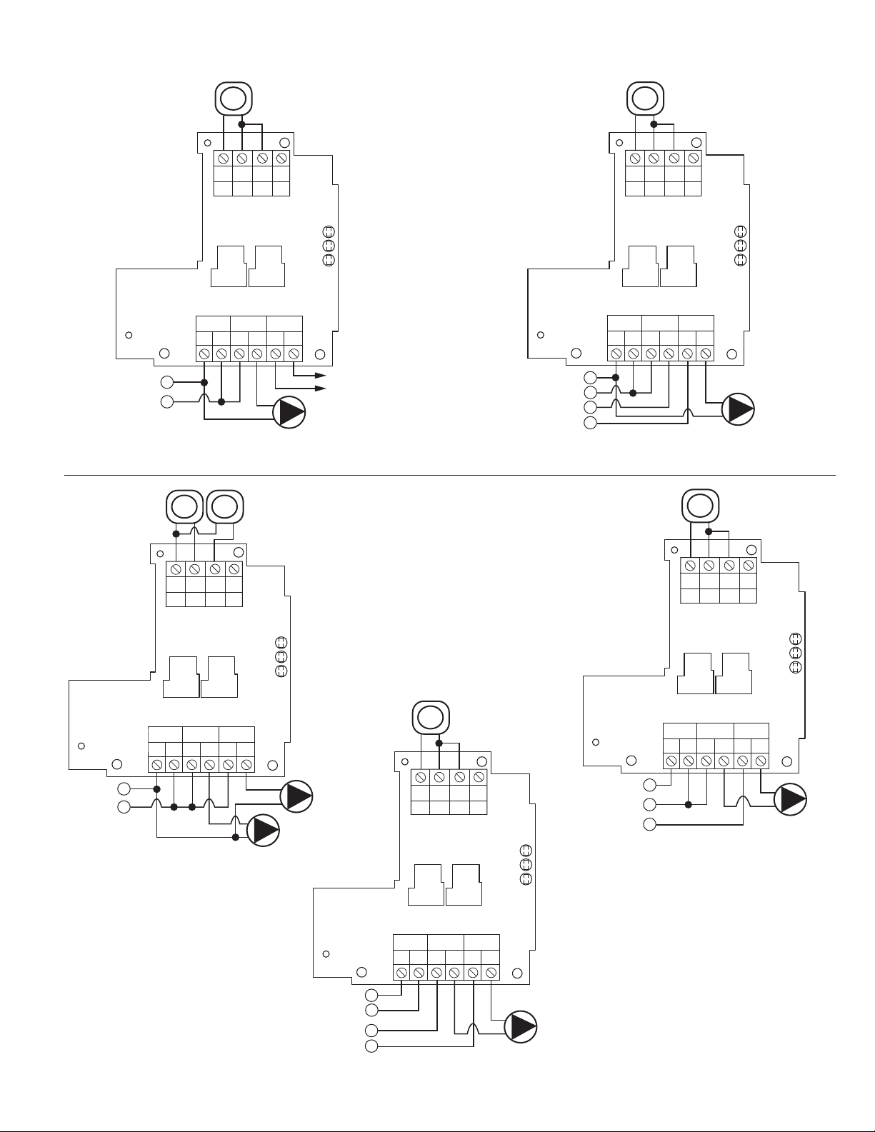
SR501-HC-4 – One Zone Switching Relay with or without Boiler Enable
ONE ZONE HC
SWITCHING RELAY
SR 501-HC-4
LED
INDICATORS
R
W1
24 VAC THERMOSTAT
W2
COM
24
VAC
TT T
NHX1
RELAY 2RELAY 1
120 VAC
INPUT
240 VAC
CIRCULATOR
X1
X2
X2
N
H1
H2
ONE ZONE, NO BOILER ENABLE
(CONTROL & CIRCULATOR SAME POWER SOURCE)
CONTROL POWER
INPUT (120 VAC)
POWER
RELAY 1
RELAY 2
(240 VAC)
{
{
ONE ZONE HC
SWITCHING RELAY
SR 501-HC-4
LED
INDICATORS
R
W1
24 VAC THERMOSTAT
W2
COM
24
VAC
TT T
NHX1
RELAY 2RELAY 1
120 VAC
INPUT
240 VAC
CIRCULATOR
X1
X2
X2
N
H1
H2
ONE ZONE, NO BOILER ENABLE
(CONTROL & CIRCULATOR DIFFERENT POWER SOURCE)
H
POWER
RELAY 1
RELAY 2
CONTROL POWER
INPUT (120 VAC)
(240 VAC)
{
{
ONE ZONE HC
SWITCHING RELAY
SR 501-HC-4
LED
INDICATORS
R
W1
W2
COM
24
V
AC
TT T
NHX1
RELAY 2RELAY 1
120 VAC
INPUT
CIRCULATOR #1
(120 VAC)
X1
X2
X2
N
TWO ZONE, NO BOILER ENABLE
H
CIRCULATOR #2
(120 VAC)
THERMOSTAT #2
(24 VAC)
T
HERMOSTAT #1
(24 VAC)
POWER
INPUT
(120 VAC)
POWER
RELAY 1
RELAY 2
Typical
Wiring
3
ELAY RATING:
R
(6.9 FLA, 41.4 LRA at 240 VAC)
P (13.8 FLA, 82.8 LRA at 120 VAC)
⁄4H
Alternative
Wiring
OTE: When using Alternative Wiring diagram, refer to important NOTE
N
and WARNING in SR501-HC Instruction Sheet on page 91 of this booklet.
3
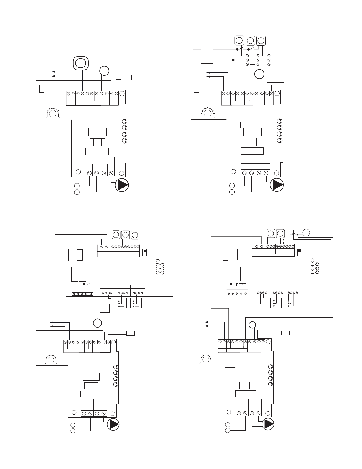
SR501-OR-4 – One Zone Switching Relay with Outdoor Reset
ONE ZONE INSTALLATION
W/O INDIRECT DHW
O
NE ZONE
S
WITCHING RELAY
WITH OUTDOOR RESET
SR 501-OR-4
LED
INDICATORS
POWER
T
STAT
DHW
OVERRIDE
BOILER
RELAY
NH
INPUT
120 VAC
ZONE 1
120 VAC
NH
6
AMP
X
R
BOILER TSTAT
WCRW
DHW
OUTDOOR
SENSOR
SUPPLY
S
ENSOR
X
DESIGN OUTDOOR
TEMPERATURE
FOR 180°F SUPPLY
TEMPERATURE
OFF
-
30
-20
0
-10 10
20
40
3
0
ON
SW1
OFF
S
YSTEM
C
IRCULATOR
N
H
P
OWER
INPUT
(120 VAC)
2
4 VAC
THERMOSTAT
B
OILER
CONTROL
OUTDOOR
SENSOR
BOILER
SUPPLY
SENSOR
POT1
ZONE VALVE INSTALLATION
W/O ZONE CONTROL, W/O INDIRECT DHW
ONE ZONE
SWITCHING RELAY
WITH OUTDOOR RESET
SR 501-OR-4
LED
INDICATORS
POWER
TSTAT
DHW
OVERRIDE
BOILER
RELAY
NH
INPUT
120 VAC
ZONE 1
120 VAC
NH
6
AMP
X
R
BOILER TSTAT
W
C
R
W
DHW
OUTDOOR
SENSOR
SUPPLY
SENSOR
X
DESIGN OUTDOOR
TEMPERATURE
FOR 180°F SUPPLY
TEMPERATURE
O
FF
-30
-20
0
-
10 10
20
4
0
30
ON
SW1
OFF
ZONE VALVE
CIRCULATOR
N
H
POWER
INPUT
(
120 VAC)
BOILER
CONTROL
OUTDOOR
SENSOR
BOILER
SUPPLY
SENSOR
POT1
Z
ONE VALVE
END SWITCH(S)
THERMOSTATS
(24VAC)
TRANSFORMER
24 VAC
120 VAC
INPUT
MULTI-ZONE INSTALLATION
WITH ZONE CONTROL, W/O INDIRECT DHW
ONE ZONE
SWITCHING RELAY
WITH OUTDOOR RESET
SR 501-OR-4
LED
INDICATORS
POWER
TSTAT
DHW
OVERRIDE
BOILER
RELAY
NH
INPUT
120 VAC
ZONE 1
120 VAC
NH
6
AMP
X
R
BOILER TSTAT
W
CR
W
DHW
OUTDOOR
SENSOR
SUPPLY
SENSOR
X
DESIGN OUTDOOR
TEMPERATURE
FOR 180°F SUPPLY
TEMPERATURE
OFF
-30
-20
0
-10 10
20
40
30
ON
SW1
OFF
ZONE VALVE
CIRCULATOR
N
H
POWER
INPUT
(120 VAC)
BOILER
CONTROL
OUTDOOR
SENSOR
BOILER
SUPPLY
SENSOR
POT1
1234
ZONE 1
1234
ZONE 2
1234
ZONE 3
EXISTING
ZONE VALVE CONTROL
POWER IN
24 VAC
N/O
COM
N/C
PUMP END
S
WITCH
FUSE
5 AMP
ZONE 3 PUMP
END SWITCH
THERMOSTATS
(24VAC)
T
STAT 1
V
ALVE 1
T
STAT 2
VALVE 2
T
STAT 3
VALVE 3
P
OWER
L
ED
INDICATORS
ZONE 1 ZONE 2 ZONE 3
ISOLATED
XXRWRW RW
END SWITCH THERMOSTATS
PRIORITY
24 VAC ZONE VALVES
PRIORITY
XX
ZONE 3
P
RIORITY
OFF
ON
CCC
2 WIRE ZONE VALVE
(
NO END SWITCH)
M
UST USE JUMPER
TACO 3 WIRE
ZONE VALVE
1
2
3
JUMPER
3
& 4
TACO 3 WIRE
ZONE VALVE
1
2
3
MULTI-ZONE INSTALLATION
WITH ZONE CONTROL, WITH INDIRECT DHW
ONE ZONE
SWITCHING RELAY
WITH OUTDOOR RESET
SR 501-OR-4
LED
INDICATORS
POWER
TSTAT
DHW
OVERRIDE
BOILER
RELAY
NH
INPUT
120 VAC
ZONE 1
120 VAC
NH
6
AMP
X
R
BOILER TSTAT
WCRW
DHW
OUTDOOR
SENSOR
SUPPLY
SENSOR
X
DESIGN OUTDOOR
TEMPERATURE
FOR 180°F SUPPLY
TEMPERATURE
OFF
-30
-20
0
-10 10
20
40
30
ON
SW1
OFF
ZONE VALVE
CIRCULATOR
N
H
POWER
INPUT
(120 VAC)
BOILER
CONTROL
OUTDOOR
SENSOR
BOILER
SUPPLY
SENSOR
POT1
1234
Z
ONE 1
1234
Z
ONE 2
1234
Z
ONE 3
E
XISTING
Z
ONE VALVE CONTROL
POWER IN
24 VAC
N/O
COM
N/C
PUMP END
S
WITCH
FUSE
5 AMP
ZONE 3 PUMP
END SWITCH
THERMOSTATS
(24VAC)
T
STAT 1
V
ALVE 1
T
STAT 2
V
ALVE 2
T STAT 3
V
ALVE 3
POWER
LED
INDICATORS
ZONE 1 ZONE 2 ZONE 3
ISOLATED
XXRWRW RW
END SWITCH THERMOSTATS
PRIORITY
24 VAC ZONE VALVES
PRIORITY
XX
Z
ONE 3
PRIORITY
OFF
ON
CCC
2 WIRE ZONE VALVE
(NO END SWITCH)
M
UST USE JUMPER
T
ACO 3 WIRE
ZONE VALVE
1
2
3
JUMPER
3 & 4
TACO 3 WIRE
ZONE VALVE
1
2
3
D
HW
A
QUASTAT
A
4
NOTE: Tankless coil has priority.
L1 L2
T T
LINE VOLTAGE
OIL BURNER RELAY
CIRCULATOR
ON BOILER
(IF ATTACHED)
B2
C1
B1ZR
HONEYWELL L8124
OR EQUAL
120 VAC INPUT
C2
ZC
L1 L2
(NEUTRAL)(HOT)
C
IRCUIT
BREAKER
CUSTOMER
EMERGENCY
SWITCH
THERMAL
FUSE
(FIROMATIC)
SERVICE
SWITCH
LOW
WATER
CUTOFF
T
FOUR ZONE SWITCHING RELAY
120 VAC CIRCULATORS
ZC
INPUT
120 VAC
ZONE 1 ZONE 2 ZONE 3 ZONE 4
ZONE1 ZONE2 ZONE3
THERMOSTATS
SR 504-4
FUSE
6 AMP
FUSE
6 AMP
FUSE
6 AMP
FUSE
6 AMP
FUSE
6 AMP
XXRWRWRWRW
ISOLATED
END
SWITCH
THERMOSTATS (24 VAC)
PRIORITY
120 VAC
ZR
HHNHNHNHNHNH
ZONE4
ZONE 2
POWER
ZONE 1
ZONE 3
ZONE 4
LED
INDICATORS
ZONE 4
PRIORITY
OFF
ON
PRIORITY
2
4 VAC
COM
THERMOSTATS
T
5
BOILER
H
N
TT T
TT T
OUTPUT
NOT
USED
120 VAC INPUT
FOUR ZONE SWITCHING RELAY
120 VAC CIRCULATORS
ZC
INPUT
120 VAC
ZONE 1 ZONE 2 ZONE 3 ZONE 4
ZONE1 ZONE2 ZONE3
THERMOSTATS
SR 504-4
FUSE
6
AMP
FUSE
6 AMP
FUSE
6 AMP
FUSE
6
AMP
FUSE
6
AMP
XX
RW
RW
RW
RW
ISOLATED
E
ND
SWITCH
THERMOSTATS (24 VAC)
PRIORITY
120 VAC
ZR
HHNHNHNHNH NH
ZONE4
ZONE 2
P
OWER
ZONE 1
ZONE 3
ZONE 4
LED
INDICATORS
Z
ONE 4
PRIORITY
OFF
ON
PRIORITY
T
O: "TT" ON BOILER
JUMPER
24 VAC
COM
DHW
HEATER
CIRCULATOR
THERMOSTATS
120 VAC INPUT
FOUR ZONE SWITCHING RELAY
120 VAC CIRCULATORS
ZC
INPUT
120 VAC
ZONE 1 ZONE 2 ZONE 3 ZONE 4
ZONE1 ZONE2 ZONE3
SR 504-4
FUSE
6 AMP
FUSE
6 AMP
FUSE
6 AMP
FUSE
6 AMP
FUSE
6 AMP
XX
RW
RW
RW
RW
ISOLATED
END
SWITCH
THERMOSTATS (24 VAC)
PRIORITY
120 VAC
ZR
HHNHNHNHNH NH
ZONE4
ZONE 2
POWER
ZONE 1
ZONE 3
ZONE 4
LED
INDICATORS
ZONE 4
PRIORITY
OFF
ON
PRIORITY
JUMPER
24 VAC
COM
TO: "TT" ON BOILER
I
NDIRECT
W
ATER HEATER
A
QUASTAT OR
THERMOSTAT
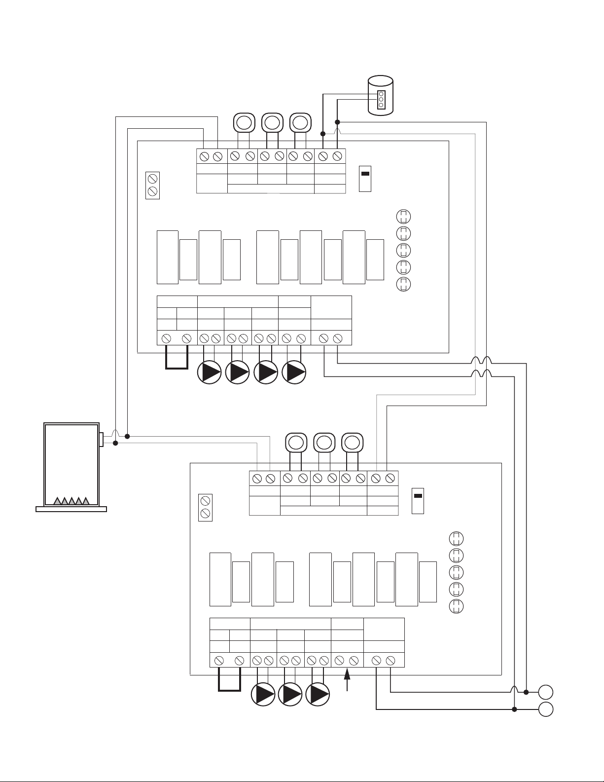
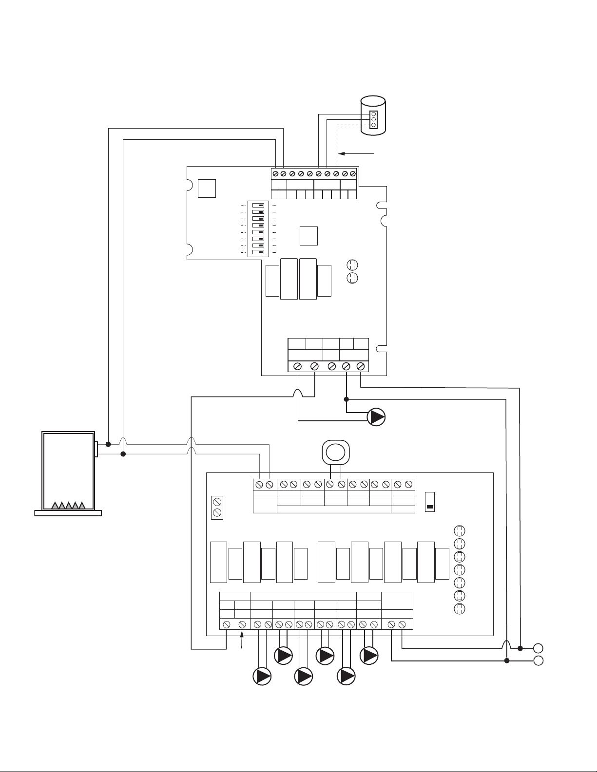
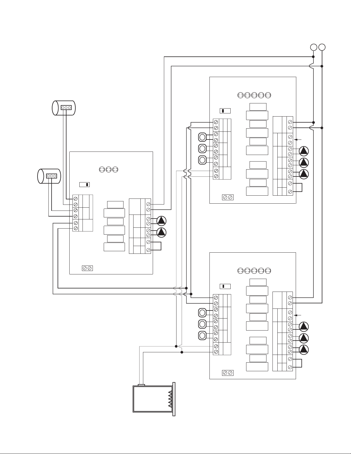
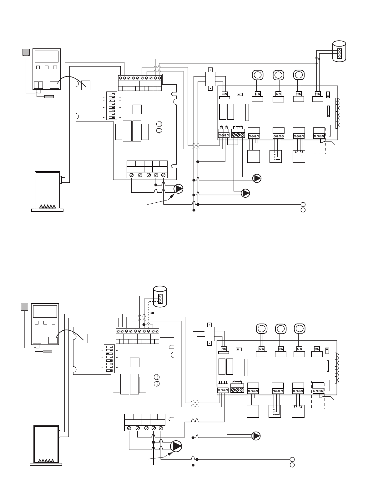
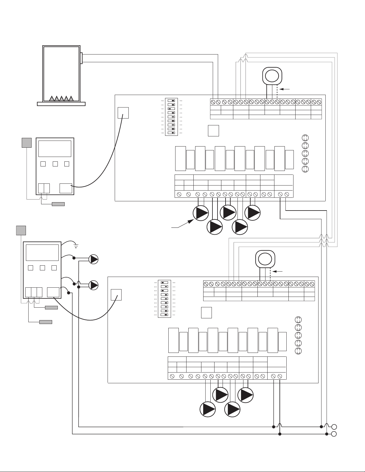
Two Switching Relays Connected Together
6
TO: "TT" ON BOILER
1
20 VAC INPUT
BOILER
H
N
MASTER
SLAVE
PRIORITY
ON
PRIORITY
OFF
120 VAC
INPUT
SIX ZONE SWITCHING RELAY
120 VAC CIRCULATORS
ZC
INPUT
120 VAC
ZONE 1 ZONE 2 ZONE 3 ZONE 4 ZONE 5 ZONE 6
ZONE1 ZONE2 ZONE3 ZONE4 ZONE5
THERMOSTATS
SR 506-4
FUSE
6 AMP
FUSE
6 AMP
FUSE
6 AMP
FUSE
6 AMP
FUSE
6 AMP
FUSE
6 AMP
FUSE
6 AMP
XX
RW
RW
RW
RW
RW
RW
ISOLATED
E
ND
SWITCH
THERMOSTATS (24 VAC)
PRIORITY
120 VAC
ZR
HHNHNHNHNHNHNHNH
ZONE6
ZONE 2
POWER
ZONE 1
ZONE 3
ZONE 4
ZONE 5
ZONE 6
LED
INDICATORS
ZONE 6
PRIORITY
OFF
ON
PRIORITY
24 VAC
COM
REMOVE
JUMPER
P
PRIORITY
24 VAC
OUTPUT
(OPTIONAL)
POWER IN
H
(on)
MASTE
R
CIRC.
ON
P
RIORITY
M
ASTER/SLAVE
SWITCH
RW
X
X
RC
THERMO-
STAT
END
SWITCH
24 VAC
POWER
N
P
RIORITY ZONING
CIRCULATOR
I
NDIRECT
W
ATER HEATER
AQUASTAT OR
T
HERMOSTAT
Priority Zoning Circulator Controlling Switching Relay
7
INDIRECT
WATER HEATER
AQUASTAT OR
THERMOSTAT
120 VAC INPUT
TO: "TT" ON BOILER
H
N
SLAVE
120 VAC INPUT
REMOVE
JUMPER
MASTER
PRIORITY
ON
P
PRIORITY
POWER IN
H
(on)
MASTE
R
CIRC.
ON
PRIORITY
MASTER/SLAVE
SWITCH
R W X X
R C
THERMO-
STAT
END
SWITCH
24 VAC
POWER
N
PRIORITY ZONING
CIRCULATOR
TT T
120 VAC INPUT
FOUR ZONE SWITCHING RELAY
120 VAC CIRCULATORS
ZC
INPUT
120 VAC
ZONE 1 ZONE 2 ZONE 3 ZONE 4
ZONE1
ZONE2
ZONE3
THERMOSTATS
SR 504-4
FUSE
6 AMP
FUSE
6 AMP
FUSE
6 AMP
FUSE
6 AMP
FUSE
6 AMP
X X
R W
R W
R W
R W
ISOLATED
END
SWITCH
THERMOSTATS (24 VAC)
PRIORITY
120 VAC
ZR
H H N H N H N H N H N H
ZONE4
ZONE 2
POWER
ZONE 1
ZONE 3
ZONE 4
LED
INDICATORS
ZONE 4
PRIORITY
OFF
ON
PRIORITY
24 VAC
COM
T
BOILER
SLAVE
REMOVE
JUMPER
TT T
FOUR ZONE SWITCHING RELAY
120 VAC CIRCULATORS
ZC
INPUT
120 VAC
ZONE 1 ZONE 2 ZONE 3 ZONE 4
ZONE1
ZONE2
ZONE3
THERMOSTATS
SR 504-4
FUSE
6 AMP
FUSE
6 AMP
FUSE
6 AMP
FUSE
6 AMP
FUSE
6 AMP
X X
R W
R W
R W
R W
ISOLATED
END
SWITCH
THERMOSTATS (24 VAC)
PRIORITY
120 VAC
ZR
H H N H N H N H N H N H
ZONE4
ZONE 2
POWER
ZONE 1
ZONE 3
ZONE 4
LED
INDICATORS
ZONE 4
PRIORITY
OFF
ON
PRIORITY
24 VAC
COM
T
TO: "TT" ON BOILER
PRIORITY
OFF
PRIORITY
OFF
24 VAC
OUTPUT
(OPTIONAL)
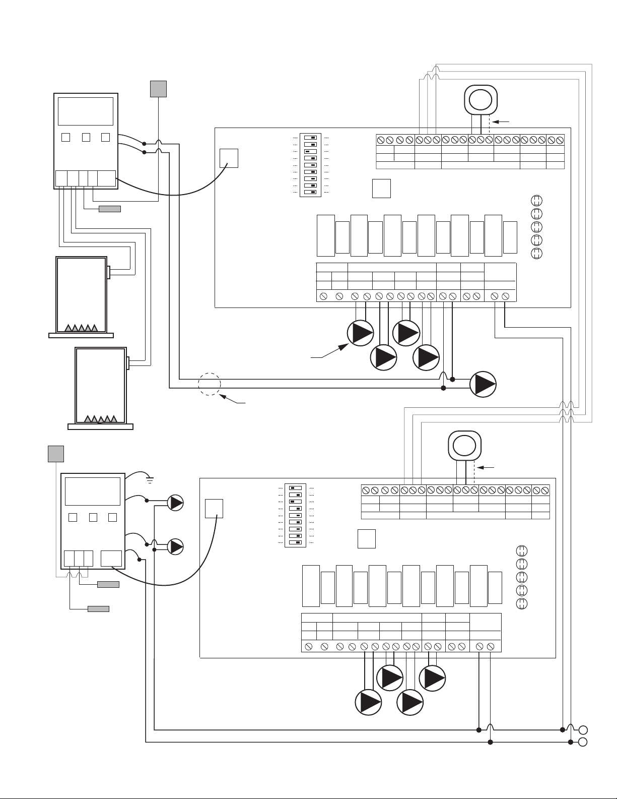
Priority Zoning Circulator Controlling 2 Switching Relays
8
120 VAC INPUT
TO: "TT" ON BOILER
H
N
SLAVE
120 VAC INPUT
REMOVE
JUMPER
MASTER
TT T
120 VAC INPUT
FOUR ZONE SWITCHING RELAY
120 VAC CIRCULATORS
ZC
INPUT
120 VAC
ZONE 1 ZONE 2 ZONE 3 ZONE 4
ZONE1
ZONE2
ZONE3
THERMOSTATS
SR 504-4
FUSE
6 AMP
FUSE
6 AMP
FUSE
6 AMP
FUSE
6 AMP
FUSE
6 AMP
X X
R W
R W
R W
R W
ISOLATED
END
SWITCH
THERMOSTATS (24 VAC)
PRIORITY
120 VAC
ZR
H H N H N H N H N H N H
ZONE4
ZONE 2
POWER
ZONE 1
ZONE 3
ZONE 4
LED
INDICATORS
ZONE 4
PRIORITY
OFF
ON
PRIORITY
24 VAC
COM
T
BOILER
SLAVE
REMOVE
JUMPER
TT T
FOUR ZONE SWITCHING RELAY
120 VAC CIRCULATORS
ZC
INPUT
120 VAC
ZONE 1 ZONE 2 ZONE 3 ZONE 4
ZONE1
ZONE2
ZONE3
THERMOSTATS
SR 504-4
FUSE
6 AMP
FUSE
6 AMP
FUSE
6 AMP
FUSE
6 AMP
FUSE
6 AMP
X X
R W
R W
R W
R W
ISOLATED
END
SWITCH
THERMOSTATS (24 VAC)
PRIORITY
120 VAC
ZR
H H N H N H N H N H N H
ZONE4
ZONE 2
POWER
ZONE 1
ZONE 3
ZONE 4
LED
INDICATORS
ZONE 4
PRIORITY
OFF
ON
PRIORITY
24 VAC
COM
T
ONE ZONE
SWITCHING RELAY
SR 501-4
FUSE
6 AMP
POWER
ZONE 1
LED
INDICATORS
FUSE
6 AMP
N H 3 4 4 56 6
N/O N/ON/C N/CCOM COM
120 VAC
INPUT
T T
COM
R
W
24
VAC
CIRCULATOR
JUMPER
INDIRECT
WATER HEATER
AQUASTAT OR
THERMOSTAT
PRIORITY
OFF
PRIORITY
OFF
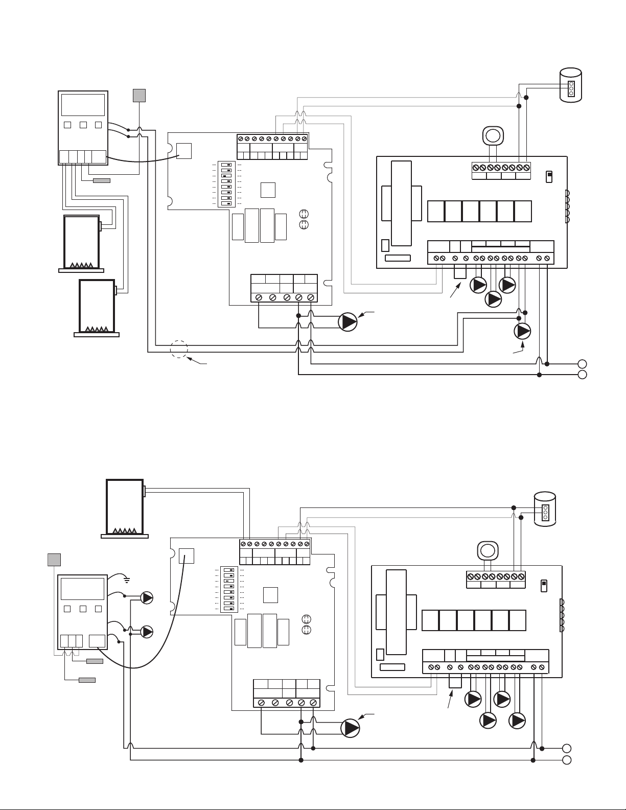
SR501 Switching Relay Controlling 2 Switching Relays
9
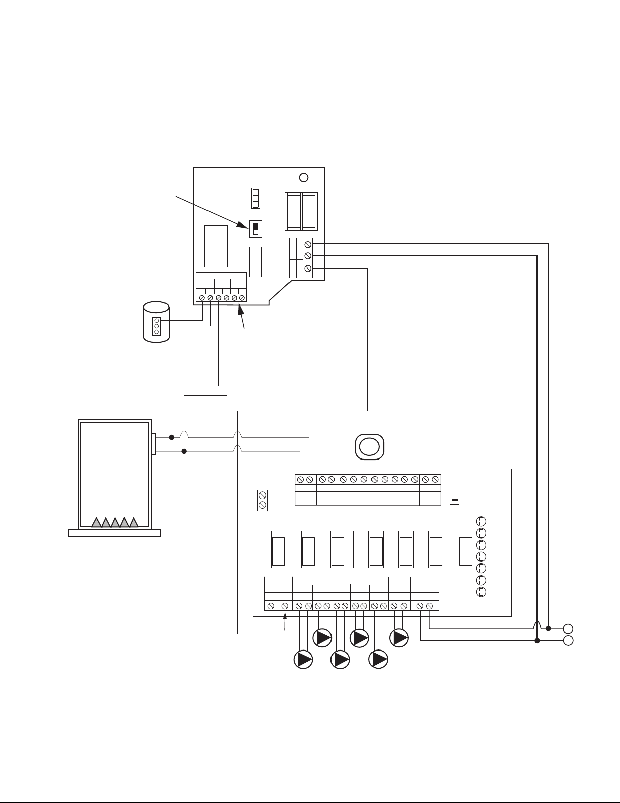
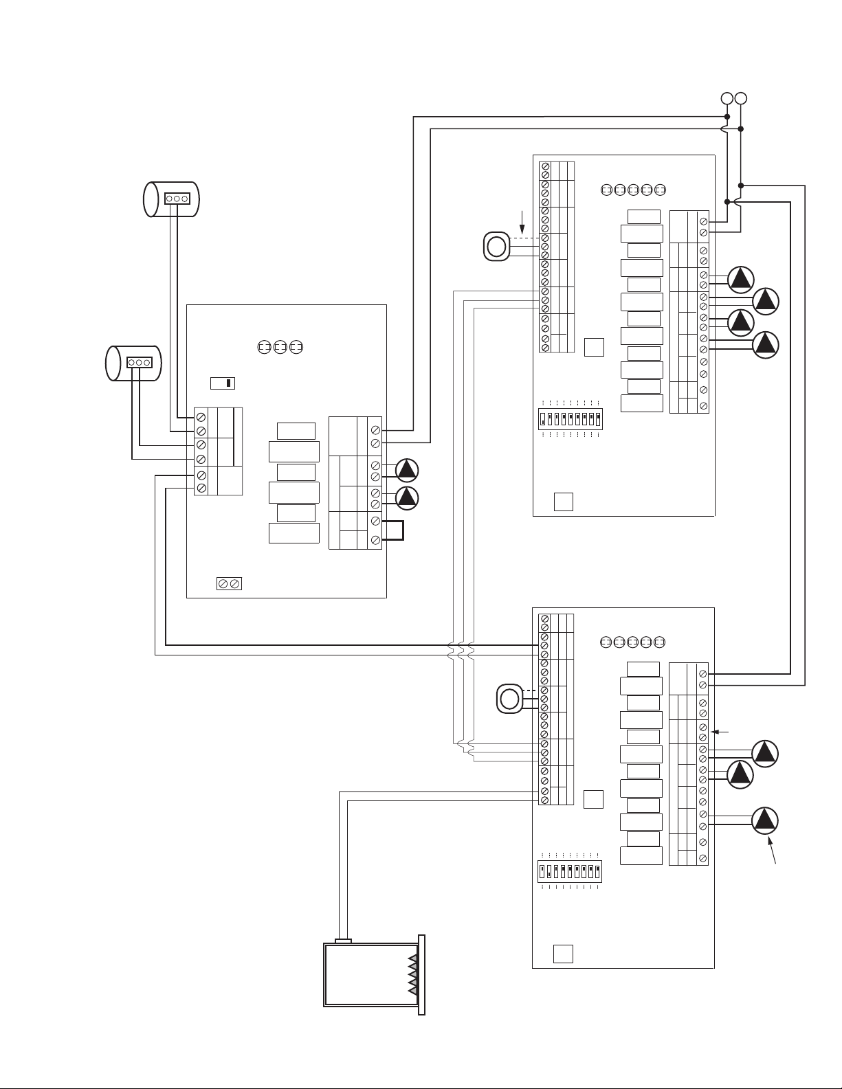
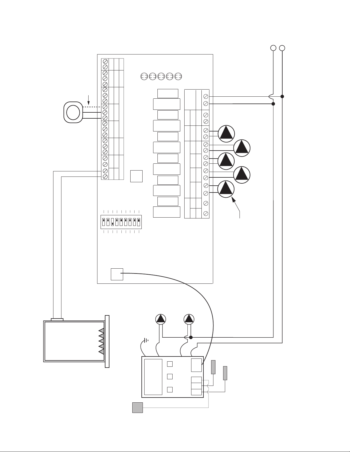
SR501-EXP Switching Relay Controlling Another Switching Relay
120 VAC INPUT
TO: "TT"
ON BOILER
BOILER
H
N
MASTER
TO: "TT" ON BOILER
POWER
ZONE 1
LED
INDICATORS
F
USE
6 AMP
F
USE
6 AMP
SR 501-EXP-4
P
OWER
CONTROLS
SLAVE
PRIORITY ON
RESET
PRIMARY PUMP ON
POST PURGE ON
P
RIORITY PROTECT ON
PUMP EXERCISE ON
30 SEC/2 WK
MASTER
OFF
OFF
OFF
O
FF
OFF
NORMAL
4 MIN/24 HOUR
A
CCESSORY
PORT
DHW HEATER
CIRCULATOR
HN/O NH
120 VAC
CIRCULATOR
PRIMARY
OUTPUT
N/C
INPUT
1
20 VAC
E
ND
SWITCH
R
ESET
OVERRIDE
THERMOSTATEXPANSION
X
W
R
X1A 2CB
24 VOLTS AC ONLY
C
SINGLE ZONE
EXPANDABLE SWITCHING RELAY
120 VAC INPUT
SLAVE
PRIORITY
OFF
SIX ZONE SWITCHING RELAY
120 VAC CIRCULATORS
ZC
INPUT
120 VAC
ZONE 1 ZONE 2 ZONE 3 ZONE 4 ZONE 5 ZONE 6
ZONE1 ZONE2 ZONE3 ZONE4 ZONE5
THERMOSTATS
SR 506-4
FUSE
6 AMP
FUSE
6 AMP
FUSE
6 AMP
FUSE
6 AMP
FUSE
6 AMP
FUSE
6 AMP
FUSE
6 AMP
XX
RW
RW
RW
RW
RW
RW
ISOLATED
END
SWITCH
THERMOSTATS (24 VAC)
PRIORITY
120 VAC
ZR
HHNHNHNHNHNHNH NH
ZONE6
ZONE 2
POWER
ZONE 1
ZONE 3
ZONE 4
ZONE 5
ZONE 6
LED
INDICATORS
ZONE 6
PRIORITY
OFF
ON
PRIORITY
24 VAC
COM
REMOVE
JUMPER
T
INDIRECT
W
ATER HEATER
A
QUASTAT OR
THERMOSTAT
N
OTE 1: Terminals C are for
optional 24V thermostat
C
OMMON connections.
10
SR501-EXP Switching Relay Controlling a Zone Valve Control
TO BOILER AQUASTAT RELAY
BOILER
H
N
BOILER TURNS ON WHEN ANY ZONE VALVE OPENS.
120 VAC
INPUT
TO BOILER AQUASTAT RELAY
SLAVE
SYSTEM PUMP TURNS ON WHEN ANY ZONE VALVE OPENS
EXCEPT WHEN THE DHW HEATER (SR501-EXP) CALLS.
MASTER
P
OWER
ZONE 1
LED
INDICATORS
F
USE
6
AMP
F
USE
6
AMP
SR 501-EXP-4
P
OWER
CONTROLS
SLAVE
PRIORITY ON
RESET
PRIMARY PUMP ON
POST PURGE ON
PRIORITY PROTECT ON
P
UMP EXERCISE ON
30 SEC/2 WK
MASTER
OFF
OFF
OFF
OFF
O
FF
N
ORMAL
4 MIN/24 HOUR
ACCESSORY
PORT
D
HW HEATER
CIRCULATOR
HN/O NH
1
20 VAC
CIRCULATOR
PRIMARY
O
UTPUT
N/C
INPUT
120 VAC
END
SWITCH
RESET
OVERRIDE
T
HERMOSTATEXPANSION
X
W
R
X1A 2CB
24 VOLTS AC ONLY
C
S
INGLE ZONE
EXPANDABLE SWITCHING RELAY
120 VAC INPUT
1234
ZONE 1
1234
ZONE 2
1234
ZONE 3
1234
ZONE 4
1234
ZONE 5
1234
ZONE 6
PRIORITY
ZONE
2 WIRE ZONE VALVE
(NO END SWITCH)
MUST USE JUMPER
TACO
3 WIRE
ZONE VALVE
1
2
3
JUMPER
3 & 4
MOTOR END
SWITCH
4 WIRE ZONE VALVE
(POWER OPEN,
SELF CLOSING)
JUMPER
3 & 4
ZVC 406 – 4
SIX ZONE
ZONE VALVE CONTROL
24 VAC
FACTORY
INSTALLED
TRANSFORMER
120 VAC
INPUT
WHITE
BLACK
POWER IN
24 VAC
24 VAC
FACTORY
INSTALLED
TRANSFORMER
120 VAC
INPUT
WHITE
BLACK
DRY
CONTACTS
N/O
COM
N/C
PUMP END
SWITCH
ZONE 6 PUMP
END SWITCH
THERMOSTATS (24VAC)
T STAT 1
VALVE 1
T STAT 2
VALVE 2
T STAT 3
VALVE 3
T STAT 4
VALVE 4
VALVE 5
T STAT 6
VALVE 6
POWER
LED
INDICATORS
T STAT 5
ZONE 1 ZONE 2 ZONE 3 ZONE 4 ZONE 5 ZONE 6
ISOLATED
XX
END SWITCH THERMOSTATS (24 VAC) PRIORITY
24 VAC ZONE VALVES
PRIORITY
XX
ZONE 6
PRIORITY
OFF
ON
NOTE 2: When a circulator
is used on the priority zone
instead of a zone valve,
jumper 3 and 4 of the
priority zone.
FUSE
5 AMP
RW
See NOTE 1
RW
RW RWC CC
RW
C
C
FUSE
5 AMP
RW
C
Powered from Transformer A Powered from Transformer B
A
B
Powered from Transformer A Powered from Transformer B
SYSTEM
PUMP
T
TT
INDIRECT
W
ATER HEATER
A
QUASTAT OR
THERMOSTAT
PRIORITY
ON
NOTE 1: Terminals C are for
optional 24V thermostat
C
OMMON connections.
11
1
20 VAC INPUT
BOILER
SWITCH SETTINGS
Master/Slave: Slave
Priority Zone: Off
Reset/Normal: Normal
120 VAC INPUT
H
N
SWITCH SETTINGS
Master/Slave: Master
Priority Zone: On
Reset/Normal: Normal
TO: "TT" ON BOILER
DHW
CIRCULATOR
SLAVE
MASTER
F
OUR ZONE
EXPANDABLE
S
WITCHING RELAY
P
OWER
CONTROLS
1
20 VAC CIRCULATORS
ZC
INPUT
120 VAC
Z
ONE 1
Z
ONE 2 ZONE 3 ZONE 4
Z
ONE1 Z
ONE2 Z
ONE3
THERMOSTATS
SR 504-EXP-4
FUSE
6 AMP
F
USE
6
AMP
FUSE
6 AMP
FUSE
6 AMP
F
USE
6
AMP
F
USE
6
AMP
NET
E
XPANSION
M
AIN PRIORITY
XXXXAB
CRW
CRW
CRW
CRWC12
END SWITCH THERMOSTATS (24 VAC)
PRIORITY
N/C
P
RIMARY
1
20 VAC
ZR
HHNHNHNHNHNHNH NH
SLAVE
PRIORITY ON
RESET
PRIMARY PUMP ON
POST PURGE ON
P
RIORITY PROTECT ON
P
UMP EXERCISE ON
3
0 SEC/2 WK
MASTER
O
FF
OFF
OFF
O
FF
O
FF
N
ORMAL
LOW LIMIT (ZC) ON OFF
4
MIN/24 HOUR
Z
ONE4 ZONE4
PRIORITY
A
CCESSORY
PORT
ZONE 2
POWER
Z
ONE 1
Z
ONE 3
ZONE 4
L
ED
INDICATORS
PRIMARY SYSTEM
CIRCULATOR
(OPTIONAL)
TO: "TT" ON BOILER WITH
DHW "TT" INPUT
SIX ZONE
EXPANDABLE SWITCHING RELAY
P
OWER
CONTROLS
120 VAC CIRCULATORS
ZC
INPUT
120 VAC
ZONE 1 ZONE 2 ZONE 3 ZONE 4 ZONE 5 ZONE 6
ZONE1 ZONE2 ZONE3 ZONE4 ZONE5
THERMOSTATS
SR 506-EXP-4
FUSE
6 AMP
FUSE
6 AMP
FUSE
6 AMP
FUSE
6 AMP
FUSE
6 AMP
FUSE
6 AMP
FUSE
6 AMP
FUSE
6 AMP
NET
EXPANSIONMAIN PRIORITY
XX
XX
AB
CRW
CRW
CRW
CRW
CRW
CRW
C
12
END SWITCH THERMOSTATS (24 VAC)
PRIORITY
N/C
PRIMARY
120 VAC
ZR
HHNHNHNHNHNHNHNHNH NH
SLAVE
P
RIORITY ON
RESET
PRIMARY PUMP ON
POST PURGE ON
PRIORITY PROTECT ON
PUMP EXERCISE ON
30 SEC/2 WK
MASTER
OFF
OFF
OFF
OFF
OFF
N
ORMAL
LOW LIMIT (ZC) ON OFF
4 MIN/24 HOUR
ZONE6 ZONE6
PRIORITY
ACCESSORY
PORT
ZONE 2
POWER
ZONE 1
ZONE 3
ZONE 4
ZONE 5
ZONE 6
LED
INDICATORS
T
T
INDIRECT
WATER HEATER
AQUASTAT OR
THERMOSTAT
NOTE 1: Terminals C are for
optional 24V thermostat
C
OMMON connections.
See NOTE 1
See NOTE 1
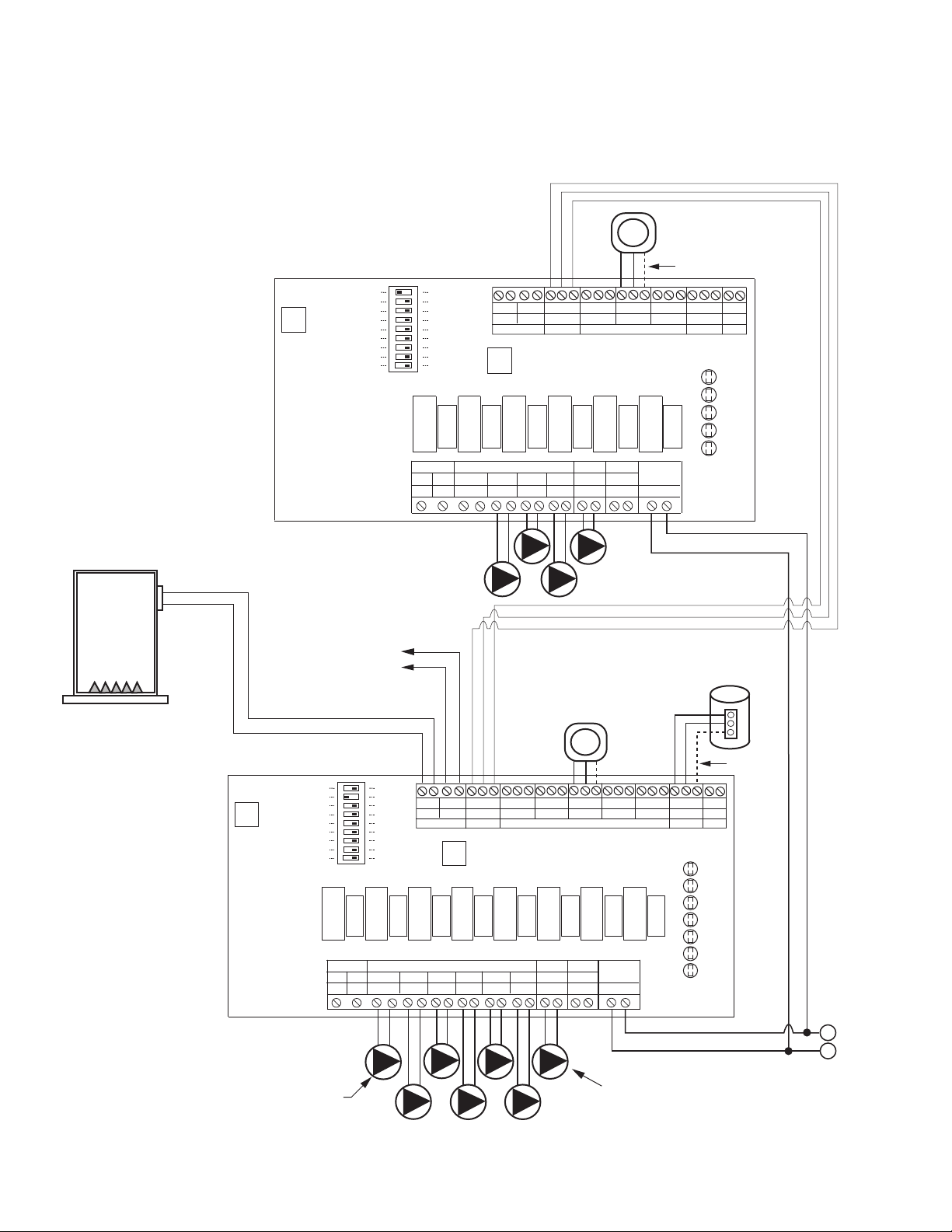
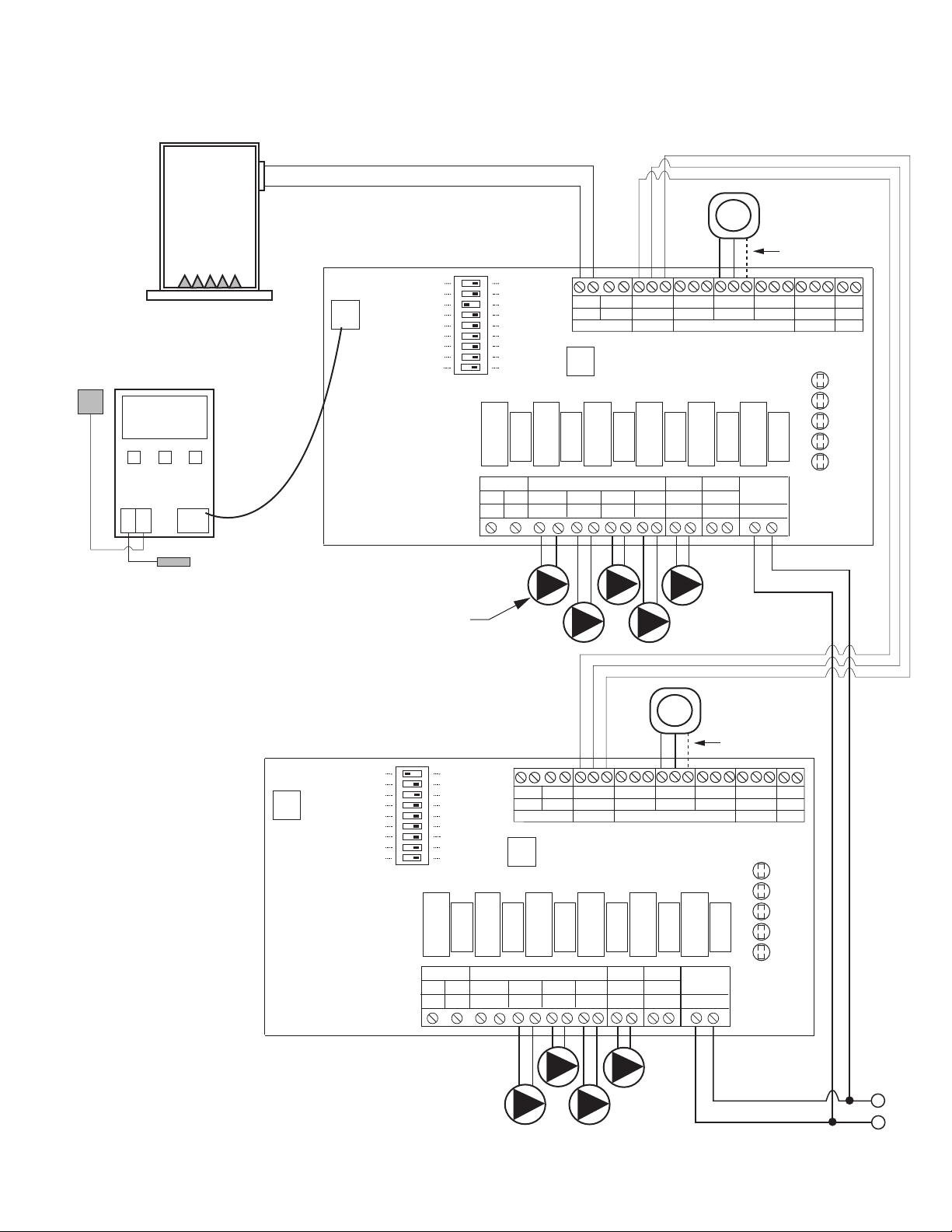
2 Expandable Switching Relays Connected Together
12
120 VAC INPUT
BOILER
SWITCH SETTINGS
Master/Slave: Master
Priority Zone: On
Reset/Normal: Normal
120 VAC INPUT
H
N
SWITCH SETTINGS
Master/Slave: Slave
Priority Zone: Off
Reset/Normal: Normal
TO: "TT" ON BOILER
SLAVE
MASTER
FOUR ZONE
EXPANDABLE
SWITCHING RELAY
POWER
CONTROLS
120 VAC CIRCULATORS
ZC
INPUT
120 VAC
ZONE 1
ZONE 2 ZONE 3 ZONE 4
ZONE1
ZONE2
ZONE3
THERMOSTATS
SR 504-EXP-4
FUSE
6 AMP
FUSE
6 AMP
FUSE
6 AMP
FUSE
6 AMP
FUSE
6 AMP
FUSE
6 AMP
NET
EXPANSIONMAIN PRIORITY
X X
X X
A B
C R W
C R W
C R W
C R W
C
1 2
END SWITCH THERMOSTATS (24 VAC)
PRIORITY
N/C
PRIMARY
120 VAC
ZR
H H N H N H N H N H N H N H N H
SLAVE
PRIORITY ON
RESET
PRIMARY PUMP ON
POST PURGE ON
PRIORITY PROTECT ON
PUMP EXERCISE ON
30 SEC/2 WK
MASTER
OFF
OFF
OFF
OFF
OFF
NORMAL
LOW LIMIT (ZC) ON OFF
4 MIN/24 HOUR
ZONE4 ZONE4
PRIORITY
ACCESSORY
PORT
ZONE 2
POWER
ZONE 1
ZONE 3
ZONE 4
LED
INDICATORS
TO: "TT" ON BOILER WITH
DHW "TT" INPUT
SIX ZONE
EXPANDABLE SWITCHING RELAY
POWER
CONTROLS
120 VAC CIRCULATORS
ZC
INPUT
120 VAC
ZONE 1 ZONE 2
ZONE 3
ZONE 4 ZONE 5 ZONE 6
ZONE1
ZONE2
ZONE3
ZONE4
ZONE5
THERMOSTATS
SR 506-EXP-4
FUSE
6 AMP
FUSE
6 AMP
FUSE
6 AMP
FUSE
6 AMP
FUSE
6 AMP
FUSE
6 AMP
FUSE
6 AMP
FUSE
6 AMP
NET
EXPANSIONMAIN PRIORITY
X X
X X
A B
C R W
C R W
C R W
C R W
C R W
C R W
C
1 2
END SWITCH THERMOSTATS (24 VAC)
PRIORITY
N/C
PRIMARY
120 VAC
ZR
H H N H N H N H N H N H N H N H N H N H
SLAVE
PRIORITY ON
RESET
PRIMARY PUMP ON
POST PURGE ON
PRIORITY PROTECT ON
PUMP EXERCISE ON
30 SEC/2 WK
MASTER
OFF
OFF
OFF
OFF
OFF
NORMAL
LOW LIMIT (ZC) ON OFF
4 MIN/24 HOUR
ZONE6 ZONE6
PRIORITY
ACCESSORY
PORT
ZONE 2
POWER
ZONE 1
ZONE 3
ZONE 4
ZONE 5
ZONE 6
LED
INDICATORS
T
T
INDIRECT
WATER HEATER
AQUASTAT OR
THERMOSTAT
FOUR ZONE
EXPANDABLE
SWITCHING RELAY
POWER
CONTROLS
120 VAC CIRCULATORS
ZC
INPUT
120 VAC
ZONE 1
ZONE 2 ZONE 3 ZONE 4
ZONE1
ZONE2
ZONE3
THERMOSTATS
SR 504-EXP-4
FUSE
6 AMP
FUSE
6 AMP
FUSE
6 AMP
FUSE
6 AMP
FUSE
6 AMP
FUSE
6 AMP
NET
EXPANSIONMAIN PRIORITY
X X
X X
A B
C R W
C R W
C R W
C R W
C
1 2
END SWITCH THERMOSTATS (24 VAC)
PRIORITY
N/C
PRIMARY
120 VAC
ZR
H H N H N H N H N H N H N H N H
SLAVE
PRIORITY ON
RESET
PRIMARY PUMP ON
POST PURGE ON
PRIORITY PROTECT ON
PUMP EXERCISE ON
30 SEC/2 WK
MASTER
OFF
OFF
OFF
OFF
OFF
NORMAL
LOW LIMIT (ZC) ON OFF
4 MIN/24 HOUR
ZONE4 ZONE4
PRIORITY
ACCESSORY
PORT
ZONE 2
POWER
ZONE 1
ZONE 3
ZONE 4
LED
INDICATORS
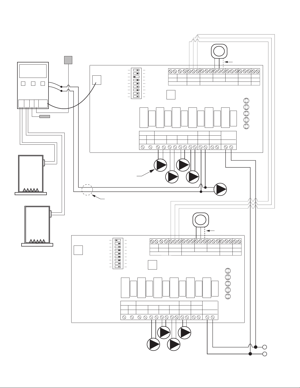
T
SWITCH SETTINGS
Master/Slave: Slave
Priority Zone: Off
Reset/Normal: Normal
SLAVE
PRIMARY SYSTEM
CIRCULATOR
(OPTIONAL)
DHW
CIRCULATOR
NOTE 1: Terminals C are for
optional 24V thermostat
COMMON connections.
See NOTE 1
See NOTE 1 See NOTE 1
3 Expandable Switching Relays Connected Together
13
120 VAC INPUT
TO: "TT" ON BOILER
H
N
SLAVE
120 VAC INPUT
MASTER
TT T
120 VAC INPUT
FOUR ZONE SWITCHING RELAY
120 VAC CIRCULATORS
ZC
INPUT
120 VAC
ZONE 1 ZONE 2 ZONE 3 ZONE 4
ZONE1
ZONE2
ZONE3
THERMOSTATS
SR 504-4
FUSE
6 AMP
FUSE
6 AMP
FUSE
6 AMP
FUSE
6 AMP
FUSE
6 AMP
X X
R W
R W
R W
R W
ISOLATED
END
SWITCH
THERMOSTATS (24 VAC)
PRIORITY
120 VAC
ZR
H H N H N H N H N H N H
ZONE4
ZONE 2
POWER
ZONE 1
ZONE 3
ZONE 4
LED
INDICATORS
ZONE 4
PRIORITY
OFF
ON
PRIORITY
24 VAC
COM
BOILER
SLAVE
ZONE
NOT
USED
TT T
FOUR ZONE SWITCHING RELAY
120 VAC CIRCULATORS
ZC
INPUT
120 VAC
ZONE 1 ZONE 2 ZONE 3 ZONE 4
ZONE1
ZONE2
ZONE3
THERMOSTATS
SR 504-4
FUSE
6 AMP
FUSE
6 AMP
FUSE
6 AMP
FUSE
6 AMP
FUSE
6 AMP
X X
R W
R W
R W
R W
ISOLATED
END
SWITCH
THERMOSTATS (24 VAC)
PRIORITY
120 VAC
ZR
H H N H N H N H N H N H
ZONE4
ZONE 2
POWER
ZONE 1
ZONE 3
ZONE 4
LED
INDICATORS
ZONE 4
PRIORITY
OFF
ON
PRIORITY
24 VAC
COM
INDIRECT
WATER HEATER
AQUASTAT OR
THERMOSTAT
ZONE
NOT
USED
JUMPER
JUMPER
PRIORITY
ON
PRIORITY
ON
TWO ZONE SWITCHING RELAY
CIRCULATORS
ZC
INPUT
120 VAC
ZONE 1
ZONE 2
PRIORITY
ZONE1
ZONE2
PRIORITY
SR 502-4
FUSE
6 AMP
FUSE
6 AMP
FUSE
6 AMP
X X
R W
R W
ISOLATED
END
SWITCH
THERMOSTATS
120 VAC
ZR
H H N H N H N H
ZONE 2
POWER
ZONE 1
LED
INDICATORS
ZONE 2
PRIORITY
OFF
ON
JUMPER
24 VAC
COM
120 VAC
PRIORITY
OFF
INDIRECT
WATER HEATER
AQUASTAT OR
THERMOSTAT
14
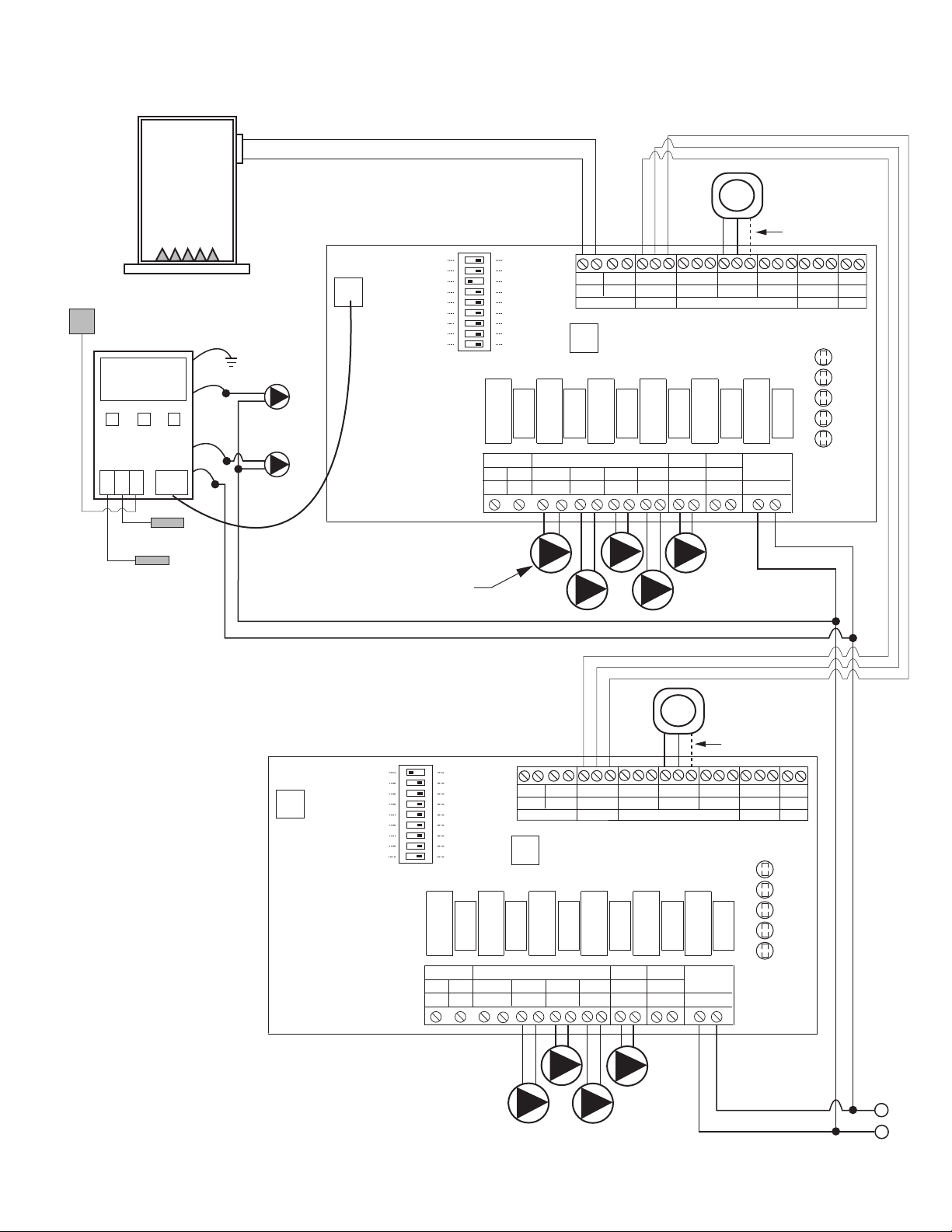
2 Indirect Water Heaters with Priority Connected to Standard Switching Relays
TO: "TT" ON BOILER
120 VAC INPUT
BOILER
INDIRECT
WATER HEATER
AQUASTAT OR
THERMOSTAT
TWO ZONE SWITCHING RELAY
CIRCULATORS
ZC
INPUT
120 VAC
ZONE 1
ZONE 2
PRIORITY
ZONE1
ZONE2
PRIORITY
SR 502-4
FUSE
6 AMP
FUSE
6 AMP
FUSE
6 AMP
X X
R W
R W
ISOLATED
END
SWITCH
THERMOSTATS
120 VAC
ZR
H H N H N H N H
ZONE 2
POWER
ZONE 1
LED
INDICATORS
ZONE 2
PRIORITY
OFF
ON
JUMPER
24 VAC
COM
DHW CIRCULATORS
PRIORITY
OFF
INDIRECT
WATER HEATER
AQUASTAT OR
THERMOSTAT
120 VAC INPUT
H
N
FOUR ZONE
EXPANDABLE
SWITCHING RELAY
POWER
CONTROLS
120 VAC CIRCULATORS
ZC
INPUT
120 VAC
ZONE 1
ZONE 2 ZONE 3 ZONE 4
ZONE1
ZONE2
ZONE3
THERMOSTATS
SR 504-EXP-4
FUSE
6 AMP
FUSE
6 AMP
FUSE
6 AMP
FUSE
6 AMP
FUSE
6 AMP
FUSE
6 AMP
NET
EXPANSIONMAIN PRIORITY
X X
X X
A B
C R W
C R W
C R W
C R W
C
1 2
END SWITCH THERMOSTATS (24 VAC)
PRIORITY
N/C
PRIMARY
120 VAC
ZR
H H N H N H N H N H N H N H N H
SLAVE
PRIORITY ON
RESET
PRIMARY PUMP ON
POST PURGE ON
PRIORITY PROTECT ON
PUMP EXERCISE ON
30 SEC/2 WK
MASTER
OFF
OFF
OFF
OFF
OFF
NORMAL
LOW LIMIT (ZC) ON OFF
4 MIN/24 HOUR
ZONE4 ZONE4
PRIORITY
ACCESSORY
PORT
ZONE 2
POWER
ZONE 1
ZONE 3
ZONE 4
LED
INDICATORS
T
SWITCH SETTINGS
Master/Slave: Master
Priority Zone: On
Reset/Normal: Normal
MASTER
PRIMARY SYSTEM
CIRCULATOR
(OPTIONAL)
ZONE
NOT
USED
FOUR ZONE
EXPANDABLE
SWITCHING RELAY
POWER
CONTROLS
120 VAC CIRCULATORS
ZC
INPUT
120 VAC
ZONE 1
ZONE 2 ZONE 3 ZONE 4
ZONE1
ZONE2
ZONE3
THERMOSTATS
SR 504-EXP-4
FUSE
6 AMP
FUSE
6 AMP
FUSE
6 AMP
FUSE
6 AMP
FUSE
6 AMP
FUSE
6 AMP
NET
EXPANSIONMAIN PRIORITY
X X
X X
A B
C R W
C R W
C R W
C R W
C
1 2
END SWITCH THERMOSTATS (24 VAC)
PRIORITY
N/C
PRIMARY
120 VAC
ZR
H H N H N H N H N H N H N H N H
SLAVE
PRIORITY ON
RESET
PRIMARY PUMP ON
POST PURGE ON
PRIORITY PROTECT ON
PUMP EXERCISE ON
30 SEC/2 WK
MASTER
OFF
OFF
OFF
OFF
OFF
NORMAL
LOW LIMIT (ZC) ON OFF
4 MIN/24 HOUR
ZONE4 ZONE4
PRIORITY
ACCESSORY
PORT
ZONE 2
POWER
ZONE 1
ZONE 3
ZONE 4
LED
INDICATORS
T
SWITCH SETTINGS
Master/Slave: Slave
Priority Zone: Off
Reset/Normal: Normal
SLAVE
NOTE 1: Terminals C are for
optional 24V thermostat
COMMON connections.
See NOTE 1
2 Indirect Water Heaters with Priority Connected to EXP Switching Relays
15
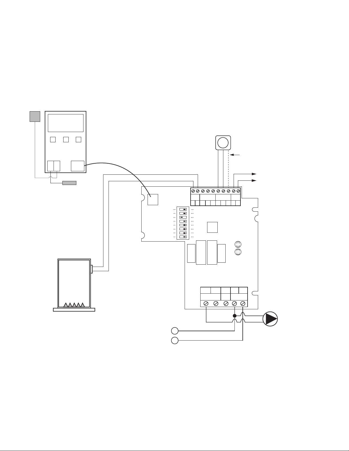
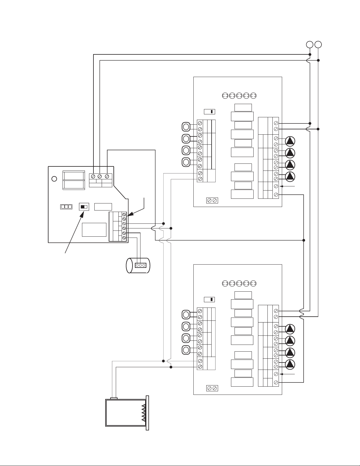
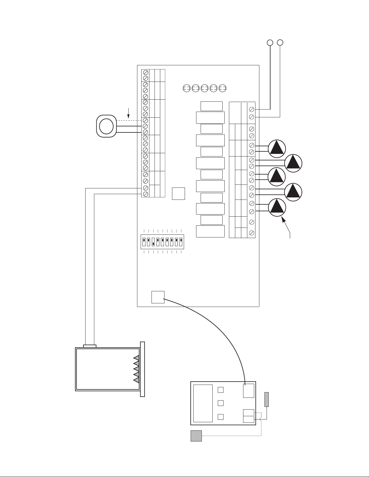
PC700 Boiler Reset Control Connected to SR501-EXP Switching Relay
ZONE
C
ONTROL
B
OIL
SEN
O
UT
SEN
BOILER SENSOR
OUTDOOR
SENSOR
PC700
SWITCH SETTINGS
Master/Slave: Master
Reset/Normal: Reset
SYSTEM
CIRCULATOR
TO: "TT" ON BOILER
POWER
ZONE 1
LED
INDICATORS
F
USE
6 AMP
F
USE
6 AMP
SR 501-EXP-4
POWER
CONTROLS
SLAVE
P
RIORITY ON
RESET
PRIMARY PUMP ON
POST PURGE ON
PRIORITY PROTECT ON
P
UMP EXERCISE ON
30 SEC/2 WK
MASTER
OFF
OFF
OFF
OFF
O
FF
NORMAL
4 MIN/24 HOUR
ACCESSORY
PORT
HN/O NH
120 VAC
CIRCULATOR
PRIMARY
OUTPUT
N/C
INPUT
120 VAC
END
SWITCH
RESET
OVERRIDE
THERMOSTATEXPANSION
X
W
R
X1A 2CB
24 VOLTS AC ONLY
C
SINGLE ZONE
EXPANDABLE SWITCHING RELAY
T
HERMOSTAT
T
120 VAC INPUT
H
N
BOILER
To: DHW Aquastat if PC700
Boiler Reset Temperature is
to be overridden during
DHW call.
NOTE 1: Terminals C are for
optional 24V thermostat
C
OMMON connections.
16
F
OUR ZONE SWITCHING RELAY
WITH OPTIONAL PRIORITY
ZONE 4
O
N
OFF
PRIORITY
120V RELAY
120 VOLT CIRCULATORS
ZC ZR
X
X
END
SWITCH
POWER
I
NPUT
120 VAC
INPUT
Z
ONE1
Z
ONE2
Z
ONE3
Z
ONE4
ZONE1 ZONE2 ZONE3 ZONE4
FUSE 1 AMP
24 VAC
POWER
SR 504
ZONE 2
P
OWER
Z
ONE 1
Z
ONE 3
ZONE 4
THERMOSTATS
BOILER
H
N
MASTER
EXISTING
ZONE
CONTROL
T
P
RIMARY
SYSTEM
CIRCULATOR
(Optional)
T
O: "TT" ON BOILER
J
UMPER
D
HW
H
EATER
CIRCULATOR
Note: If Zone Control comes on without a call for heat,
r
everse Reset Override input (1 & 2) wires on SR501-EXP.
ZONE
CONTROL
BOIL
SEN
OUT
SEN
B
OILER SENSOR
OUTDOOR
SENSOR
PC700
SWITCH SETTINGS
Master/Slave: Master
R
eset/Normal: Reset
P
OWER
Z
ONE 1
L
ED
INDICATORS
FUSE
6 AMP
FUSE
6 AMP
SR 501-EXP-4
P
OWER
C
ONTROLS
SLAVE
P
RIORITY ON
R
ESET
PRIMARY PUMP ON
P
OST PURGE ON
P
RIORITY PROTECT ON
P
UMP EXERCISE ON
30 SEC/2 WK
MASTER
O
FF
OFF
O
FF
O
FF
O
FF
N
ORMAL
4 MIN/24 HOUR
ACCESSORY
P
ORT
HN/O NH
120 VAC
CIRCULATOR
PRIMARY
OUTPUT
N/C
INPUT
120 VAC
E
ND
SWITCH
R
ESET
OVERRIDE
T
HERMOSTATEXPANSION
X
W
RX1A2CB
24 VOLTS AC ONLY
C
S
INGLE ZONE
E
XPANDABLE SWITCHING RELAY
INDIRECT
WATER HEATER
A
QUASTAT OR
T
HERMOSTAT
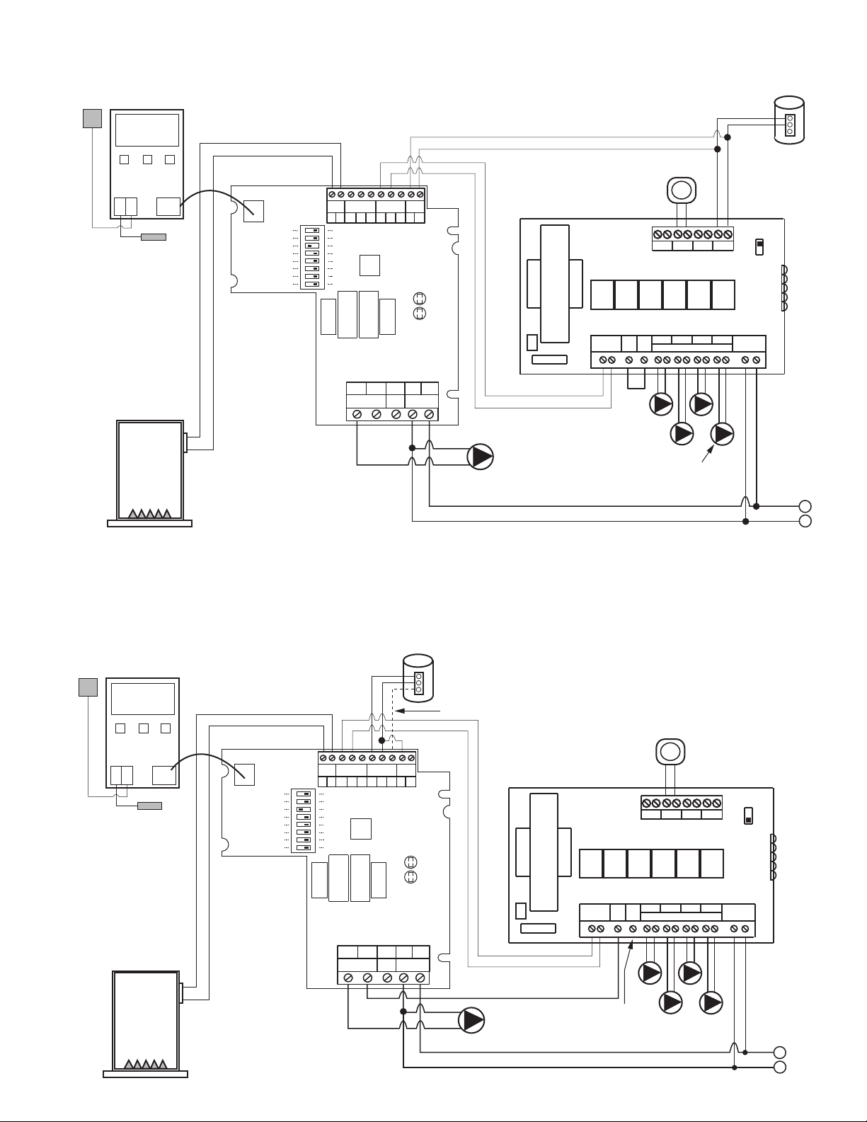
SR501-EXP and PC700 Boiler Reset Control Connected to an Existing Switching Relay
FOUR ZONE SWITCHING RELAY
WITH OPTIONAL PRIORITY
ZONE 4
ON
OFF
PRIORITY
120V RELAY
120 VOLT CIRCULATORS
ZC ZR
X X
END
SWITCH
POWER
INPUT
120 VAC
INPUT
ZONE1 ZONE2 ZONE3 ZONE4
ZONE1 ZONE2 ZONE3 ZONE4
FUSE 1 AMP
24 VAC
POWER
SR 504
ZONE 2
POWER
ZONE 1
ZONE 3
ZONE 4
THERMOSTATS
BOILER
H
N
EXISTING
ZONE
CONTROL
T
TO: "TT" ON BOILER
REMOVE
JUMPER
DHW
HEATER
CIRCULATOR
ZONE
CONTROL
BOIL
SEN
OUT
SEN
BOILER SENSOR
OUTDOOR
SENSOR
PC700
SLAVE
MASTER
SWITCH SETTINGS
Master/Slave: Master
Reset/Normal: Reset
POWER
ZONE 1
LED
INDICATORS
FUSE
6 AMP
FUSE
6 AMP
SR 501-EXP-4
P
OWER
CONTROLS
SLAVE
PRIORITY ON
RESET
PRIMARY PUMP ON
POST PURGE ON
PRIORITY PROTECT ON
PUMP EXERCISE ON
30 SEC/2 WK
MASTER
OFF
OFF
OFF
OFF
OFF
NORMAL
4 MIN/24 HOUR
ACCESSORY
PORT
HN/O NH
120 VAC
CIRCULATOR
PRIMARY
OUTPUT
N/C
INPUT
120 VAC
END
SWITCH
RESET
O
VERRIDE
THERMOSTATEXPANSION
XWRX1A 2CB
24 VOLTS AC ONLY
C
SINGLE ZONE
EXPANDABLE SWITCHING RELAY
INDIRECT
WATER HEATER
AQUASTAT OR
THERMOSTAT
NOTE 1: Terminals C are for
optional 24V thermostat
COMMON connections.
See NOTE 1
Connecting a DHW Heater to an Existing Heating Only Switching Relay
Using an SR501-EXP and PC700 Boiler Reset Control
17
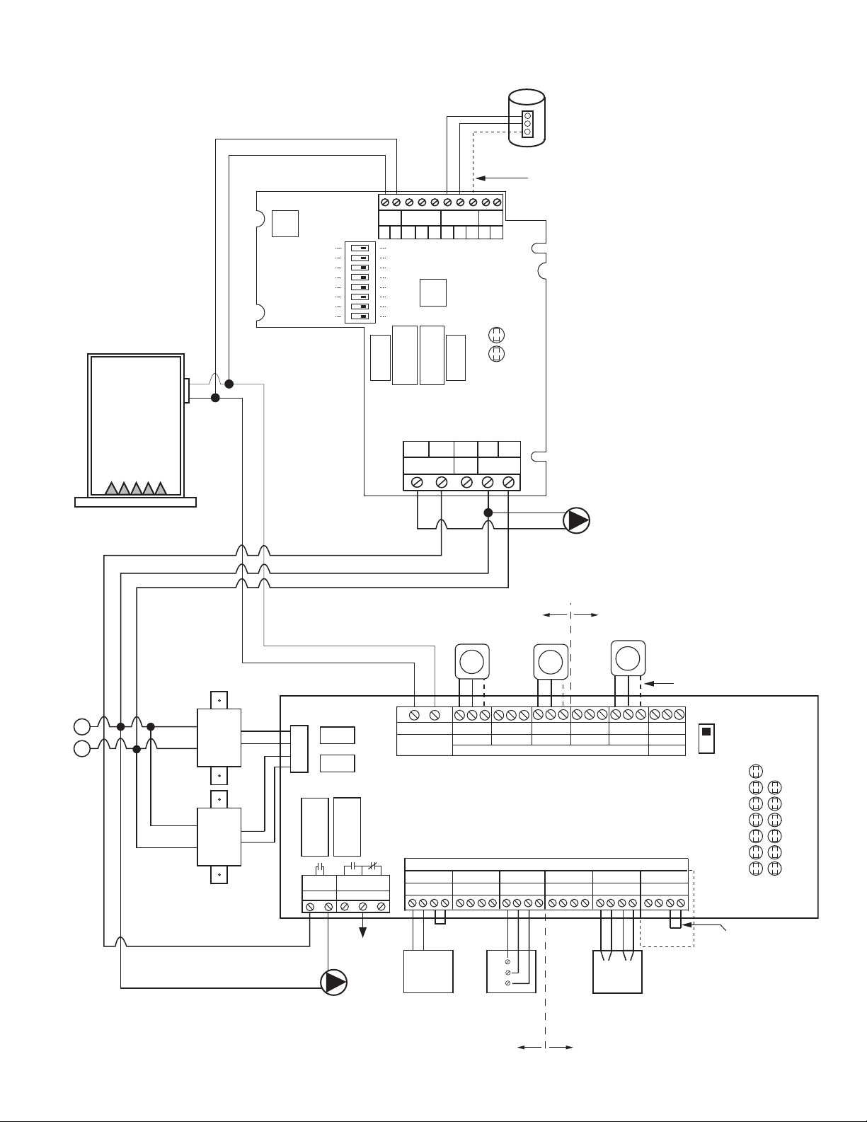
SR501-EXP and PC700 Boiler Reset Control Connected to an Existing Zone Valve Control
120 VAC
INPUT
BOILER
H
N
E
XISTING
Z
ONE
CONTROL
TO: "TT" ON BOILER
DHW HEATER
CIRCULATOR
N
ote: If Zone Control comes on without a call for heat,
reverse Reset Override input (1 & 2) wires on SR501-EXP.
ZONE
CONTROL
B
OIL
SEN
O
UT
SEN
BOILER SENSOR
OUTDOOR
SENSOR
PC700
2
4 VAC
P
OWER IN
Z
ONE 2 ZONE 3 ZONE 4
MODE
NORMAL RESET
FUSE
(3 AMP MAX)
Z
ONE 1
TT
TT TT TT
ZONE 4
PRIORITY
O
FF
ON
N/O COM
N/C
ZONE 4 RELAY
1234 1234
ZONE 1 ZONE 2
2
WIRE ZONE VALVE
(NO END SWITCH)
JUMPER
3
& 4
TACO
3
WIRE ZONE VALVE
1
2
3
1234
ZONE 3
MOTOR
END
SWITCH
4 WIRE ZONE VALVE
(
POWER OPEN,
SELF CLOSING)
T STAT 1
VALVE 1
T STAT 2
VALVE 2
T STAT 3
VALVE 3
T
STAT 4
VALVE 4
P
OWER
END
SWITCH
EXTRA
E
ND
S
WITCH
MAIN
24
V
AC
FACTORY
INSTALLED
TRANSFORMER
120 VAC
INPUT
W
HITE
BLACK
ZVC 404
FOUR ZONE ZONE VALVE CONTROL
WITH OPTIONAL PRIORITY
1234
ZONE 4
PRIORITY
ZONE
J
UMPER
3 & 4
SEE NOTE
THERMOSTATS
T
T
T
Note: When a circulator is used on the
p
riority zone instead of a zone valve,
jumper 3 and 4 of the priority zone.
ZONE VALVE SYSTEM
CIRCULATOR
I
NDIRECT
WATER HEATER
AQUASTAT OR
THERMOSTAT
MASTER
P
RIMARY SYSTEM
C
IRCULATOR
(Optional)
SWITCH SETTINGS
M
aster/Slave: Master
Reset/Normal: Reset
POWER
ZONE 1
LED
I
NDICATORS
FUSE
6
AMP
FUSE
6
AMP
SR 501-EXP-4
P
OWER
C
ONTROLS
SLAVE
PRIORITY ON
R
ESET
P
RIMARY PUMP ON
POST PURGE ON
P
RIORITY PROTECT ON
P
UMP EXERCISE ON
3
0 SEC/2 WK
MASTER
OFF
O
FF
OFF
O
FF
O
FF
N
ORMAL
4
MIN/24 HOUR
A
CCESSORY
P
ORT
HN/O NH
1
20 VAC
CIRCULATOR
PRIMARY
O
UTPUT
N/C
INPUT
120 VAC
E
ND
SWITCH
R
ESET
OVERRIDE
T
HERMOSTATEXPANSION
X
W
RX1A2CB
24 VOLTS AC ONLY
C
SINGLE ZONE
EXPANDABLE SWITCHING RELAY
120 VAC
INPUT
BOILER
H
N
EXISTING
ZONE
CONTROL
DHW HEATER
CIRCULATOR
TO: "TT" ON BOILER
ZONE
CONTROL
BOIL
SEN
OUT
SEN
BOILER SENSOR
OUTDOOR
SENSOR
PC700
24 VAC
P
OWER IN
ZONE 2 ZONE 3 ZONE 4
MODE
N
ORMAL RESET
FUSE
(3 AMP MAX)
ZONE 1
TT
TT TT TT
ZONE 4
PRIORITY
O
FF
O
N
N
/O COM
N/C
Z
ONE 4 RELAY
1234 1234
ZONE 1 ZONE 2
2 WIRE ZONE VALVE
(NO END SWITCH)
JUMPER
3 & 4
TACO
3 WIRE ZONE VALVE
1
2
3
1234
ZONE 3
MOTOR
END
SWITCH
4 WIRE ZONE VALVE
(POWER OPEN,
SELF CLOSING)
T STAT 1
VALVE 1
T STAT 2
VALVE 2
T STAT 3
VALVE 3
T STAT 4
VALVE 4
POWER
END
SWITCH
E
XTRA
E
ND
S
WITCH
MAIN
24
V
AC
FACTORY
INSTALLED
TRANSFORMER
120 VAC
I
NPUT
WHITE
BLACK
ZVC 404
FOUR ZONE ZONE VALVE CONTROL
WITH OPTIONAL PRIORITY
1234
ZONE 4
PRIORITY
ZONE
JUMPER
3 & 4
SEE NOTE
THERMOSTATS
T
T
T
Note: When a circulator is used on the
priority zone instead of a zone valve,
jumper 3 and 4 of the priority zone.
ZONE VALVE SYSTEM
CIRCULATOR
SLAVE
MASTER
SWITCH SETTINGS
Master/Slave: Master
Reset/Normal: Reset
POWER
ZONE 1
LED
INDICATORS
FUSE
6 AMP
FUSE
6 AMP
SR 501-EXP-4
POWER
C
ONTROLS
SLAVE
PRIORITY ON
RESET
PRIMARY PUMP ON
POST PURGE ON
PRIORITY PROTECT ON
PUMP EXERCISE ON
30 SEC/2 WK
MASTER
OFF
OFF
OFF
OFF
OFF
NORMAL
4 MIN/24 HOUR
ACCESSORY
PORT
HN/O NH
120 VAC
CIRCULATOR
PRIMARY
OUTPUT
N/C
INPUT
120 VAC
END
SWITCH
RESET
OVERRIDE
T
HERMOSTATEXPANSION
XWRX1A 2CB
24 VOLTS AC ONLY
C
SINGLE ZONE
EXPANDABLE SWITCHING RELAY
INDIRECT
WATER HEATER
AQUASTAT OR
THERMOSTAT
NOTE 1: Terminals C are for
optional 24V thermostat
COMMON connections.
See NOTE 1
18
Connecting a DHW Heater to an Existing Heating Only Zone Valve Control
Using an SR501-EXP and PC700 Boiler Reset Control
SR501-EXP and PC702 Boiler Reset Control Connected to an Existing Switching Relay
F
OUR ZONE SWITCHING RELAY
WITH OPTIONAL PRIORITY
ZONE 4
ON
OFF
PRIORITY
120V RELAY
120 VOLT CIRCULATORS
ZC ZR
X X
END
SWITCH
P
OWER
INPUT
120 VAC
INPUT
ZONE1 ZONE2 ZONE3 ZONE4
ZONE1 ZONE2 ZONE3 ZONE4
FUSE 1 AMP
24 VAC
POWER
SR 504
Z
ONE 2
POWER
ZONE 1
Z
ONE 3
Z
ONE 4
THERMOSTATS
H
N
MASTER
EXISTING
ZONE
CONTROL
T
P
RIMARY
S
YSTEM
C
IRCULATOR
(Optional)
JUMPER
D
HW
HEATER
CIRCULATOR
N
ote: If Zone Control comes on without a call for heat,
reverse Reset Override input (1 & 2) wires on SR501-EXP.
SWITCH SETTINGS
Master/Slave: Master
R
eset/Normal: Reset
POWER
Z
ONE 1
LED
INDICATORS
FUSE
6 AMP
FUSE
6 AMP
SR 501-EXP-4
POWER
CONTROLS
S
LAVE
P
RIORITY ON
R
ESET
P
RIMARY PUMP ON
P
OST PURGE ON
P
RIORITY PROTECT ON
P
UMP EXERCISE ON
30 SEC/2 WK
M
ASTER
O
FF
O
FF
O
FF
O
FF
O
FF
N
ORMAL
4 MIN/24 HOUR
A
CCESSORY
PORT
HN/O NH
120 VAC
CIRCULATOR
PRIMARY
OUTPUT
N/C
INPUT
120 VAC
END
SWITCH
RESET
OVERRIDE
THERMOSTATEXPANSION
XWRX1A 2CB
24 VOLTS AC ONLY
C
SINGLE ZONE
EXPANDABLE SWITCHING RELAY
INDIRECT
WATER HEATER
AQUASTAT OR
THERMOSTAT
ZONE
CONTROL
B
OIL
SEN
O
UT
SEN
BOILER SENSOR
OUTDOOR
SENSOR
PC702
STAGE1STAGE
2
B
OILER
#2
BOILER
#1
DHW
DEMAND
WIRING NEEDED ONLY IF
PRIORITY ZONE IS DHW
FOUR ZONE SWITCHING RELAY
WITH OPTIONAL PRIORITY
ZONE 4
ON
OFF
PRIORITY
120V RELAY
120 VOLT CIRCULATORS
ZC ZR
X X
END
SWITCH
POWER
INPUT
120 VAC
INPUT
ZONE1 ZONE2 ZONE3 ZONE4
ZONE1 ZONE2 ZONE3 ZONE4
FUSE 1 AMP
24 VAC
POWER
SR 504
ZONE 2
POWER
ZONE 1
ZONE 3
ZONE 4
THERMOSTATS
BOILER
H
N
EXISTING
ZONE
CONTROL
T
TO: "TT" ON BOILER
SLAVE
MASTER
SWITCH SETTINGS
Master/Slave: Master
Reset/Normal: Reset
POWER
ZONE 1
LED
INDICATORS
FUSE
6 AMP
FUSE
6 AMP
SR 501-EXP-4
POWER
C
ONTROLS
SLAVE
PRIORITY ON
RESET
PRIMARY PUMP ON
POST PURGE ON
PRIORITY PROTECT ON
PUMP EXERCISE ON
30 SEC/2 WK
MASTER
OFF
OFF
OFF
OFF
OFF
NORMAL
4 MIN/24 HOUR
ACCESSORY
PORT
HN/O NH
120 VAC
CIRCULATOR
PRIMARY
OUTPUT
N/C
INPUT
120 VAC
END
SWITCH
RESET
OVERRIDE
THERMOSTATEXPANSION
XWRX1A 2CB
24 VOLTS AC ONLY
C
SINGLE ZONE
EXPANDABLE SWITCHING RELAY
INDIRECT
WATER HEATER
AQUASTAT OR
THERMOSTAT
ZONE
CONTROL
BOIL
SEN
OUT
SEN
BOILER SENSOR
OUTDOOR
SENSOR
PC705-2
SUP
SEN
SUPPLY SENSOR
INJECTION
CIRCULATOR
SYSTEM
CIRCULATOR
BLACK
BLUE
RED
GREEN/GROUND
(SEE NOTE B
ON PAGE 22)
PRIMARY
SYSTEM
CIRCULATOR
(Optional)
Note: If Zone Control comes on without a call for heat,
reverse Reset Override input (1 & 2) wires on SR501-EXP.
JUMPER
SR501-EXP and PC705 Variable Speed Pump Injection Control Connected
to an Existing Switching Relay
19
ZONE
CONTROL
BOIL
SEN
OUT
SEN
BOILER SENSOR
OUTDOOR
SENSOR
PC700
BOILER
120 VAC INPUT
SWITCH SETTINGS
Master/Slave: Master
Priority Zone: On or Off
Reset/Normal: Reset
FOUR ZONE
EXPANDABLE
SWITCHING RELAY
POWER
CONTROLS
120 VAC CIRCULATORS
ZC
INPUT
120 VAC
ZONE 1
ZONE 2 ZONE 3 ZONE 4
ZONE1
ZONE2
ZONE3
THERMOSTATS
SR 504-EXP-4
FUSE
6 AMP
FUSE
6 AMP
FUSE
6 AMP
FUSE
6 AMP
FUSE
6 AMP
FUSE
6 AMP
NET
EXPANSIONMAIN PRIORITY
X X
X X
A B
C R W
C R W
C R W
C R W
C
1 2
END SWITCH THERMOSTATS (24 VAC)
PRIORITY
N/C
PRIMARY
120 VAC
ZR
H H N H N H N H N H N H N H N H
SLAVE
PRIORITY ON
RESET
PRIMARY PUMP ON
POST PURGE ON
PRIORITY PROTECT ON
PUMP EXERCISE ON
30 SEC/2 WK
MASTER
OFF
OFF
OFF
OFF
OFF
NORMAL
LOW LIMIT (ZC) ON OFF
4 MIN/24 HOUR
ZONE4 ZONE4
PRIORITY
ACCESSORY
PORT
ZONE 2
POWER
ZONE 1
ZONE 3
ZONE 4
LED
INDICATORS
T
H
N
NOTE 1: Terminals C are for
optional 24V thermostat
COMMON connections.
PRIMARY SYSTEM
CIRCULATOR
(OPTIONAL)
20
PC700 Boiler Reset Control Connected to EXP Switching Relay
ZONE
CONTROL
BOIL
SEN
OUT
SEN
BOILER SENSOR
OUTDOOR
SENSOR
PC702
STAGE
1
STAGE
2
BOILER
#2
BOILER
#1
DHW
DEMAND
WIRING NEEDED ONLY IF
PRIORITY ZONE IS DHW
PRIMARY SYSTEM
CIRCULATOR
(OPTIONAL)
120 VAC INPUT
SWITCH SETTINGS
Master/Slave: Master
Priority Zone: On or Off
Reset/Normal: Reset
FOUR ZONE
EXPANDABLE
SWITCHING RELAY
POWER
CONTROLS
120 VAC CIRCULATORS
ZC
INPUT
120 VAC
ZONE 1
ZONE 2 ZONE 3 ZONE 4
ZONE1
ZONE2
ZONE3
THERMOSTATS
SR 504-EXP-4
FUSE
6 AMP
FUSE
6 AMP
FUSE
6 AMP
FUSE
6 AMP
FUSE
6 AMP
FUSE
6 AMP
NET
EXPANSIONMAIN PRIORITY
X X
X X
A B
C R W
C R W
C R W
C R W
C
1 2
END SWITCH THERMOSTATS (24 VAC)
PRIORITY
N/C
PRIMARY
120 VAC
ZR
H H N H N H N H N H N H N H N H
SLAVE
PRIORITY ON
RESET
PRIMARY PUMP ON
POST PURGE ON
PRIORITY PROTECT ON
PUMP EXERCISE ON
30 SEC/2 WK
MASTER
OFF
OFF
OFF
OFF
OFF
NORMAL
LOW LIMIT (ZC) ON OFF
4 MIN/24 HOUR
ZONE4 ZONE4
PRIORITY
ACCESSORY
PORT
ZONE 2
POWER
ZONE 1
ZONE 3
ZONE 4
LED
INDICATORS
T
H
N
NOTE 1: Terminals C are for
optional 24V thermostat
COMMON connections.
PC702 2–Stage Boiler Reset Control Connected to EXP Switching Relay
21
TO: "TT" ON BOILER
BOILER
ZONE
CONTROL
BOIL
SEN
OUT
SEN
BOILER SENSOR
OUTDOOR
SENSOR
PC705-2
SUP
SEN
SUPPLY SENSOR
INJECTION
CIRCULATOR
SYSTEM
AND/OR BOILER
CIRCULATOR
BLACK
BLUE
RED
GREEN/GROUND
(SEE NOTE B)
NOTE A: WHEN SYSTEM CIRCULATOR IS CONNECTED TO PRIMARY CIRCULATOR TERMINAL ON SWITCHING RELAY,
THE PRIMARY PUMP DIP SWITCH SETS OPERATION OF THIS OUTPUT.
NOTE B: WHEN SYSTEM CIRCULATOR IS CONNECTED TO RED WIRE ON PC705-2, THE CIRCULATOR WILL OPERATE ONLY WHEN THERMOSTAT CALLS FOR HEAT
AND THE OUTDOOR TEMPERATURE IS BELOW THE WARM WEATHER SHUT DOWN (WWSD) TEMPERATURE. THE WWSD CAN BE ADJUSTED OR TURNED
OFF SO THAT THE CIRCULATOR IS NOT AFFECTED BY OUTDOOR TEMPERATURE.
SYSTEM
AND/OR BOILER
CIRCULATOR
(SEE NOTE A)
120 VAC INPUT
SWITCH SETTINGS
Master/Slave: Master
Priority Zone: On or Off
Reset/Normal: Reset
FOUR ZONE
EXPANDABLE
SWITCHING RELAY
POWER
CONTROLS
120 VAC CIRCULATORS
ZC
INPUT
120 VAC
ZONE 1
ZONE 2 ZONE 3 ZONE 4
ZONE1
ZONE2
ZONE3
THERMOSTATS
SR 504-EXP-4
FUSE
6 AMP
FUSE
6 AMP
FUSE
6 AMP
FUSE
6 AMP
FUSE
6 AMP
FUSE
6 AMP
NET
EXPANSIONMAIN PRIORITY
X X
X X
A B
C R W
C R W
C R W
C R W
C
1 2
END SWITCH THERMOSTATS (24 VAC)
PRIORITY
N/C
PRIMARY
120 VAC
ZR
H H N H N H N H N H N H N H N H
SLAVE
PRIORITY ON
RESET
PRIMARY PUMP ON
POST PURGE ON
PRIORITY PROTECT ON
PUMP EXERCISE ON
30 SEC/2 WK
MASTER
OFF
OFF
OFF
OFF
OFF
NORMAL
LOW LIMIT (ZC) ON OFF
4 MIN/24 HOUR
ZONE4 ZONE4
PRIORITY
ACCESSORY
PORT
ZONE 2
POWER
ZONE 1
ZONE 3
ZONE 4
LED
INDICATORS
T
H
N
NOTE 1: Terminals C are for
optional 24V thermostat
COMMON connections.
22
PC705 Variable Speed Pump Injection Control Connected to EXP Switching Relay
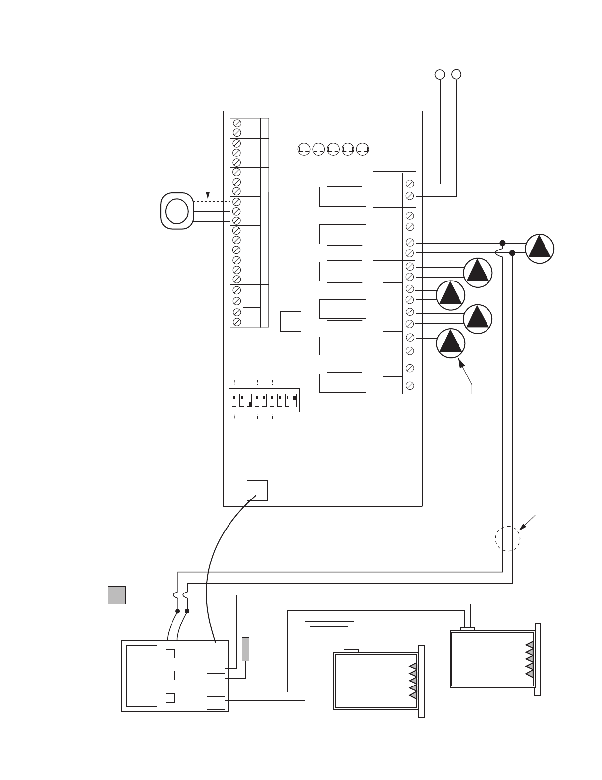
PC700 Boiler Reset Control Connected to 2 EXP Switching Relays
Z
ONE
CONTROL
B
OIL
SEN
O
UT
SEN
BOILER SENSOR
O
UTDOOR
SENSOR
PC700
BOILER
120 VAC INPUT
SWITCH SETTINGS
Master/Slave: Master
Priority Zone: On or Off
Reset/Normal: Reset
FOUR ZONE
EXPANDABLE
SWITCHING RELAY
P
OWER
CONTROLS
1
20 VAC CIRCULATORS
Z
C
INPUT
1
20 VAC
ZONE 1 ZONE 2 ZONE 3 ZONE 4
ZONE1 ZONE2 ZONE3
T
HERMOSTATS
SR 504-EXP-4
F
USE
6 AMP
FUSE
6 AMP
F
USE
6 AMP
F
USE
6 AMP
FUSE
6 AMP
FUSE
6 AMP
NET
EXPANSIONMAIN PRIORITY
X
X
X
X
A
B
C
RW
C
RW
C
RW
C
RW
C
1
2
END SWITCH THERMOSTATS (24 VAC)
PRIORITY
N/C
P
RIMARY
120 VAC
Z
R
HHNHNHNHNHNHNH NH
SLAVE
PRIORITY ON
R
ESET
PRIMARY PUMP ON
POST PURGE ON
PRIORITY PROTECT ON
PUMP EXERCISE ON
30 SEC/2 WK
MASTER
OFF
OFF
OFF
OFF
OFF
NORMAL
LOW LIMIT (ZC) ON OFF
4 MIN/24 HOUR
ZONE4 ZONE4
P
RIORITY
ACCESSORY
P
ORT
ZONE 2
POWER
ZONE 1
ZONE 3
ZONE 4
LED
INDICATORS
T
P
RIMARY SYSTEM
CIRCULATOR
(
OPTIONAL)
120 VAC INPUT
SWITCH SETTINGS
Master/Slave: Slave
Priority Zone: Off
Reset/Normal: Normal
FOUR ZONE
EXPANDABLE
SWITCHING RELAY
POWER
CONTROLS
120 VAC CIRCULATORS
ZC
INPUT
120 VAC
ZONE 1 ZONE 2 ZONE 3 ZONE 4
ZONE1 ZONE2 ZONE3
THERMOSTATS
SR 504-EXP-4
FUSE
6 AMP
FUSE
6 AMP
FUSE
6 AMP
FUSE
6 AMP
FUSE
6 AMP
FUSE
6 AMP
NET
EXPANSIONMAIN PRIORITY
XX
XXABCRW
CRW
CRW
CRWC12
END SWITCH THERMOSTATS (24 VAC)
PRIORITY
N/C
PRIMARY
120 VAC
ZR
HHNHNHNHNHNHNH NH
SLAVE
PRIORITY ON
RESET
PRIMARY PUMP ON
POST PURGE ON
PRIORITY PROTECT ON
PUMP EXERCISE ON
30 SEC/2 WK
MASTER
OFF
OFF
OFF
OFF
OFF
NORMAL
LOW LIMIT (ZC) ON OFF
4 MIN/24 HOUR
ZONE4 ZONE4
PRIORITY
ACCESSORY
PORT
ZONE 2
POWER
ZONE 1
ZONE 3
ZONE 4
LED
INDICATORS
T
H
N
MASTER
SLAVE
See NOTE 1
NOTE 1: Terminals C are for
optional 24V thermostat
COMMON connections.
See NOTE 1
23
PC702 2–Stage Boiler Reset Control Connected to 2 EXP Switching Relays
120 VAC INPUT
SWITCH SETTINGS
Master/Slave: Master
Priority Zone: On or Off
Reset/Normal: Reset
FOUR ZONE
EXPANDABLE
SWITCHING RELAY
POWER
CONTROLS
120 VAC CIRCULATORS
ZC
INPUT
120 VAC
ZONE 1 ZONE 2 ZONE 3 ZONE 4
Z
ONE1
Z
ONE2
Z
ONE3
THERMOSTATS
SR 504-EXP-4
F
USE
6 AMP
FUSE
6 AMP
F
USE
6 AMP
F
USE
6 AMP
FUSE
6 AMP
FUSE
6 AMP
NET
EXPANSIONMAIN PRIORITY
X
X
X
X
A
B
C
RW
C
RW
C
RW
C
RW
C
1
2
END SWITCH THERMOSTATS (24 VAC)
P
RIORITY
N
/C
PRIMARY
120 VAC
ZR
H
HNHNHNHNHNHNH NH
S
LAVE
PRIORITY ON
RESET
P
RIMARY PUMP ON
POST PURGE ON
PRIORITY PROTECT ON
P
UMP EXERCISE ON
30 SEC/2 WK
M
ASTER
OFF
O
FF
OFF
OFF
O
FF
NORMAL
LOW LIMIT (ZC) ON OFF
4 MIN/24 HOUR
Z
ONE4 ZONE4
PRIORITY
ACCESSORY
PORT
ZONE 2
POWER
ZONE 1
ZONE 3
ZONE 4
LED
INDICATORS
T
120 VAC INPUT
SWITCH SETTINGS
Master/Slave: Slave
Priority Zone: Off
Reset/Normal: Normal
FOUR ZONE
EXPANDABLE
SWITCHING RELAY
POWER
CONTROLS
120 VAC CIRCULATORS
ZC
INPUT
120 VAC
ZONE 1 ZONE 2 ZONE 3 ZONE 4
ZONE1 ZONE2 ZONE3
THERMOSTATS
SR 504-EXP-4
FUSE
6 AMP
FUSE
6 AMP
FUSE
6 AMP
FUSE
6 AMP
FUSE
6 AMP
FUSE
6 AMP
NET
EXPANSIONMAIN PRIORITY
XX XX ABCRWCRWCRWCRWC 12
END SWITCH THERMOSTATS (24 VAC)
PRIORITY
N/C
PRIMARY
120 VAC
ZR
HHNHNHNHNHNHNH NH
SLAVE
PRIORITY ON
RESET
PRIMARY PUMP ON
POST PURGE ON
PRIORITY PROTECT ON
PUMP EXERCISE ON
30 SEC/2 WK
MASTER
OFF
OFF
OFF
OFF
OFF
NORMAL
LOW LIMIT (ZC) ON OFF
4 MIN/24 HOUR
ZONE4 ZONE4
PRIORITY
ACCESSORY
PORT
ZONE 2
POWER
ZONE 1
ZONE 3
ZONE 4
LED
INDICATORS
T
H
N
MASTER
SLAVE
ZONE
CONTROL
BOIL
SEN
OUT
SEN
B
OILER SENSOR
O
UTDOOR
SENSOR
PC702
STAGE1STAGE
2
BOILER
#2
BOILER
#1
DHW
D
EMAND
WIRING NEEDED ONLY IF
PRIORITY ZONE IS DHW
P
RIMARY SYSTEM
CIRCULATOR
(OPTIONAL)
See NOTE 1
NOTE 1: Terminals C are for
optional 24V thermostat
COMMON connections.
See NOTE 1
24
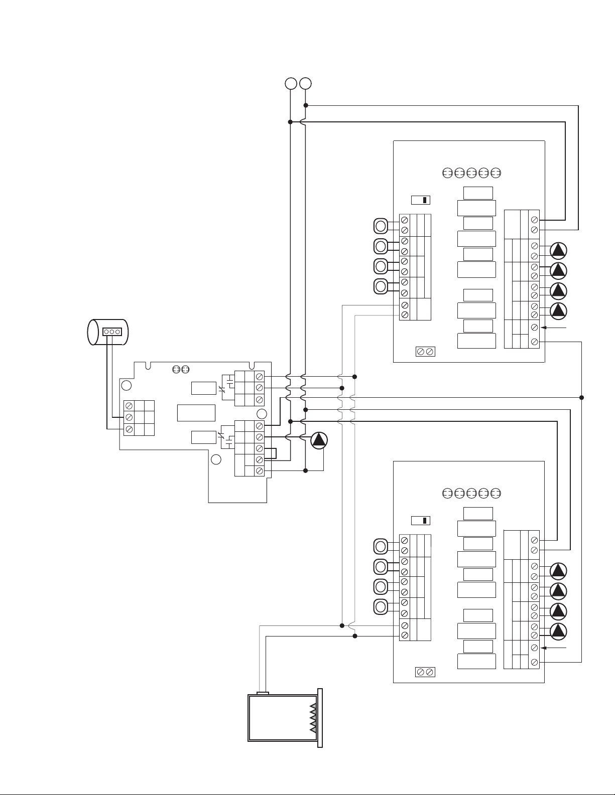
PC705 Variable Speed Pump Injection Control Connected to 2 EXP Switching Relays
120 VAC INPUT
SWITCH SETTINGS
M
aster/Slave: Master
Priority Zone: On or Off
Reset/Normal: Reset
FOUR ZONE
EXPANDABLE
SWITCHING RELAY
P
OWER
CONTROLS
120 VAC CIRCULATORS
ZC
INPUT
120 VAC
ZONE 1 ZONE 2 ZONE 3 ZONE 4
ZONE1 ZONE2 ZONE3
THERMOSTATS
SR 504-EXP-4
FUSE
6 AMP
F
USE
6 AMP
FUSE
6 AMP
FUSE
6 AMP
F
USE
6 AMP
F
USE
6 AMP
NET
EXPANSIONMAIN PRIORITY
X
X
X
X
A
B
C
RW
C
RW
C
RW
C
RW
C
1
2
END SWITCH THERMOSTATS (24 VAC)
PRIORITY
N/C
P
RIMARY
120 VAC
ZR
HHNHNHNHNHNHNH NH
SLAVE
PRIORITY ON
RESET
PRIMARY PUMP ON
POST PURGE ON
PRIORITY PROTECT ON
PUMP EXERCISE ON
30 SEC/2 WK
MASTER
OFF
OFF
OFF
OFF
OFF
NORMAL
LOW LIMIT (ZC) ON OFF
4 MIN/24 HOUR
ZONE4 ZONE4
PRIORITY
ACCESSORY
P
ORT
ZONE 2
POWER
ZONE 1
ZONE 3
ZONE 4
LED
INDICATORS
T
120 VAC INPUT
SWITCH SETTINGS
Master/Slave: Slave
Priority Zone: Off
Reset/Normal: Normal
FOUR ZONE
EXPANDABLE
SWITCHING RELAY
POWER
C
ONTROLS
120 VAC CIRCULATORS
ZC
INPUT
120 VAC
ZONE 1 ZONE 2 ZONE 3 ZONE 4
ZONE1 ZONE2 ZONE3
THERMOSTATS
SR 504-EXP-4
FUSE
6 AMP
FUSE
6 AMP
FUSE
6 AMP
FUSE
6 AMP
FUSE
6 AMP
FUSE
6 AMP
NET
EXPANSIONMAIN PRIORITY
XX
XXABCRW
CRW
CRW
CRWC12
END SWITCH THERMOSTATS (24 VAC)
PRIORITY
N/C
PRIMARY
120 VAC
ZR
HHNHNHNHNHNHNH NH
SLAVE
P
RIORITY ON
RESET
PRIMARY PUMP ON
POST PURGE ON
PRIORITY PROTECT ON
PUMP EXERCISE ON
30 SEC/2 WK
MASTER
OFF
OFF
OFF
OFF
OFF
NORMAL
LOW LIMIT (ZC) ON OFF
4 MIN/24 HOUR
ZONE4 ZONE4
PRIORITY
ACCESSORY
PORT
ZONE 2
POWER
ZONE 1
ZONE 3
ZONE 4
LED
INDICATORS
T
H
N
MASTER
SLAVE
T
O: "TT" ON BOILER
BOILER
ZONE
C
ONTROL
BOIL
S
EN
OUT
S
EN
BOILER SENSOR
OUTDOOR
SENSOR
PC705-2
SUP
S
EN
SUPPLY SENSOR
INJECTION
CIRCULATOR
SYSTEM
CIRCULATOR
B
LACK
BLUE
RED
G
REEN/GROUND
(
SEE NOTE B
ON PAGE 22)
(SEE NOTE A
O
N PAGE 22)
PRIMARY SYSTEM
CIRCULATOR
(OPTIONAL)
See NOTE 1
NOTE 1: Terminals C are for
optional 24V thermostat
COMMON connections.
See NOTE 1
25
PC700 and PC705 Controls Connected to 2 EXP Switching Relays
120 VAC INPUT
SWITCH SETTINGS
M
aster/Slave: Master
Priority Zone: On or Off
Reset/Normal: Reset
FOUR ZONE
EXPANDABLE
SWITCHING RELAY
POWER
CONTROLS
1
20 VAC CIRCULATORS
Z
C
I
NPUT
120 VAC
ZONE 1 ZONE 2 ZONE 3 ZONE 4
ZONE1 ZONE2 ZONE3
THERMOSTATS
SR 504-EXP-4
FUSE
6 AMP
FUSE
6 AMP
FUSE
6 AMP
FUSE
6 AMP
FUSE
6 AMP
FUSE
6 AMP
NET
EXPANSIONMAIN PRIORITY
XX
XXABCRW
CRW
CRW
CRWC12
END SWITCH THERMOSTATS (24 VAC)
PRIORITY
N/C
PRIMARY
120 VAC
ZR
HHNHNHNHNHNHNH NH
SLAVE
PRIORITY ON
RESET
PRIMARY PUMP ON
POST PURGE ON
PRIORITY PROTECT ON
PUMP EXERCISE ON
30 SEC/2 WK
MASTER
OFF
OFF
OFF
OFF
OFF
NORMAL
LOW LIMIT (ZC) ON OFF
4 MIN/24 HOUR
ZONE4 ZONE4
PRIORITY
A
CCESSORY
PORT
ZONE 2
P
OWER
ZONE 1
ZONE 3
ZONE 4
LED
INDICATORS
T
120 VAC INPUT
SWITCH SETTINGS
Master/Slave: Slave
Priority Zone: Off
Reset/Normal: Reset
FOUR ZONE
EXPANDABLE
SWITCHING RELAY
POWER
CONTROLS
120 VAC CIRCULATORS
ZC
INPUT
120 VAC
ZONE 1 ZONE 2 ZONE 3 ZONE 4
ZONE1 ZONE2 ZONE3
THERMOSTATS
SR 504-EXP-4
FUSE
6 AMP
FUSE
6 AMP
FUSE
6 AMP
FUSE
6 AMP
FUSE
6 AMP
FUSE
6 AMP
NET
EXPANSIONMAIN PRIORITY
XX
XX
AB
CRW
CRW
CRW
CRWC12
END SWITCH THERMOSTATS (24 VAC)
PRIORITY
N/C
PRIMARY
120 VAC
ZR
HHNHNHNHNHNHNH NH
SLAVE
PRIORITY ON
RESET
PRIMARY PUMP ON
POST PURGE ON
PRIORITY PROTECT ON
PUMP EXERCISE ON
30 SEC/2 WK
MASTER
O
FF
OFF
OFF
OFF
OFF
NORMAL
LOW LIMIT (ZC) ON OFF
4 MIN/24 HOUR
ZONE4 ZONE4
PRIORITY
ACCESSORY
PORT
ZONE 2
POWER
ZONE 1
ZONE 3
ZONE 4
LED
INDICATORS
T
H
N
MASTER
SLAVE
T
O: "TT" ON BOILER
BOILER
ZONE
CONTROL
BOIL
SEN
OUT
SEN
BOILER SENSOR
OUTDOOR
SENSOR
PC705-2
SUP
SEN
SUPPLY SENSOR
INJECTION
CIRCULATOR
SYSTEM
CIRCULATOR
BLACK
BLUE
RED
GREEN/GROUND
(SEE NOTE B
ON PAGE 22)
ZONE
CONTROL
BOIL
SEN
OUT
SEN
B
OILER SENSOR
O
UTDOOR
S
ENSOR
PC700
(SEE NOTE A
ON PAGE 22)
PRIMARY SYSTEM
CIRCULATOR
(OPTIONAL)
S
ee NOTE 1
NOTE 1: Terminals C are for
optional 24V thermostat
COMMON connections.
See NOTE 1
26
1
20 VAC INPUT
SWITCH SETTINGS
Master/Slave: Master
Priority Zone: On or Off
Reset/Normal: Reset
FOUR ZONE
EXPANDABLE
SWITCHING RELAY
P
OWER
C
ONTROLS
120 VAC CIRCULATORS
Z
C
INPUT
120 VAC
ZONE 1 ZONE 2 ZONE 3 ZONE 4
ZONE1 ZONE2 ZONE3
THERMOSTATS
SR 504-EXP-4
F
USE
6 AMP
FUSE
6 AMP
F
USE
6 AMP
F
USE
6 AMP
FUSE
6 AMP
FUSE
6 AMP
NET
EXPANSIONMAIN PRIORITY
XX
XXABCRW
CRW
CRW
CRWC12
END SWITCH THERMOSTATS (24 VAC)
P
RIORITY
N
/C
PRIMARY
120 VAC
ZR
H
HNHNHNHNHNHNH NH
SLAVE
PRIORITY ON
RESET
PRIMARY PUMP ON
POST PURGE ON
PRIORITY PROTECT ON
PUMP EXERCISE ON
3
0 SEC/2 WK
MASTER
O
FF
OFF
OFF
OFF
OFF
NORMAL
LOW LIMIT (ZC) ON OFF
4
MIN/24 HOUR
ZONE4 ZONE4
P
RIORITY
A
CCESSORY
PORT
ZONE 2
POWER
ZONE 1
ZONE 3
Z
ONE 4
LED
INDICATORS
T
SWITCH SETTINGS
Master/Slave: Slave
Priority Zone: Off
Reset/Normal: Reset
FOUR ZONE
EXPANDABLE
SWITCHING RELAY
P
OWER
CONTROLS
120 VAC CIRCULATORS
ZC
INPUT
120 VAC
ZONE 1 ZONE 2 ZONE 3 ZONE 4
ZONE1 ZONE2 ZONE3
THERMOSTATS
SR 504-EXP-4
FUSE
6 AMP
FUSE
6 AMP
FUSE
6 AMP
FUSE
6 AMP
FUSE
6 AMP
FUSE
6 AMP
NET
EXPANSIONMAIN PRIORITY
XX XX ABCRWCRWCRWCRWC 12
END SWITCH THERMOSTATS (24 VAC)
PRIORITY
N/C
PRIMARY
120 VAC
ZR
HHNHNHNHNHNHNH NH
SLAVE
P
RIORITY ON
RESET
PRIMARY PUMP ON
POST PURGE ON
PRIORITY PROTECT ON
PUMP EXERCISE ON
30 SEC/2 WK
MASTER
OFF
OFF
OFF
OFF
OFF
N
ORMAL
LOW LIMIT (ZC) ON OFF
4 MIN/24 HOUR
ZONE4 ZONE4
PRIORITY
ACCESSORY
PORT
ZONE 2
POWER
ZONE 1
ZONE 3
ZONE 4
LED
INDICATORS
MASTER
SLAVE
Z
ONE
CONTROL
BOIL
SEN
OUT
SEN
BOILER SENSOR
O
UTDOOR
S
ENSOR
PC702
S
TAGE
1
S
TAGE
2
BOILER
#2
BOILER
#1
DHW
DEMAND
WIRING NEEDED ONLY IF
PRIORITY ZONE IS DHW
120 VAC INPUT
H
N
ZONE
CONTROL
BOIL
SEN
OUT
SEN
BOILER SENSOR
OUTDOOR
SENSOR
PC705-2
SUP
SEN
SUPPLY SENSOR
INJECTION
CIRCULATOR
SYSTEM
CIRCULATOR
BLACK
BLUE
RED
GREEN/GROUND
(SEE NOTE B
ON PAGE 22)
T
P
RIMARY SYSTEM
CIRCULATOR
(
OPTIONAL)
See NOTE 1
NOTE 1: Terminals C are for
optional 24V thermostat
COMMON connections.
See NOTE 1
PC702 and PC705 Controls Connected to 2 EXP Switching Relays
27
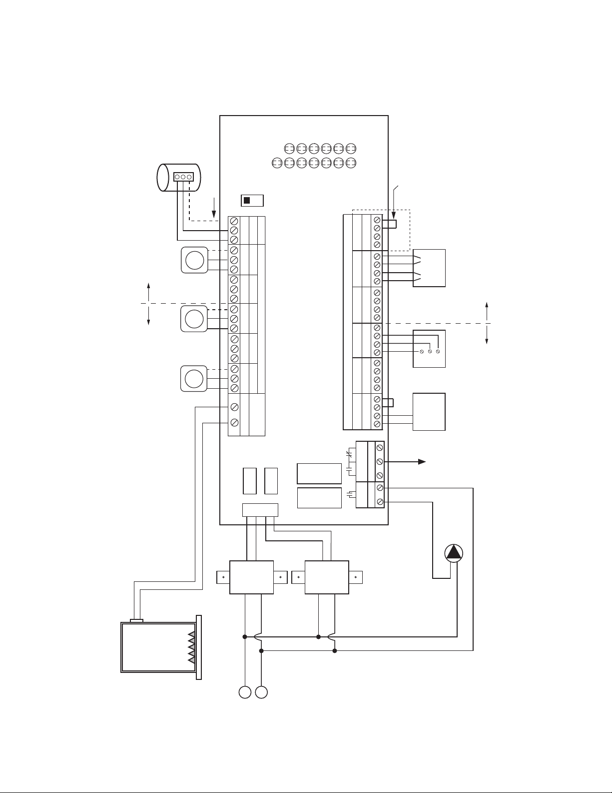
BOILER
H
N
SYSTEM
PUMP
SYSTEM PUMP AND BOILER TURN ON
WHEN ANY ZONE VALVE OPENS.
1 2 3 4
ZONE 1
1 2 3 4
ZONE 2
1 2 3 4
ZONE 3
1 2 3 4
ZONE 4
1 2 3 4
ZONE 5
1 2 3 4
ZONE 6
PRIORITY
ZONE
2 WIRE ZONE VALVE
(NO END SWITCH)
MUST USE JUMPER
TACO
3 WIRE
ZONE VALVE
123
JUMPER
3 & 4
MOTOR END
SWITCH
4 WIRE ZONE VALVE
(POWER OPEN,
SELF CLOSING)
JUMPER
3 & 4
ZVC 406 – 4
SIX ZONE
ZONE VALVE CONTROL
24 VAC
FACTORY
INSTALLED
TRANSFORMER
120 VAC
INPUT
WHITE
BLACK
POWER IN
24 VAC
24 VAC
FACTORY
INSTALLED
TRANSFORMER
120 VAC
INPUT
WHITE
BLACK
DRY
CONTACTS
N/O
COM
N/C
PUMP END
SWITCH
ZONE 6 PUMP
END SWITCH
THERMOSTATS (24VAC)
T STAT 1
VALVE 1
T STAT 2
VALVE 2
T STAT 3
VALVE 3
T STAT 4
VALVE 4
VALVE 5
T STAT 6
VALVE 6
POWER
LED
INDICATORS
T STAT 5
TO: BOILER AQUASTAT RELAY
ZONE 1 ZONE 2 ZONE 3 ZONE 4 ZONE 5 ZONE 6
ISOLATED
X X
END SWITCH THERMOSTATS (24 VAC) PRIORITY
24 VAC ZONE VALVES
PRIORITY
X X
ZONE 6
PRIORITY
OFF
ON
NOTE 2: When a circulator
is used on the priority zone
instead of a zone valve,
jumper 3 and 4 of the
priority zone.
FUSE
5 AMP
R W
INDIRECT
WATER HEATER
AQUASTAT OR
THERMOSTAT
See NOTE 1
R W
R W R WC C C
R W
C
C
FUSE
5 AMP
R W
C
NOTE 1: Terminals C are for
optional 24V thermostat
COMMON connections.
Powered from Transformer A Powered from Transformer B
A
B
Powered from Transformer A Powered from Transformer B
T T
T
ZVC403/404/405/406 with System Pump
28
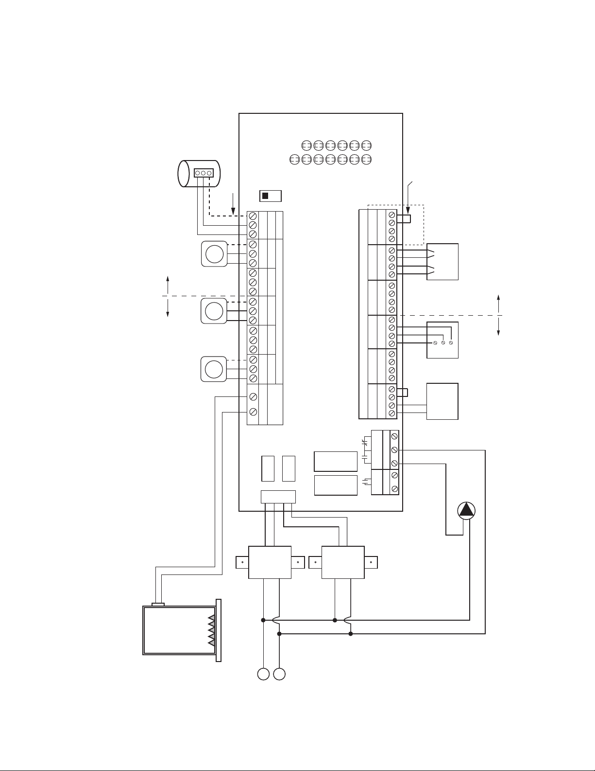
BOILER
H
N
DHW
PUMP
1 2 3 4
ZONE 1
1 2 3 4
ZONE 2
1 2 3 4
ZONE 3
1 2 3 4
ZONE 4
1 2 3 4
ZONE 5
1 2 3 4
ZONE 6
PRIORITY
ZONE
2 WIRE ZONE VALVE
(NO END SWITCH)
MUST USE JUMPER
TACO
3 WIRE
ZONE VALVE
123
JUMPER
3 & 4
MOTOR END
SWITCH
4 WIRE ZONE VALVE
(POWER OPEN,
SELF CLOSING)
JUMPER
3 & 4
ZVC 406 – 4
SIX ZONE
ZONE VALVE CONTROL
24 VAC
FACTORY
INSTALLED
TRANSFORMER
120 VAC
INPUT
WHITE
BLACK
POWER IN
24 VAC
24 VAC
FACTORY
INSTALLED
TRANSFORMER
120 VAC
INPUT
WHITE
BLACK
N/O
COM
N/C
PUMP END
SWITCH
ZONE 6 PUMP
END SWITCH
THERMOSTATS (24VAC)
T STAT 1
VALVE 1
T STAT 2
VALVE 2
T STAT 3
VALVE 3
T STAT 4
VALVE 4
VALVE 5
T STAT 6
VALVE 6
POWER
LED
INDICATORS
T STAT 5
TO: BOILER AQUASTAT RELAY
ZONE 1 ZONE 2 ZONE 3 ZONE 4 ZONE 5 ZONE 6
ISOLATED
X X
END SWITCH THERMOSTATS (24 VAC) PRIORITY
24 VAC ZONE VALVES
PRIORITY
X X
ZONE 6
PRIORITY
OFF
ON
NOTE 2: When a circulator
is used on the priority zone
instead of a zone valve,
jumper 3 and 4 of the
priority zone.
FUSE
5 AMP
R W
INDIRECT
WATER HEATER
AQUASTAT OR
THERMOSTAT
See NOTE 1
R W
R W R WC C C
R W
C
C
FUSE
5 AMP
R W
C
NOTE 1: Terminals C are for
optional 24V thermostat
COMMON connections.
Powered from Transformer A Powered from Transformer B
A
B
Powered from Transformer A Powered from Transformer B
BOILER TURNS ON WHEN ANY ZONE VALVE OPENS.
DHW PUMP TURNS ON ONLY WHEN PRIORITY ZONE CALLS.
T T
T
ZVC403/404/405/406 with Domestic Hot Water (DHW) Pump
29

BOILER
H
N
DHW
PUMP
1 2 3 4
ZONE 1
1 2 3 4
ZONE 2
1 2 3 4
ZONE 3
1 2 3 4
ZONE 4
1 2 3 4
ZONE 5
1 2 3 4
ZONE 6
PRIORITY
ZONE
2 WIRE ZONE VALVE
(NO END SWITCH)
MUST USE JUMPER
TACO
3 WIRE
ZONE VALVE
123
JUMPER
3 & 4
MOTOR END
SWITCH
4 WIRE ZONE VALVE
(POWER OPEN,
SELF CLOSING)
JUMPER
3 & 4
ZVC 406 – 4
SIX ZONE
ZONE VALVE CONTROL
24 VAC
FACTORY
INSTALLED
TRANSFORMER
120 VAC
INPUT
WHITE
BLACK
POWER IN
24 VAC
24 VAC
FACTORY
INSTALLED
TRANSFORMER
120 VAC
INPUT
WHITE
BLACK
N/O
COM
N/C
PUMP END
SWITCH
ZONE 6 PUMP
END SWITCH
THERMOSTATS (24VAC)
T STAT 1
VALVE 1
T STAT 2
VALVE 2
T STAT 3
VALVE 3
T STAT 4
VALVE 4
VALVE 5
T STAT 6
VALVE 6
POWER
LED
INDICATORS
T STAT 5
TO: BOILER AQUASTAT RELAY
ZONE 1 ZONE 2 ZONE 3 ZONE 4 ZONE 5 ZONE 6
ISOLATED
X X
END SWITCH THERMOSTATS (24 VAC) PRIORITY
24 VAC ZONE VALVES
PRIORITY
X X
ZONE 6
PRIORITY
OFF
ON
NOTE 2: When a circulator
is used on the priority zone
instead of a zone valve,
jumper 3 and 4 of the
priority zone.
FUSE
5 AMP
R W
INDIRECT
WATER HEATER
AQUASTAT OR
THERMOSTAT
See NOTE 1
R W
R W R WC C C
R W
C
C
FUSE
5 AMP
R W
C
NOTE 1: Terminals C are for
optional 24V thermostat
COMMON connections.
Powered from Transformer A Powered from Transformer B
A
B
Powered from Transformer A Powered from Transformer B
SYSTEM PUMP AND BOILER TURN ON WHEN ANY ZONE VALVE OPENS.
DHW PUMP TURNS ON ONLY WHEN PRIORITY ZONE CALLS.
SYSTEM
PUMP
T T
T
ZVC403/404/405/406 with System and DHW Pumps
30

BOILER
H
N
DHW
PUMP
1 2 3 4
ZONE 1
1 2 3 4
ZONE 2
1 2 3 4
ZONE 3
1 2 3 4
ZONE 4
1 2 3 4
ZONE 5
1 2 3 4
ZONE 6
PRIORITY
ZONE
2 WIRE ZONE VALVE
(NO END SWITCH)
MUST USE JUMPER
TACO
3 WIRE
ZONE VALVE
123
JUMPER
3 & 4
MOTOR END
SWITCH
4 WIRE ZONE VALVE
(POWER OPEN,
SELF CLOSING)
JUMPER
3 & 4
ZVC 406 – 4
SIX ZONE
ZONE VALVE CONTROL
24 VAC
FACTORY
INSTALLED
TRANSFORMER
120 VAC
INPUT
WHITE
BLACK
POWER IN
24 VAC
24 VAC
FACTORY
INSTALLED
TRANSFORMER
120 VAC
INPUT
WHITE
BLACK
N/O
COM
N/C
PUMP END
SWITCH
ZONE 6 PUMP
END SWITCH
THERMOSTATS (24VAC)
T STAT 1
VALVE 1
T STAT 2
VALVE 2
T STAT 3
VALVE 3
T STAT 4
VALVE 4
VALVE 5
T STAT 6
VALVE 6
POWER
LED
INDICATORS
T STAT 5
TO: BOILER AQUASTAT RELAY
ZONE 1 ZONE 2 ZONE 3 ZONE 4 ZONE 5 ZONE 6
ISOLATED
X X
END SWITCH THERMOSTATS (24 VAC) PRIORITY
24 VAC ZONE VALVES
PRIORITY
X X
ZONE 6
PRIORITY
OFF
ON
NOTE 2: When a circulator
is used on the priority zone
instead of a zone valve,
jumper 3 and 4 of the
priority zone.
FUSE
5 AMP
R W
INDIRECT
WATER HEATER
AQUASTAT OR
THERMOSTAT
See NOTE 1
R W
R W R WC C C
R W
C
C
FUSE
5 AMP
R W
C
NOTE 1: Terminals C are for
optional 24V thermostat
COMMON connections.
Powered from Transformer A Powered from Transformer B
A
B
Powered from Transformer A Powered from Transformer B
SYSTEM
PUMP
SECONDARY
PUMP
SYSTEM PUMP AND BOILER TURN ON WHEN ANY ZONE VALVE OPENS.
T T
T
ZVC403/404/405/406 with System, DHW and Secondary Pumps
31

2 ZVC403/404/405/406 Connected Together with Priority
1
234
ZONE 1
1
234
ZONE 2
1
234
ZONE 3
1
234
ZONE 4
PRIORITY
Z
ONE
2 WIRE ZONE VALVE
(NO END SWITCH)
M
UST USE JUMPER
T
ACO
3
WIRE
ZONE VALVE
1
2
3
J
UMPER
3
& 4
MOTOR END
S
WITCH
4
WIRE ZONE VALVE
(
POWER OPEN,
SELF CLOSING)
J
UMPER
3
& 4
ZVC 404 – 4
FOUR ZONE
ZONE VALVE CONTROL
24 VAC
FACTORY
INSTALLED
TRANSFORMER
120 VAC
I
NPUT
W
HITE
BLACK
POWER IN
24 VAC
T
O
C
IRCULATOR
DRY
CONTACTS
N/O
COM
N
/C
P
UMP END
SWITCH
FUSE
5 AMP
ZONE 4 PUMP
E
ND SWITCH
T STAT 1
VALVE 1
T STAT 2
VALVE 2
T STAT 3
VALVE 3
T
STAT 4
VALVE 4
POWER
L
ED
I
NDICATORS
ZONE 1 ZONE 2 ZONE 3 ZONE 4
ISOLATED
X
X
END SWITCH THERMOSTATS (24 VAC)
PRIORITY
24 VAC ZONE VALVES PRIORITY
X
X
Z
ONE 4
PRIORITY
OFF
ON
NOTE 2: When a circulator
is used on the priority zone
instead of a zone valve,
jumper 3 and 4 of the
priority zone.
THERMOSTATS (24VAC)
RW
RW RW
CCC
See NOTE 1
RW
C
NOTE 1: Terminals C are for
o
ptional 24V thermostat
COMMON connections.
1234
ZONE 1
1234
ZONE 2
1234
ZONE 3
1234
ZONE 4
PRIORITY
ZONE
2 WIRE ZONE VALVE
(NO END SWITCH)
MUST USE JUMPER
TACO
3 WIRE
ZONE VALVE
1
2
3
JUMPER
3 & 4
MOTOR END
SWITCH
4 WIRE ZONE VALVE
(POWER OPEN,
SELF CLOSING)
JUMPER
3 & 4
24 VAC
FACTORY
INSTALLED
TRANSFORMER
120 VAC
INPUT
WHITE
BLACK
POWER IN
24 VAC
TO
CIRCULATOR
DRY
CONTACTS
N/O
COM
N/C
PUMP END
SWITCH
FUSE
5 AMP
ZONE 4 PUMP
END SWITCH
T STAT 1
VALVE 1
T STAT 2
VALVE 2
T STAT 3
VALVE 3
T STAT 4
VALVE 4
POWER
LED
INDICATORS
TO: BOILER AQUASTAT RELAY
ZONE 1 ZONE 2 ZONE 3 ZONE 4
ISOLATED
XX
END SWITCH THERMOSTATS (24 VAC) PRIORITY
24 VAC ZONE VALVES PRIORITY
XX
ZONE 4
PRIORITY
OFF
ON
NOTE 2: When a circulator
is used on the priority zone
instead of a zone valve,
jumper 3 and 4 of the
priority zone.
THERMOSTATS (24VAC)
INDIRECT
WATER HEATER
AQUASTAT OR
THERMOSTAT
RW
RW RW
CCC
See NOTE 1
RW
C
BOILER
H
N
TO: BOILER AQUASTAT RELAY
PRIORITY
ON
P
RIORITY
ON
TTT
TTT
ZVC 404 – 4
FOUR ZONE
ZONE VALVE CONTROL
32

2 EXP Zone Valve Controls Connected Together with System Pump
24 VAC
FACTORY
INSTALLED
TRANSFORMER
120 VAC
INPUT
WHITE
BLACK
H
N
BOILER
24 VAC
FACTORY
INSTALLED
TRANSFORMER
120 VAC
INPUT
WHITE
BLACK
24 VAC
FACTORY
INSTALLED
TRANSFORMER
120 VAC
INPUT
WHITE
BLACK
24 VAC
FACTORY
INSTALLED
TRANSFORMER
120 VAC
INPUT
WHITE
BLACK
SWITCH SETTINGS
Master/Slave: Master
Priority Zone: On
Reset/Normal: Normal
SWITCH SETTINGS
Master/Slave: Slave
Priority Zone: Off
Reset/Normal: Normal
120 VAC
INPUT
MASTER
SLAVE
SYSTEM PUMP AND BOILER TURN ON
WHEN ANY ZONE VALVE OPENS.
SYSTEM
PUMP
DRY
CONTACTS
DRY
CONTACTS
T
O: BOILER AQUASTAT RELAY
TO: "TT" ON BOILER WITH
DHW "TT" INPUT
1234
ZONE 1
1234
ZONE 2
1234
ZONE 3
1234
ZONE 4
1234
ZONE 5
1234
ZONE 6
PRIORITY
ZONE
2 WIRE ZONE VALVE
(NO END SWITCH)
MUST USE JUMPER
TACO
3 WIRE
ZONE VALVE
1
2
3
JUMPER
3 & 4
MOTOR END
SWITCH
4 WIRE ZONE VALVE
(POWER OPEN,
SELF CLOSING)
JUMPER
3 & 4
ZVC 406-EXP-4
SIX ZONE EXPANDABLE
ZONE VALVE CONTROL
POWER IN
24 VAC
N/O COM
N/C
ZONE 6 PUMP
END SWITCH
SLAVE
PRIORITY ON
RESET
POST PURGE ON
PRIORITY PROTECTION ON
PUMP EXERCISE ON
30 SEC/2 WK
MASTER
OFF
NORMAL
OFF
OFF
OFF
4 MIN/24 HOUR
THERMOSTATS (24 VAC)
T STAT 1
VALVE 1
T STAT 2
VALVE 2
T STAT 3
VALVE 3
T STAT 4
VALVE 4
VALVE 5
T STAT 6
VALVE 6
POWER
LED
INDICATORS
T STAT 5
ZONE 1 ZONE 2 ZONE 3 ZONE 4 ZONE 5 ZONE 6 NET
EXPANSION
MAIN
PRIORITY
XX
XX
AB
CRW
CRW
CRW
CRW
CRW
CRW
C
12
END SWITCH THERMOSTATS (24 VAC)
PRIORITY
24 VAC ZONE VALVES
1234
ZONE 1
1234
ZONE 2
1234
ZONE 3
1234
ZONE 4
1234
ZONE 5
1234
ZONE 6
PRIORITY
ZONE
2 WIRE ZONE VALVE
(NO END SWITCH)
M
UST USE JUMPER
TACO
3 WIRE
ZONE VALVE
1
2
3
JUMPER
3
& 4
MOTOR END
SWITCH
4 WIRE ZONE VALVE
(POWER OPEN,
S
ELF CLOSING)
JUMPER
3 & 4
ZVC 406-EXP-4
SIX ZONE EXPANDABLE
ZONE VALVE CONTROL
POWER IN
24 VAC
N/O COM N/C
PUMP END
SWITCH
ZONE 6 PUMP
END SWITCH
S
LAVE
P
RIORITY ON
R
ESET
POST PURGE ON
PRIORITY PROTECTION ON
P
UMP EXERCISE ON
30 SEC/2 WK
MASTER
O
FF
N
ORMAL
OFF
OFF
O
FF
4 MIN/24 HOUR
THERMOSTATS (24 VAC)
I
NDIRECT
WATER HEATER
AQUASTAT OR
T
HERMOSTAT
T STAT 1
V
ALVE 1
T STAT 2
V
ALVE 2
T STAT 3
VALVE 3
T STAT 4
VALVE 4
V
ALVE 5
T
STAT 6
VALVE 6
POWER
LED
I
NDICATORS
T
STAT 5
ZONE 1 ZONE 2 ZONE 3 ZONE 4 ZONE 5 ZONE 6
N
ET
EXPANSION
MAIN
PRIORITY
XXXXAB
CRW
CRW
CRW
CRW
CRW
CRWC12
END SWITCH THERMOSTATS (24 VAC) PRIORITY
24 VAC ZONE VALVES
PRIORITY
PRIORITY
XX
PUMP END
SWITCH
XX
P
OWER
C
ONTROLS
A
CCESSORY
P
ORT
F
USE
5
AMP
FUSE
5 AMP
POWER
CONTROLS
ACCESSORY
PORT
FUSE
5 AMP
FUSE
5 AMP
NOTE 2: When a circulator
is used on the priority zone
instead of a zone valve,
jumper 3 and 4 of the
priority zone.
See NOTE 2
NOTE 1: Terminals C are for
optional 24V thermostat
COMMON connections.
Powered from Transformer A
A
B
A
B
Powered from Transformer A
Powered from Transformer B
Powered from Transformer A
Powered from Transformer B
Powered from Transformer B
See NOTE 1
TTT
TTT
33

2 EXP Zone Valve Controls Connected Together with DHW Pump
24 VAC
FACTORY
INSTALLED
TRANSFORMER
120 VAC
INPUT
W
HITE
BLACK
H
N
BOILER
24 VAC
FACTORY
INSTALLED
TRANSFORMER
120 VAC
INPUT
WHITE
BLACK
24 VAC
FACTORY
INSTALLED
TRANSFORMER
120 VAC
INPUT
WHITE
BLACK
24 VAC
FACTORY
INSTALLED
TRANSFORMER
120 VAC
INPUT
WHITE
BLACK
SWITCH SETTINGS
Master/Slave: Master
Priority Zone: On
Reset/Normal: Normal
SWITCH SETTINGS
Master/Slave: Slave
Priority Zone: Off
Reset/Normal: Normal
120 VAC
INPUT
MASTER
SLAVE
DHW
PUMP
DRY
CONTACTS
TO: BOILER AQUASTAT RELAY
T
O: "TT" ON BOILER WITH
DHW "TT" INPUT
1234
ZONE 1
1234
ZONE 2
1234
ZONE 3
1234
ZONE 4
1234
ZONE 5
1234
ZONE 6
PRIORITY
ZONE
2 WIRE ZONE VALVE
(NO END SWITCH)
MUST USE JUMPER
TACO
3 WIRE
ZONE VALVE
1
2
3
JUMPER
3 & 4
MOTOR END
SWITCH
4 WIRE ZONE VALVE
(POWER OPEN,
SELF CLOSING)
JUMPER
3 & 4
ZVC 406-EXP-4
SIX ZONE EXPANDABLE
ZONE VALVE CONTROL
POWER IN
24 VAC
N/O COM
N/C
ZONE 6 PUMP
END SWITCH
SLAVE
PRIORITY ON
RESET
POST PURGE ON
PRIORITY PROTECTION ON
PUMP EXERCISE ON
30 SEC/2 WK
MASTER
OFF
NORMAL
OFF
OFF
OFF
4 MIN/24 HOUR
THERMOSTATS (24 VAC)
T STAT 1
VALVE 1
T STAT 2
VALVE 2
T STAT 3
VALVE 3
T STAT 4
VALVE 4
VALVE 5
T STAT 6
VALVE 6
POWER
LED
INDICATORS
T STAT 5
ZONE 1 ZONE 2 ZONE 3 ZONE 4 ZONE 5 ZONE 6 NET
EXPANSION
MAIN
PRIORITY
XXXXAB
CRW
CRW
CRW
CRW
CRW
CRWC12
END SWITCH THERMOSTATS (24 VAC)
PRIORITY
24 VAC ZONE VALVES
1234
ZONE 1
1234
ZONE 2
1234
ZONE 3
1234
ZONE 4
1234
ZONE 5
1234
ZONE 6
PRIORITY
ZONE
2 WIRE ZONE VALVE
(NO END SWITCH)
M
UST USE JUMPER
TACO
3 WIRE
ZONE VALVE
1
2
3
JUMPER
3
& 4
M
OTOR END
SWITCH
4 WIRE ZONE VALVE
(
POWER OPEN,
S
ELF CLOSING)
JUMPER
3 & 4
ZVC 406-EXP-4
SIX ZONE EXPANDABLE
ZONE VALVE CONTROL
POWER IN
24 VAC
N
/O COMN/C
PUMP END
S
WITCH
ZONE 6 PUMP
E
ND SWITCH
SLAVE
PRIORITY ON
RESET
POST PURGE ON
PRIORITY PROTECTION ON
PUMP EXERCISE ON
3
0 SEC/2 WK
MASTER
OFF
NORMAL
OFF
OFF
OFF
4
MIN/24 HOUR
THERMOSTATS (24 VAC)
INDIRECT
WATER HEATER
AQUASTAT OR
T
HERMOSTAT
T STAT 1
VALVE 1
T STAT 2
VALVE 2
T
STAT 3
V
ALVE 3
T
STAT 4
V
ALVE 4
V
ALVE 5
T
STAT 6
V
ALVE 6
P
OWER
LED
INDICATORS
T STAT 5
ZONE 1 ZONE 2 ZONE 3 ZONE 4 ZONE 5 ZONE 6
NET
EXPANSION
MAIN
PRIORITY
XX
X
X
AB
C
RW
CRW
C
RW
CRW
C
RW
CRWC12
END SWITCH THERMOSTATS (24 VAC) PRIORITY
24 VAC ZONE VALVES
PRIORITY
PRIORITY
X
X
PUMP END
SWITCH
XX
P
OWER
C
ONTROLS
A
CCESSORY
P
ORT
FUSE
5 AMP
FUSE
5 AMP
POWER
CONTROLS
ACCESSORY
PORT
FUSE
5 AMP
FUSE
5 AMP
NOTE 2: When a circulator
is used on the priority zone
instead of a zone valve,
jumper 3 and 4 of the
priority zone.
See NOTE 2
NOTE 1: Terminals C are for
optional 24V thermostat
COMMON connections.
P
owered from Transformer A
A
B
A
B
Powered from Transformer A
Powered from Transformer B
Powered from Transformer A
Powered from Transformer B
P
owered from Transformer B
See NOTE 1
TTT
TTT
BOILER TURNS ON WHEN
ANY ZONE VALVE OPENS.
DHW PUMP TURNS ON ONLY
WHEN PRIORITY ZONE CALLS.
34

2 EXP Zone Valve Controls Connected Together with System and DHW Pumps
24 VAC
FACTORY
INSTALLED
TRANSFORMER
120 VAC
INPUT
WHITE
BLACK
H
N
BOILER
24 VAC
FACTORY
INSTALLED
TRANSFORMER
120 VAC
INPUT
WHITE
BLACK
24 VAC
FACTORY
INSTALLED
TRANSFORMER
120 VAC
INPUT
WHITE
BLACK
24 VAC
FACTORY
INSTALLED
TRANSFORMER
120 VAC
INPUT
WHITE
BLACK
SWITCH SETTINGS
Master/Slave: Master
Priority Zone: On
Reset/Normal: Normal
SWITCH SETTINGS
Master/Slave: Slave
Priority Zone: Off
Reset/Normal: Normal
120 VAC
INPUT
MASTER
SLAVE
DHW
PUMP
DRY
CONTACTS
T
O: BOILER AQUASTAT RELAY
TO: "TT" ON BOILER WITH
DHW "TT" INPUT
1234
ZONE 1
1234
ZONE 2
1234
ZONE 3
1234
ZONE 4
1234
ZONE 5
1234
ZONE 6
PRIORITY
ZONE
2 WIRE ZONE VALVE
(NO END SWITCH)
MUST USE JUMPER
TACO
3 WIRE
ZONE VALVE
1
2
3
JUMPER
3 & 4
MOTOR END
SWITCH
4 WIRE ZONE VALVE
(POWER OPEN,
SELF CLOSING)
JUMPER
3 & 4
ZVC 406-EXP-4
SIX ZONE EXPANDABLE
ZONE VALVE CONTROL
POWER IN
24 VAC
N/O COM
N/C
ZONE 6 PUMP
END SWITCH
SLAVE
PRIORITY ON
RESET
POST PURGE ON
PRIORITY PROTECTION ON
PUMP EXERCISE ON
30 SEC/2 WK
MASTER
OFF
NORMAL
OFF
OFF
OFF
4 MIN/24 HOUR
THERMOSTATS (24 VAC)
T STAT 1
VALVE 1
T STAT 2
VALVE 2
T STAT 3
VALVE 3
T STAT 4
VALVE 4
VALVE 5
T STAT 6
VALVE 6
POWER
LED
INDICATORS
T STAT 5
ZONE 1 ZONE 2 ZONE 3 ZONE 4 ZONE 5 ZONE 6 NET
EXPANSION
MAIN
PRIORITY
XXXXAB
CRW
CRW
CRW
CRW
CRW
CRWC12
END SWITCH THERMOSTATS (24 VAC)
PRIORITY
24 VAC ZONE VALVES
1
234
ZONE 1
1
234
ZONE 2
1
234
ZONE 3
1
234
ZONE 4
1
234
ZONE 5
1
234
ZONE 6
PRIORITY
ZONE
2
WIRE ZONE VALVE
(NO END SWITCH)
MUST USE JUMPER
TACO
3 WIRE
Z
ONE VALVE
1
2
3
JUMPER
3 & 4
MOTOR END
SWITCH
4
WIRE ZONE VALVE
(POWER OPEN,
SELF CLOSING)
J
UMPER
3 & 4
ZVC 406-EXP-4
S
IX ZONE EXPANDABLE
ZONE VALVE CONTROL
POWER IN
24 VAC
N
/O COMN/C
PUMP END
S
WITCH
ZONE 6 PUMP
E
ND SWITCH
SLAVE
P
RIORITY ON
RESET
POST PURGE ON
PRIORITY PROTECTION ON
P
UMP EXERCISE ON
30 SEC/2 WK
M
ASTER
O
FF
NORMAL
OFF
OFF
O
FF
4 MIN/24 HOUR
T
HERMOSTATS (24 VAC)
I
NDIRECT
W
ATER HEATER
A
QUASTAT OR
THERMOSTAT
T STAT 1
VALVE 1
T STAT 2
VALVE 2
T
STAT 3
V
ALVE 3
T
STAT 4
V
ALVE 4
VALVE 5
T
STAT 6
V
ALVE 6
P
OWER
LED
INDICATORS
T STAT 5
ZONE 1 ZONE 2 ZONE 3 ZONE 4 ZONE 5 ZONE 6
NET
EXPANSION
MAIN
PRIORITY
XXXXAB
CRW
CRW
CRW
CRW
CRW
CRWC12
E
ND SWITCH THERMOSTATS (24 VAC) PRIORITY
24 VAC ZONE VALVES
PRIORITY
PRIORITY
X
X
PUMP END
SWITCH
XX
POWER
CONTROLS
ACCESSORY
PORT
FUSE
5
AMP
FUSE
5 AMP
POWER
CONTROLS
ACCESSORY
PORT
FUSE
5 AMP
FUSE
5 AMP
NOTE 2: When a circulator
is used on the priority zone
instead of a zone valve,
jumper 3 and 4 of the
priority zone.
See NOTE 2
NOTE 1: Terminals C are for
optional 24V thermostat
COMMON connections.
Powered from Transformer A
A
B
A
B
Powered from Transformer A
Powered from Transformer B
Powered from Transformer A
Powered from Transformer B
Powered from Transformer B
See NOTE 1
TTT
TTT
SYSTEM PUMP AND BOILER TURN ON
WHEN ANY ZONE VALVE OPENS.
DHW PUMP TURNS ON ONLY
WHEN PRIORITY ZONE CALLS.
SYSTEM
PUMP
35

2 EXP Zone Valve Controls Connected Together with System, DHW and Secondary Pumps
24 VAC
FACTORY
INSTALLED
TRANSFORMER
120 VAC
INPUT
WHITE
BLACK
H
N
BOILER
24 VAC
FACTORY
INSTALLED
TRANSFORMER
120 VAC
INPUT
WHITE
B
LACK
24 VAC
FACTORY
INSTALLED
TRANSFORMER
120 VAC
INPUT
WHITE
BLACK
24 VAC
FACTORY
INSTALLED
TRANSFORMER
120 VAC
INPUT
WHITE
BLACK
SWITCH SETTINGS
Master/Slave: Master
Priority Zone: On
Reset/Normal: Normal
SWITCH SETTINGS
Master/Slave: Slave
Priority Zone: Off
Reset/Normal: Normal
120 VAC
INPUT
MASTER
SLAVE
DHW
PUMP
DRY
CONTACTS
T
O: BOILER AQUASTAT RELAY
TO: "TT" ON BOILER WITH
DHW "TT" INPUT
1234
ZONE 1
1234
ZONE 2
1234
ZONE 3
1234
ZONE 4
1234
ZONE 5
1234
ZONE 6
PRIORITY
ZONE
2 WIRE ZONE VALVE
(NO END SWITCH)
MUST USE JUMPER
TACO
3 WIRE
ZONE VALVE
1
2
3
JUMPER
3 & 4
MOTOR END
SWITCH
4 WIRE ZONE VALVE
(POWER OPEN,
SELF CLOSING)
JUMPER
3 & 4
ZVC 406-EXP-4
SIX ZONE EXPANDABLE
ZONE VALVE CONTROL
POWER IN
24 VAC
N/O COM
N/C
ZONE 6 PUMP
END SWITCH
SLAVE
PRIORITY ON
RESET
POST PURGE ON
PRIORITY PROTECTION ON
PUMP EXERCISE ON
30 SEC/2 WK
MASTER
OFF
NORMAL
OFF
OFF
OFF
4 MIN/24 HOUR
THERMOSTATS (24 VAC)
T STAT 1
VALVE 1
T STAT 2
VALVE 2
T STAT 3
VALVE 3
T STAT 4
VALVE 4
VALVE 5
T STAT 6
VALVE 6
POWER
LED
INDICATORS
T STAT 5
ZONE 1 ZONE 2 ZONE 3 ZONE 4 ZONE 5 ZONE 6 NET
EXPANSION
MAIN
PRIORITY
XX
XX
AB
CRW
CRW
CRW
CRW
CRW
CRW
C
12
END SWITCH THERMOSTATS (24 VAC)
PRIORITY
24 VAC ZONE VALVES
1234
ZONE 1
1234
ZONE 2
1234
ZONE 3
1234
ZONE 4
1234
ZONE 5
1234
ZONE 6
PRIORITY
ZONE
2
WIRE ZONE VALVE
(NO END SWITCH)
MUST USE JUMPER
T
ACO
3 WIRE
ZONE VALVE
1
2
3
JUMPER
3 & 4
MOTOR END
SWITCH
4
WIRE ZONE VALVE
(POWER OPEN,
SELF CLOSING)
JUMPER
3 & 4
ZVC 406-EXP-4
SIX ZONE EXPANDABLE
ZONE VALVE CONTROL
POWER IN
24 VAC
N
/O COMN/C
PUMP END
SWITCH
ZONE 6 PUMP
END SWITCH
SLAVE
PRIORITY ON
RESET
POST PURGE ON
PRIORITY PROTECTION ON
P
UMP EXERCISE ON
30 SEC/2 WK
M
ASTER
OFF
NORMAL
OFF
OFF
O
FF
4 MIN/24 HOUR
THERMOSTATS (24 VAC)
I
NDIRECT
W
ATER HEATER
A
QUASTAT OR
THERMOSTAT
T STAT 1
V
ALVE 1
T STAT 2
V
ALVE 2
T STAT 3
V
ALVE 3
T STAT 4
VALVE 4
V
ALVE 5
T
STAT 6
V
ALVE 6
P
OWER
L
ED
I
NDICATORS
T
STAT 5
ZONE 1 ZONE 2 ZONE 3 ZONE 4 ZONE 5 ZONE 6
NET
EXPANSION
MAIN
PRIORITY
X
X
XX
A
B
CRW
C
RW
CRW
C
RW
CRW
C
RW
C
1
2
END SWITCH THERMOSTATS (24 VAC) PRIORITY
24 VAC ZONE VALVES
PRIORITY
PRIORITY
X
X
PUMP END
SWITCH
XX
POWER
CONTROLS
ACCESSORY
PORT
FUSE
5 AMP
FUSE
5 AMP
POWER
CONTROLS
ACCESSORY
PORT
FUSE
5 AMP
FUSE
5 AMP
NOTE 2: When a circulator
is used on the priority zone
instead of a zone valve,
jumper 3 and 4 of the
priority zone.
See NOTE 2
NOTE 1: Terminals C are for
optional 24V thermostat
COMMON connections.
Powered from Transformer A
A
B
A
B
Powered from Transformer A
Powered from Transformer B
Powered from Transformer A
Powered from Transformer B
Powered from Transformer B
See NOTE 1
TTT
TTT
SYSTEM PUMP AND BOILER TURN ON
WHEN ANY ZONE VALVE OPENS.
DHW PUMP TURNS ON ONLY
WHEN PRIORITY ZONE CALLS.
SECONDARY PUMP COMES ON WHEN
ANY ZONE CALLS EXCEPT PRIORITY ZONE.
SYSTEM
PUMP
SECONDARY
PUMP
36

24 VAC
FACTORY
INSTALLED
TRANSFORMER
120 VAC
INPUT
WHITE
BLACK
H
N
BOILER
24 VAC
FACTORY
INSTALLED
TRANSFORMER
120 VAC
INPUT
WHITE
BLACK
SWITCH SETTINGS
Master/Slave: Master
Priority Zone: On or Off
Reset/Normal: Reset
120 VAC
INPUT
SYSTEM PUMP AND BOILER TURN ON
WHEN ANY ZONE VALVE OPENS.
SYSTEM
PUMP
DRY
CONTACTS
TO: BOILER AQUASTAT RELAY
TO: "TT" ON BOILER WITH
DHW "TT" INPUT
1 2 3 4
ZONE 1
1 2 3 4
ZONE 2
1 2 3 4
ZONE 3
1 2 3 4
ZONE 4
1 2 3 4
ZONE 5
1 2 3 4
ZONE 6
PRIORITY
ZONE
2 WIRE ZONE VALVE
(NO END SWITCH)
MUST USE JUMPER
TACO
3 WIRE
ZONE VALVE
123
JUMPER
3 & 4
MOTOR END
SWITCH
4 WIRE ZONE VALVE
(POWER OPEN,
SELF CLOSING)
JUMPER
3 & 4
ZVC 406-EXP-4
SIX ZONE EXPANDABLE
ZONE VALVE CONTROL
POWER IN
24 VAC
N/O COM N/C
PUMP END
SWITCH
ZONE 6 PUMP
END SWITCH
SLAVE
PRIORITY ON
RESET
POST PURGE ON
PRIORITY PROTECTION ON
PUMP EXERCISE ON
30 SEC/2 WK
MASTER
OFF
NORMAL
OFF
OFF
OFF
4 MIN/24 HOUR
THERMOSTATS (24 VAC)
INDIRECT
WATER HEATER
AQUASTAT OR
THERMOSTAT
T STAT 1
VALVE 1
T STAT 2
VALVE 2
T STAT 3
VALVE 3
T STAT 4
VALVE 4
VALVE 5
T STAT 6
VALVE 6
POWER
LED
INDICATORS
T STAT 5
ZONE 1 ZONE 2
ZONE 3
ZONE 4 ZONE 5 ZONE 6
NET
EXPANSION
MAIN
PRIORITY
X X
X X
A B
C R W
C R W
C R W
C R W
C R W
C R W
C
1 2
END SWITCH THERMOSTATS (24 VAC) PRIORITY
24 VAC ZONE VALVES PRIORITY
XX
POWER
CONTROLS
ACCESSORY
PORT
FUSE
5 AMP
FUSE
5 AMP
Powered from Transformer A
A
B
NOTE 2: When a circulator
is used on the priority zone
instead of a zone valve,
jumper 3 and 4 of the
priority zone.
NOTE 1: Terminals C are for
optional 24V thermostat
COMMON connections.
Powered from Transformer A
Powered from Transformer B
Powered from Transformer B
See NOTE 1
T T T
ZONE
CONTROL
BOIL
SEN
OUT
SEN
BOILER SENSOR
OUTDOOR
SENSOR
PC700
PC700 Boiler Reset Control Connected To EXP Zone Valve Control
37

24 VAC
FACTORY
INSTALLED
TRANSFORMER
120 VAC
INPUT
WHITE
BLACK
24 VAC
FACTORY
INSTALLED
TRANSFORMER
120 VAC
INPUT
WHITE
BLACK
SWITCH SETTINGS
Master/Slave: Master
Priority Zone: On or Off
Reset/Normal: Reset
SYSTEM
PUMP
1 2 3 4
ZONE 1
1 2 3 4
ZONE 2
1 2 3 4
ZONE 3
1 2 3 4
ZONE 4
1 2 3 4
ZONE 5
1 2 3 4
ZONE 6
PRIORITY
ZONE
2 WIRE ZONE VALVE
(NO END SWITCH)
MUST USE JUMPER
TACO
3 WIRE
ZONE VALVE
123
JUMPER
3 & 4
MOTOR END
SWITCH
4 WIRE ZONE VALVE
(POWER OPEN,
SELF CLOSING)
JUMPER
3 & 4
ZVC 406-EXP-4
SIX ZONE EXPANDABLE
ZONE VALVE CONTROL
POWER IN
24 VAC
N/O COM N/C
PUMP END
SWITCH
ZONE 6 PUMP
END SWITCH
SLAVE
PRIORITY ON
RESET
POST PURGE ON
PRIORITY PROTECTION ON
PUMP EXERCISE ON
30 SEC/2 WK
MASTER
OFF
NORMAL
OFF
OFF
OFF
4 MIN/24 HOUR
THERMOSTATS (24 VAC)
INDIRECT
WATER HEATER
AQUASTAT OR
THERMOSTAT
T STAT 1
VALVE 1
T STAT 2
VALVE 2
T STAT 3
VALVE 3
T STAT 4
VALVE 4
VALVE 5
T STAT 6
VALVE 6
POWER
LED
INDICATORS
T STAT 5
ZONE 1 ZONE 2
ZONE 3
ZONE 4 ZONE 5 ZONE 6
NET
EXPANSION
MAIN
PRIORITY
X X
X X
A B
C R W
C R W
C R W
C R W
C R W
C R W
C
1 2
END SWITCH THERMOSTATS (24 VAC) PRIORITY
24 VAC ZONE VALVES PRIORITY
XX
POWER
CONTROLS
ACCESSORY
PORT
FUSE
5 AMP
FUSE
5 AMP
Powered from Transformer A
A
B
NOTE 2: When a circulator
is used on the priority zone
instead of a zone valve,
jumper 3 and 4 of the
priority zone.
NOTE 1: Terminals C are for
optional 24V thermostat
COMMON connections.
Powered from Transformer A
Powered from Transformer B
Powered from Transformer B
See NOTE 1
T T T
BOILER
#2
ZONE
CONTROL
BOIL
SEN
OUT
SEN
BOILER SENSOR
OUTDOOR
SENSOR
PC702
STAGE
1
STAGE
2
BOILER
#1
DHW
DEMAND
WIRING NEEDED ONLY IF
PRIORITY ZONE IS DHW
SYSTEM PUMP AND BOILER TURN ON WHEN ANY ZONE VALVE OPENS.
DHW CIRCULATOR TURNS ON ONLY WHEN PRIORITY ZONE CALLS.
DHW
PUMP
H
N
120 VAC
INPUT
PC702 2–Stage Boiler Reset Control Connected To EXP Zone Valve Control
38

24 VAC
FACTORY
INSTALLED
TRANSFORMER
120 VAC
INPUT
WHITE
BLACK
H
N
BOILER
24 VAC
FACTORY
INSTALLED
TRANSFORMER
120 VAC
INPUT
WHITE
BLACK
SWITCH SETTINGS
Master/Slave: Master
Priority Zone: On or Off
Reset/Normal: Reset
120 VAC
INPUT
SYSTEM CIRCULATOR AND BOILER TURN ON
WHEN ANY ZONE VALVE OPENS.
SYSTEM CIRCULATOR
(OPTIONAL LOCATION)
DRY
CONTACTS
TO: BOILER AQUASTAT RELAY
TO: "TT" ON BOILER WITH
DHW "TT" INPUT
1 2 3 4
ZONE 1
1 2 3 4
ZONE 2
1 2 3 4
ZONE 3
1 2 3 4
ZONE 4
1 2 3 4
ZONE 5
1 2 3 4
ZONE 6
PRIORITY
ZONE
2 WIRE ZONE VALVE
(NO END SWITCH)
MUST USE JUMPER
TACO
3 WIRE
ZONE VALVE
123
JUMPER
3 & 4
MOTOR END
SWITCH
4 WIRE ZONE VALVE
(POWER OPEN,
SELF CLOSING)
JUMPER
3 & 4
ZVC 406-EXP-4
SIX ZONE EXPANDABLE
ZONE VALVE CONTROL
POWER IN
24 VAC
N/O COM N/C
PUMP END
SWITCH
ZONE 6 PUMP
END SWITCH
SLAVE
PRIORITY ON
RESET
POST PURGE ON
PRIORITY PROTECTION ON
PUMP EXERCISE ON
30 SEC/2 WK
MASTER
OFF
NORMAL
OFF
OFF
OFF
4 MIN/24 HOUR
THERMOSTATS (24 VAC)
INDIRECT
WATER HEATER
AQUASTAT OR
THERMOSTAT
T STAT 1
VALVE 1
T STAT 2
VALVE 2
T STAT 3
VALVE 3
T STAT 4
VALVE 4
VALVE 5
T STAT 6
VALVE 6
POWER
LED
INDICATORS
T STAT 5
ZONE 1 ZONE 2
ZONE 3
ZONE 4 ZONE 5 ZONE 6
NET
EXPANSION
MAIN
PRIORITY
X X
X X
A B
C R W
C R W
C R W
C R W
C R W
C R W
C
1 2
END SWITCH THERMOSTATS (24 VAC) PRIORITY
24 VAC ZONE VALVES PRIORITY
XX
POWER
CONTROLS
ACCESSORY
PORT
FUSE
5 AMP
FUSE
5 AMP
Powered from Transformer A
A
B
NOTE 2: When a circulator
is used on the priority zone
instead of a zone valve,
jumper 3 and 4 of the
priority zone.
NOTE 1: Terminals C are for
optional 24V thermostat
COMMON connections.
Powered from Transformer A
Powered from Transformer B
Powered from Transformer B
See NOTE 1
T T T
ZONE
CONTROL
BOIL
SEN
OUT
SEN
BOILER SENSOR
OUTDOOR
SENSOR
PC705-2
SUP
SEN
SUPPLY SENSOR
INJECTION
CIRCULATOR
SYSTEM
CIRCULATOR
AND/OR BOILER
BLACK
BLUE
RED
GREEN/GROUND
(SEE NOTE B
ON PAGE 22)
PC705 Variable Speed Pump Injection Control Connected To EXP Zone Valve Control
39

24 VAC
FACTORY
INSTALLED
TRANSFORMER
120 VAC
INPUT
WHITE
BLACK
H
N
BOILER
24 VAC
FACTORY
INSTALLED
TRANSFORMER
120 VAC
INPUT
WHITE
BLACK
24 VAC
FACTORY
INSTALLED
TRANSFORMER
120 VAC
INPUT
WHITE
BLACK
24 VAC
FACTORY
INSTALLED
TRANSFORMER
120 VAC
INPUT
WHITE
BLACK
SWITCH SETTINGS
M
aster/Slave: Master
P
riority Zone: On or Off
Reset/Normal: Reset
SWITCH SETTINGS
Master/Slave: Slave
Priority Zone: Off
Reset/Normal: Normal
120 VAC
INPUT
MASTER
SLAVE
DHW
PUMP
DRY
CONTACTS
T
O: BOILER AQUASTAT RELAY
TO: "TT" ON BOILER WITH
DHW "TT" INPUT
1234
ZONE 1
1234
ZONE 2
1234
ZONE 3
1234
ZONE 4
1234
ZONE 5
1234
ZONE 6
PRIORITY
ZONE
2 WIRE ZONE VALVE
(NO END SWITCH)
MUST USE JUMPER
TACO
3 WIRE
ZONE VALVE
1
2
3
JUMPER
3 & 4
MOTOR END
SWITCH
4 WIRE ZONE VALVE
(POWER OPEN,
SELF CLOSING)
JUMPER
3 & 4
ZVC 406-EXP-4
SIX ZONE EXPANDABLE
ZONE VALVE CONTROL
POWER IN
24 VAC
N/O COM
N/C
ZONE 6 PUMP
END SWITCH
SLAVE
PRIORITY ON
RESET
POST PURGE ON
PRIORITY PROTECTION ON
PUMP EXERCISE ON
30 SEC/2 WK
MASTER
OFF
NORMAL
OFF
OFF
OFF
4 MIN/24 HOUR
THERMOSTATS (24 VAC)
T STAT 1
VALVE 1
T STAT 2
VALVE 2
T STAT 3
VALVE 3
T STAT 4
VALVE 4
VALVE 5
T STAT 6
VALVE 6
POWER
LED
INDICATORS
T STAT 5
ZONE 1 ZONE 2 ZONE 3 ZONE 4 ZONE 5 ZONE 6 NET
EXPANSION
MAIN
PRIORITY
XX
XX
AB
CRW
CRW
CRW
CRW
CRW
CRWC12
END SWITCH THERMOSTATS (24 VAC)
PRIORITY
24 VAC ZONE VALVES
1234
Z
ONE 1
1234
Z
ONE 2
1234
Z
ONE 3
1234
Z
ONE 4
1234
Z
ONE 5
1234
Z
ONE 6
PRIORITY
ZONE
2 WIRE ZONE VALVE
(NO END SWITCH)
MUST USE JUMPER
TACO
3
WIRE
ZONE VALVE
1
2
3
J
UMPER
3 & 4
MOTOR END
SWITCH
4 WIRE ZONE VALVE
(
POWER OPEN,
SELF CLOSING)
JUMPER
3 & 4
ZVC 406-EXP-4
SIX ZONE EXPANDABLE
ZONE VALVE CONTROL
POWER IN
24 VAC
N/O COM N/C
P
UMP END
SWITCH
Z
ONE 6 PUMP
END SWITCH
S
LAVE
PRIORITY ON
RESET
P
OST PURGE ON
PRIORITY PROTECTION ON
PUMP EXERCISE ON
30 SEC/2 WK
MASTER
OFF
NORMAL
O
FF
OFF
OFF
4 MIN/24 HOUR
THERMOSTATS (24 VAC)
INDIRECT
WATER HEATER
AQUASTAT OR
THERMOSTAT
T
STAT 1
V
ALVE 1
T STAT 2
V
ALVE 2
T STAT 3
VALVE 3
T STAT 4
VALVE 4
V
ALVE 5
T STAT 6
VALVE 6
P
OWER
LED
INDICATORS
T STAT 5
ZONE 1 ZONE 2 ZONE 3 ZONE 4 ZONE 5 ZONE 6
NET
EXPANSION
MAIN
PRIORITY
XXXXAB
CRW
CRW
CRW
CRW
CRW
CRWC12
END SWITCH THERMOSTATS (24 VAC) PRIORITY
24 VAC ZONE VALVES
PRIORITY
PRIORITY
XX
PUMP END
SWITCH
XX
P
OWER
CONTROLS
A
CCESSORY
PORT
FUSE
5 AMP
FUSE
5 AMP
POWER
CONTROLS
ACCESSORY
PORT
FUSE
5 AMP
FUSE
5 AMP
NOTE 2: When a circulator
is used on the priority zone
instead of a zone valve,
jumper 3 and 4 of the
priority zone.
S
ee NOTE 2
NOTE 1: Terminals C are for
optional 24V thermostat
COMMON connections.
Powered from Transformer A
A
B
A
B
Powered from Transformer A
Powered from Transformer B
Powered from Transformer A
Powered from Transformer B
Powered from Transformer B
See NOTE 1
TTT
TTT
SYSTEM PUMP AND BOILER TURN ON
WHEN ANY ZONE VALVE OPENS.
DHW PUMP TURNS ON ONLY
WHEN PRIORITY ZONE CALLS.
SYSTEM
PUMP
ZONE
CONTROL
BOIL
SEN
OUT
SEN
B
OILER SENSOR
OUTDOOR
SENSOR
PC700
PC700 Boiler Reset Control Connected To 2 EXP Zone Valve Controls
40

24 VAC
FACTORY
INSTALLED
TRANSFORMER
120 VAC
INPUT
WHITE
BLACK
H
N
24 VAC
FACTORY
INSTALLED
TRANSFORMER
120 VAC
INPUT
WHITE
BLACK
24 VAC
FACTORY
INSTALLED
TRANSFORMER
120 VAC
INPUT
WHITE
BLACK
24 VAC
FACTORY
INSTALLED
TRANSFORMER
120 VAC
INPUT
WHITE
BLACK
SWITCH SETTINGS
M
aster/Slave: Master
P
riority Zone: On or Off
Reset/Normal: Reset
SWITCH SETTINGS
Master/Slave: Slave
Priority Zone: Off
Reset/Normal: Normal
120 VAC
INPUT
MASTER
SLAVE
DHW
PUMP
DRY
CONTACTS
1234
ZONE 1
1234
ZONE 2
1234
ZONE 3
1234
ZONE 4
1234
ZONE 5
1234
ZONE 6
PRIORITY
ZONE
2 WIRE ZONE VALVE
(NO END SWITCH)
MUST USE JUMPER
TACO
3 WIRE
ZONE VALVE
1
2
3
JUMPER
3 & 4
MOTOR END
SWITCH
4 WIRE ZONE VALVE
(POWER OPEN,
SELF CLOSING)
JUMPER
3 & 4
ZVC 406-EXP-4
SIX ZONE EXPANDABLE
ZONE VALVE CONTROL
POWER IN
24 VAC
N/O COM
N/C
ZONE 6 PUMP
END SWITCH
SLAVE
PRIORITY ON
RESET
POST PURGE ON
PRIORITY PROTECTION ON
PUMP EXERCISE ON
30 SEC/2 WK
MASTER
OFF
NORMAL
OFF
OFF
OFF
4 MIN/24 HOUR
THERMOSTATS (24 VAC)
T STAT 1
VALVE 1
T STAT 2
VALVE 2
T STAT 3
VALVE 3
T STAT 4
VALVE 4
VALVE 5
T STAT 6
VALVE 6
POWER
LED
INDICATORS
T STAT 5
ZONE 1 ZONE 2 ZONE 3 ZONE 4 ZONE 5 ZONE 6 NET
EXPANSION
MAIN
PRIORITY
XXXXAB
CRW
CRW
CRW
CRW
CRW
CRWC12
END SWITCH THERMOSTATS (24 VAC)
PRIORITY
24 VAC ZONE VALVES
1
234
ZONE 1
1
234
ZONE 2
1
234
ZONE 3
1
234
ZONE 4
1
234
ZONE 5
1
234
ZONE 6
PRIORITY
ZONE
2 WIRE ZONE VALVE
(NO END SWITCH)
M
UST USE JUMPER
TACO
3 WIRE
ZONE VALVE
1
2
3
JUMPER
3
& 4
MOTOR END
SWITCH
4 WIRE ZONE VALVE
(POWER OPEN,
S
ELF CLOSING)
JUMPER
3 & 4
ZVC 406-EXP-4
SIX ZONE EXPANDABLE
ZONE VALVE CONTROL
POWER IN
24 VAC
N/O COM N/C
PUMP END
SWITCH
ZONE 6 PUMP
END SWITCH
SLAVE
P
RIORITY ON
RESET
POST PURGE ON
PRIORITY PROTECTION ON
P
UMP EXERCISE ON
30 SEC/2 WK
M
ASTER
O
FF
NORMAL
OFF
OFF
O
FF
4 MIN/24 HOUR
THERMOSTATS (24 VAC)
I
NDIRECT
W
ATER HEATER
A
QUASTAT OR
T
HERMOSTAT
T STAT 1
VALVE 1
T STAT 2
VALVE 2
T
STAT 3
V
ALVE 3
T
STAT 4
V
ALVE 4
VALVE 5
T
STAT 6
V
ALVE 6
P
OWER
LED
INDICATORS
T STAT 5
ZONE 1 ZONE 2 ZONE 3 ZONE 4 ZONE 5 ZONE 6
NET
EXPANSION
MAIN
PRIORITY
XX
X
X
AB
C
RW
CRW
C
RW
CRW
C
RW
CRWC12
E
ND SWITCH THERMOSTATS (24 VAC) PRIORITY
24 VAC ZONE VALVES
PRIORITY
PRIORITY
XX
PUMP END
SWITCH
XX
P
OWER
C
ONTROLS
ACCESSORY
P
ORT
FUSE
5 AMP
FUSE
5 AMP
POWER
CONTROLS
ACCESSORY
PORT
FUSE
5 AMP
FUSE
5 AMP
NOTE 2: When a circulator
is used on the priority zone
instead of a zone valve,
jumper 3 and 4 of the
priority zone.
See NOTE 2
NOTE 1: Terminals C are for
optional 24V thermostat
COMMON connections.
Powered from Transformer A
A
B
A
B
Powered from Transformer A
Powered from Transformer B
Powered from Transformer A
Powered from Transformer B
Powered from Transformer B
See NOTE 1
TTT
TTT
SYSTEM PUMP AND BOILER TURN ON
WHEN ANY ZONE VALVE OPENS.
DHW PUMP TURNS ON ONLY
WHEN PRIORITY ZONE CALLS.
SYSTEM
PUMP
ZONE
CONTROL
BOIL
SEN
OUT
SEN
B
OILER SENSOR
O
UTDOOR
S
ENSOR
PC702
STAGE1STAGE
2
BOILER
#2
BOILER
#1
DHW
DEMAND
W
IRING NEEDED ONLY IF
PRIORITY ZONE IS DHW
PC702 2–Stage Boiler Reset Control Connected To 2 EXP Zone Valve Controls
41

PC705 Variable Speed Pump Injection Control Connected To 2 EXP Zone Valve Controls
24 VAC
FACTORY
INSTALLED
TRANSFORMER
120 VAC
INPUT
WHITE
BLACK
H
N
B
OILER
24 VAC
FACTORY
INSTALLED
TRANSFORMER
120 VAC
INPUT
WHITE
BLACK
24 VAC
FACTORY
INSTALLED
TRANSFORMER
120 VAC
INPUT
WHITE
BLACK
24 VAC
FACTORY
INSTALLED
TRANSFORMER
120 VAC
INPUT
WHITE
BLACK
S
WITCH SETTINGS
Master/Slave: Master
Priority Zone: On or Off
R
eset/Normal: Reset
SWITCH SETTINGS
Master/Slave: Slave
Priority Zone: Off
Reset/Normal: Normal
120 VAC
INPUT
MASTER
SLAVE
DRY
CONTACTS
TO: BOILER
AQUASTAT RELAY
TO: "TT" ON BOILER WITH
DHW "TT" INPUT
1234
ZONE 1
1234
ZONE 2
1234
ZONE 3
1234
ZONE 4
1234
ZONE 5
1234
ZONE 6
PRIORITY
ZONE
2 WIRE ZONE VALVE
(NO END SWITCH)
MUST USE JUMPER
TACO
3 WIRE
ZONE VALVE
1
2
3
JUMPER
3 & 4
MOTOR END
SWITCH
4 WIRE ZONE VALVE
(POWER OPEN,
SELF CLOSING)
JUMPER
3 & 4
ZVC 406-EXP-4
SIX ZONE EXPANDABLE
ZONE VALVE CONTROL
POWER IN
24 VAC
N/O COM N/C
ZONE 6 PUMP
END SWITCH
SLAVE
PRIORITY ON
RESET
POST PURGE ON
PRIORITY PROTECTION ON
PUMP EXERCISE ON
30 SEC/2 WK
MASTER
OFF
NORMAL
OFF
OFF
OFF
4 MIN/24 HOUR
THERMOSTATS (24 VAC)
T STAT 1
VALVE 1
T STAT 2
VALVE 2
T STAT 3
VALVE 3
T STAT 4
VALVE 4
VALVE 5
T STAT 6
VALVE 6
POWER
LED
INDICATORS
T STAT 5
ZONE 1 ZONE 2 ZONE 3 ZONE 4 ZONE 5 ZONE 6 NET
EXPANSION
MAIN
PRIORITY
XXXXAB
CRW
CRW
CRW
CRW
CRW
CRWC12
END SWITCH THERMOSTATS (24 VAC)
PRIORITY
24 VAC ZONE VALVES
1234
ZONE 1
1234
ZONE 2
1234
ZONE 3
1234
ZONE 4
1234
ZONE 5
1234
ZONE 6
PRIORITY
ZONE
2 WIRE ZONE VALVE
(NO END SWITCH)
M
UST USE JUMPER
TACO
3
WIRE
ZONE VALVE
1
2
3
JUMPER
3
& 4
MOTOR END
SWITCH
4 WIRE ZONE VALVE
(POWER OPEN,
SELF CLOSING)
JUMPER
3 & 4
ZVC 406-EXP-4
SIX ZONE EXPANDABLE
Z
ONE VALVE CONTROL
POWER IN
24 VAC
N/O COM N/C
PUMP END
SWITCH
ZONE 6 PUMP
END SWITCH
S
LAVE
PRIORITY ON
RESET
POST PURGE ON
P
RIORITY PROTECTION ON
PUMP EXERCISE ON
30 SEC/2 WK
MASTER
OFF
NORMAL
OFF
O
FF
OFF
4 MIN/24 HOUR
THERMOSTATS (24 VAC)
I
NDIRECT
W
ATER HEATER
A
QUASTAT OR
T
HERMOSTAT
T
STAT 1
V
ALVE 1
T
STAT 2
V
ALVE 2
T STAT 3
VALVE 3
T STAT 4
VALVE 4
V
ALVE 5
T STAT 6
VALVE 6
P
OWER
LED
INDICATORS
T STAT 5
ZONE 1 ZONE 2 ZONE 3 ZONE 4 ZONE 5 ZONE 6
NET
EXPANSION
MAIN
PRIORITY
X
X
XX
A
B
CRW
C
RW
CRW
C
RW
CRW
C
RW
C
1
2
END SWITCH THERMOSTATS (24 VAC) PRIORITY
24 VAC ZONE VALVES
PRIORITY
PRIORITY
XX
PUMP END
SWITCH
XX
POWER
C
ONTROLS
A
CCESSORY
P
ORT
FUSE
5
AMP
FUSE
5 AMP
POWER
CONTROLS
ACCESSORY
PORT
FUSE
5 AMP
FUSE
5 AMP
NOTE 2: When a circulator
is used on the priority zone
instead of a zone valve,
jumper 3 and 4 of the
priority zone.
See NOTE 2
NOTE 1: Terminals C are for
optional 24V thermostat
COMMON connections.
Powered from Transformer A
A
B
A
B
Powered from Transformer A
Powered from Transformer B
Powered from Transformer A
Powered from Transformer B
P
owered from Transformer B
S
ee NOTE 1
TTT
TTT
SYSTEM
CIRCULATOR
(OPTIONAL LOCATION)
ZONE
CONTROL
BOIL
SEN
OUT
SEN
BOILER SENSOR
OUTDOOR
SENSOR
PC705-2
SUP
SEN
SUPPLY SENSOR
INJECTION
CIRCULATOR
SYSTEM
CIRCULATOR
BLACK
B
LUE
RED
GREEN/GROUND
(SEE NOTE B
ON PAGE 22)
42

PC700 and PC705 Connected To 2 EXP Zone Valve Controls
24 VAC
FACTORY
INSTALLED
TRANSFORMER
120 VAC
INPUT
WHITE
BLACK
H
N
B
OILER
24 VAC
FACTORY
INSTALLED
TRANSFORMER
120 VAC
INPUT
WHITE
BLACK
24 VAC
FACTORY
INSTALLED
TRANSFORMER
120 VAC
INPUT
WHITE
BLACK
24 VAC
FACTORY
INSTALLED
TRANSFORMER
120 VAC
INPUT
WHITE
BLACK
S
WITCH SETTINGS
Master/Slave: Master
P
riority Zone: On or Off
Reset/Normal: Reset
SWITCH SETTINGS
Master/Slave: Slave
Priority Zone: Off
Reset/Normal: Reset
120 VAC
INPUT
MASTER
SLAVE
DHW
PUMP
DRY
CONTACTS
TO: BOILER AQUASTAT RELAY
TO: "TT" ON BOILER WITH
DHW "TT" INPUT
1234
ZONE 1
1234
ZONE 2
1234
ZONE 3
1234
ZONE 4
1234
ZONE 5
1234
ZONE 6
PRIORITY
ZONE
2 WIRE ZONE VALVE
(NO END SWITCH)
MUST USE JUMPER
TACO
3 WIRE
ZONE VALVE
1
2
3
JUMPER
3 & 4
MOTOR END
SWITCH
4 WIRE ZONE VALVE
(POWER OPEN,
SELF CLOSING)
JUMPER
3 & 4
ZVC 406-EXP-4
SIX ZONE EXPANDABLE
ZONE VALVE CONTROL
POWER IN
24 VAC
N/O COM
N/C
ZONE 6 PUMP
END SWITCH
SLAVE
PRIORITY ON
RESET
POST PURGE ON
PRIORITY PROTECTION ON
PUMP EXERCISE ON
30 SEC/2 WK
MASTER
OFF
NORMAL
OFF
OFF
OFF
4 MIN/24 HOUR
THERMOSTATS (24 VAC)
T STAT 1
VALVE 1
T STAT 2
VALVE 2
T STAT 3
VALVE 3
T STAT 4
VALVE 4
VALVE 5
T STAT 6
VALVE 6
POWER
LED
INDICATORS
T STAT 5
ZONE 1 ZONE 2 ZONE 3 ZONE 4 ZONE 5 ZONE 6 NET
EXPANSION
MAIN
PRIORITY
XX
XX
AB
CRW
CRW
CRW
CRW
CRW
CRW
C
12
END SWITCH THERMOSTATS (24 VAC)
PRIORITY
24 VAC ZONE VALVES
1234
ZONE 1
1234
ZONE 2
1234
ZONE 3
1234
ZONE 4
1234
ZONE 5
1234
ZONE 6
PRIORITY
ZONE
2 WIRE ZONE V
(NO END SWITCH)
MUST USE JUMPER
T
ACO
3 WIRE
ZONE VALVE
1
2
3
J
UMPER
3 & 4
MOTOR END
S
WITCH
4
WIRE ZONE VALVE
(POWER OPEN,
SELF CLOSING)
JUMPER
3
& 4
ZVC 406-EXP-4
SIX ZONE EXPANDABLE
Z
ONE VALVE CONTROL
POWER IN
24 VAC
N/O COM N/C
P
UMP END
SWITCH
Z
ONE 6 PUMP
END SWITCH
SLAVE
PRIORITY ON
R
ESET
POST PURGE ON
PRIORITY PROTECTION ON
P
UMP EXERCISE ON
30 SEC/2 WK
MASTER
OFF
N
ORMAL
OFF
OFF
O
FF
4 MIN/24 HOUR
THERMOSTATS (24 VAC)
INDIRECT
W
ATER HEATER
AQUASTAT OR
THERMOSTAT
T
STAT 1
VALVE 1
T
STAT 2
VALVE 2
T
STAT 3
VALVE 3
T STAT 4
V
ALVE 4
VALVE 5
T STAT 6
VALVE 6
P
OWER
LED
I
NDICATORS
T
STAT 5
ZONE 1 ZONE 2 ZONE 3 ZONE 4 ZONE 5 ZONE 6
NET
EXPANSION
MAIN
PRIORITY
XX
X
X
AB
C
RW
CRW
C
RW
CRW
C
RW
CRWC12
END SWITCH THERMOSTATS (24 VAC) PRIORITY
24 VAC ZONE VALVES
PRIORITY
PRIORITY
XX
PUMP END
SWITCH
XX
POWER
CONTROLS
ACCESSORY
PORT
F
USE
5 AMP
FUSE
5 AMP
POWER
CONTROLS
ACCESSORY
PORT
FUSE
5 AMP
FUSE
5 AMP
NOTE 2: When a circulator
is used on the priority zone
instead of a zone valve,
jumper 3 and 4 of the
priority zone.
See NOTE 2
NOTE 1: Terminals C are for
optional 24V thermostat
COMMON connections.
P
owered from Transformer A
A
B
A
B
Powered from Transformer A
Powered from Transformer B
Powered from Transformer A Powered from Transformer B
P
owered from Transformer B
See NOTE 1
TTT
TTT
S
YSTEM PUMP AND BOILER TURN ON
WHEN ANY ZONE VALVE OPENS.
SYSTEM
PUMP
ZONE
CONTROL
BOIL
SEN
OUT
SEN
BOILER SENSOR
OUTDOOR
SENSOR
PC700
ZONE
CONTROL
BOIL
SEN
OUT
SEN
BOILER SENSOR
OUTDOOR
SENSOR
PC705-2
SUP
SEN
SUPPLY SENSOR
INJECTION
CIRCULATOR
SYSTEM
C
IRCULATOR
BLACK
BLUE
RED
GREEN/GROUND
(SEE NOTE B
ON PAGE 22)
DHW PUMP TURNS ON ONLY
W
HEN PRIORITY ZONE CALLS.
43

24 VAC
FACTORY
INSTALLED
TRANSFORMER
120 VAC
INPUT
WHITE
BLACK
H
N
24 VAC
FACTORY
INSTALLED
TRANSFORMER
120 VAC
INPUT
W
HITE
BLACK
24 VAC
FACTORY
INSTALLED
TRANSFORMER
120 VAC
INPUT
WHITE
BLACK
24 VAC
FACTORY
INSTALLED
TRANSFORMER
120 VAC
INPUT
WHITE
BLACK
S
WITCH SETTINGS
Master/Slave: Master
Priority Zone: On or Off
R
eset/Normal: Reset
SWITCH SETTINGS
Master/Slave: Slave
Priority Zone: Off
Reset/Normal: Reset
120 VAC
INPUT
MASTER
SLAVE
DHW
PUMP
DRY
CONTACTS
1234
ZONE 1
1234
ZONE 2
1234
ZONE 3
1234
ZONE 4
1234
ZONE 5
1234
ZONE 6
PRIORITY
ZONE
2 WIRE ZONE VALVE
(NO END SWITCH)
MUST USE JUMPER
TACO
3 WIRE
ZONE VALVE
1
2
3
JUMPER
3 & 4
MOTOR END
SWITCH
4 WIRE ZONE VALVE
(POWER OPEN,
SELF CLOSING)
JUMPER
3 & 4
ZVC 406-EXP-4
SIX ZONE EXPANDABLE
ZONE VALVE CONTROL
POWER IN
24 VAC
N/O COM
N/C
ZONE 6 PUMP
END SWITCH
SLAVE
PRIORITY ON
RESET
POST PURGE ON
PRIORITY PROTECTION ON
PUMP EXERCISE ON
30 SEC/2 WK
MASTER
OFF
NORMAL
OFF
OFF
OFF
4 MIN/24 HOUR
THERMOSTATS (24 VAC)
T STAT 1
VALVE 1
T STAT 2
VALVE 2
T STAT 3
VALVE 3
T STAT 4
VALVE 4
VALVE 5
T STAT 6
VALVE 6
POWER
LED
INDICATORS
T STAT 5
ZONE 1 ZONE 2 ZONE 3 ZONE 4 ZONE 5 ZONE 6 NET
EXPANSION
MAIN
PRIORITY
XX
XX
AB
CRW
CRW
CRW
CRW
CRW
CRWC12
END SWITCH THERMOSTATS (24 VAC)
PRIORITY
24 VAC ZONE VALVES
1234
ZONE 1
1234
ZONE 2
1234
ZONE 3
1234
ZONE 4
1234
ZONE 5
1234
ZONE 6
P
RIORITY
ZONE
2 WIRE ZONE VALVE
(
NO END SWITCH)
MUST USE JUMPER
TACO
3
WIRE
ZONE VALVE
1
2
3
J
UMPER
3 & 4
MOTOR END
SWITCH
4 WIRE ZONE VALVE
(POWER OPEN,
SELF CLOSING)
JUMPER
3 & 4
ZVC 406-EXP-4
SIX ZONE EXPANDABLE
Z
ONE VALVE CONTROL
POWER IN
24 VAC
N/O COM N/C
PUMP END
SWITCH
ZONE 6 PUMP
END SWITCH
SLAVE
PRIORITY ON
RESET
POST PURGE ON
PRIORITY PROTECTION ON
PUMP EXERCISE ON
3
0 SEC/2 WK
MASTER
OFF
NORMAL
OFF
OFF
OFF
4
MIN/24 HOUR
THERMOSTATS (24 VAC)
I
NDIRECT
WATER HEATER
AQUASTAT OR
THERMOSTAT
T STAT 1
V
ALVE 1
T STAT 2
VALVE 2
T
STAT 3
V
ALVE 3
T
STAT 4
V
ALVE 4
V
ALVE 5
T
STAT 6
V
ALVE 6
P
OWER
LED
INDICATORS
T STAT 5
ZONE 1 ZONE 2 ZONE 3 ZONE 4 ZONE 5 ZONE 6
NET
EXPANSION
MAIN
PRIORITY
XXXXAB
CRW
CRW
CRW
CRW
CRW
CRWC12
END SWITCH THERMOSTATS (24 VAC) PRIORITY
24 VAC ZONE VALVES
PRIORITY
PRIORITY
XX
PUMP END
SWITCH
XX
POWER
CONTROLS
A
CCESSORY
PORT
FUSE
5 AMP
FUSE
5 AMP
POWER
CONTROLS
ACCESSORY
PORT
FUSE
5 AMP
FUSE
5 AMP
NOTE 2: When a circulator
is used on the priority zone
instead of a zone valve,
jumper 3 and 4 of the
priority zone.
See NOTE 2
NOTE 1: Terminals C are for
optional 24V thermostat
COMMON connections.
P
owered from Transformer A
A
B
A
B
Powered from Transformer A
Powered from Transformer B
Powered from Transformer A
Powered from Transformer B
P
owered from Transformer B
See NOTE 1
TTT
TTT
S
YSTEM PUMP AND BOILER TURN ON
WHEN ANY ZONE VALVE OPENS.
SYSTEM
PUMP
ZONE
CONTROL
BOIL
SEN
OUT
SEN
BOILER SENSOR
OUTDOOR
SENSOR
PC702
STAGE1STAGE
2
BOILER
#2
BOILER
#1
D
HW
D
EMAND
W
IRING NEEDED ONLY IF
PRIORITY ZONE IS DHW
D
HW PUMP TURNS ON ONLY
WHEN PRIORITY ZONE CALLS.
ZONE
CONTROL
BOIL
SEN
OUT
SEN
BOILER SENSOR
OUTDOOR
SENSOR
PC705-2
SUP
SEN
SUPPLY SENSOR
INJECTION
CIRCULATOR
S
YSTEM
C
IRCULATOR
BLACK
B
LUE
R
ED
GREEN/GROUND
(SEE NOTE B
ON PAGE 22)
PC702 and PC705 Connected To 2 EXP Zone Valve Controls
44

HAFC201-4
HYDRO AIR FAN CONTROL
THERMOSTAT
P
OWER
HEAT CALL
L
ED
I
NDICATORS
THERMOSTAT
T
C
RWYG
AQUASTATS
T
T
HAFC201-4
COOL FAN
HEAT FAN
BOILER
C
AIR HANDLER
XX RYG
L GH
WATER
COIL
FREEZE
PROT.
T
T
XX
PUMP
1 MIN FAN DELAY
3 MIN FAN DELAY
2MIN/24HR or 30SEC/2WK
PUMP EXERCISE
OFF ON
HAFC 201 WITH 1 SPEED AIR HANDLER
(HAFC 201 is capable of 1 and 2 speed applications.)
To: Optional
A
quastat on
Return Line of
H
ydro Coil
T
o: Optional Aquastat
o
r Thermostat to sense
low ambient
t
emperature
O
ptional Power Wire
t
o Thermostat
that Requires 24VAC
NOTE: For 4 minute
O
N DELAY of Heating Fan,
switch 1 and 3 MIN ON
DELAY to ON position.
FAN
RELAY
LINE
24 VAC
OUTDOOR
CONDENSER
UNIT
JUMPER
CIRCULATOR
(or to “T T” on
switching relay)
Dry Contacts To:
“T T” on Boiler
or Switching
Relay
H
N
120 VAC
INPUT
M
HAFC201-4 with 1 Speed Air Handler
45

HAFC201-4
HYDRO AIR FAN CONTROL
T
HERMOSTAT
POWER
HEAT CALL
LED
I
NDICATORS
T
HERMOSTAT
T
C
RWYG
AQUASTATS
T
T
HAFC201-4
COOL FAN
HEAT FAN
BOILER
C
AIR HANDLER
XX RYG
L GH
WATER
COIL
FREEZE
PROT.
T
T
XX
PUMP
1 MIN FAN DELAY
3 MIN FAN DELAY
2MIN/24HR or 30SEC/2WK
PUMP EXERCISE
OFF ON
HAFC 201 WITH 2 SPEED AIR HANDLER
(HAFC 201 is capable of 1 and 2 speed applications.)
T
o: Optional
Aquastat on
R
eturn Line of
H
ydro Coil
T
o: Optional Aquastat
or Thermostat to sense
l
ow ambient
temperature
O
ptional Power Wire
to Thermostat
t
hat Requires 24VAC
N
OTE: For 4 minute
ON DELAY of Heating Fan,
switch 1 and 3 MIN ON
DELAY to ON position.
OUTDOOR
CONDENSER
UNIT
CIRCULATOR
(or to “T T” on
switching relay)
Dry Contacts To:
“T T” on Boiler
or Switching
Relay
H
N
120 VAC
INPUT
FAN
RELAY
LINE
24 VAC
LOW
HIGH
M
HAFC201-4 with 2 Speed Air Handler
46

TO: "TT" ON BOILER
H
N
120 VAC
INPUT
FOUR ZONE SWITCHING RELAY
120 VAC CIRCULATORS
ZC
INPUT
120 VAC
ZONE 1 ZONE 2 ZONE 3 ZONE 4
ZONE1
ZONE2
ZONE3
SR 504-4
FUSE
6 AMP
FUSE
6 AMP
FUSE
6 AMP
FUSE
6 AMP
FUSE
6 AMP
X X
R W
R W
R W
R W
ISOLATED
END
SWITCH
THERMOSTATS (24 VAC)
PRIORITY
120 VAC
ZR
H H N H N H N H N H N H
ZONE4
ZONE 2
POWER
ZONE 1
ZONE 3
ZONE 4
LED
INDICATORS
ZONE 4
PRIORITY
OFF
ON
PRIORITY
24 VAC
COM
BOILER
INDIRECT
WATER HEATER
AQUASTAT OR
THERMOSTAT
JUMPER
HAFC201-4
HYDRO AIR FAN CONTROL
THERMOSTAT
POWER
HEAT CALL
LED
INDICATORS
THERMOSTAT
T
C R W Y G
AQUASTATS
T T
HAFC201-4
COOL FAN
HEAT FAN
BOILER
C
AIR HANDLER
X X R Y G
L GH
WATER
COIL
FREEZE
PROT.
T T
X X
PUMP
1 MIN FAN DELAY
3 MIN FAN DELAY
2MIN/24HR or 30SEC/2WK
PUMP EXERCISE
O
FF ON
To: Optional
Aquastat on
Return Line of
Hydro Coil
To: Optional Aquastat
or Thermostat to
sense low ambient
temperature
Optional Power Wire
to Thermostat
that Requires 24VAC
NOTE: For 4 minute
ON DELAY of Heating Fan,
switch 1 and 3 MIN ON
DELAY to ON position.
OUTDOOR
CONDENSER
UNIT
FAN
RELAY
LINE
24 VAC
LOW
H
IGH
M
HAFC201-4
HYDRO AIR FAN CONTROL
THERMOSTAT
POWER
HEAT CALL
LED
INDICATORS
THERMOSTAT
T
C R W Y G
AQUASTATS
T T
HAFC201-4
COOL FAN
HEAT FAN
BOILER
C
AIR HANDLER
X X R Y G
L GH
WATER
COIL
FREEZE
PROT.
T T
X X
PUMP
1 MIN FAN DELAY
3 MIN FAN DELAY
2MIN/24HR or 30SEC/2WK
PUMP EXERCISE
OFF ON
To: Optional
Aquastat on
Return Line of
Hydro Coil
To: Optional Aquastat
or Thermostat to
sense low ambient
temperature
Optional Power Wire
to Thermostat
that Requires 24VAC
NOTE: For 4 minute
ON DELAY of Heating Fan,
switch 1 and 3 MIN ON
DELAY to ON position.
OUTDOOR
CONDENSER
UNIT
FAN
RELAY
LINE
24 VAC
LOW
HIGH
M
HAFC201-4
HYDRO AIR FAN CONTROL
THERMOSTAT
POWER
HEAT CALL
LED
INDICATORS
THERMOSTAT
T
C R W Y G
AQUASTATS
T T
HAFC201-4
COOL FAN
HEAT FAN
BOILER
C
AIR HANDLER
X X R Y G
L GH
WATER
COIL
FREEZE
PROT.
T T
X X
PUMP
1 MIN FAN DELAY
3 MIN FAN DELAY
2
MIN/24HR or 30SEC/2WK
PUMP EXERCISE
OFF ON
To: Optional
Aquastat on
Return Line of
Hydro Coil
To: Optional Aquastat
or Thermostat to
sense low ambient
temperature
Optional Power Wire
to Thermostat
that Requires 24VAC
NOTE: For 4 minute
ON DELAY of Heating Fan,
switch 1 and 3 MIN ON
DELAY to ON position.
OUTDOOR
CONDENSER
UNIT
FAN
RELAY
LINE
24 VAC
LOW
HIGH
M
Multiple HAFC’s and Switching Relay
47

120 VAC INPUT
BOILER
SWITCH SETTINGS
120 VAC INPUT
H
N
SWITCH SETTINGS
Master/Slave: Master
Priority Zone: On
Reset/Normal: Normal
TO: "TT" ON BOILER
DHW
CIRCULATOR
SLAVE
(EXISTING CONTROL)
MASTER
(NEW CONTROL)
PRIMARY SYSTEM
CIRCULATOR
(OPTIONAL)
TO: "TT" ON BOILER WITH
DHW "TT" INPUT
SIX ZONE
EXPANDABLE SWITCHING RELAY
POWER
CONTROLS
120 VAC CIRCULATORS
ZC
INPUT
120 VAC
ZONE 1 ZONE 2 ZONE 3 ZONE 4 ZONE 5 ZONE 6
ZONE1 ZONE2 ZONE3 ZONE4 ZONE5
THERMOSTATS
SR 506-EXP-4
FUSE
6 AMP
FUSE
6 AMP
FUSE
6 AMP
FUSE
6 AMP
FUSE
6 AMP
FUSE
6 AMP
FUSE
6 AMP
FUSE
6 AMP
NET
EXPANSIONMAIN PRIORITY
XX XX AB CRWCRWCRWCRWCRWCRWC 12
END SWITCH THERMOSTATS (24 VAC)
PRIORITY
N/C
PRIMARY
120 VAC
ZR
HHNHNHNHNHNHNHNHNH NH
SLAVE
PRIORITY ON
RESET
PRIMARY PUMP ON
POST PURGE ON
PRIORITY PROTECT ON
PUMP EXERCISE ON
30 SEC/2 WK
MASTER
OFF
OFF
OFF
OFF
OFF
NORMAL
LOW LIMIT (ZC) ON OFF
4 MIN/24 HOUR
ZONE6 ZONE6
PRIORITY
ACCESSORY
PORT
ZONE 2
POWER
ZONE 1
ZONE 3
ZONE 4
ZONE 5
ZONE 6
LED
INDICATORS
T
INDIRECT
WATER HEATER
AQUASTAT OR
THERMOSTAT
See NOTE 1
FOUR ZONE SWITCHING RELAY
WITH OPTIONAL PRIORITY
ZONE 4
ON
OFF
PRIORITY
120V RELAY
FUSE 1 AMP
24 VAC
POWER
MASTER
1234
PLUG-IN CARDS
RESET NORMAL
SLAVE
POWER
CONTROL
INTERFACE
ZONE 1 ZONE 2 ZONE 3 ZONE 4
120 VOLT CIRCULATORS
ZC ZR
X X
END
SWITCH
ZONE1 ZONE2 ZONE3 ZONE4
POWER
INPUT
SR 504-EXP
ZONE 2
POWER
ZONE 1
ZONE 3
ZONE 4
REMOVE
JUMPER
THERMOSTATS
T
Master/Slave: Master
Priority Zone: Off
Reset/Normal: Normal
NOTE 1: Terminals C are for
optional 24V thermostat
COMMON connections.
New Expandable Switching Relay Connected to an Older Expandable Switching Relay
48

New Expandable Zone Valve Control Connected to an Older Expandable Zone Valve Control
49

SR504-EXP Switching Relay Connected to a MOD–CON Boiler
PRIMARY SYSTEM
CIRCULATOR
(OPTIONAL)
FOUR ZONE
EXPANDABLE
SWITCHING RELAY
POWER
CONTROLS
120 VAC CIRCULATORS
ZC
INPUT
120 VAC
ZONE 1 ZONE 2 ZONE 3 ZONE 4
ZONE1 ZONE2 ZONE3
THERMOSTATS
SR 504-EXP-4
FUSE
6 AMP
FUSE
6 AMP
FUSE
6 AMP
FUSE
6 AMP
FUSE
6 AMP
FUSE
6 AMP
NET
EXPANSIONMAIN PRIORITY
X X XX A B CRWC RWCRWC RWC 1 2
END SWITCH THERMOSTATS (24 VAC)
PRIORITY
N/C
PRIMARY
120 VAC
ZR
HHNHNHNHNHNHNH NH
SLAVE
PRIORITY ON
RESET
PRIMARY PUMP ON
POST PURGE ON
PRIORITY PROTECT ON
PUMP EXERCISE ON
30 SEC/2 WK
MASTER
OFF
OFF
OFF
OFF
OFF
NORMAL
LOW LIMIT (ZC) ON OFF
4 MIN/24 HOUR
ZONE4 ZONE4
PRIORITY
ACCESSORY
PORT
ZONE 2
POWER
ZONE 1
ZONE 3
ZONE 4
LED
INDICATORS
SPACE HEATER DEMAND
DHW DEMAND
MOD-CON
BOILER
DHW PUMP
OUTPUT
(NOT USED)
120 VAC
INPUT
H
N
SPACE HEATING
PUMP OUTPUT
INDIRECT
WATER HEATER
AQUASTAT OR
THERMOSTAT
NOTE 1: Terminals C
are for optional 24V
thermostat COMMON
connections.
1234
ZONE 1
1234
ZONE 2
1234
ZONE 3
1234
ZONE 4
PRIORITY
ZONE
2 WIRE
ZONE VALVE
(NO END SWITCH)
MUST USE JUMPER
TACO
3 WIRE
ZONE VALVE
1
2
3
JUMPER
3 & 4
MOTOR END
SWITCH
4 WIRE
ZONE VALVE
(POWER OPEN,
SELF CLOSING)
JUMPER
3 & 4
POWER
CONTROLS
SEE NOTE 2
ZVC 404-EXP-4
FOUR ZONE EXPANDABLE
ZONE VALVE CONTROL
24 VAC
FACTORY
INSTALLED
TRANSFORMER
120 VAC
INPUT
WHITE
BLACK
POWER IN
24 VAC
24 VAC
FACTORY
INSTALLED
TRANSFORMER
120 VAC
INPUT
WHITE
BLACK
DRY
CONTACTS
N/O COM N/C
PUMP END
SWITCH
ZONE 4 PUMP
END SWITCH
SLAVE
PRIORITY ON
RESET
POST PURGE ON
PRIORITY PROTECTION ON
PUMP EXERCISE ON
30 SEC/2 WK
MASTER
OFF
NORMAL
OFF
OFF
OFF
4 MIN/24 HOUR
NOTE 2: When a circulator is used
on the priority zone instead of a
zone valve, jumper 3 and 4 of
the priority zone.
THERMOSTATS (24 VAC)
INDIRECT
WATER HEATER
AQUASTAT OR
THERMOSTAT
T STAT 1
VALVE 1
T STAT 2
VALVE 2
T STAT 3
VALVE 3
T STAT 4
VALVE 4
POWER
LED
INDICATORS
SPACE HEATER DEMAND
DHW DEMAND
ZONE 1 ZONE 2 ZONE 3 ZONE 4 NET
EXPANSION
MAIN
PRIORITY
XX XX AB CRWC RWC RWCRWC 12
END SWITCH THERMOSTATS (24 VAC) PRIORITY
24 VAC ZONE VALVES
ACCESSORY
PORT
PRIORITY
XX
FUSE
5 AMP
FUSE
5 AMP
Powered from
Transformer A
Powered from
Transformer B
A
B
MOD-CON
BOILER
DHW PUMP
OUTPUT
(NOT USED)
SPACE HEATING
PUMP OUTPUT
120 VAC
INPUT
HN
SPACE HEATING
PUMP
Powered from
Transformer A
Powered from
Transformer B
NOTE 1: Terminals C are for
optional 24V thermostat
COMMON connections.
50
ZVC404-EXP Zone Valve Control Connected to a MOD–CON Boiler

TEKMAR
USER SWITCH
(OPTIONAL)
TO: “TT” ON BOILER
BOILER
H
N
TO: “TT” ON BOILER WITH
DHW “TT” INPUT
R W C tn4
R W C tn4
R W C tn4
R W C tn4
tn4
R
C
120 VAC
INPUT
PRIMARY CIRCULATOR
(OPTIONAL)
FOUR ZONE
EXPANDABLE
SWITCHING RELAY
POWER
CONTROLS
120 VAC CIRCULATORS
ZC
INPUT
120 VAC
ZONE 1
ZONE 2 ZONE 3 ZONE 4
ZONE1
ZONE2
ZONE3
SR 504-EXP-4
FUSE
6 AMP
FUSE
6 AMP
FUSE
6 AMP
FUSE
6 AMP
FUSE
6 AMP
FUSE
6 AMP
NET
EXPANSIONMAIN PRIORITY
X X X X A B C R W C R W C R W C R W C 1 2
END SWITCH THERMOSTATS (24 VAC)
PRIORITY
N/C
PRIMARY
120 VAC
ZR
H H N H N H N H N H N H N H N H
SLAVE
PRIORITY ON
RESET
PRIMARY PUMP ON
POST PURGE ON
PRIORITY PROTECT ON
PUMP EXERCISE ON
30 SEC/2 WK
MASTER
OFF
OFF
OFF
OFF
OFF
NORMAL
LOW LIMIT (ZC) ON OFF
4 MIN/24 HOUR
ZONE4 ZONE4
PRIORITY
ACCESSORY
PORT
ZONE 2
POWER
ZONE 1
ZONE 3
ZONE 4
LED
INDICATORS
TEKMAR Communication Thermostat (TN4) Connected to SR504-EXP Switching Relay
51

1 2 3 4
ZONE 1
1 2 3 4
ZONE 2
1 2 3 4
ZONE 3
1 2 3 4
ZONE 4
PRIORITY
ZONE
2 WIRE
ZONE VALVE
(NO END SWITCH)
MUST USE JUMPER
TACO
3 WIRE
ZONE VALVE
123
JUMPER
3 & 4
MOTOR END
SWITCH
4 WIRE
ZONE VALVE
(POWER OPEN,
SELF CLOSING)
JUMPER
3 & 4
POWER
CONTROLS
SEE NOTE 2
ZVC 404-EXP-4
FOUR ZONE EXPANDABLE
ZONE VALVE CONTROL
24 VAC
FACTORY
INSTALLED
TRANSFORMER
120 VAC
INPUT
WHITE
BLACK
POWER IN
24 VAC
24 VAC
FACTORY
INSTALLED
TRANSFORMER
120 VAC
INPUT
WHITE
BLACK
DRY
CONTACTS
N/O COM N/C
PUMP END
SWITCH
ZONE 4 PUMP
END SWITCH
SLAVE
PRIORITY ON
RESET
POST PURGE ON
PRIORITY PROTECTION ON
PUMP EXERCISE ON
30 SEC/2 WK
MASTER
OFF
NORMAL
OFF
OFF
OFF
4 MIN/24 HOUR
NOTE 2: When a circulator is used
on the priority zone instead of a
zone valve, jumper 3 and 4 of
the priority zone.
TEKMAR
USER
SWITCH
T STAT 1
VALVE 1
T STAT 2
VALVE 2
T STAT 3
VALVE 3
T STAT 4
VALVE 4
POWER
LED
INDICATORS
TO: “TT” ON BOILER
ZONE 1
ZONE 2 ZONE 3 ZONE 4 NET
EXPANSION
MAIN
PRIORITY
X X
X X
A B
C R W
C
R W
C
R W
C R W
C
1 2
END SWITCH THERMOSTATS (24 VAC) PRIORITY
24 VAC ZONE VALVES
ACCESSORY
PORT
PRIORITY
X X
FUSE
5 AMP
FUSE
5 AMP
Powered from
Transformer A
Powered from
Transformer B
A
B
BOILER
120 VAC
INPUT
HN
SYSTEM PUMP
Powered from
Transformer A
Powered from
Transformer B
TO: “TT” ON BOILER WITH
DHW “TT” INPUT
R W C tn4
R W C tn4
R W C tn4
R W C tn4
tn4
R
C
52
TEKMAR Communication Thermostat (TN4) Connected to ZVC404-EXP Zone Valve Control

SR503-EXP Switching Relay Controlling a Standard (Non-Expandable) Switching Relay
120 VOLT CIRCULATORS
ZC ZR
X X
ISOLATED
END SWITCH
120 VOLT
INPUT
120 VAC INPUT
TO: "TT" ON BOILER
ZONE1 ZONE2 ZONE3 ZONE4 ZONE5 ZONE6
PRIORITY
REMOVE
JUMPER
H N H N H N H N H N H N
ZONE1 ZONE2 ZONE3 ZONE4 ZONE5 ZONE6
PRIORITY
SPARE
FUSE
120V RELAY
SPARE
FUSE
SIX ZONE
SWITCHING RELAY WITH PRIORITY
ZONE 6
PRIORITY
ON
OFF
N H
SR 506
24 VAC
POWER
120 VAC INPUT
TO: "TT" ON BOILER
TO: "TT" ON BOILER WITH
DHW "TT" INPUT
THREE ZONE
EXPANDABLE SWITCHING RELAY
POWER
CONTROLS
120 VAC CIRCULATORS
ZC
INPUT
120 VAC
ZONE 1 ZONE 2 ZONE 3
ZONE1 ZONE2
THERMOSTATS (24 VAC)
SR 503-EXP-4
FUSE
6 AMP
FUSE
6 AMP
FUSE
6 AMP
FUSE
6 AMP
FUSE
6 AMP
NET
EXPANSIONMAIN PRIORITY
XX XX AB C RWCRWCRWC 12
END SWITCH THERMOSTATS
PRIORITY
N/C
PRIMARY
120 VAC
ZR
HHNHNHNHNHNH NH
SLAVE
PRIORITY ON
RESET
PRIMARY PUMP ON
POST PURGE ON
PRIORITY PROTECT ON
PUMP EXERCISE ON
30 SEC/2 WK
MASTER
OFF
OFF
OFF
OFF
OFF
NORMAL
LOW LIMIT (ZC) ON OFF
4 MIN/24 HOUR
ZONE3 ZONE3
PRIORITY
ACCESSORY
PORT
ZONE 2
POWER
ZONE 1
ZONE 3
LED
INDICATORS
THERMOSTATS
(24 VAC)
BOILER
MASTER
SLAVE
AQUASTAT ON
DHW HEATER
A
H
N
(EXISTING CONTROL)
PRIMARY SYSTEM
CIRCULATOR
(OPTIONAL)
53

ZVC404-EXP Zone Valve Control Controlling a Standard (Non-Expandable) Switching Relay
1234
ZONE 1
1234
ZONE 2
1234
ZONE 3
1234
ZONE 4
PRIORITY
ZONE
2 WIRE
ZONE VALVE
(NO END SWITCH)
MUST USE JUMPER
TACO
3 WIRE
ZONE VALVE
1
2
3
J
UMPER
3 & 4
MOTOR END
SWITCH
4 WIRE
Z
ONE VALVE
(POWER OPEN,
SELF CLOSING)
JUMPER
3
& 4
POWER
CONTROLS
SEE NOTE 2
ZVC 404-EXP-4
FOUR ZONE EXPANDABLE
Z
ONE VALVE CONTROL
24 VAC
FACTORY
INSTALLED
TRANSFORMER
120 VAC
INPUT
W
HITE
B
LACK
POWER IN
24 VAC
24 VAC
FACTORY
INSTALLED
TRANSFORMER
120 VAC
INPUT
WHITE
BLACK
N/O COM N/C
PUMP END
SWITCH
ZONE 4 PUMP
END SWITCH
SLAVE
PRIORITY ON
RESET
P
OST PURGE ON
PRIORITY PROTECTION ON
PUMP EXERCISE ON
3
0 SEC/2 WK
MASTER
OFF
NORMAL
O
FF
OFF
OFF
4
MIN/24 HOUR
NOTE 2: When a circulator is used
on the priority zone instead of a
zone valve, jumper 3 and 4 of
t
he priority zone.
T
HERMOSTATS (24 VAC)
INDIRECT
W
ATER HEATER
AQUASTAT OR
THERMOSTAT
T STAT 1
V
ALVE 1
T STAT 2
VALVE 2
T STAT 3
VALVE 3
T
STAT 4
VALVE 4
POWER
L
ED
INDICATORS
ZONE 1 ZONE 2 ZONE 3 ZONE 4 NET
EXPANSION
M
AIN
PRIORITY
X
X
XX
A
B
CRWCRWCRW
C
RW
C
1
2
END SWITCH THERMOSTATS (24 VAC) PRIORITY
2
4 VAC ZONE VALVES
ACCESSORY
PORT
PRIORITY
XX
FUSE
5 AMP
FUSE
5 AMP
P
owered from
Transformer A
P
owered from
Transformer B
A
B
ZONE
VALVE
PUMP
Powered from
Transformer A
Powered from
Transformer B
120 VOLT CIRCULATORS
ZC ZR
X X
ISOLATED
END SWITCH
120 VOLT
INPUT
120 VAC
INPUT
TO: "TT" ON BOILER
ZONE1 ZONE2 ZONE3 ZONE4 ZONE5 ZONE6
PRIORITY
REMOVE
JUMPER
H N H N H N H N H N H N
ZONE1 ZONE2 ZONE3 ZONE4 ZONE5 ZONE6
PRIORITY
SPARE
FUSE
120V RELAY
SPARE
FUSE
SIX ZONE
SWITCHING RELAY WITH PRIORITY
ZONE 6
PRIORITY
ON
OFF
N H
SR 506
24 VAC
POWER
120 VAC INPUT
THERMOSTATS
(24 VAC)
BOILER
SLAVE
HN
(EXISTING CONTROL)
PRIORITY
OFF
MASTER
TO: “TT” ON BOILER
T
O: “TT” ON BOILER WITH
DHW “TT” INPUT
N
OTE 1: Terminals C are for
o
ptional 24V thermostat
C
OMMON connections.
54

ZVC404-EXP Zone Valve Control Controlling a Standard (Non-Expandable) Zone Valve Control
1234
Z
ONE 1
1234
Z
ONE 2
1234
Z
ONE 3
1234
Z
ONE 4
P
RIORITY
ZONE
2 WIRE
ZONE VALVE
(NO END SWITCH)
MUST USE JUMPER
TACO
3 WIRE
Z
ONE VALVE
1
2
3
JUMPER
3
& 4
MOTOR END
SWITCH
4 WIRE
ZONE VALVE
(POWER OPEN,
S
ELF CLOSING)
J
UMPER
3 & 4
P
OWER
CONTROLS
SEE NOTE 2
ZVC 404-EXP-4
F
OUR ZONE EXPANDABLE
ZONE VALVE CONTROL
POWER IN
24 VAC
N
/O COMN/C
PUMP END
S
WITCH
Z
ONE 4 PUMP
E
ND SWITCH
SLAVE
PRIORITY ON
RESET
POST PURGE ON
PRIORITY PROTECTION ON
PUMP EXERCISE ON
30 SEC/2 WK
MASTER
OFF
NORMAL
OFF
OFF
OFF
4 MIN/24 HOUR
NOTE 2: When a circulator is used
on the priority zone instead of a
zone valve, jumper 3 and 4 of
the priority zone.
T
HERMOSTATS (24 VAC)
I
NDIRECT
WATER HEATER
AQUASTAT OR
T
HERMOSTAT
T STAT 1
VALVE 1
T STAT 2
VALVE 2
T STAT 3
VALVE 3
T STAT 4
VALVE 4
POWER
LED
INDICATORS
ZONE 1 ZONE 2 ZONE 3 ZONE 4 NET
EXPANSION
M
AIN
PRIORITY
XX
X
X
AB
C
RW
C
R
W
C
R
W
CRWC12
END SWITCH THERMOSTATS (24 VAC) PRIORITY
24 VAC ZONE VALVES
ACCESSORY
P
ORT
PRIORITY
X
X
FUSE
5 AMP
FUSE
5 AMP
Powered from
Transformer A
Powered from
Transformer B
A
B
Z
ONE VALVE PUMP
(MASTER)
Powered from
Transformer A
Powered from
Transformer B
BOILER
SLAVE (EXISTING CONTROL)
M
ASTER
TO: “TT” ON BOILER
TO: “TT” ON BOILER WITH
DHW “TT” INPUT
POWER IN
ZONE 2 ZONE 3 ZONE 4
MODE
N
ORMAL RESET
FUSE (3 AMP MAX)
ZONE 1
TT
TT TT TT
ZONE 4 PRIORITY
OFF
ON
N/O COM
N/C
ZONE 4 RELAY
DRY
CONTACTS
1234 1234
ZONE 1 ZONE 2
2 WIRE ZONE VALVE
(NO END SWITCH)
JUMPER
3 & 4
TACO
3 WIRE ZONE VALVE
1
2
3
1234
ZONE 3
MOTOR
END
SWITCH
4 WIRE ZONE VALVE
(POWER OPEN,
SELF CLOSING)
T STAT 1
VALVE 1
T STAT 2
VALVE 2
T STAT 3
VALVE 3
T STAT 4
VALVE 4
POWER
END
SWITCH
EXTRA
END
SWITCH
MAIN
24 VAC
FACTORY
INSTALLED
TRANSFORMER
120 VAC
INPUT
WHITE
BLACK
ZVC 404
FOUR ZONE ZONE VALVE CONTROL
WITH OPTIONAL PRIORITY
1234
ZONE 4
PRIORITY
ZONE
JUMPER
3 & 4
SEE NOTE 2
THERMOSTATS (24 VAC)
120 VAC
INPUT
HN
NOTE 2: When a circulator is used
on the priority zone instead of a
zone valve, jumper 3 and 4 of
the priority zone.
PRIORITY
ON
ZONE VALVE PUMP
(SLAVE)
TO: “TT” ON BOILER
FACTORY
INSTALLED
TRANSFORMER
FACTORY
INSTALLED
TRANSFORMER
24 VAC
24 VAC
120 VAC
I
NPUT
W
HITE
BLACK
120 VAC
INPUT
WHITE
BLACK
NOTE 1: Terminals C are for
optional 24V thermostat
COMMON connections.
55

3 Wire Thermostat Connected to TACO Non-Expandable Switching Relay
TO: "TT"
ON BOILER
H
N
120 VAC
INPUT
FOUR ZONE SWITCHING RELAY
120 VAC CIRCULATORS
ZC
INPUT
120 VAC
ZONE 1 ZONE 2 ZONE 3 ZONE 4
ZONE1 ZONE2 ZONE3
SR 504-4
FUSE
6
AMP
FUSE
6
AMP
FUSE
6
AMP
FUSE
6
AMP
FUSE
6
AMP
X
X
R
W
R
W
R
W
R
W
ISOLATED
END
SWITCH
THERMOSTATS (24 VAC)
P
RIORITY
120 VAC
ZR
HHNHNHNHNH NH
ZONE4
Z
ONE 2
POWER
Z
ONE 1
Z
ONE 3
ZONE 4
LED
I
NDICATORS
Z
ONE 4
P
RIORITY
OFF
O
N
P
RIORITY
2
4 VAC
C
OM
BOILER
JUMPER
TTT
THERMOSTATS
T
3
WIRE
THERMOSTAT
COM
TO: "TT"
ON BOILER
H
N
120 VAC
INPUT
FOUR ZONE SWITCHING RELAY
120 VAC CIRCULATORS
ZC
INPUT
120 VAC
ZONE 1 ZONE 2 ZONE 3 ZONE 4
ZONE1 ZONE2 ZONE3
SR 504-4
FUSE
6 AMP
FUSE
6 AMP
FUSE
6 AMP
FUSE
6 AMP
FUSE
6 AMP
XX
RW
RW
RW
RW
ISOLATED
END
SWITCH
THERMOSTATS (24 VAC)
PRIORITY
120 VAC
ZR
HHNHNHNHNH NH
ZONE4
ZONE 2
POWER
ZONE 1
ZONE 3
ZONE 4
LED
INDICATORS
ZONE 4
PRIORITY
OFF
ON
PRIORITY
24 VAC
COM
BOILER
JUMPER
T
T
T
THERMOSTATS
T
2 WIRE POWER STEALING
THERMOSTAT
1000 Ohm (1K) 1/2 Watt Resistor
COM
RW
24
VAC
TT
THERMOSTAT
1000 Ohm (1K)
1/2 Watt Resistor
Power Stealing Thermostat Wiring
May Need To Connect 1000 (1K) Ohm 1/2 Watt Resistor Between W and C
56

1 2 3 4
ZONE 1
1 2 3 4
ZONE 2
1 2 3 4
ZONE 3
1 2 3 4
ZONE 4
1 2 3 4
ZONE 5
PRIORITY
ZONE
WHITE-ROGERS 1361
HYDRONIC
ZONE VALVE
3 WIRE
ZONE VALVE
(TACO TYPE)
123
MOTOR END
SWITCH
4 WIRE ZONE VALVE
(HONEYWELL TYPE)
JUMPER
3 & 4
ZVC 405 – 4
FIVE ZONE
ZONE VALVE CONTROL
24 VAC
FACTORY
INSTALLED
TRANSFORMER
120 VAC
INPUT
WHITE
BLACK
POWER IN
24 VAC
24 VAC
FACTORY
INSTALLED
TRANSFORMER
120 VAC
INPUT
WHITE
BLACK
TO
CIRCULATOR
DRY
CONTACTS
N/O
COM
N/C
PUMP END
SWITCH
FUSE
5 AMP
ZONE 5 PUMP
END SWITCH
T STAT 1
VALVE 1
T STAT 2
VALVE 2
T STAT 3
VALVE 3
T STAT 4
VALVE 4
VALVE 5
POWER
LED
INDICATORS
T STAT 5
ZONE 1 ZONE 2 ZONE 3 ZONE 4 ZONE 5
ISOLATED
X X
R W
END SWITCH THERMOSTATS (24 VAC)
PRIORITY
24 VAC ZONE VALVES
PRIORITY
T
T
X X
ZONE 5
PRIORITY
OFF
ON
NOTE 2: When a circulator
is used on the priority zone
instead of a zone valve,
jumper 3 and 4 of the
priority zone.
THERMOSTATS (24VAC)
R W
R W R WC C C
R W
C
C
NOTE 1: Terminals C are for
optional 24V thermostat
COMMON connections.
FUSE
5 AMP
Powered from Transformer A Powered from Transformer B
A
B
Powered from Transformer A Powered from Transformer B
12
3
4
TO: “TT” ON BOILER
OR PUMP RELAY
BLACK
BLACK
RED
R
ED
“R” TT
SCREW
(SEE NOTE)
NOTE: THE WR 1361 ZONE VALVE WILL ONLY WORK
WITH A TACO ZVC WHEN PRIORITY SWITCH
IS TURNED OFF.
T
T
T
TERMINAL ASSIGNMENT
ZONE VALVE CONTROL
123
4
1
TT “R”
3
2
White-Rogers 1361 Hydronic Zone Valve with TACO Zone Valve Control
57

1 2 3 4
ZONE 1
1 2 3 4
ZONE 2
1 2 3 4
ZONE 3
1 2 3 4
ZONE 4
1 2 3 4
ZONE 5
PRIORITY
ZONE
HONEYWELL VC (SPST)
HYDRONIC ZONE VALVE
SERIES 40 & 80
3 WIRE
ZONE VALVE
(TACO TYPE)
123
MOTOR END
SWITCH
4 WIRE ZONE VALVE
(HONEYWELL TYPE)
JUMPER
3 & 4
ZVC 405 – 4
FIVE ZONE
ZONE VALVE CONTROL
24 VAC
FACTORY
INSTALLED
TRANSFORMER
120 VAC
INPUT
WHITE
BLACK
POWER IN
24 VAC
24 VAC
FACTORY
INSTALLED
TRANSFORMER
120 VAC
INPUT
WHITE
BLACK
TO
CIRCULATOR
DRY
CONTACTS
N/O
COM
N/C
PUMP END
SWITCH
FUSE
5 AMP
ZONE 5 PUMP
END SWITCH
T STAT 1
VALVE 1
T STAT 2
VALVE 2
T STAT 3
VALVE 3
T STAT 4
VALVE 4
VALVE 5
POWER
LED
INDICATORS
T STAT 5
ZONE 1 ZONE 2 ZONE 3 ZONE 4 ZONE 5
ISOLATED
X X
R W
END SWITCH THERMOSTATS (24 VAC)
PRIORITY
24 VAC ZONE VALVES
PRIORITY
T
T
X X
ZONE 5
PRIORITY
OFF
ON
NOTE 2: When a circulator
is used on the priority zone
instead of a zone valve,
jumper 3 and 4 of the
priority zone.
THERMOSTATS (24VAC)
R W
R W R WC C C
R W
C
C
NOTE 1: Terminals C are for
optional 24V thermostat
COMMON connections.
FUSE
5 AMP
Powered from Transformer A Powered from Transformer B
A
B
Powered from Transformer A Powered from Transformer B
62
1
4
TO: “TT” ON BOILER
OR PUMP RELAY
BLACK
BLACK
RED
R
ED
“R” TT
SCREW
(SEE NOTE)
T
T
T
TERMINAL ASSIGNMENT
ZONE VALVE CONTROL
123
4
3
1
TT “R”
4
3
ORANGE
BLUE
BROWN
GRAY
6 2
BLACK
NOTE: THE HONEYWELL VC 40 & 80 ZONE VALVE
WILL ONLY WORK WITH A TACO ZVC WHEN
PRIORITY SWITCH IS TURNED OFF.
Honeywell VC 40 & 80 (spdt) Hydronic Zone Valve with TACO Zone Valve Control
58

BOILER
H
N
SYSTEM
PUMP
SYSTEM PUMP AND BOILER
TURN ON WHEN ANY
ZONE VALVE OPENS.
1 2 3 4
ZONE 1
1 2 3 4
ZONE 2
1 2 3 4
ZONE 3
1 2 3 4
ZONE 4
1 2 3 4
ZONE 5
1 2 3 4
ZONE 6
PRIORITY
ZONE
TACO
3 WIRE
ZONE VALVE
123
JUMPER
3 & 4
MOTOR END
SWITCH
4 WIRE ZONE VALVE
(POWER OPEN,
SELF CLOSING)
JUMPER
3 & 4
ZVC 406 – 4
SIX ZONE
ZONE VALVE CONTROL
24 VAC
FACTORY
INSTALLED
TRANSFORMER
120 VAC
INPUT
WHITE
BLACK
POWER IN
24 VAC
24 VAC
FACTORY
INSTALLED
TRANSFORMER
120 VAC
INPUT
WHITE
BLACK
DRY
CONTACTS
N/O
COM
N/C
PUMP END
SWITCH
ZONE 6 PUMP
END SWITCH
THERMOSTATS (24VAC)
T STAT 1
VALVE 1
T STAT 2
VALVE 2
T STAT 3
VALVE 3
T STAT 4
VALVE 4
VALVE 5
T STAT 6
VALVE 6
POWER
LED
INDICATORS
T STAT 5
TO: BOILER AQUASTAT RELAY
ZONE 1 ZONE 2 ZONE 3 ZONE 4 ZONE 5 ZONE 6
ISOLATED
X X
END SWITCH THERMOSTATS (24 VAC)
PRIORITY
24 VAC ZONE VALVES
PRIORITY
X X
ZONE 6
PRIORITY
OFF
ON
NOTE 2: When a circulator
is used on the priority zone
instead of a zone valve,
jumper 3 and 4 of the
priority zone.
FUSE
5 AMP
R W
INDIRECT
WATER HEATER
AQUASTAT OR
THERMOSTAT
See NOTE 1
R W
R W R WC C C
R W
C
C
FUSE
5 AMP
R W
C
NOTE 1: Terminals C are for
optional 24V thermostat
COMMON connections.
Powered from Transformer A Powered from Transformer B
A
B
Powered from Transformer A Powered from Transformer B
T T T
PRIORITY
ON
P
PRIORITY
POWER IN
H
(on)
MASTE
R
CIRC.
ON
R W
X X
R C
THERMO-
STAT
END
SWITCH
24 VAC
POWER
N
PRIORITY ZONING
CIRCULATOR
MOTOR END
SWITCH
4 WIRE ZONE VALVE
(POWER OPEN,
SELF CLOSING)
120 VAC
INPUT
Zone Valve Control with 1 Low Temperature Zone Using Priority Zoning Circulator
59

Back of
Control
M
ENU ITEM
R
ADIANT MIXING BLOCK
PATENT PENDING
RMB-1
U
L
P
ower: 120 V + 10%
5
0/60 Hz, 750 VA
V
ar. Speed: 120 V
(
ac) 1 A
P
mp Relay: 120 V
(
ac) 5 A, 1/6 hp
Use copper
conductors only
Meets Class B:
Canadian ICES
FCC Part 15
Com Sys
R
et
Boil
Out Heat
D
em
Boiler
H
N
C US
158033
Com Com
Sys
YRB
Man
R
Supply
S
ensor
Boiler
Sensor
Outdoor
Sensor
Boiler
I
njection
Circulator
Radiant
C
irculator
L
ine Cord
To
Zone
Control
End
Switch
or
T
hermostat
O
ff-Enable On-Control
Boiler Operation
Sup
Var
Pump
Fuse
F
ront of
C
ontrol
Supply
Sensor
Boiler
Sensor
Outdoor
Sensor
H
N
ComSup
Boil
Out Heat
Dem
Com Com
Boiler
Sys
Ret
RMB
Back of Control
H
N
Power
Input
Thermostat
(Dry Contact)
N
Off-Enable On-Control
Boiler Operation
Pump
High Mass Boiler
T
Radiant Mixing Block, Single Zone
Radiant Mixing Block (RMB)
60
FOR ADDITIONAL WIRING DIAGRAMS, PLEASE SEE www.taco-hvac.com/wiringwizard

Radiant Mixing Block Connected to Zone Valve Control with System Pump Wired off the RMB
Radiant Mixing Block Connected to 2 EXP Switching Relays with DHW Pump
Supply
Sensor
B
oiler
Sensor
M
M
H
N
Com Sup
B
oil
Out Heat
Dem
Com Com
Boiler
Sys
Ret
RMB
Back of Control
Power
I
nput
N
Off-Enable On-Control
Boiler Operation
Factory
Installed
Transformer
Pump
O
utdoor
S
ensor
H
N
Motor
End Switch
Motor
End Switch
Boiler
Sensor
Supply
Sensor
H
N
ComSup
Boil
Out Heat
Dem
Com Com
Boiler
S
ys
Ret
RMB
Back of Control
Off-Enable On-Control
Boiler Operation
Power Cord
Pump
H
N
Power
Input
DHW
Circ.
1234
Z
ONE 1
1234
Z
ONE 2
1234
Z
ONE 3
PRIORITY
ZONE
JUMPER
3 & 4
ZVC 403 – 4
THREE ZONE
ZONE VALVE CONTROL
WHITE
BLACK
POWER IN
24 VAC
TO
CIRCULATOR
DRY
CONTACTS
N/O
COM
N
/C
PUMP END
SWITCH
FUSE
5 AMP
ZONE 3 PUMP
END SWITCH
T
HERMOSTATS (24VAC)
T STAT 1
VALVE 1
T
STAT 2
VALVE 2
T STAT 3
V
ALVE 3
POWER
L
ED
INDICATORS
Z
ONE 1 ZONE 2 ZONE 3
ISOLATED
XX
R
W
RW RW
END SWITCH THERMOSTATS PRIORITY
24 VAC ZONE VALVES
PRIORITY
XX
ZONE 3
PRIORITY
OFF
ON
NOTE 2: When a circulator is
used on the priority zone
instead of a zone valve,
jumper 3 and 4 of the
priority zone.
NOTE 1: Terminals C are for
optional 24V thermostat
COMMON connections.
C
CC
THREE ZONE
EXPANDABLE
SWITCHING RELAY
P
OWER
CONTROLS
120 VAC CIRCULATORS
Z
C
INPUT
120 VAC
ZONE 1 ZONE 2 ZONE 3
ZONE1 ZONE2
THERMOSTATS
(24 VAC)
SR 503-EXP-4
F
USE
6 AMP
F
USE
6
AMP
F
USE
6
AMP
F
USE
6 AMP
F
USE
6 AMP
NET
EXPANSIONMAIN PRIORITY
X
X
XX
A
B
C
R
W
CRW
C
RW
C
1
2
END SWITCH THERMOSTATS
P
RIORITY
N/C
PRIMARY
1
20 VAC
ZR
HHNHNHNHNHNH NH
SLAVE
PRIORITY ON
RESET
PRIMARY PUMP ON
P
OST PURGE ON
PRIORITY PROTECT ON
PUMP EXERCISE ON
30 SEC/2 WK
MASTER
OFF
OFF
O
FF
OFF
OFF
NORMAL
LOW LIMIT (ZC) ON OFF
4 MIN/24 HOUR
ZONE3 ZONE3
PRIORITY
ACCESSORY
PORT
ZONE 2
POWER
ZONE 1
ZONE 3
LED
INDICATORS
T
T
T
T
THREE ZONE
E
XPANDABLE
SWITCHING RELAY
POWER
C
ONTROLS
120 VAC CIRCULATORS
ZC
INPUT
120 VAC
ZONE 1 ZONE 2 ZONE 3
ZONE1 ZONE2
THERMOSTATS
(24 VAC)
SR 503-EXP-4
FUSE
6 AMP
FUSE
6 AMP
FUSE
6 AMP
FUSE
6 AMP
FUSE
6 AMP
NET
EXPANSIONMAIN PRIORITY
XX
X
X
ABCRW
C
RW
CRWC12
E
ND SWITCH THERMOSTATS
PRIORITY
N/C
PRIMARY
120 VAC
ZR
HHNHNHNHNHNH NH
SLAVE
PRIORITY ON
RESET
PRIMARY PUMP ON
P
OST PURGE ON
PRIORITY PROTECT ON
PUMP EXERCISE ON
30 SEC/2 WK
MASTER
OFF
OFF
O
FF
OFF
OFF
NORMAL
LOW LIMIT (ZC) ON OFF
4 MIN/24 HOUR
ZONE3 ZONE3
PRIORITY
ACCESSORY
PORT
ZONE 2
POWER
ZONE 1
ZONE 3
LED
INDICATORS
T
T
INDIRECT
WATER HEATER
AQUASTAT OR
THERMOSTAT
Outdoor
Sensor
MASTER
SLAVE
See NOTE 1
See NOTE 1
NOTE 1: Terminals C are for
optional 24V thermostat
COMMON connections.
FOR ADDITIONAL WIRING DIAGRAMS, PLEASE SEE www.taco-hvac.com/wiringwizard
61

Back of
Control
M
ENU ITEM
X
– PUMP BLOCK
P
ATENT PENDING
X
PB-1
U
L
Power: 120 V + 10%
5
0/60 Hz, 750 VA
V
ar. Speed: 120 V
(
ac) 1 A
Pmp Relay: 120 V
(ac) 5 A, 1/6 hp
Use copper
c
onductors only
M
eets Class B:
C
anadian ICES
FCC Part 15
Com Sys
Ret
B
oil
Out Heat
Dem
Boiler
H
N
C
US
1
58033
Com Com
Sys
Y
RB
Man
R
System
S
upply
Sensor
Heat
Source
S
ensor
Outdoor
S
ensor
Heat Source
Variable Speed Circulator
Heating: Heat Source Circulator
Snowmelt: System Circulator
C
onstant Speed Circulator
Heating: System Circulator
S
nowmelt: Heat Source Circulator
Line Cord
To
Zone
Control
End Switch
or
Thermostat
(Relay or
Mechanical
Type)
Off-Enable On-Control
Boiler Operation
Sup
Var
P
ump
Fuse
Front of
Control
Manual
O
peration
Switch
X - Pump Block, Single Zone
Input from
Heat Source
Output to
System
HEAT
SOURCE
Supply
Sensor
Exp
Tank
Pressure
Relief
H
N
ComSup
Boil
Out Heat
Dem
Com Com
Sys
Ret
XPB
Back of Control
Off-Enable On-Control
Boiler Operation
Power
Cord
Thermostat
(Relay or Mechanical Type)
Pump
Outdoor
Sensor
Boiler
T
X - Pump Block (XPB)
62
FOR ADDITIONAL WIRING DIAGRAMS, PLEASE SEE www.taco-hvac.com/wiringwizard

H
N
ComSup
Boil
Out Heat
Dem
Com Com
Sys
Ret
Power
Cord
R
adiant Manifold - Supply
R
adiant Manifold - Return
X - Pump Block Connected to Zone Valve Control
O
utput to
System
E
xp
T
ank
Pressure
R
elief
Supply
Sensor
XPB
Back of Control
Off-Enable On-Control
Boiler Operation
P
ump
Outdoor
Sensor
Boiler
HEAT
SOURCE
Input from
Heat Source
H
N
ComSup
Boil
Out Heat
Dem
Com Com
Sys
Ret
Power
Input
Power
Cord
Input from
Heat Source
Output to
System
Supply
Sensor
Return
Sensor
Exp
Tank
Pressure
Relief
X - Pump Block Connected to 2 SR502/503 Switching Relays
XPB
Back of Control
Off-Enable On-Control
Boiler Operation
Pump
Outdoor
Sensor
Boiler
H
N
1234
ZONE 1
1234
ZONE 2
1234
ZONE 3
1234
ZONE 4
PRIORITY
ZONE
JUMPER
3 & 4
ZVC 404 – 4
FOUR ZONE
Z
ONE VALVE CONTROL
FACTORY
INSTALLED
TRANSFORMER
120 VAC
INPUT
WHITE
BLACK
POWER IN
24 VAC
TO
CIRCULATOR
DRY
CONTACTS
N/O
COM
N/C
PUMP END
S
WITCH
FUSE
5 AMP
ZONE 4 PUMP
E
ND SWITCH
T STAT 1
VALVE 1
T STAT 2
VALVE 2
T STAT 3
VALVE 3
T STAT 4
VALVE 4
POWER
LED
I
NDICATORS
ZONE 1 ZONE 2 ZONE 3 ZONE 4
ISOLATED
X
X
END SWITCH THERMOSTATS (24 VAC)
PRIORITY
24 VAC ZONE VALVES
PRIORITY
X
X
ZONE 4
PRIORITY
O
FF
ON
N
OTE 2: When a circulator
is used on the priority zone
instead of a zone valve,
jumper 3 and 4 of the
priority zone.
THERMOSTATS (24VAC)
RW
RW RW
CCC
See NOTE 1
RW
C
NOTE 1: Terminals C are for
optional 24V thermostat
COMMON connections.
H
N
PRIORITY
O
FF
T
TT
TT
THERMOSTATS
TWO ZONE SWITCHING RELAY
CIRCULATORS
ZC
INPUT
120 VAC
ZONE 1
ZONE 2
PRIORITY
ZONE1
ZONE2
PRIORITY
SR 502-4
F
USE
6 AMP
F
USE
6 AMP
F
USE
6 AMP
XXRWRW
I
SOLATED
END
SWITCH
THERMOSTATS
120 VAC
ZR
HHNHNH NH
ZONE 2
POWER
ZONE 1
LED
INDICATORS
ZONE 2
PRIORITY
OFF
ON
2
4 VAC
C
OM
PRIORITY
OFF
Power
Input
H
N
TT
THERMOSTATS
TWO ZONE SWITCHING RELAY
CIRCULATORS
ZC
INPUT
120 VAC
ZONE 1
ZONE 2
PRIORITY
ZONE1
ZONE2
PRIORITY
SR 502-4
FUSE
6
AMP
F
USE
6 AMP
F
USE
6 AMP
XXRWRW
I
SOLATED
END
SWITCH
THERMOSTATS
120 VAC
ZR
HHNHNH NH
ZONE 2
POWER
ZONE 1
LED
INDICATORS
ZONE 2
P
RIORITY
O
FF
ON
24 VAC
C
OM
PRIORITY
OFF
FOR ADDITIONAL WIRING DIAGRAMS, PLEASE SEE www.taco-hvac.com/wiringwizard
63

Typical Radiant Floor to Water Heater Installation
Cold
Supply
MIX
H
C
ASSE 1017
Tempering
Valve
Domestic
Hot
Supply
RADIANT
SYSTEM
(Secondary Side
of the System)
X-PUMP
BLOCK
Cold
Hot
WATER
HEATER
Check
Valve
Supply
Return
Exp.
Tank
Relief
Valve
Air
Separator
WARNING! A pressure relief valve and expansion tank must be installed on the secondary
side in addition to any pressure relief valve and expansion tank which is installed on primary
side of system. Use dedicated supply and return piping to the X-Pump Block from the water
heater so as not to add heated water into the house’s cold water piping.
SNOW MELT
SYSTEM
X-PUMP
BLOCK
Supply
Return
Exp.
Tank
Relief
Valve
Air
Separator
Exp.
Tank
Separator
FIXED SPEED
CIRCULATOR
(4 PIN PLUG)
VARIABLE SPEED
CIRCULATOR
(3 PIN PLUG)
HEAT
SOURCE
(Tb)
(Ts)
Note 1: There must be no more than 4 pipe diameters between the tees in the boiler and
system loops in order to prevent ghost flow when the variable speed injection
pump is off and either the boiler pump or system pump is on.
Note 2: There must be at least 6 pipe diameters of straight pipe on either side of the tees in
order to prevent the momentum of water in the boiler and system loops from pushing
flow through the injection loop.
Note 3: There should be a minimum 1 foot drop to create a thermal trap in order to prevent
convective heat transfer through the injection loop.
(∆Ts)
{
Note 1 Note 2
Note 3
{
{
Note 3
{
Note 2
{
Note 1
}
HEAT SOURCE
RETURN SENSOR
(OPTIONAL)
SYSTEM
SUPPLY
SENSOR
SYSTEM
RETURN
SENSOR
Tb = Boiler Supply Temperature
Ts = System Supply Temperature
∆
Ts = System Temperature Drop
(typically 20°F for convectors
and 10°F for radiant floor heating)
64
Typical Snow Melt Installation

B
ack of
Control
iSeries-R
B
A
24 Volt
Transformer
N
H
Power
Input
C R
24 VAC
POWER INPUT
SENSOR
COMMON
BOILER
SUPPLY
OUTDOOR
POWER
GREEN
SENSOR
ERROR
RED
BACK OF iVALVE-R MIXING VALVE ACTUATOR
iValve, 2-Way Injection, Single Zone
Outdoor
Sensor
Supply
Sensor
Boiler
Sensor
T
End
Switch
Outdoor
Sensor
System
Supply
Sensor
Boiler
Return
Sensor
SENSOR COMMON
CR
24 VAC
POWER INPUT
BOILER
POWER
GREEN
SENSOR
ERROR
RED
SUPPLY
OUTDOOR
iSeries Mixing Valve
iValve-R
System
Supply
Sensor
Boiler
Return
Sensor
(optional)
24 V (ac)
Transformer
(Constant Power)
iValve-S
or
Back of
Control
End
Switch
SENSOR COMMON
CR
24 VAC
POWER INPUT
BOILER
P
OWER
GREEN
S
ENSOR
E
RROR
R
ED
SUPPLY
SETBACK
24 V (ac)
Transformer
(Constant Power)
or
Setback
Input
ONE ZONE
SWITCHING RELAY
SR 501-4
FUSE
6 AMP
POWER
ZONE 1
LED
INDICATORS
FUSE
6 AMP
NH3 4 4 56 6
N/O N/ON/C N/CCOM COM
120 VAC
INPUT
TT
COM
R
W
24
VAC
THERMOSTAT
FOR ADDITIONAL WIRING DIAGRAMS, PLEASE SEE www.taco-hvac.com/wiringwizard
65

iSeries-R
B
C
A
B
C
A
Supply
Sensor
H
N
P
ower
I
nput
C R
24 VAC
P
OWER INPUT
S
ENSOR
COMMON
BOILER
SUPPLY
OUTDOOR
P
OWER
GREEN
SENSOR
ERROR
RED
B
ACK OF iVALVE-R MIXING VALVE ACTUATOR
DHW
Circ.
iValve, 3-Way Mixing Working with SR502/503 Switching Relay with DHW Priority
24 Volt
Transformer
C R
24 VAC
POWER INPUT
SENSOR
C
OMMON
BOILER
SUPPLY
OUTDOOR
POWER
GREEN
SENSOR
ERROR
RED
BACK OF iVALVE-R MIXING VALVE ACTUATOR
M
M
H
N
iValve, 4-Way Mixing Working with Zone Valve Control
iSeries-R
Factory
Installed
Transformer
T
T
Motor
End Switch
Motor
End
Switch
Power
Input
Outdoor
Sensor
Boiler
Sensor
Supply
Sensor
Boiler
Sensor
THREE ZONE SWITCHING RELAY
120 VAC CIRCULATORS
ZC
INPUT
120 VAC
ZONE 1 ZONE 2
ZONE 3
P
RIORITY
ZONE1 ZONE2
ZONE3
PRIORITY
SR 503-4
FUSE
6 AMP
FUSE
6 AMP
FUSE
6 AMP
FUSE
6 AMP
XXRWRW
RW
ISOLATED
END
SWITCH
THERMOSTATS (24 VAC)
120 VAC
Z
R
HHNHNHNH NH
ZONE 2
POWER
ZONE 1
ZONE 3
LED
I
NDICATORS
ZONE 3
PRIORITY
OFF
O
N
24 VAC
COM
24 Volt
Transformer
O
utdoor
Sensor
1
234
ZONE 1
1
234
ZONE 2
1
234
ZONE 3
PRIORITY
ZONE
J
UMPER
3
& 4
ZVC 403 – 4
THREE ZONE
ZONE VALVE CONTROL
POWER IN
24 VAC
TO
CIRCULATOR
N/O
COM
N/C
PUMP END
SWITCH
FUSE
5 AMP
ZONE 3 PUMP
END SWITCH
THERMOSTATS (24VAC)
T STAT 1
VALVE 1
T STAT 2
V
ALVE 2
T STAT 3
VALVE 3
P
OWER
LED
INDICATORS
ZONE 1 ZONE 2 ZONE 3
ISOLATED
XXRWRW RW
END SWITCH THERMOSTATS PRIORITY
2
4 VAC ZONE VALVES
P
RIORITY
X
X
ZONE 3
PRIORITY
OFF
ON
NOTE 2: When a circulator is
used on the priority zone
instead of a zone valve,
jumper 3 and 4 of the
priority zone.
NOTE 1: Terminals C are for
optional 24V thermostat
COMMON connections.
CCC
See NOTE 1
T
T
24 VAC
WHITE
B
LACK
T
HERMOSTATS
(24VAC)
INDIRECT
W
ATER HEATER
AQUATSTAT OR
T
HERMOSTAT
See NOTE 2
66
FOR ADDITIONAL WIRING DIAGRAMS, PLEASE SEE www.taco-hvac.com/wiringwizard

Wiring for Boilers with Honeywell Control Center Model R8285 or Equivalent
TACO LTR0243T-1
YELREDWH YELGRN
F
ACTORY
W
IRING
MALE
CONNECTOR
GROUND
CONNECTION
F
EMALE
C
ONNECTOR
GAS
VALVE
120
VAC
TACO LTR0243T-1
YELREDWH YELGRN
LIMIT
CONTROLS
24 VAC
CLASS 2
TRANSFORMER
24 VAC
HOT
COMMON
Alternate
Wiring
67

INTEGRATED BOILER
CONTROL
B
OILER MODULE
WIRING HARNESS
MALE
CONNECTOR
FEMALE
CONNECTOR
FACTORY WIRING
Wiring Boilers with a United Technologies Integrated Control Module and a Taco LTR0243U-1
Wiring Boilers with a United Technologies Ucontrol or other Integrated Control Modules
which accept a 4-pin harness and a Taco LTR0243L-1
4-PIN CONNECTOR (#2)
4-PIN CONNECTOR (#1)
WIRING HARNESS
INTEGRATED
CONTROL
MODULE
Wiring Instructions
1. Plug the 4-pin connector on the wiring harness (#1 as
shown) into the integrated control module.
2. Plug the 4-pin connector on the wiring harness (#2 as
shown) into the LTR.
68

Wiring Taco LN and LTA-2 Series Low Water Cutoffs
*
*Factory Installed
Using Burner Circuit Power Source
NOTE: For 24 VAC models, LNA024xx and LTA0243S-2, 24 VAC to
be supplied by an EXTERNAL Class 2 power source to terminals
H and N. For 120 VAC models, LNA120xx and LTA1203S-2, 120 VAC
is supplied by an external circuit to terminals H and N.
Wiring Taco LN and LTA-2 Series Low Water Cutoffs
Using Power Source Other Than Burner Circuit
NOTE: For 24 VAC models, LNA024xx and LTA0243S-2, 24 VAC to
be supplied by an EXTERNAL Class 2 power source to terminals
H and N. For 120 VAC models, LNA120xx and LTA1203S-2, 120 VAC
is supplied by an external circuit to terminals H and N.
69

Wiring Taco LT Series (1st generation, -1) Low Water Cutoffs
*
*Factory Installed
Using Burner Circuit Power Source
NOTE: For 24 VAC models, LTx024xx-1, 24 VAC to be supplied
by an EXTERNAL Class 2 power source to terminals H and N.
For 120 VAC models, LTx120xx-1, 120 VAC is supplied by an
external circuit to terminals H and N.
Wiring Taco LT Series (1st generation, -1) Low Water Cutoffs
Using Power Source Other Than Burner Circuit
NOTE: For 24 VAC models, LTx024xx-1, 24 VAC to be supplied
by an EXTERNAL Class 2 power source to terminals H and N.
For 120 VAC models, LTx120xx-1, 120 VAC is supplied by an
external circuit to terminals H and N.
70

Wiring Taco LF Series Low Water Cutoffs Using Burner Circuit Power Source
NOTE: Remote probe available on remote probe models only.
NOTE: For 24 VAC models, LFx024xx, 24 VAC to be supplied by an EXTERNAL Class 2 power source to terminals H and N.
For 120 VAC models, LFx120xx, 120 VAC is supplied by an external circuit to terminals H and N.
Wiring Taco LF Series Low Water Cutoffs Using Power Source Other Than Burner Circuit
NOTE: For 24 VAC models, LFx024xx, 24 VAC to be supplied by an EXTERNAL Class 2 power source to terminals H and N.
For 120 VAC models, LFx120xx, 120 VAC is supplied by an external circuit to terminals H and N.
71

Taco Low Water Cutoff Replacement Guide
Taco McDonnell & Miller Hydrolevel Honeywell
PS-801-120
LFA1203S-1
TA1203N-1
L
LTA1203S-1
LFM1203S-1
LTM1203N-1
LTM1203S-1
LFA0243S-1
LTA0243N-1
LTA0243S-1
LFM0243S-1
LTM0243N-1
LTM0243S-1
LFA1203R-1
LTA1203R-1
LFM1203R-1
LTM1203R-1
LFA1202R-1
LTA1202R-1
LFM1202R-1
LTM1202R-1
LFA0242R-1
LTA0242R-1
LTA0243S-2
LNA0243S-1
LTA1203S-2
LNA1203S-1
LTR0243T-1
P3R-1
EWF120
EWF024
PSE-801-120
PS-800-120
PS-850-120
900
900C
PS-801-M-120
S-851-M-120
P
PS-851-SP-M-120
PS-850-M-120
900M
01M
9
902M
PS-802-24
PSE-802-24
PS-800-24
PS-850-24
PS-802-M-24
PS-852-M-24
PS-852-SP-M-24
PS-850-M-24
750-T-120
750-120
750-MT-120
750-M-120
PS-851-RX2-120 650R
PS-851-M-RX2-120 550R
PS-802-RX2-24 400R
PS-852-24
PS-852-SP-24
750-MT-SP-24
750P-MT-24
750P-MT-U-24
RB-120
RB-122E
PS-851-120
PS-851-SP-120
750P-MT-120
750P-MT-SP-120
750P-MT-U-120
901
RB-120II
RB-122
RB-24E
RB-24
RS-1-BR-1
RS-1-LP
RS-1-LP-S
WFE-120
WF2-U-120V
WF-2-120
WF-4-120
WFE-24
WF2-U-24V
WF-2-24
WF-4-24
450
CG450
CGT450
OEM170TD
50
5
550SV
750
OEM170MC
EM170M
O
400
CG400
OEM24TD
500
500SV
700
OEM24MC
650R
550R
24
24SV
600
600SV
OEM24C
170
170SV
1150
650
650SV
OEM170C
OEM170
1100
EL1214-R
VRTX-120
V-120-1&2
VRTX-24
V-24-1&2
RW700A1031
W700A1056
R
RW700A1080
RW700B1054
RW700B1039
RW700B1021
RW700A1098
RW700A1007
RW700A1006
VW400A1004
VW800A1004
72
Bold / Italics Indicates Discontinued Part Number

Taco LF Series 120 Volt LWCO Competitive Wiring Cross Reference
120 VAC Models with 120 VAC Burner Circuits
TACO LFx120x
NC COMNO HNGND P
BURNER
CIRCUIT
HOT
NEUTRAL
120 VAC
CIRCUIT
McDONNELL & MILLER
PS-801/851-120
w/Red & Amber LEDs
Series 750
12345
BURNER
CIRCUIT
HOT
NEUTRAL
120 VAC
CIRCUIT
HYDROLEVEL
450, 550, 650 & 750
21P1 P2 A
BURNER
CIRCUIT
HOT
NEUTRAL
120 VAC
CIRCUIT
NHC WB
BURNER
CIRCUIT
HOT
NEUTRAL
120 VAC
CIRCUIT
McDONNELL & MILLER
PS-801/851-120
w/Red & Green LEDs
FACTORY
I
NSTALLED
JUMPER
120 VAC Models with 24 VAC Burner Circuits
TACO LFx120x
NC COMNO HNGND P
BURNER
CIRCUIT
HOT
NEUTRAL
120 VAC
CIRCUIT
McDONNELL & MILLER
PS-801/851-120
w/Red & Amber LEDs
Series 750
12345
HYDROLEVEL
450, 550, 650 & 750
21P1 P2 A
BURNER
CIRCUIT
HOT
NEUTRAL
120 VAC
CIRCUIT
NHC WB
McDONNELL & MILLER
PS-801/851-120
w/Red & Green LEDs
24 VAC
TRANSFORMER
24 VAC
TRANSFORMER
BURNER
CIRCUIT
HOT
NEUTRAL
120 VAC
CIRCUIT
24 VAC
TRANSFORMER
BURNER
CIRCUIT
HOT
NEUTRAL
120 VAC
CIRCUIT
24 VAC
TRANSFORMER
73

Taco LF Series 24 Volt LWCO Competitive Wiring Cross Reference
24 VAC Models with 24 VAC Burner Circuits
TACO LFx024x
NC
COM
NO HNGND P
BURNER
CIRCUIT
HOT
NEUTRAL
24 VAC
CIRCUIT
HYDROLEVEL
400, 500, 600 & 700
21P1 P2 A
BURNER
CIRCUIT
HOT
NEUTRAL
24 VAC
CIRCUIT
NHC WB
BURNER
CIRCUIT
HOT
NEUTRAL
24 VAC
CIRCUIT
McDONNELL & MILLER
PS-802/852-24
FACTORY
I
NSTALLED
JUMPER
24 VAC Models with 120 VAC Burner Circuits
TACO LFx024x
NC COMNO HNGND P
BURNER
CIRCUIT
HOT
NEUTRAL
120 VAC
CIRCUIT
HYDROLEVEL
400, 500, 600 & 700
21P1 P2 A
BURNER
CIRCUIT
HOT
NEUTRAL
120 VAC
CIRCUIT
NHC WB
McDONNELL & MILLER
PS-802/852-24
24 VAC
TRANSFORMER
24 VAC
TRANSFORMER
BURNER
CIRCUIT
HOT
NEUTRAL
120 VAC
CIRCUIT
24 VAC
TRANSFORMER
74

Taco LTA-2 Series 120 Volt LWCO Competitive Wiring Cross Reference
120 VAC Models with 120 VAC Burner Circuits
TACO LTA1203S-2
NHCOM NC NO
BURNER
CIRCUIT
HOT
NEUTRAL
120 VAC
CIRCUIT
RB-120
12345
BURNER
CIRCUIT
HOT
NEUTRAL
120 VAC
CIRCUIT
RB-122E
NHB C
BURNER
CIRCUIT
HOT
NEUTRAL
120 VAC
CIRCUIT
GN H P1 P2 A
BURNER
CIRCUIT
HOT
NEUTRAL
120 VAC
CIRCUIT
HYDROLEVEL 170
McDONNELL & MILLER
FACTORY
INSTALLED
J
UMPER
McDONNELL & MILLER
HN
CUT-OFF
BURNER
CIRCUIT
HOT
NEUTRAL
120 VAC
CIRCUIT
HYDROLEVEL 1150
120 VAC Models with 24 VAC Burner Circuits
TACO LTA1203S-2
NHCOM NC NO
RB-120
12345
RB-122E
NHBC GN H P1 P2 A
HYDROLEVEL 170SV
BURNER
CIRCUIT
HOT
NEUTRAL
120 VAC
CIRCUIT
24 VAC
TRANSFORMER
BURNER
CIRCUIT
HOT
NEUTRAL
120 VAC
CIRCUIT
24 VAC
TRANSFORMER
BURNER
CIRCUIT
HOT
NEUTRAL
120 VAC
CIRCUIT
24 VAC
TRANSFORMER
BURNER
CIRCUIT
HOT
NEUTRAL
120 VAC
CIRCUIT
24 VAC
TRANSFORMER
McDONNELL & MILLER
McDONNELL & MILLER
HN
CUT-OFF
HYDROLEVEL 1150
BURNER
CIRCUIT
HOT
NEUTRAL
120 VAC
CIRCUIT
24 VAC
TRANSFORMER
75

Taco LTR and LTA-2 Series 24 Volt LWCO Competitive Wiring Cross Reference
24 VAC Models with 24 VAC Burner Circuits
TACO LTA0243S-2
NH
COM
NC NO
BURNER
CIRCUIT
HOT
NEUTRAL
24 VAC
CIRCUIT
RB-24E
BURNER
CIRCUIT
HOT
NEUTRAL
24 VAC
CIRCUIT
HYDROLEVEL 1100
BURNER
CIRCUIT
HOT
NEUTRAL
24 VAC
CIRCUIT
Y
ellow
Wire
Y
ellow
Wire
W
hite
Wire
R
ed
Wire
Y
ellow
W
ire
Y
ellow
W
ire
W
hite
W
ire
R
ed
W
ire
McDONNELL & MILLER
FACTORY
I
NSTALLED
JUMPER
TACO LTR0243T-1
BURNER
CIRCUIT
HOT
NEUTRAL
24 VAC
CIRCUIT
Y
ellow
W
ire
Y
ellow
W
ire
W
hite
W
ire
R
ed
W
ire
21P1P2 A
BURNER
CIRCUIT
HOT
NEUTRAL
24 VAC
CIRCUIT
JUMPER
HYDROLEVEL 24
24 VAC Models with 120 VAC Burner Circuits
TACO LTA0243S-2
NHCOM NC NO
BURNER
CIRCUIT
HOT
NEUTRAL
120 VAC
CIRCUIT
24 VAC
TRANSFORMER
HYDROLEVEL 24
21P1 P2 A
BURNER
CIRCUIT
HOT
NEUTRAL
120 VAC
CIRCUIT
24 VAC
TRANSFORMER
76

Wiring Taco LF Series Low Water Cutoffs
N
C
NOC
OM
H N
T a c o LF x 1 20 x / L Fx0 2 4 x
G
ND
P
B U R N ER
C
I R C U IT
H O T
N E U T R A L
HN
T a co E WF1 2 0 / E WF0 2 4
LW
1 2 0 V A C / 2 4 V AC
C IR C U I T
EWF Standard Wiring
FACTORY
INSTALLED
JUMPER
NC
NO
H N
T ac o L Fx 1 20x
GND P
B URNER
CI R C UI T
12 0 V AC
C IR CU IT
HO T
NEU TR AL
H N
T a co E W F 024
L W
24 V AC
C IR CU IT
HO T
NEU TR AL
T a co L Fx 024x
B URNER
CI R C UI T
12 0 V AC
C IR CU IT
HO T
NEU TR AL
H N
T a co E W F 120
L W
24 V AC
C IR CU IT
HO T
NEU TR AL
*
*
* N OTE:
Remove fa ct o r y i ns ta lled
ju m pe r b etw e e n H a n d COM t ermin a ls
EWF Alternate Wiring
NC COMNOHNGND P
COM
to Taco Electric Water Feeder with the Same Voltages
Wiring Taco LF Series Low Water Cutoffs
to Taco Electric Water Feeder with Different Burner Voltages
77

Wiring Taco 24VAC Electric Water Feeder to Taco LF Series 24VAC Low Water Cutoff
T
ac o LFx 02 4x
T
ac o EW F0 24
N
C
H N G
ND
P
B UR NE R
C IR CU IT
H OT
N EU TR AL
HNL W
2
4 V AC
C IRC U IT
21P
2
Hydr olev el
4
00 , 5 0 0, 6 00 , & 7 00
NHB
M cD on ne ll & M ill er
P
S-80 2/8 52 -24
N O T E : Wiring sho wn o nly for control
an d burner c ircu its o f the s ame
voltage . S ome t erminal design ations
ar e n ot in t he ir actu al order on the
LW COs.
** Ma y b e factory installed on
some LWCOs
INSTALLED
JUMPER **
COMNO
P
1A
C
W
NC NO H N GND P
B UR NE R
C IR CU IT
H OT
N EU TR AL
HNLW
12 0 V AC
C IRC U IT
NHWB
McDonnell & Mill er
PS-8 01 /85 1-1 20
w /R ed & G r een L E Ds
1 245
McDonnell & Mill er
PS-8 01 /85 1-1 20 w /Re d &
Am b er LE Ds, S eries 75 0
21P2 A
Hydr olev el
45 0, 55 0, 65 0, & 75 0
Ta co LF x1 20x
Ta co EW F 12 0
N O T E :
W
iring sho wn o nly for control
an d burner c ircu its o f the s ame
voltage . S ome t erminal design ations
ar e n ot in t he ir actu al order on the
LW COs.
** Ma y b e factory installed on
some LWCOs
INSTALLED
JUMPER **
COM
C
3
P1
or 24VAC McDonnell & Miller or Hydrolevel Low Water Cutoffs
Wiring Taco 120VAC Electric Water Feeder to Taco LF Series 120VAC Low Water Cutoff
78
or 120VAC McDonnell & Miller or Hydrolevel Low Water Cutoffs

Wiring TACO LTA-2 or LF Series 24VAC Low Water Cutoff to
UNI-MATCH
WATER FEEDER
MODEL WF2-U-24
24VAC
SUPPLY
50/60 Hz
H
N
NH
COM
NC NO
A
C PO WER
OUTPUT CONTACTS
NHW
1
23
BURNER
SWITCH POSITION #2
M
&M
2
3
0
R
UNI-MATCH
WATER FEEDER
MODEL WF2-U-120
120VAC
SUPPLY
50/60 Hz
H
N
NH
COM
NC NO
AC P OWER
OUTPUT CONTACTS
NHW
123
BURNER
SWITCH POSITION #2
M&M
2
3
0R
McDonnell & Miller Series WF2 Uni-Match Electric Water Feeder
24 VAC LWCO Using Burner Circuit Power Source
Remove jumper between H and COM if using power source
other than burner circuit or when using mixed voltages.
Do not connect feeder to a manual reset LWCO.
Note on switch position:
Switch setting 1 (M&M), the feed cycle repeats
indefinitely. Position 2 and 3 gives one feed cycle.
If using the LTA-2 series, choose whichever position
best matches the application:
WF-2 switch to position 1
- 60 sec. delay, 90 sec. feed, repeats
WF-2 switch to position 2
- 90 sec. delay, 90 sec. feed
WF-2 switch to position 3
- 100 sec. delay, 90 sec. feed
Wiring TACO LTA-2 or LF Series 120VAC Low Water Cutoff to
McDonnell & Miller Series WF2 Uni-Match Electric Water Feeder
120 VAC LWCO Using Burner Circuit Power Source
Remove jumper between H and COM if using power source
other than burner circuit or when using mixed voltages.
Do not connect feeder to a manual reset LWCO.
Note on switch position:
Switch setting 1 (M&M), the feed cycle repeats
indefinitely. Position 2 and 3 gives one feed cycle.
If using the LTA-2 series, choose whichever position
best matches the application:
WF-2 switch to position 1
- 60 sec. delay, 90 sec. feed, repeats
WF-2 switch to position 2
- 90 sec. delay, 90 sec. feed
WF-2 switch to position 3
- 100 sec. delay, 90 sec. feed
79

Wiring TACO LF Series 24VAC Low Water Cutoff to
SAFGARD VXT-24
WATER FEEDER
24VAC
SUPPLY
50/60 Hz
H
N
NH
COM
NC NO
AC POWER
OUTPUT CONTACTS
BURNER
Set Safgard as desired.
WHITE BLACK
SAFGARD VXT-120
WATER FEEDER
120VAC
SUPPLY
50/60 Hz
H
N
NH
COM
NC NO
AC POWER
OUTPUT CONTACTS
BURNER
Set Safgard as desired.
WHITE BLACK
Hydrolevel VXT-24 Water Feeder (Non-Display Model)
Remove jumper between H and COM if using
power source other than burner circuit
or when using mixed voltages.
Do not connect feeder to a manual reset LWCO.
24 VAC LWCO Using Burner Circuit Power Source
Wiring TACO LF Series 120VAC Low Water Cutoff to
Hydrolevel VXT-120 Water Feeder (Non-Display Model)
Remove jumper between H and COM if using
power source other than burner circuit
or when using mixed voltages.
Do not connect feeder to a manual reset LWCO.
80
120 VAC LWCO Using Burner Circuit Power Source

Wiring TACO LTA-2 or LF Series 24VAC Low Water Cutoff to
SAFGARD VRTX-24
WATER FEEDER
24VAC
SUPPLY
50/60 Hz
H
N
NH
COM
NC NO
AC POWER
OUTPUT CONTACTS
BURNER
Set Safgard as desired.
WHITE REDBLACK
SAFGARD VRTX-120
WATER FEEDER
120VAC
SUPPLY
50/60 Hz
H
N
NH
COM
NC NO
AC POWER
OUTPUT CONTACTS
BURNER
Set Safgard as desired.
WHITE REDBLACK
Hydrolevel VXT-24 Programmable Water Feeder (Model with Display)
Remove jumper between H and COM if using
power source other than burner circuit
or when using mixed voltages.
Do not connect feeder to a manual reset LWCO.
24 VAC LWCO Using Burner Circuit Power Source
Wiring TACO LTA-2 or LF Series 120VAC Low Water Cutoff to
Hydrolevel VXT-120 Programmable Water Feeder (Model with Display)
Remove jumper between H and COM if using
power source other than burner circuit
or when using mixed voltages.
Do not connect feeder to a manual reset LWCO.
120 VAC LWCO Using Burner Circuit Power Source
81

Manufacturer Device or Series
Power Connections Output Contacts Remote Probes
Hot Neutral Common
To Burner
Circuit
To EWF’s LW
Terminal/Alarm
Probe
Probe
Preference
Taco LF & LT-1 Series H N COM NC NO P GND
Taco LTA-2 & LN Series H N COM NC NO — —
Taco LTR Series Red Wire White Wire Yellow Wire Yellow Wire — — —
McDonnell & Miller
PS-801/851 (Older Models
w/Red & Amber LEDs)
1 2 3 5 4 P or J2 Chassis GND
McDonnell & Miller
PS-801/851 (New Models
w/Red & Green LEDs)
H N C B W J2 Chassis GND
McDonnell & Miller
PS-802/852 (Older Models
w/Red & Amber LEDs)
H N C B W J7 Chassis GND
McDonnell & Miller
PS-802/852 (Older Models
w/Red & Green LEDs)
H N C B W J3 Chassis GND
McDonnell & Miller Series 750 1 2 3 5 4 P Chassis GND
McDonnell & Miller RB-122
H
(Black Wire)
N
(White Wire)
C
(Yellow Wire)
B
(Yellow Wire)
— — —
McDonnell & Miller RB-120 1 2 3 4 5 — —
McDonnell & Miller RB-24 Red Wire White Wire Yellow Wire Yellow Wire — — —
Hydrolevel 24 1 2 P1 P2 A — —
Hydrolevel 170 H GN P1 P2 A — —
Hydrolevel 1100 Red Wire White Wire Yellow Wire Yellow Wire — — —
Hydrolevel 1150
H
(Black Wire)
N
(White Wire)
CUT-OFF
(Yellow Wire)
CUT-OFF
(Yellow Wire)
— — —
Hydrolevel
400, 500, 600, 700, 450,
550, 650, 750
1 2 P1 P2 A H3 Chassis GND
Hydrolevel
RW700 Series
(Except RW700A1098)
L1 L2 — B A
2 Red Wires,
White Wire
Green Wire
Hydrolevel RW700A1098 T1 T2 — B A
2 Red Wires,
White Wire
Green Wire
Taco LTR, LN, LT-1, LTA-2 & LF Series Low Water Cutoff and Taco Electric Water Feeder Wiring Cross Reference
82

Aquastat Wiring
L1 L2
T T
L1
(HOT)
L2
(NEUTRAL)
LINE VOLTAGE
O
IL BURNER RELAY
OR GAS VALVE
CIRCULATOR
O
N BOILER
(IF ATTACHED)
B
2
C
2
B
1
Z
R
TACO
ZONE
CONTROL
HONEYWELL L8124A & C OR EQUAL
120 VAC
I
NPUT
C
1
Z
C
END SWITCH
B1 B2
T T
L1
(HOT)
L2
(NEUTRAL)
CIRCULATOR
ON BOILER
(IF ATTACHED)
L1 C2L2
TACO
ZONE
CONTROL
HONEYWELL L8124B OR EQUAL
120 VAC
INPUT
C
MILLI-VOLTAGE
G
AS VALVE
END SWITCH
TV T
Z
L1
(HOT)
L2
(NEUTRAL)
CIRCULATOR
ON BOILER
(IF ATTACHED)
L1
C2
L2
TACO
ZONE
CONTROL
HONEYWELL L8124E OR EQUAL
120 VAC
INPUT
C1
LOW VOLTAGE
GAS VALVE
END SWITCH
B1 B2
83

Aquastat Wiring
TV T
Z
L1
(HOT)
CIRCULATOR
ON BOILER
(
IF ATTACHED)
B
2
C2
B1
C
1
TACO
ZONE
CONTROL
HONEYWELL L8124G & L OR EQUAL
120 VAC
INPUT
Z
R
END SWITCH
L
1
L2
(NEUTRAL)
L
2
Z
C
L
INE
V
OLTAGE
O
IL BURNER
RELAY OR
G
AS VALVE
L1 L2
T T
L
1
(
HOT)
L
2
(
NEUTRAL)
LINE VOLTAGE
OIL BURNER RELAY
OR GAS VALVE
CIRCULATOR
ON BOILER
(IF ATTACHED)
B2
C1
B1ZR
TACO
ZONE
CONTROL
HONEYWELL L8124M OR EQUAL
1
20 VAC
INPUT
C2
ZC
END SWITCH
L1 L2
T T
L1
(HOT)
L2
(NEUTRAL)
LINE VOLTAGE
OIL BURNER RELAY
OR GAS VALVE
CIRCULATOR
ON BOILER
(IF ATTACHED)
C1 B2B1
TACO
ZONE
CONTROL
HONEYWELL L8148A OR EQUAL
120 VAC
INPUT
C2
END SWITCH
3
84

Aquastat Wiring
T
V
W
T
L1
(HOT)
L2
(NEUTRAL)
CIRCULATOR
ON BOILER
(
IF ATTACHED)
L1
C
2
L2
TACO
ZONE
CONTROL
HONEYWELL L8148E OR EQUAL
1
20 VAC
INPUT
C1
L
OW VOLTAGE
G
AS VALVE
E
ND SWITCH
B1 B2
Z
TV W
T
L1
(HOT)
L2
(NEUTRAL)
CIRCULATOR
ON BOILER
(IF ATTACHED)
L1
C2
L2
TACO
ZONE
CONTROL
HONEYWELL L8148J OR EQUAL
120 VAC
INPUT
C1
LOW VOLTAGE
GAS VALVE
END SWITCH
B1 B3
Z
TP
B2
MILLI-
VOLTAGE
GAS
VALVE
OR
L1 L2
B2
C2
B1
L1
(HOT)
L2
(NEUTRAL)
OIL BURNER
AND
IGNITION
CIRCULATOR
ON BOILER
(IF ATTACHED)
T T
FF
TACO
ZONE
CONTROL
HONEYWELL L8182D OR EQUAL
120 VAC
INPUT
ZC
ZR
END SWITCH
C1
CAD CELL
85

Aquastat Wiring
L
1
L
2
T T
L
1
(
HOT)
L
2
(
NEUTRAL)
LINE VOLTAGE
OIL BURNER RELAY
OR GAS VALVE
C
IRCULATOR
O
N BOILER
(IF ATTACHED)
B
2
C
2
B
1
Z
R
TACO
SWITCHING
RELAY
HONEYWELL L8124A & C OR EQUAL
120 VAC
I
NPUT
C
1
Z
C
ZCZ
R NH
T
THERMOSTAT
(
IF INDEPENDENT ZONE)
XX
E
ND SWITCH
TV T
Z
L1
(HOT)
CIRCULATOR
ON BOILER
(IF ATTACHED)
B2
C2
B1
C1
HONEYWELL L8124G & L OR EQUAL
120 VAC
INPUT
ZR
L1
L2
(NEUTRAL)
L2
ZC
LINE
VOLTAGE
OIL BURNER
RELAY OR
GAS VALVE
T
T
HERMOSTAT
(IF INDEPENDENT ZONE)
TACO
SWITCHING
RELAY
ZCZ
R NH
X
X
END SWITCH
L1 L2
T T
L1
(HOT)
L2
(NEUTRAL)
LINE VOLTAGE
OIL BURNER RELAY
OR GAS VALVE
CIRCULATOR
ON BOILER
(IF ATTACHED)
B2 C2 B1ZR
HONEYWELL L8124M OR EQUAL
120 VAC
INPUT
C1
ZC
T
THERMOSTAT
(IF INDEPENDENT ZONE)
TACO
SWITCHING
RELAY
ZC ZR NH
XX
END SWITCH
86

Aquastat Wiring
L
INE VOLTAGE
OIL BURNER RELAY
O
R GAS VALVE
C
IRCULATOR
O
N BOILER
(IF ATTACHED)
C1
B
2
B1
HONEYWELL L8148A OR EQUAL
C2
3
L
1
L
2
T T
L
1
(
HOT)
L
2
(
NEUTRAL)
1
20 VAC
INPUT
T
THERMOSTAT
(
IF INDEPENDENT ZONE)
R
W
B
B
R
L
6006
L
OW
L
IMIT
C
ONTROLER
B2
TACO
SWITCHING
RELAY
ZC ZR NH
X
X
END SWITCH
L1 L2
B2
C2
B1
L1
(HOT)
L2
(NEUTRAL)
OIL BURNER
AND
IGNITION
CIRCULATOR
ON BOILER
(IF ATTACHED)
T T
FF
HONEYWELL L8182D OR EQUAL
1
20 VAC
INPUT
ZC
ZR
C1
CAD CELL
T
THERMOSTAT
(IF INDEPENDENT
ZONE)
TACO
SWITCHING
RELAY
ZC ZR NH
XX
END SWITCH
87

Wiring for Boilers with Honeywell Aquastat Model L8124E or Equivalent
TV T
Z
L1
(HOT)
L2
(NEUTRAL)
CIRCULATOR
ON BOILER
(IF ATTACHED)
L
1
C2
L
2
120 VAC
INPUT
C1
B1 B2
TACO LTR0243T-1
YELREDWH YELGRN
HONEYWELL
L8124E
G
F
ACTORY WIRING
(
unplug from B1 terminal)
MALE
C
ONNECTOR
FEMALE
C
ONNECTOR
NOTE: The green wire must be connected to a ground source
electrically common to the boiler ground.
TV W
T
L1
(HOT)
L2
(NEUTRAL)
CIRCULATOR
ON BOILER
(IF ATTACHED)
L1C2L2
120 VAC
INPUT
C1
B1 B2
Z
TACO LTR0243T-1
YELREDWH YELGRN
G
FACTORY WIRING
(unplug from B1 terminal)
MALE
CONNECTOR
HONEYWELL
L8148E
FEMALE
CONNECTOR
NOTE: The green wire must be connected to a ground source
electrically common to the boiler ground.
Wiring for Boilers with Honeywell Aquastat Model L8148E or Equivalent
88

Aquastat Wiring to 24VAC Low Water Cutoff
TV W
T
L1
(HOT)
L2
(NEUTRAL)
C
IRCULATOR
ON BOILER
(IF ATTACHED)
L
1
C2
L
2
1
20 VAC
INPUT
C
1
L
OW VOLTAGE
GAS VALVE
B
1
B
2
H
ONEYWELL
L8148E
TACO LNA024 or LTA024-2
NHCOM NC NO
SPILL
SWITCH
B
R
Z
G
TO
THERMOSTAT
TV W
T
L1
(HOT)
L2
(NEUTRAL)
CIRCULATOR
ON BOILER
(IF ATTACHED)
L1C2L2
120 VAC
INPUT
C1
LOW VOLTAGE
GAS VALVE
B1 B2
HONEYWELL
L8148E
TACO LNA120 OR LTA120-2
NHCOM NC NO
SPILL
SWITCH
B
R
Z
G
TO
THERMOSTAT
Aquastat Wiring to 120VAC Low Water Cutoff
89

Instruction Sheet
SR 501-4
NH3 44 56 6
N/O N/ON/C N/CCOM COM
1
20 VAC
INPUT
TT
COM
R
W
24
VAC
T
O: 120 VAC POWER
CIRCULATOR
TO: ZC
THERMOSTAT
TO: ZR
ONE ZONE
SWITCHING RELAY
F
USE
6 AMP
POWER
ZONE 1
LED
INDICATORS
FUSE
6 AMP
ONE ZONE
SWITCHING RELAY
SR 501-4
FUSE
6 AMP
POWER
ZONE 1
LED
INDICATORS
FUSE
6 AMP
NH3 44 56 6
N/O N/ON/C N/CCOM COM
1
20 VAC
INPUT
TT
COM
R
W
24
VAC
TO: 120 VAC POWER
C
IRCULATOR
JUMPER
TO: TT ON
BOILER
THERMOSTAT
SR501-4 Switching Relay
Features:
External Indicator Lights
niversal Replaceability
U
Typical
Wiring
Alternative
Wiring
Snap-in PC Board
implified Wiring
S
Sealed Relays
Fuse Protected Outputs
100% Factory Tested
Contractor Friendly PC Board Layout
Universal Thermostat Compatibility
UL Approved
Extended 3 Year Warranty
Made in the USA
Operation:
Connect a thermostat to the “T T” terminals
on the switching relay. When the thermostat calls for heat, the relay is energized and
power is given to the circulator.
Power Input:
Connect 120 volt ac power to terminals N
and H.
Jumper Placement:
The jumper is factory installed between terminals H
and 3 to switch power on terminals 4 n/o and 4 n/c.
External Diagnostics:
The External lights show full functionality of the
switching relay. The green light should always be on,
indicating that power is connected. When the thermostat calls for heat, both the appropriate circulator
and red indicating light is energized.
The Taco Connection:
Combine the reliability of the Taco Zone Valves,
Priority Zoning Circulators, Thermostats, and the
“00” family of circulators with the advanced features
NOTE: When using Alternative Wiring diagram, the boiler operating
control’s ZC terminal will see the load of the circulator(s).
WARNING: When using Alternative Wiring diagram, wiring instructions must be followed so power originates from the boiler aquastat.
Failure to follow these wiring instructions may result in a secondary
source of power being connected to the boiler that may activate it
under certain circumstances, causing injury or death.
WARNING: Wiring connections must be made in accordance with all
applicable electrical codes. Use copper wire only. 120 VAC wiring must
have a minimum temperature rating of 75°C. Failure to follow this
instruction can result in personal injury or death and/or property
damage. 12-18 gauge wire recommended for 120 VAC connections,
14-22 gauge wire for thermostat connections, and 14-22 gauge wire for
24 VAC source connections.
of the Taco Zone Controls to achieve total system
integration. No matter the application, Taco now provides the products to maximize system performance
while simplifying both installation and service.
TACO SR501-4 REPLACEMNENT CROSS-REFERENCE
MANUFACTURER MODEL CONNECTIONS
Taco SR501-4 HN3 4 NO 4 NC 5 6 NO 6 NC R/T W/T C
Argo AR821 1234 56 T
Colombus MR10 L1 L2 3 4 NO 4 NC 5 6 NO 6 NC R/T G/T C
Erie SR100 L1 N3 4 NO 4 NC 5 6 NO 6 NC R/T G/T C
Honeywell RA89A 1234 T T
White-Rogers 889-189 1234 T T
This device complies with part 15 of the FCC Rules. Operation is subject to the following two conditions: (1) This device may not cause harmful interference, and (2) this device must accept any interference received, including interference that may cause undesired operation.
90
Do it Once. Do it Right.
TACO, INC., 1160 Cranston Street, Cranston, RI 02920 Telephone: (401) 942-8000 FAX: (401) 942-2360.
TACO (Canada), Ltd., 8450 Lawson Road, Unit #3, Milton, Ontario L9T 0J8. Telephone: 905/564-9422. FAX: 905/564-9436.
Visit our web site at: http://www.taco-hvac.com
AR822 L1 L2 3 4 NO 4 NC 5 6 NO 6 NC R/T G/T C
RA832A 1234 XX T T
R845A 1234 56 T T
829-845 1234 56 T T
®
Specifications:
PRODUCT NUMBER INPUT MAXIMUM TYPE 1 ENCLOSURE
NUMBER OF ZONES VOLTAGE COMBINED LOAD WIDTH HEIGHT DEPTH
SR501-4 1 120/60/1 VAC 12 amps 47/8"65/8"23/8"
All circulator relay connections, including ZC/ZR, are rated
The thermostat connection supplies a 24 VAC class 2 output.
1
/3 hp (6 FLA, 36 LRA) at 120 VAC.
Terminal Description:
T & T Thermostat Connection
COM Common side of transformer, to power some
setback thermostats
N Neutral wire of power input
H Hot wire of power input
3 Common terminal for 4 n/o and 4 n/c
4 n/o Normally open terminal
4 n/c Normally closed terminal
6 n/c Normally closed terminal
6 n/o Normally open terminal
5 Common terminal for 6 n/o and 6 n/c
Printed in USA
Copyright 2010
TACO, Inc.

Instruction Sheet
ONE ZONE HC
SWITCHING RELAY
SR 501-HC-4
LED
I
NDICATORS
R
W1
24 VAC THERMOSTAT
W2
COM
24
VAC
TT T
NHX1
RELAY 2RELAY 1
120 VAC
INPUT
120 VAC
CIRCULATOR
X1
X2
X2
N
ZR
ZC
H
POWER INPUT
(120 VAC)
POWER
RELAY 1
RELAY 2
O
NE ZONE HC
SWITCHING RELAY
SR 501-HC-4
LED
INDICATORS
R
W1
24 VAC THERMOSTAT
W2
COM
24
VAC
TT T
NHX1
R
ELAY 2RELAY 1
120 VAC
INPUT
P
OWER
INPUT
(120 VAC)
120 VAC
CIRCULATOR
X1
X2
X2
N
H
BOILER
C
ONTROL
POWER
RELAY 1
R
ELAY 2
SR501-HC-4 Switching Relay, High Current
Features:
External Indicator Lights
Simplified Wiring
Sealed Relays
100% Factory Tested
Contractor Friendly PC Board Layout
Universal Thermostat Compatibility
UL Approved
Extended 3 Year Warranty
Made in the USA
120 VAC Application:
1 zone switching relay with boiler enable or
2 zone without boiler enable.
240 VAC Application:
1 zone switching relay when switching both
of the circulator hot leads (L1 & L2).
Operation:
Connect a thermostat to the R & W1 and/or W2 terminals on
the switching relay. When the thermostat(s) call for heat, the
relays are energized and power is given to the circulator(s).
Zone Control Power Input:
Connect 120 volt AC power input to terminals N and H.
Neutral wire to terminal N. Hot wire to terminal H.
External Diagnostics:
The external lights show full functionality of the switching
relay. The green light should always be on, indicating that
power is connected. When either thermostat calls for heat,
both the appropriate relay and red indicating light are
energized.
The Taco Connection:
Combine the reliability of the Taco Zone Valves, Priority
Zoning Circulators, Thermostats, and the “00” family of circulators with the advanced features of the Taco Zone Controls
to achieve total system integration. No matter the application, Taco now provides the products to maximize system
performance while simplifying both installation and service.
Terminal Description:
R Hot side of transformer. Connect to R on thermostat.
W1 Switched R signal from thermostat #1. Connect to W on thermostat.
W2 Switched R signal from thermostat #2. Connect to W on thermostat.
C Common side of transformer. Connect to COM
on thermostat (optional).
N Neutral wire of power input.
H Hot wire of power input.
X1 Dry contacts for relay 1 (W1).
X1 Dry contacts for relay 1 (W1).
X2 Dry contacts for relay 2 (W2).
X2 Dry contacts for relay 2 (W2).
Specifications:
PRODUCT NUMBER INPUT TYPE 1 ENCLOSURE
NUMBER OF ZONES VOLTAGE WIDTH HEIGHT DEPTH
SR501-HC-4 1 or 2 120/60/1 VAC, 0.84 MA 4
RELAY RATING: 3⁄4HP (13.8 FLA, 82.8 LRA at 120 VAC) (6.9 FLA, 41.4 LRA at 240 VAC)
The thermostat connection supplies a 24 VAC class 2 output.
7
/8"65/8"23/8"
Typical
Wiring
Alternative
Wiring
NOTE: When using Alternative Wiring diagram, the boiler operating
control’s ZC terminal will see the load of the circulator(s).
WARNING: When using Alternative Wiring diagram, wiring instruc-
tions must be followed so power originates from the boiler aquastat.
Failure to follow these wiring instructions may result in a secondary
source of power being connected to the boiler that may activate it
under certain circumstances, causing injury or death.
WARNING: Wiring connections must be made in accordance with all
applicable electrical codes. Use copper wire only. Failure to follow this
instruction can result in personal injury or death and/or property
damage. 12-18 gauge wire recommended for 120/240 VAC connections, 14-22 gauge wire for thermostat connections, and 14-22 gauge
wire for 24 VAC source connections.
91

SR501-HC-4 Switching Relay Instruction Sheet (page 2)
ONE ZONE HC
S
WITCHING RELAY
SR 501-HC-4
LED
INDICATORS
R
W1
2
4 VAC THERMOSTAT
W2
COM
24
VAC
TT T
NHX1
RELAY 2RELAY 1
120 VAC
INPUT
2
40 VAC
CIRCULATOR
X1
X2
X2
N
H1
H
2
ONE ZONE, NO BOILER ENABLE
(CONTROL & CIRCULATOR SAME POWER SOURCE)
CONTROL POWER
I
NPUT (120 VAC)
POWER
RELAY 1
RELAY 2
(240 VAC)
{
{
ONE ZONE HC
SWITCHING RELAY
SR 501-HC-4
LED
INDICATORS
R
W1
2
4 VAC THERMOSTAT
W2
COM
24
VAC
TT T
NHX1
RELAY 2RELAY 1
120 VAC
INPUT
240 VAC
CIRCULATOR
X1
X2
X2
N
H1
H2
ONE ZONE, NO BOILER ENABLE
(CONTROL & CIRCULATOR DIFFERENT POWER SOURCE)
H
POWER
RELAY 1
RELAY 2
CONTROL POWER
INPUT (120 VAC)
(240 VAC)
{
{
ONE ZONE HC
SWITCHING RELAY
S
R 501-HC-4
LED
INDICATORS
R
W1
W2
COM
24
VAC
TT T
NHX1
RELAY 2RELAY 1
120 VAC
INPUT
C
IRCULATOR #1
(
120 VAC)
X1
X2
X2
N
TWO ZONE, NO BOILER ENABLE
H
CIRCULATOR #2
(120 VAC)
THERMOSTAT #2
(24 VAC)
T
HERMOSTAT #1
(
24 VAC)
POWER
I
NPUT
(
120 VAC)
POWER
RELAY 1
R
ELAY 2
Do it Once. Do it Right.
92
TACO, INC., 1160 Cranston Street, Cranston, RI 02920 Telephone: (401) 942-8000 FAX: (401) 942-2360.
TACO (Canada), Ltd., 8450 Lawson Road, Unit #3, Milton, Ontario L9T 0J8. Telephone: 905/564-9422. FAX: 905/564-9436.
Visit our web site at: http://www.taco-hvac.com
®
Printed in USA
Copyright 2010
TACO, Inc.

Instruction Sheet
ONE ZONE INSTALLATION W/O INDIRECT DHW
ONE ZONE
S
WITCHING RELAY
W
ITH OUTDOOR RESET
SR 501OR-4
LED
INDICATORS
POWER
TSTAT
DHW
OVERRIDE
BOILER
RELAY
NH
INPUT
120 VAC
ZONE 1
120 VAC
NH
6
AMP
X
R
BOILER TSTAT
WCRW
DHW
OUTDOOR
SENSOR
SUPPLY
SENSOR
X
DESIGN OUTDOOR
TEMPERATURE
FOR 180°F SUPPLY
TEMPERATURE
O
FF
-
30
-20
0
-10 10
20
4
0
3
0
ON
SW1
OFF
SYSTEM
CIRCULATOR
N
H
POWER
INPUT
(120 VAC)
24 VAC
THERMOSTAT
BOILER
CONTROL
OUTDOOR
S
ENSOR
BOILER
SUPPLY
SENSOR
POT1
MULTI-ZONE INSTALLATION WITH ZONE CONTROL, WITH INDIRECT DHW
ONE ZONE
SWITCHING RELAY
WITH OUTDOOR RESET
SR 501OR-4
L
ED
INDICATORS
POWER
TSTAT
DHW
OVERRIDE
B
OILER
R
ELAY
NH
INPUT
120 VAC
ZONE 1
120 VAC
NH
6
AMP
X
R
BOILER TSTAT
W
C
R
W
DHW
OUTDOOR
S
ENSOR
SUPPLY
SENSOR
X
DESIGN OUTDOOR
T
EMPERATURE
F
OR 180°F SUPPLY
TEMPERATURE
OFF
-30
-20
0
-
10 10
20
40
30
ON
S
W1
OFF
ZONE VALVE
C
IRCULATOR
N
H
POWER
INPUT
(120 VAC)
BOILER
CONTROL
OUTDOOR
SENSOR
BOILER
SUPPLY
SENSOR
POT1
1
234
ZONE 1
1
234
ZONE 2
1
234
ZONE 3
EXISTING
ZONE VALVE CONTROL
POWER IN
24 VAC
N/O
COM
N
/C
P
UMP END
SWITCH
FUSE
5 AMP
Z
ONE 3 PUMP
END SWITCH
T
HERMOSTATS
(24VAC)
T
STAT 1
VALVE 1
T STAT 2
VALVE 2
T STAT 3
VALVE 3
P
OWER
L
ED
INDICATORS
ZONE 1 ZONE 2 ZONE 3
ISOLATED
XXRWRW RW
E
ND SWITCH THERMOSTATS
PRIORITY
24 VAC ZONE VALVES
PRIORITY
XX
ZONE 3
PRIORITY
OFF
ON
CCC
2 WIRE ZONE VALVE
(NO END SWITCH)
MUST USE JUMPER
TACO 3 WIRE
ZONE VALVE
1
2
3
JUMPER
3 & 4
TACO 3 WIRE
ZONE VALVE
1
2
3
DHW
A
QUASTAT
A
40
30
20
10
0
-10
-20
-30
70
-20
90
130
110
150
170
180
190
210
90 80 70 60 50 40 30 20 10 0 -10
OUTDOOR TEMPERATURE (°F)
BOILER SUPPLY TEMPERATURE vs. OUTDOOR TEMPERATURE (°F)
FOR OUTDOOR DESIGN TEMPERATURES
BOILER SUPPLY TEMPERATURE (°F)
SR501-OR-4 Switching Relay with Outdoor Reset
APPLICATION:
The SR501-OR is a microprocessor-based control designed to regulate
the supply water temperature of a single boiler, based on the outdoor
temperature. The SR501-OR is a boiler reset control and switching relay
in one unit. The SR501-OR is ideal for retrofit application, but may also
be used in new installations as well.
The SR501-OR includes functions such as automatic reset ratio calculation, warm weather shut down (WWSD), minimum boiler temperature
setting, and boiler differential setting. The control also has boiler sensor
and outdoor sensor error checking.
CONTROL STRATEGY:
Outdoor Reset:
In order to properly control a hot water heating system, the heat supplied to the building must equal the heat lost by the building.
• The heat supplied to a building is proportional to the temperature of
the supply water and the surface area of the heating element. A
small surface area such as baseboard radiators requires a higher
water temperature than a larger surface area such as radiant floors.
• The heat lost from a building is dependent on the outdoor temperature, as well as other factors. As the outdoor temperature
drops, the building heat loss increases.
Reset Ratio:
Operation of a hot water heating system can generally be improved by
modulating the supply water temperature as the outdoor temperature
changes. Using this approach, the heat lost from the building is
matched by the heat input to the building. The SR501-OR boiler reset
control utilizes a reset ratio to set the relationship between outdoor
temperature and supply water temperature. The reset ratio determines
the amount the supply water temperature is raised for every 1° drop in
outdoor air temperature, and it is determined from the starting point
and the system design conditions. In order for the control to automatically determine the reset ratio, outdoor design conditions must be
established. This is usually the typical coldest outdoor temperature
or it can be set by using ASHARE standards for Design Outdoor
Temperature for specific geographic locations.
93

SR501-OR-4 Switching Relay Instruction Sheet (page 2)
SUPPLY WATER TEMPERATURE
TIME
D
ifferential = 10
°
F (5°C
)
165
°
F(74°C)
1
55°F (68°C)
160°F (71°C)
BOILER ON BOILER ON
BOILER OFF
BOILER OFF
OUTDOOR AIR TEMPERATURE
50
(10)30(-1)10(-12)
-10
(-23)
70
(21)
90
(32)
W
WSD
TEMPERATURE
°
F(
°
C)
SUPPLY WATER TEMPERATURE
110 (43)
70 (21)
90 (32)
2
10 (99)
170 (77)
150 (65)
130 (54)
190 (88)
RESET
RATIO
B
OILER
M
INIMUM
Boiler Operation:
The supply water temperature from a boiler can be controlled by
cycling the boiler on and off. Modulation of the boiler’s operating
temperature in hot water heating systems not only provides more
comfort but also offers significant energy savings. The cooler the
boiler runs, the more efficient it is due to less heat losses up the flue
and reduced boiler jacket losses.
Differential:
An on / off boiler must be operated with a differential in order to prevent short cycling. When the supply water temperature drops below
the bottom rail of the differential, the boiler is turned on. The boiler is
then kept on until the supply water temperature rises above the top
rail of the differential. If the differential is too wide, there can be large
supply water temperature swings; however, if the differential is too
narrow, the boiler short cycles and operates inefficiently. This control
can be set for two different boiler differentials, 10°F (6°C) or 20°F
(12°C). This setting will help to achieve an appropriate balance
between temperature swings and boiler efficiency.
Minimum Boiler Supply:
Most boilers require a minimum supply water temperature in order to
prevent corrosion from flue gas condensation. The control should
therefore only modulate the boiler supply water temperature down to
the boiler manufacturer’s minimum recommended operating temperature. Some boilers are designed to condense and should be operated at low water temperatures as much as possible for maximum
efficiency.
SEQUENCE OF OPERATION:
Powering Up the Control:
After the SR501-OR is powered up, the green power LED light will be on.
Heating Demand:
The SR501-OR receives a heating demand from thermostat or zone
control end switch closure on the R and W thermostat terminals. The
thermostat red LED light will also be turned on. The control can be
setup for boiler temperature reset or ON – OFF boiler operation.
Reset Demand:
When the SR501-OR receives a heating demand the controls enable
the boiler based on the reset cure. The Boiler Relay red LED light will
be turned on when the boiler relay is energized.
DHW Demand:
When the SR501-OR receives a DHW demand the controls enable
the boiler and ignore the boiler reset curve. The DHW Override red
LED light will also be turned on.
Warm Weather Shut Down (WWSD):
When the outdoor temperature rises above 70°F (21°C), the control
turns off the boiler. This function only applies for space heating and
not DHW operation.
INSTALLATION:
CAUTION: Improper installation and operation of this control
could result in damage to the equipment and possibly even
personal injury. It is your responsibility to ensure that this control is safely installed according to all applicable codes and
standards. This electronic control is not intended for use as a
primary limit control. Other controls that are intended and certified as safety limits must be part of the control circuit.
Step One:
Check the contents of this package. If any of the contents listed are
missing or damaged, please contact your sales representative for
assistance.
94
Boiler Operation:
When the SR501-OR has a reset demand, the system supply water
temperature is controlled by turning the boiler on and off. The control
calculates the target supply water temperature based on the outdoor
temperature, and the settings that were entered. The boiler operates
around a differential that is manually set by dip switch number 2. The
control includes a minimum on and off time for the boiler, in order to
minimize short cycling.
Maximum Boiler Supply:
The SR501-OR does not allow the boiler target temperature to
exceed the boiler design temperature setting plus 10°F (6°C) up to a
maximum of 225°F (107°C).
Minimum Boiler Supply:
The SR501-OR has a 140°F minimum boiler setting which is used in
order to prevent corrosion from flue gas condensation. During mild
outdoor conditions, the boiler cycles around the minimum boiler setting. This programmed function can be set to the OFF setting for
condensing and electric boilers.
The SR501-OR includes:
SR501-OR Boiler Reset Control and Switching Relay Combination
One Outdoor Sensor
One Strap on Sensor
Instruction Sheet
Replacement sensors are available from Taco, Inc.:
Strap on Sensor – 9300-2044RP
Outdoor Sensor – 9300-2052RP
Note: Carefully read the details of the Sequence of Operation section
in this brochure to ensure that you have chosen the proper control for
your application.

SR501-OR-4 Switching Relay Instruction Sheet (page 3)
Step Two:
Installing the Control:
he enclosure is to be mounted flush onto a wall or any ridge surface.
T
• The mounting holes in the enclosure accept #6 screws.
• Line voltage to enter from bottom of control and low voltage to
enter from top of control.
Installing the Outdoor Sensor:
Note: The temperature sensor (thermistor) is built into the enclosure.
• Use one round or pan head screw to attach the base of the sensor to the wall.
• The sensor is wall mounted and the wiring enters through the
bottom of the enclosure. The hole for the cable entry must face
downward in order to prevent water from entering and filling the
enclosure.
• The sensor should be mounted on a wall which best represents
the heat load on the building (i.e. a northern wall for most buildings and a southern facing wall for buildings with large south
facing glass areas). The sensor should not be installed near heat
sources such as ventilation or window openings.
• The sensor should be installed at an elevation above the ground
that will prevent accidental damage or tampering.
• Install the Outdoor Sensor and run the wiring back to the control
mounting location.
Installing the Boiler Sensor:
Note: This sensor is designed to mount on a pipe or in a temperature
immersion well.
• The sensor can be strapped directly to the pipe using the cable
tie provided. Insulation should be placed around the sensor to
reduce the effect of air currents on the sensor measurement.
• The Boiler Sensor should be placed downstream of a pump or
after an elbow or similar fitting. This is especially important if
large diameter pipes are used because the thermal stratification
within the pipe can result in erroneous sensor readings. Proper
sensor location requires that the fluid is thoroughly mixed within
the pipe before it reaches the sensor.
Step Three:
Wiring to the Zone Control:
ine Voltage Connections –
L
Connect 120VAC incoming line voltage; Hot to the H terminal and
Neutral to the N terminal.
Connect 120VAC circulator; HOT lead of circulator to Zone H terminal and Neutral lead of circulator to Zone N terminal.
Low Voltage Connections –
Connect thermostat or zone control end switch to the R and W
thermostat terminals.
Connect the DHW aquastat to the R and W DHW override terminals
(optional).
Connect boiler’s T and T terminal to the X and X boiler end switch
terminals.
Wiring the Sensors:
Do not apply power to these terminals as this will damage the
control.
Outdoor Sensor
Connect the two wires from the Outdoor Sensor to the Outdoor
Sensor terminals. The Outdoor Sensor measures the outdoor air
temperature.
Boiler Sensor
Connect the two wires from the Boiler Sensor to the Supply
Sensor terminals and insulate. The Boiler Sensor measures the
supply water temperature going from the boiler to the system.
SETTINGS:
Before adjusting the settings, read through the sequence of operation
to ensure that you understand how the control operates. The following page describes how to program these settings into the control
once it has been powered up.
Step Four:
Outdoor Design Temperature:
The Outdoor Design setting is the outdoor temperature used in the heat
loss calculation. It is set to the typical coldest outdoor temperature.
Using a small screwdriver adjust the rest ratio knob to appropriate
Outdoor Design Temperature. When set to OFF, the boiler temperature
will not be reset and boiler will fire to high limit when there is a call for
heat.
Boiler Minimum Supply Temperature (Dip Switch #1):
Most boilers require a minimum operating temperature to prevent
corrosion from flue gas condensation. The minimum boiler dip switch
should be set to ON (140°F) supply water temperature so boiler can
operate without causing the boiler flue gases to condense. Consult
the boiler manufacturer for recommended minimum boiler supply
temperatures. The dip switch can also be set to OFF (70°F) when
condensation is not a concern.
Differential (Dip Switch #2):
The differential adjustment sets how far the actual boiler supply water
temperature may deviate from the desired temperature before the
boiler is turned on or off. This is a function of the water content of the
boiler and the flow rate through the system pump relative to the heat
output of the boiler. The differential can be set by dip switch #2, set
to OFF for 10°F (6°C) or set to ON for 20°F (12°C).
Pump Operation (Dip Switch #3):
The pump operation is controlled by dip switch #3. When the dip
switch is set to ON, the pump output will energize when thermostat
or DHW calls for heat. When set to OFF, the pump will only come on
when the thermostat calls for heat not the DHW.
Warm Weather Shut Down:
When the outdoor temperature rises above the 70°F (21°C), the control turns off the boiler. This function only applies for space heating
and not DHW operation.
95

SR501-OR-4 Switching Relay Instruction Sheet (page 4)
Ω
TROUBLESHOOTING:
Step Five:
As in any troubleshooting procedure, it is important to isolate a problem as much as possible before proceeding. The blinking error LED
light greatly simplifies troubleshooting of the SR501-OR. If you suspect a wiring fault, return to step three and carefully check all external
wiring and wiring connections.
Sensor Errors:
• If an outdoor sensor fault occurs, the SR501-OR will assume a
fixed outdoor temperature of 32°F (0°C) and will target the
appropriate supply water temperature. The Boiler light will blink
twice every 5 seconds to indicate the outdoor sensor error.
• If a boiler sensor fault occurs, the SR501-OR turns the boiler off
and the Boiler light will blink once every 5 seconds to indicate
the boiler supply sensor error.
Adjustment of Settings:
• If the outdoor temperature is cold and the rooms are cold,
increase the Outdoor Design setting by 5°F (3°C) per day.
• If the boiler is cycling too often, increase the Differential setting.
Testing the Sensors:
A good quality test meter capable of measuring up to 5,000 kΩ
(1 k = 1000 Ω) is required to measure the sensor resistance. In addition
to this, the actual temperature must be measured with either a good
quality digital thermometer, or, if a thermometer is not available, a second sensor can be placed alongside the one to be tested and the readings compared. First measure the temperature using the thermometer
and then measure the resistance of the sensor at the control. The wires
from the sensor must not be connected to the control while the test is
performed. Using the chart below, estimate the temperature measured
by the sensor. The sensor and thermometer readings should be close.
If the test meter reads a very high resistance, there may be a broken
wire, a poor wiring connection or a defective sensor. If the resistance is
very low, the wiring may be shorted, there may be moisture in the sen-
or or the sensor may be defective. To test for a defective sensor, mea-
s
sure the resistance directly at the sensor location.
Do not apply voltage to a sensor at any time
as damage to the sensor may result.
TEMPERATURE RESISTANCE
°F °C
-30 -34 234,196
-20 -29 165,180
-10 -23 118,018
0 -18 85,362
10 -12 62,465
20 -7 46,218
Ω
TEMPERATURE RESISTANCE
°F °C
30 -1 34,558
40 4 26,099
50 10 19,900
60 16 15,311
70 21 11,883
80 27 9,299
Ω
TECHNICAL DATA:
The installer must ensure that this control and its wiring are isolated
and/or shielded from strong sources of electromagnetic noise. This
device complies with part 15 of the FCC Rules. Operation is subject to the
following two conditions: (1) This device may not cause harmful interference, and (2) this device must accept any interference received, including
interference that may cause undesired operation.
SR501-OR Boiler Reset Control Relay:
Control: Microprocessor PI control. This is not a
safety (limit) control.
1
Dimensions: 4
⁄4" W x 51⁄4" H x 23⁄4" D
Approvals: UL listed for US and Canada, Temperature
Indicating and Regulating Equipment.
Power Supply: 120/60/1 VAC, 12 amps maximum
Relays: Boiler Relay 1 amp @ 24 VAC
Circulator Relay
1
⁄3HP (6 FLA, 36 LRA
TEMPERATURE RESISTANCE
°F °C
90 32 7,334
100 38 5,828
110 43 4,665
120 49 3,760
130 54 3,050
140 60 2,490
Ω
TEMPERATURE RESISTANCE
°F °C
150 66 2,045
160 71 1,689
170 77 1,403
180 82 1,172
190 88 983
200 93 829
Sensors: NTC thermistor, 10 kΩ @ 77°F
(25°C ±0.2°C) ß=3892
Outdoor Design Temp.: -30°F to 40°F (-35°C to 5°C)
Boiler Minimum: 70°F or 140°F (21°C or 60°C)
Differential: 10°F or 20°F (6°C or 12°C)
WWSD: 70°F (21°C)
Ω
Do it Once. Do it Right.
®
TACO, INC., 1160 Cranston Street, Cranston, RI 02920 Telephone: (401) 942-8000 FAX: (401) 942-2360.
TACO (Canada), Ltd., 8450 Lawson Road, Unit #3, Milton, Ontario L9T 0J8. Telephone: 905/564-9422. FAX: 905/564-9436.
Visit our web site at: http://www.taco-hvac.com
96
Printed in USA
Copyright 2011
TACO, Inc.

Instruction Sheet
1
20 VAC INPUT
SIX ZONE SWITCHING RELAY
120 VAC CIRCULATORS
ZC
I
NPUT
120 VAC
ZONE 1 ZONE 2 ZONE 3 ZONE 4 ZONE 5 ZONE 6
ZONE1 ZONE2 ZONE3 ZONE4 ZONE5
THERMOSTATS
SR 506-4
FUSE
6 AMP
FUSE
6 AMP
FUSE
6 AMP
FUSE
6 AMP
FUSE
6 AMP
FUSE
6 AMP
FUSE
6 AMP
X
X
R
W
R
W
R
W
R
W
R
W
R
W
ISOLATED
END
S
WITCH
THERMOSTATS (24 VAC)
PRIORITY
120 VAC
ZR
HHNHNHNHNHNHNHNH
ZONE6
ZONE 2
POWER
ZONE 1
ZONE 3
ZONE 4
ZONE 5
Z
ONE 6
LED
INDICATORS
ZONE 6
PRIORITY
O
FF
O
N
P
RIORITY
TO: "TT" ON
BOILER
JUMPER
24 VAC
COM
120 VAC INPUT
SIX ZONE SWITCHING RELAY
120 VAC CIRCULATORS
ZC
INPUT
1
20 VAC
ZONE 1 ZONE 2 ZONE 3 ZONE 4 ZONE 5 ZONE 6
ZONE1 ZONE2 ZONE3 ZONE4 ZONE5
T
HERMOSTATS
SR 506-4
FUSE
6 AMP
FUSE
6 AMP
FUSE
6 AMP
FUSE
6 AMP
FUSE
6 AMP
FUSE
6 AMP
FUSE
6 AMP
XX
R
W
RW
R
W
RW
R
W
RW
ISOLATED
END
SWITCH
THERMOSTATS (24 VAC)
PRIORITY
120 VAC
ZR
H
HNHNHNHNHNHNH NH
ZONE6
ZONE 2
POWER
ZONE 1
Z
ONE 3
Z
ONE 4
ZONE 5
ZONE 6
L
ED
I
NDICATORS
ZONE 6
PRIORITY
OFF
ON
PRIORITY
TO: "ZC"
O
N BOILER
TO: "ZR"
ON BOILER
24 VAC
COM
SR502/503/504/506-4 Switching Relay
Cold Start Boiler
Application
Operation: When any thermostat calls for heat, the appropriate circu-
lator is energized and the isolated end switch (X and X) will start the
boiler.
Priority Operation: When zone 6 is switched to the priority setting
and is actuated, all other zones will stop operation until zone 6 is satisfied. When zone 6 is not switched to priority, all zones will operate
independently.
Priority Protection Operation: When the priority switch is set to ON,
and if the priority zone calls continuously for more than one hour,
power is returned to all the other zones, allowing each zone to function
independently. Once the priority zone is satisfied, the control’s autoreset is activated and the priority zone is again allowed to have priority
for up to one hour starting from when it calls next.
Jumper Placement: The jumper should be placed between terminals
ZC and ZR. Connect the isolated end switch to the aquastat control on
the boiler.
Power Input: Connect 120 volt ac power input to terminals N and H.
Neutral wire to terminal N. Hot wire to terminal H.
WARNING: When using Alternative Wiring diagram, wiring instructions must be followed so power originates from the boiler aquastat. Failure
to follow these wiring instructions may result in a secondary source of power being connected to the boiler that may activate it under certain
circumstances, causing injury or death.
The Taco Connection:
Combine the reliability of the Taco Zone Valves, Priority Zoning
Circulators, Thermostats, and the “00” family of circulators with the
advanced features of the Taco Zone Controls to achieve total system
integration. No matter the application, Taco now provides the products
to maximize system performance while simplifying both installation
and service.
External Diagnostics:
Externally visible lights show full functionality of the switching relay.
The green light should always be on, indicating that power is connected.
When the thermostat calls for heat, both the appropriate circulator and
red indicating light is energized.
Specifications:
PRODUCT NUMBER INPUT MAXIMUM TYPE 1 ENCLOSURE
NUMBER OF ZONES VOLTAGE COMBINED LOAD WIDTH HEIGHT DEPTH
SR506-4 6 with Priority 120/60/1 VAC 20 amps 121/4" 8" 3"
All circulator relay connections, including ZC/ZR, are rated
End switch connections are rated 24 VAC, 1 amp.
All thermostat connections supply a 24 VAC class 2 output.
Do it Once. Do it Right.
TACO, INC., 1160 Cranston Street, Cranston, RI 02920 Telephone: (401) 942-8000 FAX: (401) 942-2360.
TACO (Canada), Ltd., 8450 Lawson Road, Unit #3, Milton, Ontario L9T 0J8. Telephone: 905/564-9422. FAX: 905/564-9436.
Visit our web site at: http://www.taco-hvac.com
1
/3 hp (6 FLA, 36 LRA) at 120 VAC.
Tankless Coil Boiler
Application
(Alternative Wiring)
Operation: When any thermostat calls for heat, the boiler is given a
signal to start. The appropriate circulator is energized only when the
boiler temperature is above the set low limit.
Priority Operation: When zone 6 is switched to the priority setting
and is actuated, all other zones will stop operation until zone 6 is satisfied. When zone 6 is not switched to priority, all zones will operate
independently.
Priority Protection Operation: When the priority switch is set to ON,
and if the priority zone calls continuously for more than one hour,
power is returned to all the other zones, allowing each zone to function
independently. Once the priority zone is satisfied, the control’s autoreset is activated and the priority zone is again allowed to have priority
for up to one hour starting from when it calls next.
Jumper Placement: REMO
VE the jumper between terminals ZC and
ZR. Connect terminal ZC to ZC on the aquastat control. Connect terminal ZR to ZR on the aquastat control. Confirm polarity is consistent
between boiler aquastat and switching relay.
Power Input: Connect 120 volt ac power input to terminals N and H.
Neutral wire to terminal N. Hot wire to terminal H.
Features:
External Indicator Lights
Switchable Priority
Priority Protection
Simplified Wiring
Sealed Relays
Fuse Protected Outputs
Compact Design
100% Factory Tested
Isolated End Switch
Contractor Friendly PC Board
Layout
Universal Thermostat
Compatibility
UL Approved
24 volt Power Input or Output
Terminal
Extended 3 Year Warranty
Made in the USA
WARNING: Wiring connections must be made in accordance with all
applicable electrical codes. Use copper wire only. 120 VAC wiring must have
a minimum temperature rating of 75°C. Failure to follow this instruction
can result in personal injury or death and/or property damage. 12-18 gauge
wire recommended for 120 VAC connections, 14-22 gauge wire for thermostat connections, and 14-22 gauge wire for 24 VAC source connections.
This device complies with part 15 of the FCC Rules. Operation is subject to the following two conditions: (1) This device
may not cause harmful interference, and (2) this device must accept any interference received, including interference
that may cause undesired operation.
®
Printed in USA
Copyright 2010
TACO, Inc.
97

Instruction Sheet
POWER
Z
ONE 1
LED
I
NDICATORS
FUSE
6 AMP
FUSE
6 AMP
SR 501-EXP-4
POWER
CONTROLS
SLAVE
PRIORITY ON
R
ESET
PRIMARY PUMP ON
POST PURGE ON
PRIORITY PROTECT ON
PUMP EXERCISE ON
30 SEC/2 WK
MASTER
OFF
OFF
OFF
OFF
OFF
NORMAL
4 MIN/24 HOUR
ACCESSORY
PORT
120 VAC
INPUT
CIRCULATOR
HN/O NH
120 VAC
C
IRCULATOR
PRIMARY
OUTPUT
N/C
INPUT
120 VAC
PRIMARY
CIRCULATOR
(OPTIONAL)
TO: "TT" on Boiler Aquastat
THERMOSTAT
END
SWITCH
RESET
OVERRIDE
THERMOSTATEXPANSION
X
W
R
X1A 2CB
TO: DHW Aquastat if PC700
Boiler Reset is installed.
(See Page 2.)
T
24 VOLTS AC ONLY
C
SINGLE ZONE
EXPANDABLE SWITCHING RELAY
SLAVE
ZONE PRIORITY ON
RESET
PRIMARY PUMP FUNCTION ON
POST PURGE ON
PRIORITY PROTECTION ON
PUMP EXERCISE ON
30 SEC/2 WK
MASTER
OFF
NORMAL
OFF
OFF
OFF
OFF
4 MIN/24 HOUR
SR501-EXP-4 Switching Relay
Operation: When the thermostat calls for heat, the circulating pump
is energized and the isolated end switch (X and X) will start the boiler.
Priority Operation: When the priority dip switch is set to ON and the
zone is actuated, all other connected zoning panels will stop operation
until the zone is satisfied. When the priority dip switch is set to OFF
and the zone is actuated, all other connected zoning panels will operate independently.
Mode Operation: When the mode dip switch is set to NORMAL, the end
switch relay will be energized if any zone is in operation. When the mode
dip switch is set to RESET, the end switch relay will only be energized
through the operation of a plug-in reset control or closure of Priority Input.
Primary Pump Operation: When the dip switch is set to OFF, the primary circulating pump output will not energize when zone calls for
heat. When the dip switch is set to ON, the primary circulating pump
output will energize when zone calls for heat.
Post Purge Operation: When the dip switch is set to ON, the circulation pump output will stay energized for 2 minutes after its thermostat
or aquastat is satisfied, but not operate the boiler.
Priority Protection Operation: When the dip switch is set to ON and
the zone (priority) on master zone panel calls for heat continuously for
more than one hour, then power is returned to the space heating zones
allowing all the zones to function independently. Once the zone (priority) on master zone panel is satisfied, the control’s auto-reset is activated and the zone is again allowed to have priority for up to one hour.
Pump Exercise Operation: When the dip switch is set to ON, the solid
state timer cycles all the circulating pumps that are attached to the
Expandable Switching Relay at the selected time interval. The time
interval can be set for the pumps to run for either 30 seconds every 2
weeks or for 4 minutes every 24 hours.
End Switch: The switch closes when the thermostat calls for heat and
the mode switch is set to NORMAL. The end switch also closes when
the mode switch is set to RESET and a PC Series boiler reset power control is calling for heat.
Expansion Connections: Set the expansion switch to MASTER on the
switching relay that has the designated priority zone or is utilizing the
PC Series plug-in option. Set all other daisy chained controls to SLAVE.
Using thermostat wire (18-22 gauge) connect between terminals A, B,
C on the master control to the corresponding A, B, C on the SLAVE
control(s). Controls may be daisy chained up to 20 zoning panels using
any combination of -EXP controls (120 zones if all are 6 zone panels).
Thermostat Input (24 vac):
R Hot side of transformer. Connect to R on thermostat.
W Switched R signal from thermostat. Connect to W on thermostat.
C Common side of transformer. Connect to COM on
thermostat (optional).
120 VAC Connections (N is Neutral, H is Hot):
Power Input Connect 120 Volt AC power.
Primary Primary Pump (optional)
N/O Zone Circulator Zone
N/C Zone Normally closed terminal for the Circulator Zone.
N Connect to pump neutral leads.
Features:
Front External Indicator Lights
Ideal for Retrofitting
Primary Circulator Output
Simplified Wiring
Add-On Power Controls
Sealed Relays
Compact Design
Fuse Protected
100% Factory Tested
Isolated End Switch
UL Approved
WARNING: Wiring connections must be made in accordance with all applicable electrical codes. Use copper wire only. 120 VAC wiring must have
a minimum temperature rating of 75°C. Failure to follow this instruction can result in personal injury or death and/or property damage. 12-18 gauge
wire recommended for 120 VAC connections, 14-22 gauge wire for thermostat connections, and 14-22 gauge wire for 24 VAC source connections.
Do it Once. Do it Right.
TACO, INC., 1160 Cranston Street, Cranston, RI 02920 Telephone: (401) 942-8000 FAX: (401) 942-2360.
TACO (Canada), Ltd., 8450 Lawson Road, Unit #3, Milton, Ontario L9T 0J8. Telephone: 905/564-9422. FAX: 905/564-9436.
Visit our web site at: http://www.taco-hvac.com
98
Will deactivate on a thermostat call.
Expandable to 20 Zoning Panels
(120 zones if all are 6 zone
panels)
Contractor Friendly PC Board
Layout
Universal Thermostat
Compatibility
24 volt Power Input or Output
Terminal
Extended 3 Year Warranty
Made in the USA
Wiring Diagram:
Dip Switch Settings:
For more wiring diagrams, visit www.taco-hvac.com.
External Diagnostics: Externally visible lights show full functionality of the
switching relay. The green light should always be on, indicating that power is
connected. When the thermostat calls for heat, both the appropriate circulator
and red indicating light are energized.
Specifications:
PRODUCT NUMBER INPUT MAXIMUM TYPE 1 ENCLOSURE
NUMBER OF ZONES VOLTAGE COMBINED LOAD WIDTH HEIGHT DEPTH
SR501-EXP-4 1 120/60/1 VAC 12 amps 47/8"65/8"23/8"
All circulator relay connections, including ZC/ZR, are rated
The end switch connection is rated 24 VAC, 1 amp.
The thermostat connection supplies a 24 VAC class 2 output.
This device complies with part 15 of the FCC Rules. Operation is subject to the following two conditions: (1) This device may not cause harmful interference, and (2)
this device must accept any interference received, including interference that may
cause undesired operation.
®
1
/3 hp (6 FLA, 36 LRA) at 120 VAC.
Printed in USA
Copyright 2010
TACO, Inc.

Instruction Sheet
120 VAC INPUT
TO: "TT" ON BOILER
PRIMARY CIRCULATOR
(OPTIONAL)
TO: "TT" ON BOILER WITH
DHW "TT" INPUT
SIX ZONE
EXPANDABLE SWITCHING RELAY
P
OWER
CONTROLS
120 VAC CIRCULATORS
Z
C
INPUT
120 VAC
ZONE 1 ZONE 2 ZONE 3 ZONE 4 ZONE 5 ZONE 6
ZONE1 ZONE2 ZONE3 ZONE4 ZONE5
THERMOSTATS
SR 506-EXP-4
F
USE
6
AMP
FUSE
6 AMP
F
USE
6
AMP
FUSE
6 AMP
F
USE
6
AMP
F
USE
6
AMP
FUSE
6 AMP
FUSE
6 AMP
NET
EXPANSIONMAIN PRIORITY
XXXXAB
CRW
CRW
CRW
CRW
CRW
CRWC12
E
ND SWITCH THERMOSTATS (24 VAC)
P
RIORITY
N
/C
PRIMARY
120 VAC
ZR
HHNHNHNHNHNHNHNHNH NH
SLAVE
P
RIORITY ON
R
ESET
PRIMARY PUMP ON
P
OST PURGE ON
PRIORITY PROTECT ON
P
UMP EXERCISE ON
3
0 SEC/2 WK
MASTER
O
FF
OFF
O
FF
OFF
O
FF
N
ORMAL
L
OW LIMIT (ZC) ON OFF
4
MIN/24 HOUR
ZONE6 ZONE6
PRIORITY
ACCESSORY
PORT
ZONE 2
POWER
ZONE 1
ZONE 3
ZONE 4
ZONE 5
ZONE 6
LED
INDICATORS
SLAVE
ZONE PRIORITY ON
RESET
PRIMARY PUMP FUNCTION ON
POST PURGE ON
PRIORITY PROTECTION ON
PUMP EXERCISE ON
30 SEC/2 WK
MASTER
OFF
NORMAL
OFF
OFF
OFF
OFF
4 MIN/24 HOUR
LOW LIMIT (ZC) ON
OFF
SR503-EXP, SR504-EXP & SR506-EXP Switching Relay
Operation: When any thermostat calls for heat, the appropriate circulating pump is energized and the isolated end switch (X and X) will
start the boiler.
Priority Operation: When the priority dip switch is set to ON and the
priority zone is actuated, all other zones will stop operation until priority zone is satisfied. When not switched to priority, all zones will
operate independently.
Mode Operation: When the dip switch is set to NORMAL, the end switch
relay will be energized if any zone is in operation. When the switch is set
to RESET, the end switch relay will only be energized if the priority zone
is in operation, or through the operation of a plug-in reset control.
Primary Pump Operation: When the dip switch is set to OFF, the primary circulating pump output will energize when any zone calls for heat,
except the priority zone. When the dip switch is set to ON, the primary circulating pump output will energize when any zone calls for heat.
Post Purge Operation: When the dip switch is set to ON, the priority
zone output will stay energized for 2 minutes after its thermostat or
aquastat is satisfied, but not operate the boiler.
Priority Protection Operation: When the dip switch is set to ON, and
if the priority zone calls continuously for more than one hour, power is
returned to all the other zones, allowing each zone to function independently. Once the priority zone is satisfied, the control's auto-reset is
activated and the priority zone is again allowed to have priority for up
to one hour starting from when it calls next.
Pump Exercise Operation: When the dip switch is set to ON, the solid
state timer cycles all the circulating pumps that are attached to the
Expandable Switching Relay at the selected time interval. The time
interval can be set for the pumps to run for either 30 seconds every 2
weeks or for 4 minutes every 24 hours.
Low Limit (ZC) Operation: When the dip switch is set to ON and the
boiler drops below the set low limit (terminal ZC connected to boiler),
all zone circulating pumps will stop. When the boiler rises above the set
low limit, the zone circulating pumps are allowed to operate.
End Switches (Dry Contacts): The main end switch closes when any
zone thermostat calls for heat and the mode switch is set to NORMAL.
The main end switch also closes when the mode switch is set to RESET
and a PC Series boiler reset power control is calling for heat. The priority end switch closes only when the priority zone thermostat or aquastat
is calling for heat.
Expansion Connections: Set the expansion switch to MASTER on the
switching relay that has the designated priority zone or is utilizing the
PC Series plug-in option. Set all other daisy chained controls to SLAVE.
Using thermostat wire (18-22 gauge) connect between terminals A, B, C
on the master control to the corresponding A, B, C on the SLAVE control(s). Controls may be daisy chained up to 20 zoning panels using any
combination of -EXP controls (120 zones if all are 6 zone panels).
Thermostat Input (24 vac):
R Hot side of transformer. Connect to R on thermostat.
W Switched R signal from thermostat. Connect to W on thermostat.
C Common side of transformer. Connect to COM on
thermostat (optional).
NET Network terminals 1 & 2 are tied together for wiring convenience
when using communicating style thermostats (optional).
120 VAC Connections (N is Neutral, H is Hot):
Power Input Connect 120 Volt AC power
Primary Primary Pump (optional)
Zone 1-5 Circulator Zones
Priority Zone 6 Priority Zone (if enabled) or Zone 6
N/C Zone 6 Normally closed terminals for the Priority Zone.
This device complies with part 15 of the FCC Rules. Operation is subject to the following two conditions: (1) This device may not cause harmful interference, and (2) this device
must accept any interference received, including interference that may cause undesired operation.
Do it Once. Do it Right.
TACO, INC., 1160 Cranston Street, Cranston, RI 02920 Telephone: (401) 942-8000 FAX: (401) 942-2360.
TACO (Canada), Ltd., 8450 Lawson Road, Unit #3, Milton, Ontario L9T 0J8. Telephone: 905/564-9422. FAX: 905/564-9436.
Visit our web site at: http://www.taco-hvac.com
WIll deactivate on a Priority Zone call.
®
Cold Start Boiler
Application
Dip Switch Settings:
External Diagnostics: Externally visible lights show full functionality
of the switching relay. The green light should always be on, indicating
that power is connected. When the thermostat calls for heat, both the
appropriate circulator and red indicating light are energized.
For more wiring diagrams, visit www.taco-hvac.com.
Specifications:
PRODUCT NUMBER INPUT MAXIMUM TYPE 1 ENCLOSURE
NUMBER OF ZONES VOLTAGE COMBINED LOAD WIDTH HEIGHT DEPTH
SR506-EXP-4 6 with Priority 120/60/1 VAC 20 amps 121/4" 8" 3"
All circulator relay connections, including ZC/ZR, are rated
End switch connections are rated 24 VAC, 1 amp.
All thermostat connections supply a 24 VAC class 2 output.
1
/3 hp (6 FLA, 36 LRA) at 120 VAC.
Features:
Front External Indicator Lights
Ideal for Retrofitting
Primary Circulator Output
Simplified Wiring
Plug-In Power Controls
Sealed Relays
Compact Design
Fuse Protected
100% Factory Tested
Two Isolated End Switches
WARNING: Wiring connections must be made in accordance with all
applicable electrical codes. Use copper wire only. 120 VAC wiring must have
a minimum temperature rating of 75°C. Failure to follow this instruction
can result in personal injury or death and/or property damage. 12-18 gauge
wire recommended for 120 VAC connections, 14-22 gauge wire for thermostat connections, and 14-22 gauge wire for 24 VAC source connections.
Expandable to 20 Zoning Panels (120
zones if all are 6 zone panels)
Contractor Friendly PC Board Layout
Universal Thermostat Compatibility
UL Approved
24 volt Power Input or Output
Terminal
Extended 3 Year Warranty
Made in the USA
Printed in USA
Copyright 2010
TACO, Inc.
99
 Loading...