

Page 1
02-516
Backow
Preventer
Thermal
Expansion
Tank
Fixtures
Isolation
Valve
Union
Isolation
Valve
Union
Flow
Check
Valve
Drain
Valve
Hot
Supply
Cold
Supply
Hot Return
Isolation
Valve
Isolation
Valve
Union Union
Isolation
Valve
HOT WATER
SUPPLY LINE
Temperature
Sensor
SMART
®
Backow
Preventer
Thermal
Expansion
Tank
T
emperature
Sensor
Fixtures
Isolation
Valve
Union
Isolation
Valve
Union
Flow
Check
Valve
Drain
Valve
Isolation
Valve
Hot
Supply
Cold
Supply
Hot Return
Isolation
Valve
Union
Union
HOT WATER
RETURN LINE
1
Instruction Sheet
.S. Patent # 8,594,853
U
UPERSEDES: April 7, 2016 EFFECTIVE: March 23, 2017
S
Plant ID# 001-4243
APPLICATION:
The Taco SmartPlus®is designed to increase hot water comfort while conserving water and energy. By recirculating “cooled” hot water back to the
water heater, the wait for hot water is reduced to seconds. A dedicated hot
water recirculation line within the piping system is required.
PUMP CONTROL OPTIONS:
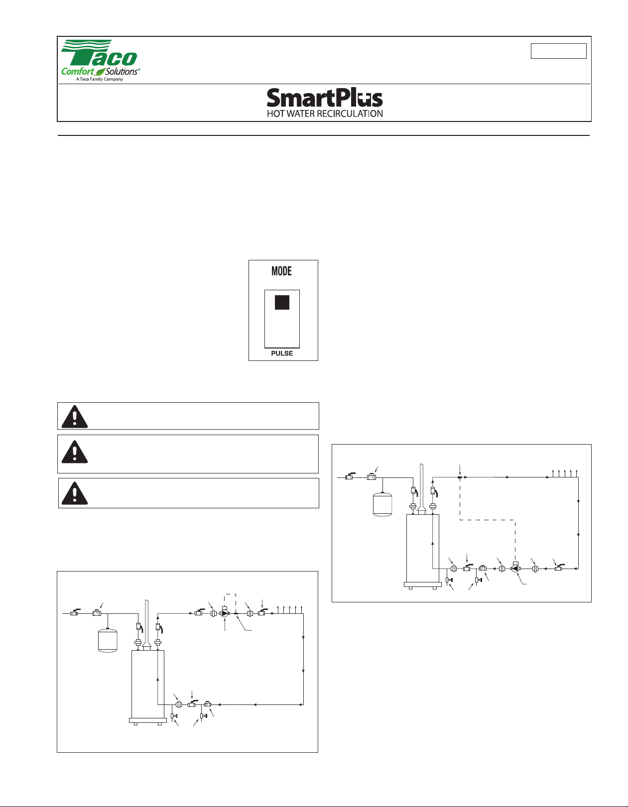
The SmartPlus has a “Mode Select” toggle switch that allows for 2 operation
modes. “Pulse” or “Smart” mode can be selected using the toggle switch
located on the electronic control board (see Figure 1). A yellow LED indicates
which mode is selected. All operation is automatic, no manual timer or temperature setting is required.
• “Pulse” Mode
When set for “Pulse” operation, the SmartPlus
will run for 1 to 10 minutes “ON” and 10 minutes
“OFF” to maintain hot water at all fixtures.
• See #5 Variable Run Time Setting on page 2.
• “Smart” Mode
When set for “Smart” operation, the SmartPlus
will run in “Pulse” mode as above for the first 7
days. During the first 7 days, the SmartPlus will
monitor and record the home’s hot water usage
pattern. For the next 7 days, the SmartPlus will
use the preceding week’s usage pattern to
Figure 1: Mode Select
cycle the pump. This process will be repeated every 7 days. The pump
will cycle for 1 hour before and after each recorded hot water demand.
WARNING: All local plumbing and electrical codes should be followed when installing this product.
WARNING: Risk of electrical shock. This pump is supplied with a
grounding conductor and grounding-type attachment plug. To
reduce the risk of shock, be certain that it is connected only to a
properly grounded grounding-type receptacle
.
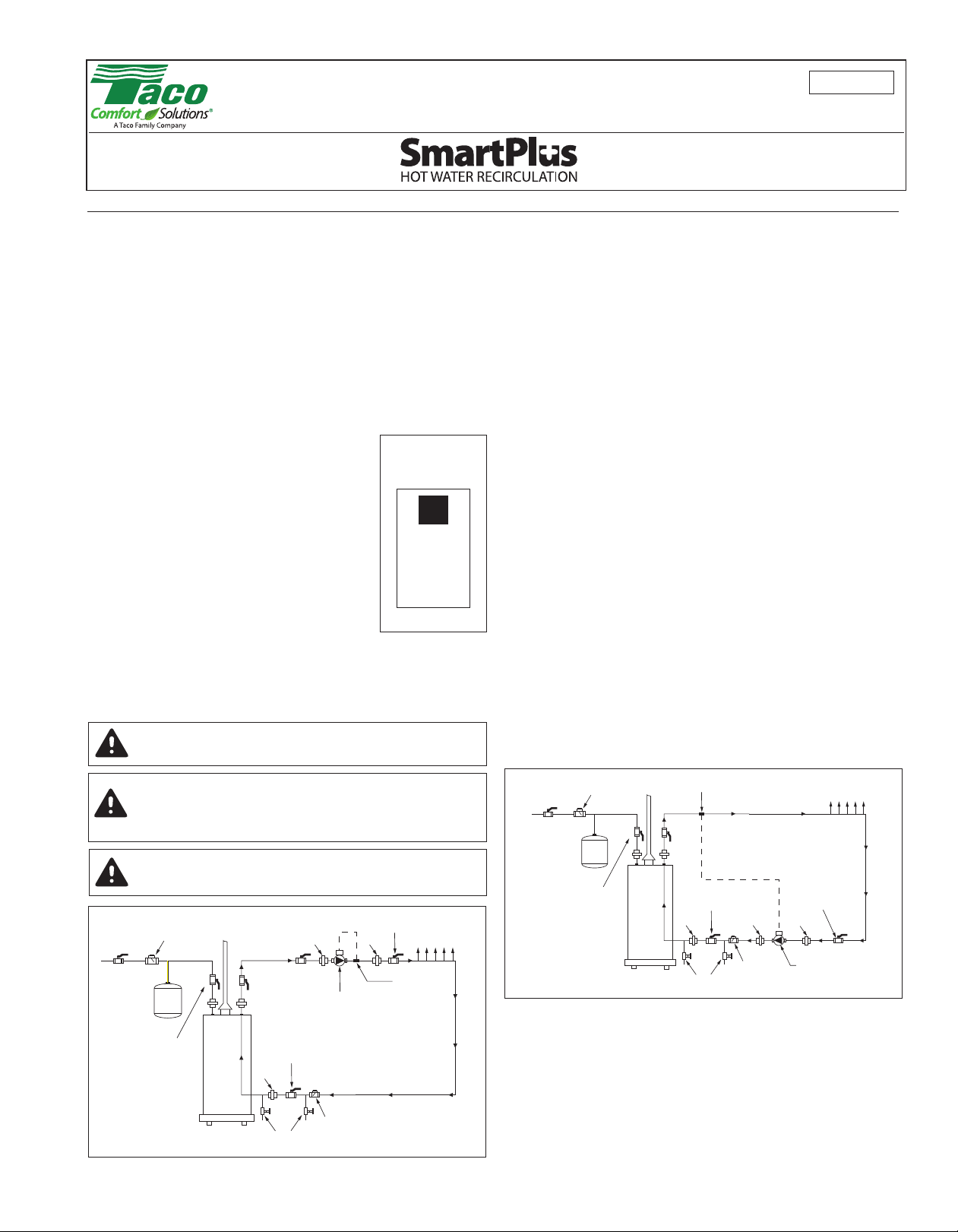
1. Install the SmartPlus in-line on the DHW supply line downstream of
the hot water source as shown in Figure 2. Be sure the directional
arrow on the casing is installed with the arrow pointing away from the
hot water source.
2. Install all other system components as shown in the piping diagram
in Figure 2.
3. When all components are installed, fill system with water.
4. Close the isolation valve on the return line between the water heater
and the flow check valve.
5. Open the drain valve between the isolation valve and flow check valve
and drain water until all air is purged from the line.
6. Close drain valve and open isolation valve.
7. The SmartPlus is shipped from the factory in “Smart” mode. To switch
the pump to “Pulse” mode, remove the 2 electrical box screws and
cover. Change the position of the toggle switch on the circuit board to
“Pulse” (see Figure 1). Replace the cover and secure with 2 screws.
8. Plug the external temperature sensor provided into the “TEMP SENSOR” receptacle on the side of the electrical box. Attach the sensor to
the hot water supply pipe downstream of the pump using the black ziptie connector provided. See Figure 2.
9. Once the system is filled and air is purged, plug in the SmartPlus
power cord.
NOTE:The temperature sensor must be installed and connected
in either “Pulse” or “Smart” mode.
NOTE: The SmartPlus must be installed and supported by the
circulation piping.
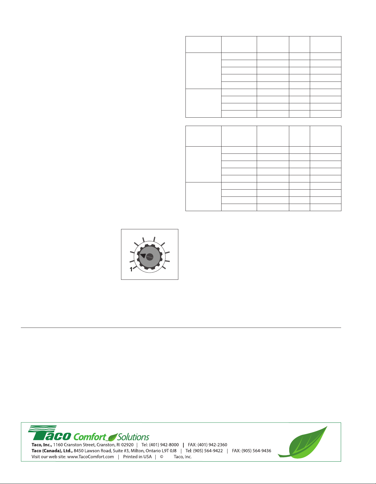
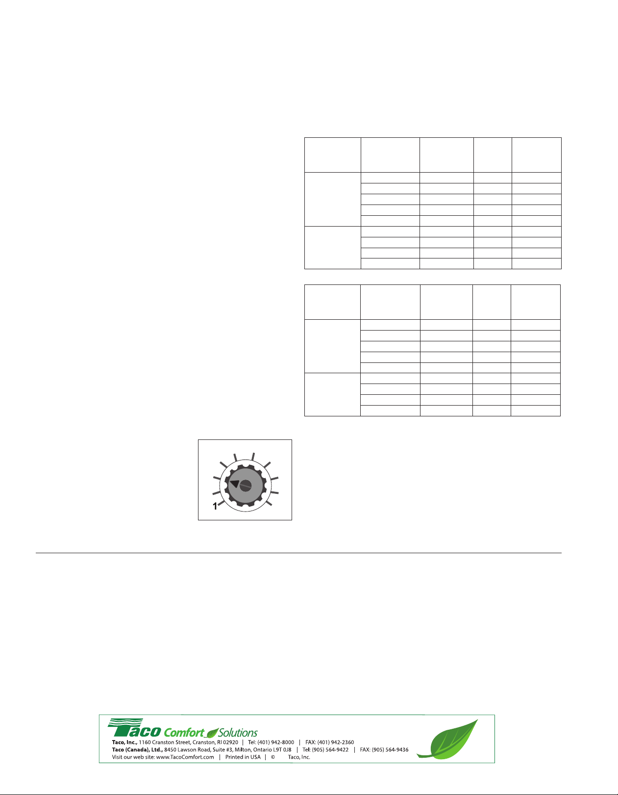
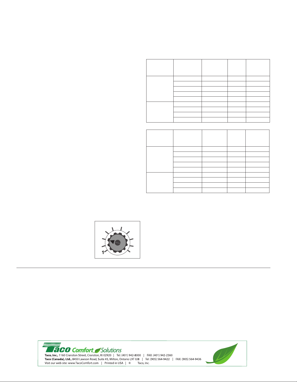
Hot Water Return Line (Option No. 2) - Install the SmartPlus on the
domestic hot water (DHW) return line pumping toward the DHW source.
The external sensor provided with the SmartPlus should be installed on
the DHW supply line. Refer to Figure 3 below.
CAUTION: Do not plug in the SmartPlus power cord until the system is filled with water and purged of air.
SUGGESTED PLUMBING INSTALLATION PROCEDURE:
Hot Water Supply Line (Option No. 1) - Install the SmartPlus on the
domestic hot water (DHW) supply line pumping away from the DHW
source. The external sensor provided with the SmartPlus should be
installed on the DHW supply line. Refer to Figure 2 below.
Option No. 1
Figure 2: Installation Diagram (For demonstration only)
Option No. 2
Figure 3: Installation Diagram (For demonstration only)
1. Install the SmartPlus in-line on the DHW return line as shown in
Figure 3. Be sure the directional arrow on the casing is installed with
the arrow pointing toward the hot water source.
2. Install all other system components as shown in the piping diagram in
Figure 3.
3. Follow steps 3 through 7 listed under the Hot Water Supply Line
(Option No. 1) section.
4. Plug the external temperature sensor provided into the “TEMP SENSOR” receptacle on the side of the electrical box. Attach the sensor to
the hot water supply pipe as in Figure 3, using the black zip-tie connector provided.
5. Once the system is filled and air is purged, plug in the SmartPlus
power cord.
NOTE:The temperature sensor provided may not have enough
wire length to reach the DHW supply pipe with the SmartPlus
Page 2
installed on the return line. In this case, standard low voltage
A Taco Family Company
2017
®
1
0
doorbell wire (not included) can be spliced into the sensor line
increasing the overall sensor wire length.
NOTE: The temperature sensor must be installed and connected
in either “Pulse” or “Smart” mode.
NOTE: The SmartPlus must be installed and supported by the
circulation piping.
OTHER SPECIAL FEATURES OF THE SMARTPLUS:
1. Vacation Function - If no water usage is detected for 36 hours, the
pump will remain off until hot water usage is detected. Once detected,
the pump will resume operation.
NOTE: If pump is set to “Smart” mode, the pump will operate in
“Pulse” mode for the first 7 days while recording usage patterns.
2. Exercise Function - While in vacation mode, the pump will come on
every 7 days for 10 seconds to prevent corrosion or scale buildup.
3. 72 Hour Memory Backup - Should a power outage occur, the
SmartPlus (in Smart mode only) will retain its recorded settings and
internal timer for 72 hours. When power is restored, the SmartPlus will
return to its programmed mode setting, either “Pulse” or “Smart.”
4. LED - The SmartPlus is provided with 3 LED’s located on the side of
the electrical box.
Green LED – Illuminated - Power On
Yellow LED – Flashing - Pump in “Pulse” mode
Illuminated (not flashing) - Pump in “Smart” mode
Red LED – LED off - Sensor is connected properly
LED flashes once every 5 seconds - Shorted sensor.
Use replacement sensor kit #194-3574.
LED flashes twice every 5 seconds - Open sensor
- check all sensor connections.
LED flashes three times every 5 seconds - Blown
fuse. Use replacement fuse kit #26-813RP.
5. Variable Run Time Setting - the Smart Plus run time can be set
for varying domestic hot water pipe sizes and loop length. The factory default setting is 3.
Follow the steps below to adjust the run
time:
1. Make sure the SmartPlus power
cord is unplugged from electrical outlet.
2. Remove the electrical box cover
from the circulator to expose the
electronic control board.
3. Adjust the run time dial using the
Pump Sizing and Dial Setting
guide. See Figure 4.
Figure 4: Run Time Dial
NOTE: For the best possible sys-
tem performance, some adjustments may need to be made to the dial position.
4. Replace the electrical box cover.
5. Plug SmartPlus power cord into electrical outlet. Pump will start
and run at the new run time setting.
Pump Sizing and Dial Setting Guide
/2″ Supply and Return Lines
1
upply Pipe
S
Model Number
06 & 006-IFC*
0
008 & 008-IFC*
3/4″ Supply and Return Lines
Model Number
006 & 006-IFC*
08 & 008-IFC*
0
Maximum
ength (ft.)
L
25 50 1 1/10
50 100 3 3/10
00
1
00
2
300 400 10 10/10
50
2
450 550 5 5/10
550 650 8 8/10
50
6
upply Pipe
S
Maximum
Length (ft.)
5
2
50 200 3 3/10
200 300 5 5/10
00
3
400 500 10 10/10
00
3
500 650 5 5/10
650 750 8 8/10
50
7
Total Maximum
ipe Length
P
00
2
00
3
50
4
00
7
otal
T
Maximum Pipe
ength
L
0
5
00
4
00
5
00
8
Dial
etting
S
5 5
8 8
3 3
0
1
Dial
Setting
1 1
8 8
3 3
0
1
ON/OFF Time
inutes
M
/10
/10
/10
0/10
1
ON/OFF Time
Minutes
/10
/10
/10
0/10
1
*With Optional Integral Flow Check
This information is provided as a reference only. Find the dial setting in the
guide above that best meets the design. Individual systems may vary.
Select the circulator model based on the supply and return pipe size and
pipeline length. Do not oversize the pump or high velocity noise and erosion corrosion of the system piping may result.
Sizing Assumptions:
Flow = 1GPM Max.
Velocity = 3 ft./sec.
Allowances have been added for pressure drop of other typical
system components.
Type L Copper Tubing
LIMITED WARRANTY STATEMENT
Taco, Inc. will repair or replace without charge (at the company’s
option) any product or part which is proven defective under normal use within three (3) years from the date of manufacture.
In order to obtain service under this warranty, it is the responsibility of the purchaser to promptly notify the local Taco stocking
distributor or Taco in writing and promptly deliver the subject
product or part, delivery prepaid, to the stocking distributor. For
assistance on warranty returns, the purchaser may either contact
the local Taco stocking distributor or Taco. If the subject product
or part contains no defect as covered in this warranty, the purchaser will be billed for parts and labor charges in effect at time
of factory examination and repair.
Any Taco product or part not installed or operated in conformity
with Taco instructions or which has been subject to misuse, misapplication, the addition of petroleum-based fluids or certain
chemical additives to the systems, or other abuse, will not be
covered by this warranty.
If in doubt as to whether a particular substance is suitable for use
with a Taco product or part, or for any application restrictions,
consult the applicable Taco instruction sheets or contact Taco at
[401-942-8000].
Taco reserves the right to provide replacement products and parts
which are substantially similar in design and functionally equivalent
to the defective product or part. Taco reserves the right to make
changes in details of design, construction, or arrangement of
materials of its products without notification.
TACO OFFERS THIS WARRANTY IN LIEU OF ALL OTHER
EXPRESS WARRANTIES. ANY WARRANTY IMPLIED BY LAW
INCLUDING WARRANTIES OF MERCHANTABILITY OR FITNESS IS IN EFFECT ONLY FOR THE DURATION OF THE
EXPRESS WARRANTY SET FORTH IN THE FIRST PARAGRAPH ABOVE.
THE ABOVE WARRANTIES ARE IN LIEU OF ALL OTHER
WARRANTIES, EXPRESS OR STATUTORY, OR ANY OTHER
WARRANTY OBLIGATION ON THE PART OF TACO.
TACO WILL NOT BE LIABLE FOR ANY SPECIAL, INCIDENTAL,
INDIRECT OR CONSEQUENTIAL DAMAGES RESULTING
FROM THE USE OF ITS PRODUCTS OR ANY INCIDENTAL
COSTS OF REMOVING OR REPLACING DEFECTIVE PRODUCTS.
This warranty gives the purchaser specific rights, and the purchaser may have other rights which vary from state to state.
Some states do not allow limitations on how long an implied warranty lasts or on the exclusion of incidental or consequential
damages, so these limitations or exclusions may not apply to
you.
Page 3
02-516
®
Válvula de
Contraujo
Tanque de
Expansión
Térmica
Grifos
Válvula de
Aislamiento
Conexión
Válvula de
Aislamiento
Conexión
Válvula de
Control
de Flujo
Válvula de
Drenado
Suministro de
Agua Caliente
Suministro
de Agua Fría
Retorno de Agua Caliente
Válvula de
Aislamiento
Válvula de
Aislamiento
Conexión Conexión
Válvula de
Aislamiento
LÍNEA DE SUMINISTRO
DE AGUA CALIENTE
(opción número 1)
Sensor de
Temperatura
Válvula de
Contraujo
Tanque de
Expansión
Térmica
Grifos
Válvula de
Aislamiento
Conexión
Válvula de
Aislamiento
Conexión
Válvula de
Control
de Flujo
Válvula de
Drenado
Suministro de
Agua Caliente
Suministro
de Agua Fría
Retorno de Agua Caliente
Válvula de
Aislamiento
Conexión
Conexión
LÍNEA DE RETORNO
DE AGUA CALIENTE
(opción número 2)
Sensor de
Temperatura
Válvula de
Aislamiento
1
Hoja de Instrucciones
Patent #: US 8,594,853
REMPLAZA A: 7 de abril de 2016 VIGENCIA: 23 de marzol de 2017
Número de identificación de planta: 001-4243
APLICACIÓN:
El sistema SmartPlus® de Taco está diseñado para incrementar el servicio
de agua caliente y conservar al mismo tiempo el agua y la energía. Al recircular el agua caliente “enfriada” hacia el calentador de agua, la espera por
agua caliente se reduce a segundos.
OPCIONES DE CONTROL DE LA BOMBA:
El SmartPlus tiene un selector de “selección de modo” que permite dos
modos de operación. Se puede seleccionar el modo “Pulso” o el modo
“Inteligente” con el selector ubicado en la tarjeta de control electrónico montada en la base del capacitor (consulte la Figura 1). Una luz LED amarilla indica el modo que está seleccionado. Toda la operación es automática; no se
requiere ajustar manualmente ni el temporizador ni la temperatura.
• Modo de “Pulso”
Cuando se establece para la operación "Pulse",
el SmartPlus tendrá una duración de 1 a 10 minutos "ON" y 10 minu-tos "OFF" para mantener el
agua caliente en todos los aparatos.
• Consulte # 5 Ajuste del tiempo de funcionamiento
variable en la página 2.
• Modo “Inteligente/Memoria”
Cuando se le ajusta para operación
“Inteligente/memoria”, el SmartPlus funcionará en
el modo “Pulso” como se indicó anteriormente
durante los primeros siete días. Durante estos
primeros siete días, el SmartPlus monitoreará y
Figura 1:
Selección de modo
registrará el patrón de uso del agua caliente del hogar. Durante los siete
días siguientes, el SmartPlus usará el patrón de uso de la semana anterior para establecer el ciclo la bomba. Este proceso se repetirá cada
siete días. La bomba funcionará en modo “Pulso” desde una hora antes
hasta una hora después de cada demanda de agua caliente registrada.
ADVERTENCIA: Se deben aplicar todos los códigos locales de
plomería y eléctricos al instalar este producto.
ADVERTENCIA: Existe riesgo de descarga eléctrica. La bomba
se entrega con un conductor de conexión a tierra y un enchufe
preparado para conexión a tierra. Para reducir el riesgo de
descarga eléctrica, asegúrese de conectarlo en un tomacorri
ente pre- parado para conexión a tierra y que esté debidamente aterrizado.
1. Instale el SmartPlus en línea en la línea de suministro de ACS aguas
abajo de la fuente de agua caliente como se muestra en la Figura 2.
Asegúrese de que la flecha direccional en la carcasa esté instalada
con la flecha apuntando lejos de la fuente de agua caliente.
2. Instale todos los demás componentes del sistema como se muestra
en el diagrama de tuberías de la Figura 2.
3. Una vez que todos los componentes estén instalados llene el sistema con agua.
4. Cierre la válvula de aislamiento ubicada en la línea de retorno entre
el calentador de agua y la válvula de control de flujo (vea la Figura 2).
5. Abra la válvula de drenado y drene el agua hasta que el aire se purgue de la línea.
6. Cierre la válvula de drenado y abra la válvula de aislamiento.
7. El SmartPlus se envía de la fábrica en modo “Inteligente”. Para cambiar la bomba a modo “Pulso”, retire los dos tornillos de la tapa del
capacitor y quítela. Cambie la posición del selector en la tarjeta de
circuito a “Pulso” (vea la Figura 1). Reinstale la tapa del capacitor y
fíjela con los dos tornillos.
8. Conecte el sensor de temperatura externo incluido en el receptáculo
“TEMP SENSOR” ubicado a un lado de la base del capacitor. Conecte
el sensor en la línea de suministro de agua caliente corriente abajo de
la bomba usando el conector negro de cinta de cierre suministrada.
Vea la Figura 2.
9. Enchufe el cordón eléctrico del SmartPLus cuando el sistema esté
lleno de agua y el aire se haya purgado.
NOTA: El sensor de temperatura debe instalarse y conectarse ya
sea en el modo “Pulso” o “Inteligente”.
NOTA: El SmartPlus debe quedar instalado en, y ser soportado
por, la tubería de circulación.
Línea de Retorno de Agua Caliente (Opción No. 2) - Instale el
SmartPlus en la tubería de retorno de agua caliente sanitaria (DHW) hacia
la fuente de agua caliente sanitaria. El sensor externo suministrado con el
SmartPlus debe instalarse en la línea de suministro de agua caliente sanitaria. Consulte la Figura 3 a continuación.
PRECAUCIÓN: No enchufe el cordón eléctrico del Smart-Plus
hasta que el sistema se haya llenado con agua y el aire se haya
purgado.
PROCEDIMIENTO SUGERIDO DE INSTALACIÓN DE LA TUBERÍA:
Línea de Suministro de Agua Caliente (Opción No. 1) - Instale el
SmartPlus en la línea de suministro de agua caliente doméstica con el
bombeo en dirección contraria a la fuente del agua caliente doméstica. El
sensor externo que se proporciona con el SmartPlus debe instalarse en la
línea de suministro del agua caliente doméstica. Consulte la Figura 2 a
continuación.
Opción No. 1
Figura 2: Diagrama de instalación (solamente para la explicación)
Opción No. 2
Figura 3: Diagrama de instalación (solamente para la explicación)
1. Instale el SmartPlus en línea en la línea de retorno de agua sanitaria
como se muestra en la Figura 3. Asegúrese de que la flecha direccional en la carcasa esté instalada con la flecha apuntando hacia la
fuente de agua caliente.
2. Instale todos los demás componentes del sistema como se muestra en
el diagrama de tuberías de la Figura 3.
3. Siga los pasos 3 a 7 enumerados en la sección Línea de suministro de
agua caliente (Opción No. 1).
4. Enchufe el sensor de temperatura externo suministrado en el receptáculo "TEMP SENSOR" situado en el lateral de la caja eléctrica.
Conecte el sensor a la tubería de suministro de agua caliente utilizando el conector de cremallera negro suministrado.
5. Una vez que el sistema esté lleno y el aire sea purgado, enchufe el
cable de alimentación SmartPlus.
Page 4
NOTA: El alambre del sensor de temperatura suministrado puede
A Taco Family Company
2017
®
1
0
no ser lo suficientemente largo para alcanzar la línea de suministro
del agua caliente doméstica con el SmartPlus instalado en la línea
de retorno. En este caso, se puede empalmar alambre estándar de
bajo voltaje (no incluido) para timbre de puerta con el alambre del
sensor pata aumentar su longitud total.
NOTA: El sensor de temperatura debe instalarse y conectarse ya
sea en el modo “Pulso” o “Inteligente”.
NOTA: El SmartPlus debe quedar instalado en, y ser soportado
por, la tubería de circulación.
OTRAS CARACTERÍSTICAS ESPECIALES DEL SMARTPLUS:
1. Función de vacaciones - Si no se detecta el uso de agua durante
36 horas, la bomba permanecerá apagada hasta que se detecte el
uso de agua caliente. Una vez detectada, la bomba reanudará su funcionamiento.
NOTA: Si la bomba está ajustada en el modo "Smart", la bomba fun-
cionará en modo "Pulso" durante los primeros 7 días mientras graba
los patrones de uso.
2. Función de Ejercicio - Durante el modo de vacaciones, la bomba se
encenderá cada 7 días durante 10 segundos para evitar la corrosión o
acumulación de incrustaciones.
3. Respaldo de la memoria de 72 horas - En caso de que se produzca
un corte de energía, el SmartPlus (sólo en el modo inteligente) conservará los ajustes grabados y el temporizador interno durante 72
horas. Cuando se restablece la alimentación, el SmartPlus volverá a
su configuración de modo programado, ya sea "Pulse" o "Smart".
4. LED - El SmartPlus está provisto de 3 LED situados en el lateral de
la caja eléctrica.
LED verde - Iluminado - Encendido
LED amarillo - Intermitente - bomba en el modo de "Pulse"
Iluminado (sin parpadear) - Bomba en modo "inteligente"
LED rojo - LED apagado - El sensor está conectado correctamente
LED parpadea una vez cada 5 segundos - Acortar el sensor.
Utilice el kit de reemplazo del sensor # 194-3574.
LED parpadea dos veces cada 5 segundos - Sensor abierto.
LED parpadea tres veces cada 5 segundos - Fusible fundido.
Usar fusible de repuesto kit # 26-813RP.
5. Configuración de tiempo de funcionamiento variable: el tiempo
de funcionamiento de Smart Plus puede ajustarse para variar el
tamaño de los tubos de agua caliente sanitaria y la longitud del bucle.
El ajuste predeterminado de fábrica es 3.
Siga los pasos a continuación para ajustar
el tiempo de ejecución:
1. Asegúrese de que el cable de alimentación SmartPlus esté desenchufado del tomacorriente.
2. Retire la cubierta de la caja eléctrica
del circulador para exponer la tarjeta
electrónica de control.
3. Ajuste el dial de tiempo de funcionamiento mediante la guía de configuración de calibrado y marcado de la
bomba. Vea la Figura 4.
Dial de tiempo de ejecución
Figura 4:
NOTA: Para obtener el mejor rendimiento posible del sistema, es
posible que sea necesario realizar algunos ajustes en la posición
de marcado.
4. Vuelva a colocar la cubierta de la caja eléctrica.
5. Conecte el cable de alimentación SmartPlus al enchufe eléctrico. La
bomba comenzará y funcionará con el nuevo ajuste de tiempo de funcionamiento.
Guía de configuración del dimensionado y marcación de la bomba:
1/2" Líneas de suministro y retorno
uministro de
Número de
odelo
m
006 & 006-IFC*
08 & 008-IFC*
0
3/4″ Supply and Return Lines
Número de
modelo
006 & 006-IFC*
008 & 008-IFC*
*Con flujo opcional Comprobar Integral
S
tuberías
ongitud
L
máxima (ft.)
5
2
50 100 3 3/10
100 200 5 5/10
200 300 8 8/10
300 400 10 10/10
50
2
50
4
50
5
650 700 10 10/10
uministro de
S
tuberías
ongitud
L
máxima (ft.)
25 50 1 1/10
50 200 3 3/10
200 300 5 5/10
300 400 8 8/10
400 500 10 10/10
300 500 3 3/10
500 650 5 5/10
650 750 8 8/10
750 800 10 10/10
ongitud total
L
áxima del
m
conducto
0
5
50
4
50
5
50
6
Longitud total
áxima del
m
conducto
Ajuste del
ial
d
1 1
3 3
5 5
8 8
Ajuste del
ial
d
N / OFF
O
iempo
T
Minutos
/10
/10
/10
/10
ON / OFF
iempo
T
Minutos
Esta información se sirve únicamente como una guía. Encontrar el ajuste
en el cuadro anterior que mejor cumpla con el diseño. Los sistemas individuales pueden variar. Seleccione el modelo de circulación basado en el
suministro y el volumen de la tubería y la longitud de la tubería. No sobredimensionar la bomba o el ruido de alta velocidad y la corrosión por la
erosión de las tuberías del sistema puede resultar.
Aupuestos:
Flujo = 1GPM Max.
Velocidad = 3 ft./sec.
Los derechos de emisión se han añadido para la caída de presión de
otros componentes típicos del sistema.
De tipo L Tubería de cobre.
GARANTÍA LIMITADA
Taco, Inc. reparará o reemplazará sin cargo (a elección de la
empresa) cualquier producto o pieza que se estén defectuosos
bajo uso normal dentro de los tres (3) años desde la fecha de
fabricación.
Para obtener servicio al amparo de esta garantía, el comprador
tiene la responsabilidad de notificar por escrito y con prontitud al distribuidor local de productos Taco o a Taco y entregar con prontitud
el producto o pieza en cuestión, con entrega pre-pagada, al distribuidor del producto. Para asistencia en devoluciones de garantía,
el comprador puede comunicarse con el distribuidor local de productos Taco o con Taco. Si el producto o pieza en cuestión no contiene defectos cubiertos por esta garantía, se facturará al comprador por las piezas y costos de mano de obra vigentes en el
momento de la inspección y reparación en la fábrica.
Cualquier producto Taco no instalado u operado según las
instrucciones de Taco o que haya sido sometido a mal uso, aplicación errónea, a la adición de fluidos a base de petróleo o de
ciertos aditivos químicos a los sistemas, o a otro tipo de abuso,
no estará cubierto por esta garantía.
Si tiene dudas acerca de si una sustancia en particular es adecuada para usarse con un producto o pieza Taco, o acerca de
cualquier restricción en la aplicación, consulte las instrucciones
correspondientes de Taco o llame a Taco al teléfono [401-9428000].
Taco se reserva el derecho de proporcionar productos y piezas
de remplazo que sean sustancialmente similares en diseño y
equivalentes en funcionalidad al producto o pieza defectuosa.
Taco se reserva el derecho de hacer cambios a los detalles del
diseño, construcción o configuración de materiales de sus productos sin notificación.
TACO OFRECE ESTA GARANTÍA COMO REEMPLAZO DE
TODAS LAS DEMÁS GARANTÍAS EXPRESAS. CUALQUIER
GARANTÍA IMPLÍCITA POR LEY, INCLUYENDO GARANTÍAS DE
COMERCIABILIDAD O IDONEIDAD, TIENE EFECTO SOLA-
MENTE DURANTE EL PERIODO DE LA GARANTÍA EXPRESA
ESTABLECIDA EN EL PRIMER PÁRRAFO MÁS ARRIBA.
LAS GARANTÍAS ANTERIORES REMPLAZAN A TODAS LAS
DEMÁS GARANTÍAS, EXPRESAS O DE LEY, O A CUALQUIER
OTRA OBLIGACIÓN DE GARANTÍA DE PARTE DE TACO.
TACO NO SERÁ RESPONSABLE DE NINGÚN DAÑO ESPECIAL,
INCIDENTAL, INDIRECTO O CONSECUENTE QUE RESULTE
DEL USO DE SUS PRODUCTOS O DE CUALQUIER COSTO INCIDENTAL DE REMOVER O REMPLAZAR PRODUCTOS DEFECTUOSOS.
Esta garantía da al comprador derechos específicos y el comprador puede tener otros derechos que varían de un estado a otro.
Algunos estados no permiten limitaciones sobre cuánto dura una
garantía implícita o sobre la exclusión de daños incidentales o consecuentes, de modo que esas limitaciones o exclusiones podrían
no ser aplicables para usted.
Page 5
102-516
Dispositif
anti-refoulement
Réservoir
d'expansion
thermique
Appareil
sanitaire
Robinet
d'isolement
Raccord
Robinet
d'isolement
Raccord
Clapet
anti-retour
Robinet
de purge
Alimentation
en eau chaude
Alimentation
en eau froide
Retour d'eau chaude
Robinet
d'isolement
Robinet
d'isolement
Raccord Raccord
Robinet
d'isolement
LIGNE D'ALIMENTATION
EN EAU CHAUDE
Sonde de
température
MODE
IMPULSION
INTELLIGENT
®
Dispositif
anti-refoulement
Réservoir
d'expansion
thermique
S
onde de
température
Appareil
sanitaire
Robinet
d'isolement
Raccord
Robinet
d'isolement
Raccord
Clapet
anti-retour
Robinet
de purge
Robinet
d'isolement
Alimentation
en eau chaude
Alimentation
en eau froide
Retour d'eau chaude
Robinet
d'isolement
Raccord
Raccord
LIGNE DE RETOUR
D'EAU CHAUDE
Feuillet d’instruction
Patent #: US 8,594,853
REVISION: 7 avril 2016 PUBLICATION: 23 mars 2017
Installation ID# 001-4243
APPLICATION :
Le SmartPlus® de Taco est conçu pour accroître votre confort en eau
chaude tout en économisant de l'eau et de l'énergie. En recyclant l'eau
chaude "refroidie" vers votre chauffe-eau, le temps d'attente pour obtenir
de l'eau chaude est réduit à quelques secondes.
OPTIONS DE COMMANDE DE LA POMPE :
Le SmartPlus possède un interrupteur à bascule "Mode Select" (Sélection
de mode) qui offre 2 modes de fonctionnement. On sélectionne le mode
"Pulse" (Impulsion) ou le mode "Smart" (Intelligent) à l’aide de l'interrupteur
à bascule situé sur la carte de commande électronique montée sur l'embase du condensateur (voir Figure 1). Un voyant lumineux jaune indique le
mode sélectionné. Toutes les opérations sont automatiques : aucun minuteur manuel ou réglage de température n'est nécessaire.
• Mode "Pulse" (Impulsion)
En mode "Pulse", le SmartPlus fonctionnera
pendant 1 à 10 minutes "ON" et à 10 minutes
"OFF" pour maintenir l'eau chaude à tous les
appareils.
• Voir # 5 Réglage du temps d'exécution variable
à la page 2.
• Mode"Smart/Learn" (Intelligent/Acquisition)
En mode "Smart/Learn", le SmartPlus se met
en route en mode "Pulse" comme ci-dessus
pendant les 7 premiers jours. Pendant les 7
premiers jours, le SmartPlus surveillera et
créera un enregistrement du modèle d'utilisation de l'eau chaude de votre habitation.
Pendant les 7 jours suivants, le SmartPlus
utilisera alors le modèle d'utilisation de la
Figure 1: Mode de
sélection
semaine passée pour commander le cycle de
pompage. Ce processus sera répété tous les 7 jours. La pompe se
met en route en mode "Pulse" 1 heure avant et 1 heure après chaque
demande en eau chaude enregistrée.
AVERTISSEMENT : tous les repères électriques et de la tuyauterie
locale doivent être pris en compte lors de l'installation de ce produit.
AVERTISSEMENT : risque de décharge électrique. Cette pompe
est munie d'un conducteur de mise à la terre et d'une prise de
raccordement à la terre. Pour éviter tout risque d'électrocution,
veuillez être certain qu'elle soit branchée exclusivement à une
prise de terre, correctement mise à la terre.
ATTENTION : ne pas brancher le cordon d'alimentation du
SmartPlus tant que le circuit n'a pas été rempli d'eau et que l'air
n'a pas été purgé
.
PROCEDURE RECOMMANDÉE D'INSTALLATION DE LA TUYAUTERIE :
Ligne d'alimentation en eau chaude (Option N°1) - installez le SmartPlus
sur le pompage de la ligne d'alimentation en eau chaude sanitaire (ECS)
loin de la source ECS. La sonde externe fournie avec le SmartPlus doit être
installée sur la ligne d'alimentation ECS. Consultez la Figure 2.
1. Installez le SmartPlus en ligne sur la ligne d'alimentation en eau
chaude en aval de la source d'eau chaude comme le montre la Figure
2. Assurez-vous que la flèche directionnelle sur le boîtier est installée
avec la flèche pointant loin de la source d'eau chaude.
2. Installez tous les autres composants du système comme indiqué dans
le diagramme de tuyauterie de la Figure 2.
3. Quand tous les composants sont installés, remplissez le circuit d'eau.
4. Fermez le robinet d'isolement sur la ligne de retour entre le chauffe-eau
et le clapet anti-retour (voir Figure 2).
5. Ouvrez le robinet de purge et laissez écouler l'eau tant que de l'air est
présent dans la conduite.
6. Fermez le robinet de purge et ouvrez le robinet d'isolement.
7. Le SmartPlus est configuré par défaut en mode "Smart" en usine.
Pour basculer en mode "Pulse", retirez les 2 vis du couvercle du condensateur et le couvercle. Placez l'interrupteur à bascule en position
"Pulse" sur la carte de commande (voir Figure 1). Remontez le couvercle du condensateur et serrez les 2 vis.
8. Branchez la sonde de température externe fournie à la prise "TEMP
SENSOR" (Sonde de température) sur le côté de l'embase du condensateur. Fixez le capteur sur la conduite d'alimentation en eau chaude
en aval de la pompe en utilisant l'attache rapide noire fournie.
9. Une fois le circuit rempli et l'air purgé, branchez le cordon d'alimentation du SmartPlus.
REMARQUE : la sonde de température doit être installée et
branchée dans les deux modes "Pulse" ou "Smart".
REMARQUE : le SmartPlus doit être installé et pris en charge par
la tuyauterie de circulation.
Ligne de retour d'eau chaude (Option N° 2) - Installez le SmartPlus sur
le tuyau de retour d'eau chaude sanitaire (ECS) vers la source d'ECS. Le
capteur externe fourni avec le SmartPlus doit être installé sur la ligne d'alimentation en eau chaude sanitaire. Reportez-vous à la Figure 3 ci-dessous.
Option N° 1
Figure 2: Schéma d'installation (Pour la démonstration seulement)
Option N° 2
Figure 3: Schéma d'installation (Pour la démonstration seulement)
1. Installez le SmartPlus en ligne sur la ligne de retour d'eau chaude sanitaire comme indiqué sur la Figure 3. Assurez-vous que la flèche directionnelle sur le boîtier est installée avec la flèche pointant vers la source
d'eau chaude.
2. Installez tous les autres composants du système comme indiqué dans le
diagramme de tuyauterie de la Figure 3.
3. Suivez les étapes 3 à 7 énumérées sous la section Ligne d'alimentation
en eau chaude (Option N° 1).
4. Branchez le capteur de température externe fourni dans la prise «TEMP
SENSOR» sur le côté de la boîte électrique. Fixez le capteur au tuyau
d'alimentation en eau chaude à l'aide du connecteur noir fourni.
Page 6
5. Une fois le système rempli et purgé l'air, branchez le cordon d'alimenta-
A Taco Family Company
2017
®
1
0
tion SmartPlus.
REMARQUE: Le capteur de température fourni peut ne pas avoir
la longueur de câble suffisante pour atteindre le tuyau d'alimentation d'ECS avec le SmartPlus installé sur la ligne de retour.
Dans ce cas, le fil standard de la sonnette basse tension (non
inclus) peut être épissé dans la ligne de capteur augmentant la
longueur globale du fil de capteur.
REMARQUE: Le capteur de température doit être installé et
branché en mode "Impulsion" ou "Smart".
REMARQUE: Le SmartPlus doit être installé et soutenu par la
tuyauterie de circulation.
AUTRES CARACTERISTIQUES SPECIALES DU SMARTPLUS :
1. Fonction Vacances - si aucune consommation d'eau n'est détectée
pendant 36 heures, la pompe reste éteinte tant que l'eau chaude n'est
pas utilisée. Si l'eau chaude est utilisée, la pompe se remet en route.
REMARQUE : si la pompe est en mode "Smart", elle fonctionne en
mode "Pulse" pendant les 7 premiers jours afin de créer l'enregistrement du modèle d'utilisation.
2. Fonction d'exercice - En mode vacances, la pompe s'allume tous les
7 jours pendant 10 secondes pour éviter la corrosion ou l'accumulation
d'écailles.
3. Sauvegarde de la mémoire de 72 heures - En cas de panne de
courant, le SmartPlus (en mode Smart uniquement) conserve ses
réglages enregistrés et sa minuterie interne pendant 72 heures.
Lorsque le courant est rétabli, le SmartPlus revient à son mode de programmation programmé, soit «Pulse» ou «Smart».
4. LED - Le SmartPlus est fourni avec 3 de LED située sur le côté de la
boîte électrique.
LED verte - Illumination - Power On
LED jaune - Clignotant - pompe en mode "Pulse"
Illumination (ne clignote pas) - pompe en mode "Smart"
LED rouge - DEL éteinte - Le capteur est correctement connecté
LED clignote une fois toutes les 5 secondes - Capteur shorted.
Utilisez kit capteur de remplacement #194-3574.
LED clignote deux fois toutes les 5 secondes - capteur ouvert
LED clignote trois fois toutes les 5 secondes - Fusible grillé. Utilisez le
fusible de remplacement kit #26-813RP.
5. Réglage du temps de fonctionnement variable - le temps de fonc-
tionnement Smart Plus peut être réglé pour varier la taille des tuyaux
d'eau chaude sanitaire et la longueur de la boucle. Le réglage par
défaut est 3.boucle.
Suivez les étapes ci-dessous pour régler le run time:
1. Assurez-vous que le cordon d'alimentation SmartPlus est débranché de la
prise électrique.
2. Retirez le couvercle de la boîte électrique du circulateur pour exposer la
carte électronique de commande.
3. Réglez le cadran de temps d'exécution à l'aide du guide Réglage de la taille
de la pompe et du cadran. Voir figure 4.
Figure 4: Compteur horaire
REMARQUE: Pour obtenir les meilleures performances posibles du
sytème,il peut être nécessaire d'effectuer certains ajustements à la
position du sélecteur.
4. Remettre le couvercle de la boîte électrique.
5. Branchez le cordon d'alimentation SmartPlus dans une prise électrique. La pompe démarre et fonctionne au nouveau paramètre d'exécution.
Guide de Paramétrage de la Dimension de la Pompe et du Cadran
1/2" lignes d'alimentation et de retour
uyau
Numéro de
odèle
m
006 & 006-IFC*
08 & 008-IFC*
0
/4″ Alimentation et de Retour
3
uméro de
N
odèle
m
006 & 006-IFC*
008 & 008-IFC*
*Avec option Integral débit Vérifier
Ces informations sont fournies uniquement à titre indicatif. Trouver le paramètre dans
le guider ci-dessus qui répond le mieux design. Les systèmes individuels varient.
Sélectionnez le modèle de circulation en fonction de l'offre et retour la taille du tuyau
et la longueur du tuyau. Ne pas surdimensionner la pompe ou du bruit à haute vitesse
et de l'érosion corrosion du système de tuyauterie peut entraîner.
Hypothèses:
Débit = 1 GPM Max.
Débit = 3 ft./sec.
Les allocations ont été ajoutés à la chute de pression des autres composants
du système typiques.
L Type de tube de cuivre.
T
d'alimentation
ongueur
l
aximum (ft.)
M
5
2
0
5
100 200 5 5/10
200 300 8 8/10
300 400 10 10/10
250 450 3 3/10
50
4
50
5
650 700 10 10/10
Tuyau
'alimentation
d
longueur
aximum (ft.)
M
5
2
0
5
200 300 5 5/10
300 400 8 8/10
400 500 10 10/10
300 500 3 3/10
500 650 5 5/10
650 750 8 8/10
750 800 10 10/10
ongueur max-
L
imale totale
u conducteur
d
0
5
00
1
50
5
50
6
Longueur
aximale
m
totale du
onducteur
c
0
5
00
2
Réglage
u cadran
d
1 1
3 3
5 5
8 8
églage
R
du cadran
1 1
3 3
ON / OFF
emps
T
procès-verbal
/10
/10
/10
/10
ON / OFF
Temps
rocès-verbal
p
/10
/10
DECLARATION DE GARANTIE LIMITEE
Taco, Inc. réparera ou remplacera sans frais (au choix de l'entreprise) tout produit ou pièce qui est prouvé défectueux sous utilisation normale dans les trois (3) ans à compter de la date de fabrication.
Afin d'obtenir la réparation sous cette garantie, il incombe à l'acheteur d'aviser rapidement le distributeur Taco local ou la
société Taco par écrit et d'envoyer sans délai la pièce ou le produit concerné, en port payé, au distributeur. Pour obtenir de
l'aide à propos des retours en garantie, l'acheteur peut soit contacter le distributeur Taco local, soit la société Taco. Si le produit
ou la pièce concernée ne contient aucun défaut couvert par cette
garantie, l'acheteur se verra facturer le coût de la main d’œuvre
et des pièces en vigueur au moment de l'examen et la réparation
en usine.
Tout pièce ou produit Taco non installé ou utilisé conformément
aux instructions données par Taco ou qui a été soumis à une
mauvaise utilisation, à une utilisation détournée, à l'ajout de liquides à base de pétrole ou de certains additifs chimiques dans les
circuits, ou tout autre abus, ne sera pas couvert par cette garantie.
En cas de doute à propos de l'utilisation appropriée d’une substance particulière avec les pièces ou les produits Taco, ou pour
toutes restrictions d'utilisation, consultez les feuillets d'instruction
Taco concernés ou contactez Taco par téléphone au [401-9428000].
Taco se réserve le droit de fournir des pièces ou des produits de
rechange dont la conception est substantiellement similaire ou
de fonction équivalente pour remplacer la pièce ou le produit
défectueux. Taco se réserve le droit d'apporter toutes modifications dans les détails de la conception, la fabrication ou la disposition de ses produits sans préavis.
TACO ACCORDE CETTE GARANTIE EN REMPLACEMENT DE
TOUTE AUTRE GARANTIE EXPRESSE. TOUTE GARANTIE
IMPLICITE LEGALE, Y COMPRIS LES GARANTIES DE
VALEUR MARCHANDE OU D'ADEQUATION, EST EN
VIGUEUR EXCLUSIVEMENT POUR LA DUREE DE LA
GARANTIE EXPRESSE ENONCEE DANS L'ALINEA PREMIER.
LES GARANTIES CI-DESSUS REMPLACENT TOUTES LES
AUTRES GARANTIES, EXPRESSES OU LEGALES, OU
TOUTE AUTRE OBLIGATION DE GARANTIE DE LA PART DE
LA SOCIETE TACO.
TACO NE SERA PAS TENU RESPONSABLE DES DOMMAGES
SPECIAUX, ACCESSOIRES, INDIRECTS OU CONSECUTIFS
RESULTANT DE L'UTILISATION DE SES PRODUITS OU DES
COUTS ACCESSOIRES DE REMPLACEMENT OU DE
DEMONTAGE DES PRODUITS DEFECTUEUX.
De cette garantie découlent des droits particuliers pour l'acheteur,
et l'acheteur peut avoir d'autres droits qui varient selon les pays.
Certains pays ne fixent pas de limites à la durée d'une garantie
implicite ou à l'exclusion des dommages fortuits ou consécutifs. Par
conséquent, ces limites ou exclusions peuvent ne pas s'appliquer
à vous.
 Loading...