

Page 1
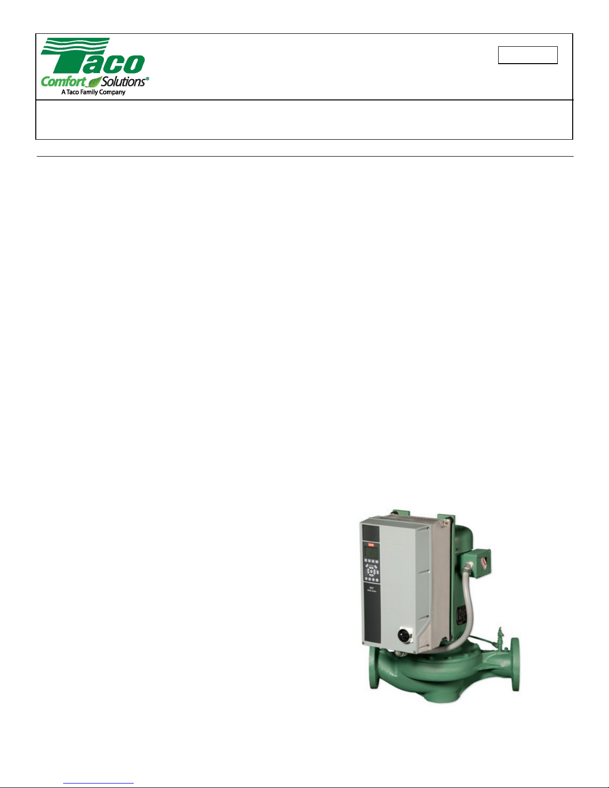
SKV SelfSensing
Vertical In-line Pump
Installation, Operation, and Maintenance Manual
302-365
SUPERSEDES: January 14, 2014
Plant ID: 001-4208
Table of Contents
1 SAFETY REQUIREMENTS. . . . . . . . . . . . . . . . . . . . 2
2 GENERAL INSTALLATION REQUIREMENTS. . . . . 2
2.1 Receiving Pump. . . . . . . . . . . . . . . . . . . . . . . . . 2
2.2 Location . . . . . . . . . . . . . . . . . . . . . . . . . . . . . . . 2
2.3 Foundation . . . . . . . . . . . . . . . . . . . . . . . . . . . . . 2
3 MAINTENANCE . . . . . . . . . . . . . . . . . . . . . . . . . . . . 2
3.1 Routine Inspections . . . . . . . . . . . . . . . . . . . . . . 2
3.2 Close Coupled Pumps . . . . . . . . . . . . . . . . . . . .3
3.3 Close Coupled Motors . . . . . . . . . . . . . . . . . . . . 3
3.4 Mechanical Seal. . . . . . . . . . . . . . . . . . . . . . . . . 3
4 DIS-ASSEMBLY AND RE-ASSEMBLY. . . . . . . . . . . 3
4.1 General . . . . . . . . . . . . . . . . . . . . . . . . . . . . . . .3
4.2 Dis-Assembly . . . . . . . . . . . . . . . . . . . . . . . . . . . 3
4.3 Re-Assembly . . . . . . . . . . . . . . . . . . . . . . . . . . . 3
5 PUMP PIPING - GENERAL. . . . . . . . . . . . . . . . . . . . 4
6 APPLICATION. . . . . . . . . . . . . . . . . . . . . . . . . . . . . . 4
7 MECHANICAL INSTALLATION . . . . . . . . . . . . . . . . 4
7.1 Location . . . . . . . . . . . . . . . . . . . . . . . . . . . . . . . 4
7.2 VFD Mounting to Pump . . . . . . . . . . . . . . . . . . . 4
7.3 VFD Mounting to Wall . . . . . . . . . . . . . . . . . . . . 6
7.4 Pump Piping – Detailed . . . . . . . . . . . . . . . . . . . 6
8 ELECTRICAL CONNECTIONS. . . . . . . . . . . . . . . . . 9
8.1 Exploded Views . . . . . . . . . . . . . . . . . . . . . . . . . 9
8.2 Electrical Installation . . . . . . . . . . . . . . . . . . . .10
8.3 Grounding Requirements. . . . . . . . . . . . . . . . . 12
8.4 Typical Terminal Wiring Configurations . . . . . .18
9 USER INTERFACE . . . . . . . . . . . . . . . . . . . . . . . . . 28
9.1 Local Control Panel . . . . . . . . . . . . . . . . . . . . . 28
9.2 Backup and Copying Parameter Settings . . . . 30
9.3 Password Protection . . . . . . . . . . . . . . . . . . . . 31
10 PUMP CONTROL SET-UPS . . . . . . . . . . . . . . . . . 34
10.1 SelfSensing Description. . . . . . . . . . . . . . . . . 34
10.2 Set-up Menu . . . . . . . . . . . . . . . . . . . . . . . . . 34
10.3 Variable Flow Control (Flow Compensation) . 35
10.4 Constant Flow Control . . . . . . . . . . . . . . . . . . 35
10.5 Constant Pressure Control. . . . . . . . . . . . . . . 36
10.6 Sequencing (Standby Pump Alternation). . . . 36
EFFECTIVE: June 5, 2017
11 START-UP PROCEDURE . . . . . . . . . . . . . . . . . . 37
11.1 Check Points Before First Start . . . . . . . . . . . 37
11.2 Check Motor Rotation . . . . . . . . . . . . . . . . . . 37
11.3 Start Pump. . . . . . . . . . . . . . . . . . . . . . . . . . . 37
11.4 Verify Flow. . . . . . . . . . . . . . . . . . . . . . . . . . . 38
12 SYSTEM BALANCING . . . . . . . . . . . . . . . . . . . . . 39
12.1 About SelfSensing ProBalance . . . . . . . . . . . 39
12.2 My Personal Menu for ProBalance . . . . . . . . 40
12.3 Balancing Procedure . . . . . . . . . . . . . . . . . . . 41
12.4 Additional Settings. . . . . . . . . . . . . . . . . . . . . 49
13 MENUS . . . . . . . . . . . . . . . . . . . . . . . . . . . . . . . . . 50
14 WARNINGS AND ALARMS . . . . . . . . . . . . . . . . . 61
14.1 Supplemental Warning and Alarm Settings . . 70
15 CASING/IMPELLER WEAR RING CLEARANCES 73
16 SKS PUMP PROBLEM ANALYSIS . . . . . . . . . . . 74
17 SPECIFICATIONS . . . . . . . . . . . . . . . . . . . . . . . . 75
17.1 Power-dependent Specifications . . . . . . . . . . 75
17.2 Connection Tightening Torques. . . . . . . . . . . 77
A SET-UP FOR STANDBY PUMP ALTERNATION . 78
B ON-SITE DRIVE MOUNTING TO WALL OR PUMP 83
© 2017 Taco, Inc. 1
Page 2

Taco® SKV
1 SAFETY REQUIREMENTS
CAUTION: These instructions should be
read completely prior to installation of the
equipment. A copy of these instructions
should be retained on file for future reference.
WARNING: Electrical shock hazard. Disconnect ALL power sources when installing or
servicing this equipment to prevent electrical
shock or equipment damage.
This pump is intended for the circulation of water or other
suitable HVAC media. It is not intended for hazardous,
corrosive, or flammable liquids.
Pump must not be operated until all piping and/or electrical connections are in place.
Proper care and suitable equipment should be used to
move and install this heavy equipment.
Care should be taken when installing pipe systems to
avoid placing an excessive load on the pump unions.
Refer to motor installation instructions to determine
proper terminal connections in order to obtain correct
pump rotation.
When the system piping is used as an earth bonding path
for the building electrical services (check local codes),
the pump should not be relied upon as part of the circuit.
A properly installed bridging connection should be provided.
If electrical connection is to be made using any means
other than rigid conduit, proper strain relief must be provided (min 100N tension).
Pump should be installed according to local electrical and
safety codes using appropriate size wire and suitable
over current protection. It should use a lockable isolator
or circuit breaker conforming to applicable electrical
codes.
It is recommended that the pump be fitted with a suitable
“emergency stop” per the requirements of applicable
electrical codes.
2 GENERAL INSTALLATION
REQUIREMENTS
2.1 Receiving Pump
Inspect for shipping damage. If a shortage or damage
occurs, contact carrier immediately.
2.2 Location
Install vertically with motor up. Consult factory for horizontal mounting.
Pump should be accessible for inspection and repair
work, head room must be provided for the use of hoist or
tackle as necessary.
Lift pump by slinging through motor eye bolts and securing through pump adapter.
NOTE: In no case should any part of motor
be covered with insulation.
2.3 Foundation
The pump must always be supported.
Pumps with smaller motors may be suspended in the piping, provided the piping is supported adjacent to the
pump.
For pumps with larger motors, the pump should be
attached to a support utilizing the tapped hole or holes in
the bottom of the pump casing.
NOTE: Piping loads shall not be applied to
the pump.
Pump must be allowed to move with piping movement.
Expansion of piping must be taken into account
when piping and suitable devices should be employed.
NOTE: The pump should not be rigidly attached to the
mmmmbase/pad structure unless flexible couplings are used.
NOTE: Provide vibration isolation pads
under floor mounted supports. Do not support unit by the motor eye-bolts.
3 MAINTENANCE
3.1 Routine Inspections
Routine inspections should be made on a regular basis.
Inspections made while pump is running should reveal
potential failures.
• Inspect motor bearings for any sign of temperature
rise. Temperature should not exceed 160°F. Temperature rise may indicate the early stages of bearing
problems.
• Listen for any unusual noise:
1.Air trapped in pump.
2.Hydraulic noise.
3.Mechanical noise in motor and/or pump.
• Check suction gauge reading and confirm that it is
normal.
2 302-365, Effective: June 5, 2017
© 2017 Taco, Inc.
Page 3

Taco® SKV
• Check discharge gauge reading and confirm that it is
normal. If gauge readings are abnormal find out why.
NOTE: Suction and discharge gauges
should read the same with pump stopped.
3.2 Close Coupled Pumps
The pump section is attached directly to the motor shaft
and does not contain bearings.
3.3 Close Coupled Motors
The motor must be lubricated in accordance with the
manufacturer’s recommendations. Do not over lubricate
the motor bearings as this could cause premature bearing failure.
3.4 Mechanical Seal
The mechanical seal is the “John Crane” Type 21 General Purpose Seal for the 175 psig pressure rating.
A “John Crane” Type 2 General Purpose Seal is used for
the 300 psig pressure rating.
4 DIS-ASSEMBLY AND REASSEMBLY
4.1 General
If the pump has been maintained and serviced properly,
breakdowns requiring pump disassembly should occur
only rarely.
• If a problem occurs, the cause should be determined,
if possible, before dis-assembling. (See “Problem
Analysis”)
• If the pump is being dis-assembled, all parts must be
carefully handled, avoid heavy blows and shocks.
• All parts must be carefully cleaned and inspected for
wear. Recondition or replace parts where necessary.
4.2 Dis-Assembly
Drain liquid from casing by removing drain plug.
CAUTION: Allow pump to cool and secure
suction and discharge valves before working
on pump!
Remove re-circulation line.
Remove bolts holding cover/adapter to casing, pry cover/
adapter and motor assembly from casing.
Remove impeller bolt in a counterclockwise direction.
Remove impeller and key.
In all cases of mechanical seal arrangement, after
removing the sleeve and its seal assembly, the seal rotating element may be drawn off the shaft sleeve.
NOTE: Apply silicone grease on the OD of
the sleeve in the area between the seal and
the end of the sleeve. This will help removal
of the old seal. The stationary element is to
be removed from the cover.
All parts must be cleaned and inspected for wear.
Replace parts where necessary.
4.3 Re-Assembly
Be certain that all parts to be replaced are free from
burrs, with screw threads and connecting faces clear and
free from damage.
Insert stationary element of seal into cover adapter, slip
cover-adapter over shaft and engage rabbit of motor.
Note: Do not touch the seal surfaces
because this may result in leakage. Do not
contaminate seal faces with fingerprints.
Lubricate smaller OD of shaft sleeve with silicone grease.
Do not use petroleum oil or grease.
Place spring on shaft sleeve to abut against sleeve
shoulder. Slide rotary seal on sleeve until it contacts
spring.
Slide the shaft sleeve on the shaft, larger bore first. Be
certain the O-ring is correctly seated in the groove.
Assemble impeller key and impeller on shaft. Refit with
new impeller washer on impeller bolt and tighten carefully. Be certain that the impeller rotates freely by hand.
Apply a few spots of gasket adhesive to gasket surface of
cover. Place a new casing gasket against gasket surface
and press against adhesive.
Assemble cover-adapter complete with motor into casing. Insure that gasket is seated correctly. Install hexheaded cap screws into casing tapings and tighten uniformly.
Reconnect re-circulation line and drain plug.
302-365, Effective: June 5, 2017
© 2017 Taco, Inc.
3
Page 4

Taco® SKV
5 PUMP PIPING - GENERAL
CAUTION: NEVER connect any pump to
piping, unless extra care is taken to measure
and align the piping flanges well. Always
start piping from pump. Use as few bends as
possible and preferably long radius elbows.
Do not use flexible connectors on the suction or discharge of a vertical in-line pump, unless the pump is rigidly mounted to a foundation. Ensure piping exerts no
strain on pump as this could distort the casing causing
breakage or early failure due to pump misalignment. All
connecting pipe flanges must be square to the pipe work
and parallel to the pump flanges.
Suction and discharge pipes may be increased or
decreased at pump nozzle to suit pump capacity and particular conditions of installation. Use eccentric reducers
on suction connection with flat side uppermost.
Lay out the suction line with a continual rise towards the
pump without high points, thus eliminating possibility of
air pockets that may prevent the pump from operating
effectively.
Airflow into the motor and/or motor fan should not be
obstructed.
7.2 VFD Mounting to Pump
For instructions on mounting the VFD directly to the
pump, see the diagrams and notes on the following page.
6 APPLICATION
Working Pressure: 175 psig
Optional Working Pressure: 300 psig
Temperature: 250°F Standard
300°F Hi Temperature
7 MECHANICAL INSTALLATION
7.1 Location
In open systems, locate the unit as close as practical to
the liquid supply source, with a short, direct suction pipe.
Ensure adequate space is left above and around the unit
for operation, maintenance, service and inspection of
parts.
In closed systems, where possible, the pumps should be
installed immediately downstream of the expansion tank/
make-up connection. This is the point of zero pressure
change and is necessary for effective pump operation.
Do not install more than one expansion tank connection
into any closed hydronic system.
Electric motor driven pumps should not be located in
damp or dusty location without special protection.
4 302-365, Effective: June 5, 2017
© 2017 Taco, Inc.
Page 5
Taco® SKV
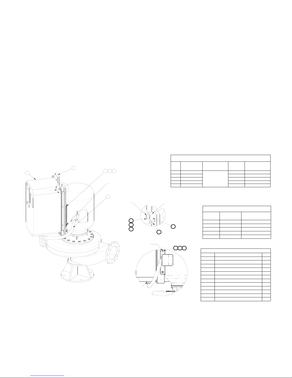
Figure 7-1: VFD Mounting to Pump
1.Items specified on this drawing are specifically for the SKV or SKS product series.
2.Assemble safety strap onto isolation mount stud to produce orientation shown in the assembly drawing.
3.Apply 'Loctite' to isolation mount stud threads (1 place) on all 4x parts.
4.Assemble threaded stud with 'Loctite' into bar bracket until surfaces are in contact without gaps.
5.Use strap wrench for isolation mounts. Screw mount into bar bracket (#2) until the rubber face is flush against the
bar. Torque the mount 1/4 of a full turn.
6.Support VFD & assemble onto 4 isolation mounts simultaneously, assemble lockwashers & nuts, torque to specifications "C", remove VFD support.
7.Assemble the motor so the feet are angled between 22.5° to 45° offset from the flanges, as shown below.
8.Assemble the motor so the VFD and motor conduit box are hanging over the outlet volute.
9.* = all "D" bolt connections are SAE J429 grade #2 steel - nickel plated.
TORQUE REQUIREMENTS
ALL TORQUE VALUES ARE +/- 15%
"A"
MOTOR POWER
SIZE
2
1
A
9310 11
"D"
DETAIL A
"C"
6
7
8
SCALE 1 : 4
"D"
"A"
APPLY LOCK TIGHT
BAR SIDE ONLY
5
ALTERNATIVE BRACKET VIEW
WIRES TO VFD
(In-lbs / Nm)
A5 5 / 0.6
B1 16 / 1.8 M8 X 1.25 11.3 / 15.3
B2 40 / 4.5 M8 X 1.25 11.3 / 15.3
C1 89 / 10 M8 X 1.25 11.3 / 15.3
C2 124 / 14 M8 X 1.25 11.3 / 15.3
"B"
4
9
10 11
"B"
VIBRATION MOUNT
TO BAR BRACKET
(In-lbs / Nm)
SEE NOTE #7
ALL TORQUE VALUES ARE +/- 15%
MOTOR
SIZE
143-145 5/16 X 18 11.5 / 15.6
182-215 3/8 X 16 20 / 27
254-286 1/2 X 13 49 / 66
324-365 5/8 X 11 98 / 133
404-449 3/4 X 10 173 / 235
SKV or SKS BOM Assembly
ITEM # DESCRIPTION QTY
1 VFD 1
2 BAR BRACKET 2
3 WIRE HARNESS - MOTOR POWER 1
4 VIBRATION ISOLATION MOUNT 4
5 SAFETY STRAP 4
6 NUT (VFD) 4
7 LOCK WASHER (VFD) 4
8 WASHER (VFD) 4
9 SCREW (MOTOR) 4
10 LOCK WASHER (MOTOR) 4
11 WASHER (MOTOR) 4
N/A "LOCTITE" (242; P/N 24231) N/A
VIBRATION
MOUNT
THREAD
SIZE
M6 X 1 4.3 / 5.8
TORQUE REQUIREMENTS
BOLT SIZE
"C"
VFD NUT TO
VIBRATION MOUNT
(Ft-lbs / Nm)
"D" MOTOR BOLT
TO BAR BRACKET
(FT-LBS / NM)*
302-365, Effective: June 5, 2017
© 2017 Taco, Inc.
5
Page 6
Taco® SKV
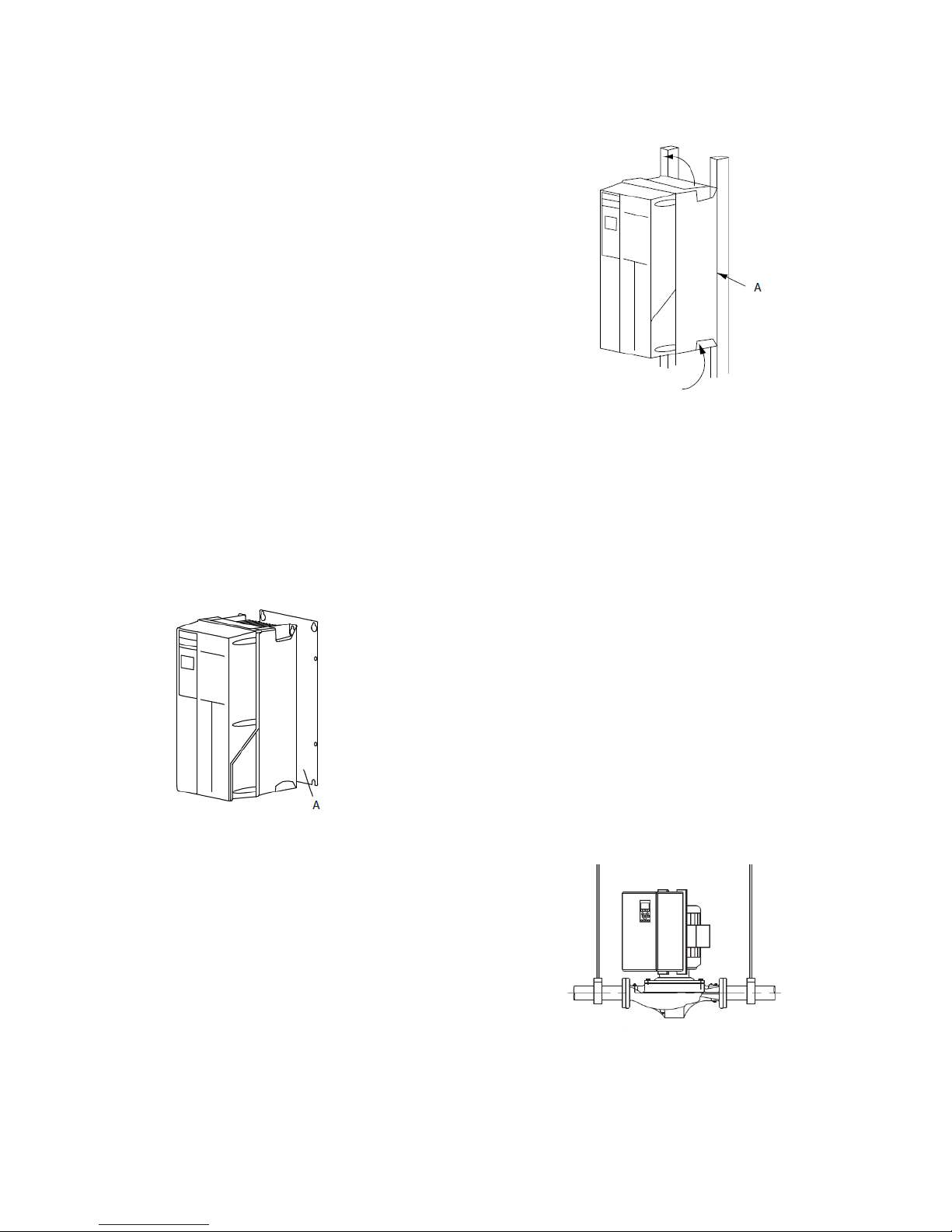
7.3 VFD Mounting to Wall
Figure 7-3: Proper Mounting with Railings
7.3.1 Lifting
• Check the weight of the unit to determine a safe lifting method.
• Ensure that the lifting device is suitable for the task.
• If necessary, plan for a hoist, crane, or forklift with the
appropriate rating to move the unit.
• For lifting, use hoist rings on the unit, when provided.
7.3.2 Mounting
• Mount the unit vertically.
• The frequency converter allows side by side installation.
• Ensure that the strength of the mounting location will
support the unit weight.
• Mount the unit to a solid flat surface or to the optional
back plate to provide cooling airflow (see Figure 7-2
and Figure 7-3).
• Improper mounting can result in overheating and
reduced performance.
• Use the slotted mounting holes on the unit for wall
mounting, when provided.
Figure 7-2: Proper Mounting with Back Plate
Item A is a back plate properly installed for required airflow to cool the unit.
7.3.3 Tightening Torques
See “17.2 Connection Tightening Torques” on page 77
for proper tightening specifications.
7.4 Pump Piping – Detailed
In order to achieve the full added value of the Vertical InLine pump design, it is important that you ensure the
pump is affixed to the system piping by the pump flanges
and the pump and motor assembly is allowed to float
freely with the expansion and contraction of the piping
system. Should any vertical in-line pump use supports to
the structure, it is imperative that no pipe strain is
imposed on the pump flanges. Compliant mounts such
as springs or “waffle”-style isolation pads should be used
under the pipe supports if the pump is not truly pipe
mounted.
Various installation arrangements are detailed in the figures that follow.
Figure 7-4: Hanger Supported, Pipe Mounted
NOTE: Back plate is required when mounted
on railings.
NOTE: The pump should not be rigidly attached to the base/pad structure unless flexible couplings are used.
6
302-365, Effective: June 5, 2017
© 2017 Taco, Inc.
Page 7

Taco® SKV
Vertical In-Line pumps may be installed directly in the
system piping with no additional support. Pipe hangers
are simply sized for the additional weight of the pumping
unit. Many pumps are installed in this manner and are
mounted at sufficient height to take zero floor space.
A similar arrangement to Figure 7-5 with additional floor
mounted pipe-stools isolated from the structure by 'waffle' style isolation pads under the Suction Diffuser (RSP)
and Plus Two Multi-Purpose Valve is illustrated in
(Figure 7-7).
(Figure 7-4)
Piping for smaller in-line pumps (typically 15 hp and
below) is hung close to the ceiling in many mechanical
rooms. Larger pumps are often mounted near ground
level for ease of maintenance. Figure 7-5 illustrates such
an arrangement with the piping supported at the ceiling
and the vertical pump installed with a Taco Suction Diffuser (RSP) and Plus Two Multi-Purpose Valve.
Figure 7-5: Pipe Mounted, Supported at Ceiling
Floor mounted saddle supports (Figure 7-8) are typical
for condenser water pumps where cooling tower base is
near mechanical room elevation.
Figure 7-7: With Additional Pipe Supports
Figure 7-8: Floor Saddle Support
Should additional space saving be required, the discharge spool piece and Plus Two Multi-Purpose Valve
may be replaced by a long-radius elbow and the Plus
Two Multi-Purpose Valve field converted to a straight pattern configuration and installed in the vertical discharge
pipe (Figure 7-6).
Figure 7-6: Discharge Elbow for Minimum
Footprint
Where required, additional floor support may be used as
shown in Figure 7-9. Install a “waffle” isolation pad under
the pump. NOTE: The pump should not be rigidly
attached to the base/pad structure.
Figure 7-9: Additional Floor Support
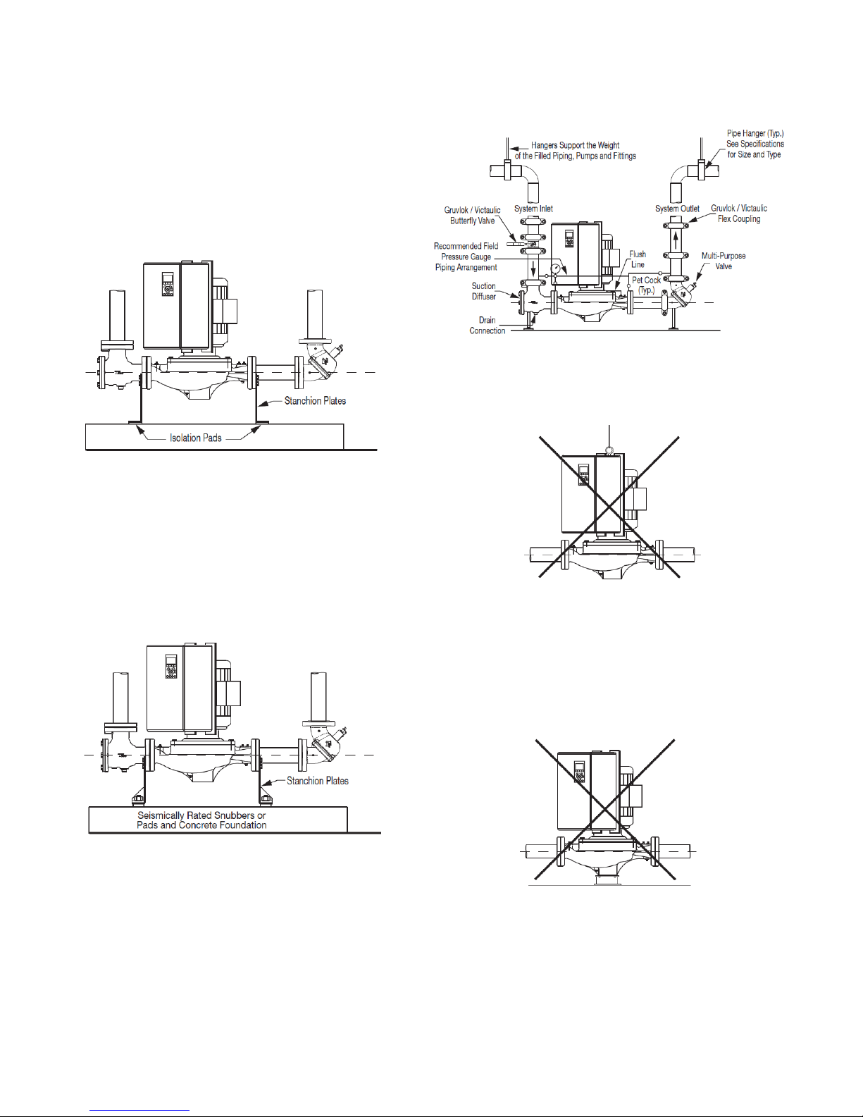
Stanchion plates at the pump suction and discharge ports
may be supplied for installation convenience. Isolation
© 2017 Taco, Inc.
7 302-365, Effective: June 5, 2017
Page 8
Taco® SKV
pads must be used under the legs and monitored as pipe
hangers are adjusted to ensure the pump flanges are not
supporting the piping. Bolting to the floor or housekeeping pad is not recommended. If the stanchions are bolted
down the bolts must be isolated from the stanchion or
inertia base and flexible pipe connectors used (Figure 7-
10).
Figure 7-10: With Stanchion Plates
An installation with stanchion plates for seismically active
regions is illustrated in Figure 7-11. Seismically rated isolation pads or snubbers with bolts isolated from the stanchion plates are installed to restrain the pump during a
seismic event. Pipe hangers carry the weight of the
equipment as seismic components are designed only to
restrain the equipment during a seismic event.
Figure 7-11: Installation in Seismically Active
Region
Figure 7-12: Mounting in Grooved Pipe Systems
DO NOT support the unit by the motor eye bolts
(Figure 7-13) or by any other part of the motor.
Figure 7-13: Motor Lifting Hook Supported
Connecting the pump to a permanent rigid base
(Figure 7-14) is not recommended unless isolated from
the piping by flexible connectors and the base isolated
from the building structure on an inertia base. (Figure 714 is generally acceptable when using plastic piping.)
Figure 7-14: Mounted on Rigid Base without
Flexible Connectors
In systems utilizing grooved pipe, flange adapter locking
devices or welded flanges at the pump should be used to
prevent the possibility of pipe mounted pumps rotating in
the piping (Figure 7-12).
NOTE: The pump should not be rigidly attached to the base/pad structure unless flexible couplings are used.
8
302-365, Effective: June 5, 2017
© 2017 Taco, Inc.
Page 9
8 ELECTRICAL CONNECTIONS
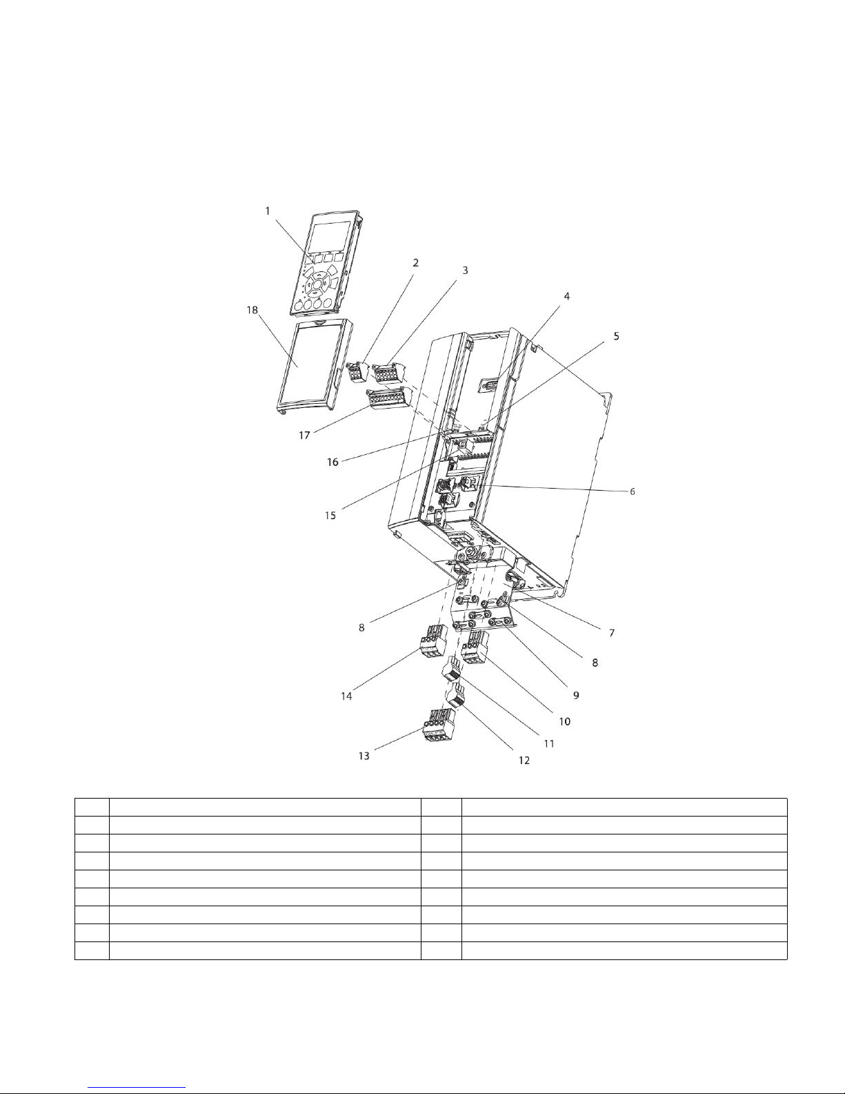
8.1 Exploded Views
Figure 8-1: Exploded View A Size
Taco® SKV
1 LCP 10 Motor output terminals 96 (U), 97 (V), 98 (W)
2 RS-485 serial bus connector (+68, -69) 11 Relay 1 (01, 02, 03)
3 Analog I/O connector 12 Relay 2 (04, 05, 06)
4 LCP input plug 13 Brake (-81, +82) and load sharing (-88, +89) terminals
5 Analog switches (A53), (A54) 14 Line power input terminals 91 (L1), 92 (L2), 93 (L3)
6 Cable strain relief / PE ground 15 USB connector
7 Decoupling plate 16 Serial bus terminal switch
8 Grounding clamp (PE) 17 Digital I/O and 24 V power supply
9 Shielded cable grounding clamp and strain relief 18 Control cable coverplate
302-365, Effective: June 5, 2017
© 2017 Taco, Inc.
9
Page 10
Taco® SKV
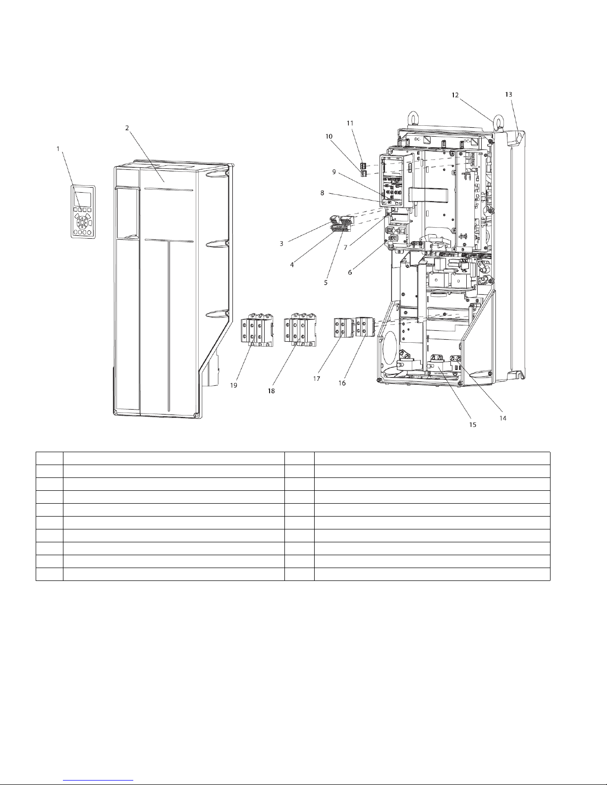
Figure 8-2: Exploded View B and C Sizes
1 LCP 11 Relay 2 (04, 05, 06)
2 Cover 12 Lifting ring
3 RS-485 serial bus connector 13 Mounting slot
4 Digital I/O and 24 V power supply 14 Grounding clamp (PE)
5 Analog I/O connector 15 Cable strain relief / PE ground
6 Cable strain relief / PE ground 16 Brake terminal (-81, +82)
7 USB connector 17 Load sharing terminal (DC bus) (-88, +89)
8 Serial bus terminal switch 18 Motor output terminals 96 (U), 97 (V), 98 (W)
9 Analog switches (A53), (A54) 19 Line power input terminals 91 (L1), 92 (L2), 93 (L3)
10 Relay 1 (01, 02, 03)
8.2 Electrical Installation
This section contains detailed instructions for wiring the adjustable frequency drive. The following tasks are described.
• Wiring the motor to the adjustable frequency drive output terminals
• Wiring the AC line power to the adjustable frequency drive input terminals
• Connecting control and serial communication wiring
• After power has been applied, checking input and motor power; programming control terminals for their intended
functions
10
302-365, Effective: June 5, 2017
© 2017 Taco, Inc.
Page 11
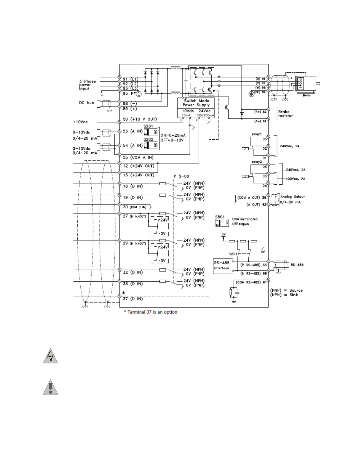
Figure 8-3 shows a basic electrical connection.
Figure 8-3: Basic Wiring Schematic Drawing
Taco® SKV
DANGER: EQUIPMENT HAZARD! Rotating shafts and electrical equipment can be hazardous. All electrical work must conform to national and local electrical codes. It is strongly recommended that installation,
start-up, and maintenance be performed only by trained and qualified personnel. Failure to follow these
guidelines could result in death or serious injury.
CAUTION: WIRING ISOLATION! Run input power, motor wiring and control wiring in three separate
metallic conduits or use separated shielded cable for high frequency noise isolation. Failure to isolate
power, motor and control wiring could result in less than optimum adjustable frequency drive and associated equipment performance.
302-365, Effective: June 5, 2017
© 2017 Taco, Inc.
11
Page 12
Taco® SKV
For your safety, comply with the following requirements:
• Electronic controls equipment is connected to hazardous AC line voltage. Extreme care should be
taken to protect against electrical hazards when
applying power to the unit.
• Run motor cables from multiple adjustable frequency
drives separately. Induced voltage from output motor
cables run together can charge equipment capacitors
even with the equipment turned off and locked out.
8.2.1 Overload and Equipment Protection
• An electronically activated function within the adjustable frequency drive provides overload protection for
the motor. The overload calculates the level of
increase to activate timing for the trip (controller output stop) function. The higher the current draw, the
quicker the trip response. The overload provides
Class 20 motor protection. See “14 Warnings and
Alarms” on page 61 for details on the trip function.
• Because the motor wiring carries high frequency current, it is important that wiring for line power, motor
power, and control is run separately. Use metallic
conduit or separated shielded wire. Failure to isolate
power, motor, and control wiring could result in less
than optimum equipment performance. See Figure 8-
4.
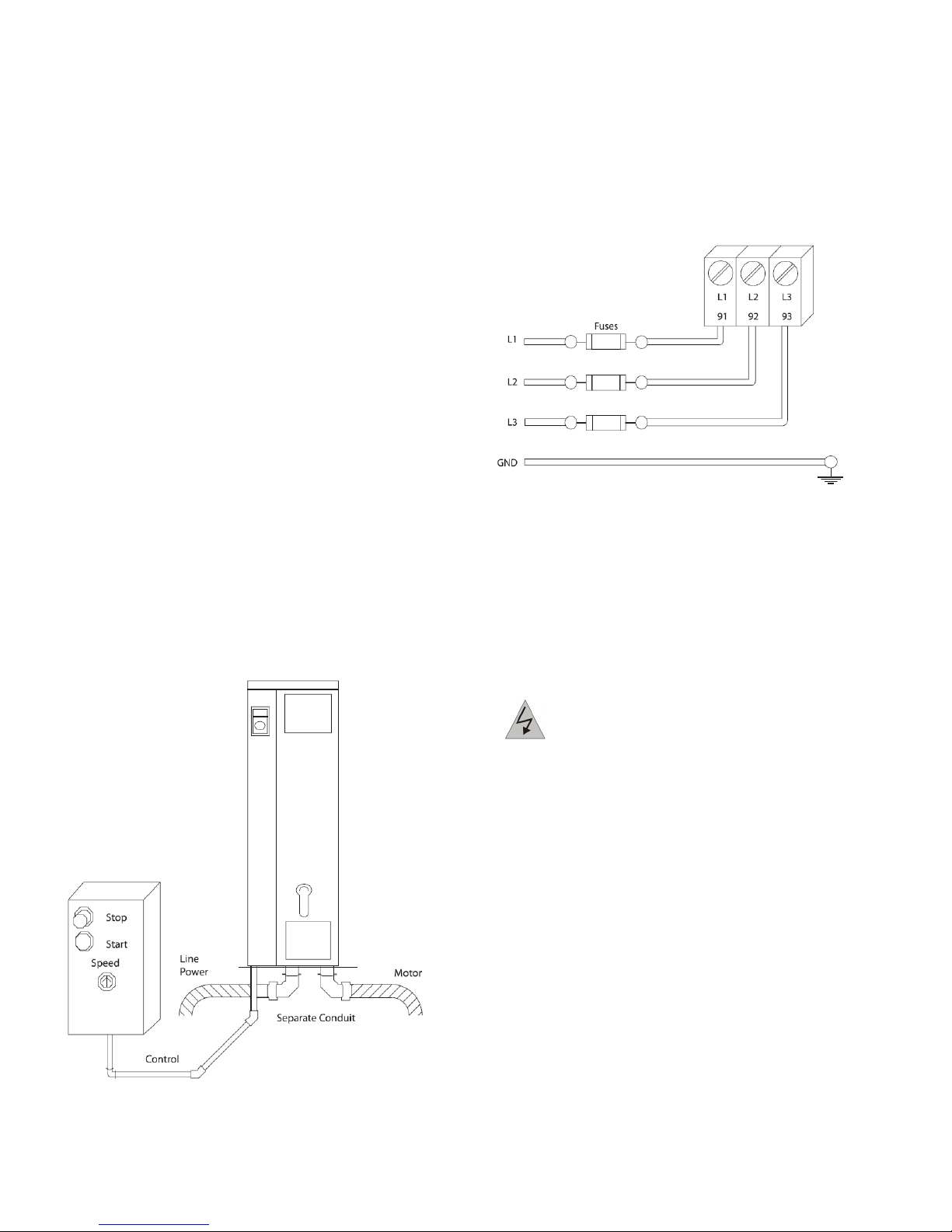
Figure 8-4: Proper Electrical Installation Using
Flexible Conduit
All adjustable frequency drives must be provided with
short-circuit and overcurrent protection. Input fusing is
required to provide this protection, see Figure 9.2.3. If not
factory supplied, fuses must be provided by the installer
as part of installation.
Figure 8-5: Adjustable Frequency Drive Fuses
Wire Type and Ratings
• All wiring must comply with local and national regulations regarding cross-section and ambient temperature requirements.
• Danfoss recommends that all power connections be
made with a minimum 167°F [75 °C] rated copper
wire.
8.3 Grounding Requirements
DANGER: GROUNDING HAZARD! For
operator safety, it is important to ground
adjustable frequency drive properly in accordance with national and local electrical
codes as well as instructions contained
within these instructions. Ground currents
are higher than 3.5 mA. Failure to ground the
adjustable frequency drive properly could
result in death or serious injury.
NOTE: It is the responsibility of the user or certified electrical installer to ensure correct grounding of the equipment in accordance with national and local electrical
codes and standards.
• Follow all local and national electrical codes to
ground electrical equipment properly.
• Proper protective grounding for equipment with
ground currents higher than 3.5 mA must be established, see Leakage Current (>3.5 mA).
• A dedicated ground wire is required for input power,
motor power and control wiring.
12
302-365, Effective: June 5, 2017
© 2017 Taco, Inc.
Page 13
Taco® SKV
• Use the clamps provided with on the equipment for
proper ground connections.
• Do not ground one adjustable frequency drive to
another in a “daisy chain” fashion.
• Keep the ground wire connections as short as possible.
• Use of high-strand wire to reduce electrical noise is
recommended.
• Follow the motor manufacturer wiring requirements.
8.3.1 Leakage Current (>3.5 mA)
Follow national and local codes regarding protective
grounding of equipment with a leakage current > 3.5 mA.
Adjustable frequency drive technology implies high frequency switching at high power. This will generate a leakage current in the ground connection. A fault current in
the adjustable frequency drive at the output power terminals might contain a DC component which can charge
the filter capacitors and cause a transient ground
current. The ground leakage current depends on
various system con"gurations including RFI filtering,
shielded motor cables, and adjustable frequency drive
power.
EN/IEC61800-5-1 (Power Drive System Product Standard)
requires special care if the leakage current exceeds
3.5mA.
Grounding must be reinforced in one of the following
ways:
• Ground wire of at least 0.0155 in2 [10mm2]
• Two separate ground wires both complying with the
dimensioning rules
See EN/IEC61800-5-1 and EN50178 for further information.
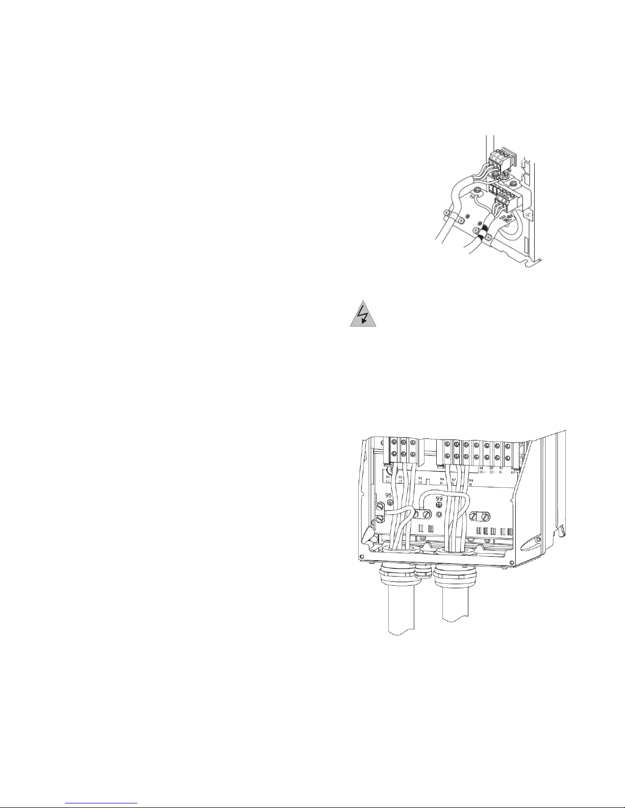
8.3.3 Grounding Using Shielded Cable
Grounding clamps are provided for motor wiring (see
Figure 8-6).
Figure 8-6:
Grounding with Shielded Cable
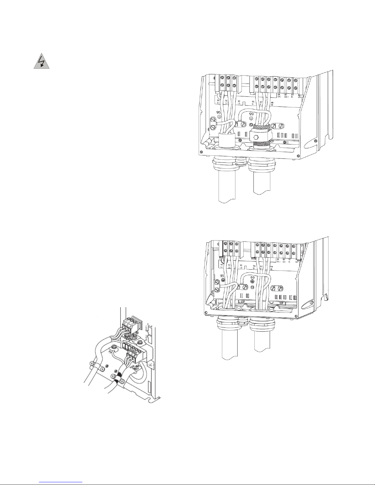
8.3.4 Grounding Using Conduit
DANGER: GROUNDING HAZARD! Do not
use conduit connected to the adjustable frequency drive as a replacement for proper
grounding. Ground currents are higher than
3.5 mA. Improper grounding can result in
personal injury or electrical shorts.
Dedicated grounding clamps are provided (See Figure 8-
7).
Figure 8-7: Grounding with Conduit
8.3.2 Using RCDs
Where residual current devices (RCDs), also known as
ground leakage circuit breakers (ELCBs), are used, comply with the following:
• Use RCDs of type B only which are capable of
detecting AC and DC currents
• Use RCDs with an inrush delay to prevent faults due
to transient ground currents
• Dimension RCDs according to the system configuration and environmental considerations
302-365, Effective: June 5, 2017
© 2017 Taco, Inc.
1.Use a wire stripper to remove the insulation for
proper grounding.
2.Secure the grounding clamp to the stripped portion
of the wire with the screws provided.
3.Secure the grounding wire to the grounding clamp
provided.
13
Page 14
Taco® SKV
8.3.5 Motor Connection
DANGER: INDUCED VOLTAGE! Run out-
put motor cables from multiple adjustable
frequency drives separately. Induced voltage
from output motor cables run together can
charge equipment capacitors even with the
equipment turned off and locked out. Failure
to run output motor cables separately could
result in death or serious injury.
• For maximum wire sizes, see “17.1 Power-dependent Specifications” on page 75.
• Comply with local and national electrical codes for
cable sizes.
• Motor wiring knockouts or access panels are provided at the base of IP21 and higher (NEMA1/12)
units
• Do not install power factor correction capacitors
between the adjustable frequency drive and the
motor
• Do not wire a starting or pole-changing device
between the adjustable frequency drive and the
motor.
• Connect the 3-phase motor wiring to terminals 96
(U), 97 (V), and 98 (W).
• Ground the cable in accordance with grounding
instructions provided.
• Follow the motor manufacturer wiring requirements
The three following figures represent line power input,
motor, and grounding for basic adjustable frequency
drives. Actual configurations vary with unit types and
optional equipment.
Figure 8-8: Motor, Line Power and Ground Wiring
for A-Frame Sizes
Figure 8-9: Motor, Line Power and Ground Wiring
for B-Frame Sizes and Above Using Shielded
Cable
Figure 8-10: Motor, Line Power and Ground
Wiring B-Frame Sizes and Above Using
Shielded Cable or Conduit
14
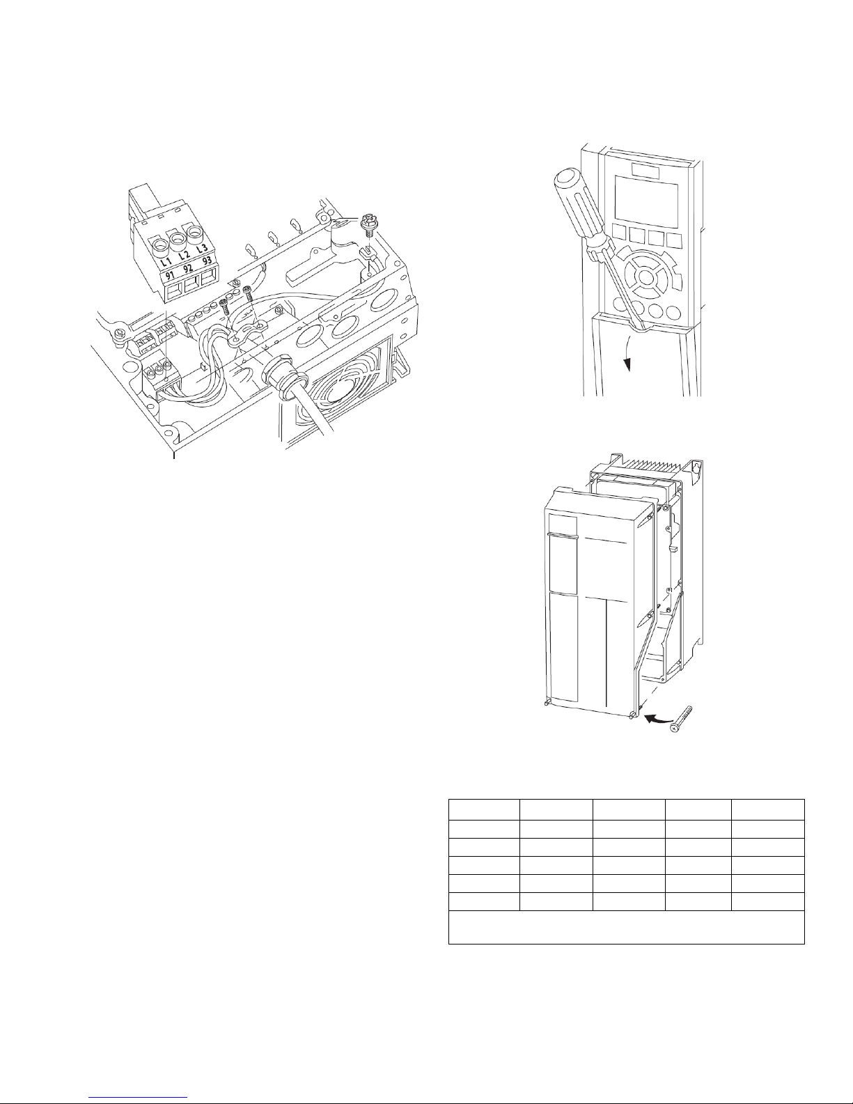
8.3.6 AC Line Power Connection
Size wiring based upon the input current of the adjustable
frequency drive.
• Comply with local and national electrical codes for
cable sizes.
• Connect 3-phase AC input power wiring to terminals
L1, L2, and L3 (see Figure 8-11).
302-365, Effective: June 5, 2017
© 2017 Taco, Inc.
Page 15
Taco® SKV
• Depending on the configuration of the equipment,
input power will be connected to the line power input
terminals or the input disconnect.
Figure 8-11: Connecting to AC Line Power
• Ground the cable in accordance with grounding
instructions provided in “8.3 Grounding Requirements” on page 12.
• All adjustable frequency drives may be used with an
isolated input source as well as with ground reference power lines. When supplied from an isolated
line power source (IT line power or floating delta) or
TT/TN-S line power with a grounded leg (grounded
delta), set 14-50 RFI 1 to OFF. When off, the internal
RFI filter capacitors between the chassis and the
intermediate circuit are isolated to avoid damage to
the intermediate circuit and to reduce ground capacity currents in accordance with IEC 61800-3.
Figure 8-12: Control Wiring Access for A2, A3,
B3, B4, C3 and C4 Enclosures
Figure 8-13: Control Wiring Access for A4, A5,
B1, B2, C1 and C2 Enclosures
8.3.7 Control Wiring
Isolate control wiring from high power components in the
adjustable frequency drive.
If the adjustable frequency drive is connected to a thermistor, for PELV isolation, optional thermistor control wiring
must be reinforced/ double insulated. A 24 VDC supply
voltage is recommended.
Access
Remove access coverplate with a screwdriver. See “Figure 8-12: Control Wiring Access for A2, A3, B3, B4, C3
and C4 Enclosures” on page 15.
Or remove front cover by loosening attaching screws.
See “Figure 8-13: Control Wiring Access for A4, A5, B1,
B2, C1 and C2 Enclosures” on page 15.
302-365, Effective: June 5, 2017
© 2017 Taco, Inc.
Please see the table below before tightening the covers.
Table 1: Tightening Torques for Covers (Nm)
Frame IP20 IP21 IP55 IP66
A4/A5 - - 2 2
B1 - * 2.2 2.2
B2 - * 2.2 2.2
C1 - * 2.2 2.2
C2 - * 2.2 2.2
* No screws to tighten
- Does not exist
15
Page 16
Taco® SKV
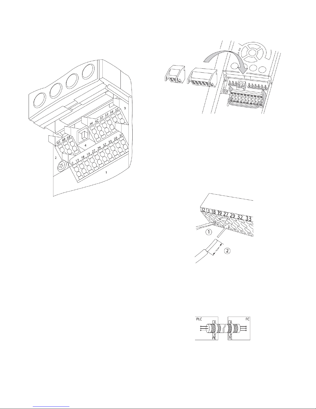
Control Terminal Types
Figure 8-14 shows the removable adjustable frequency
drive connectors.
Figure 8-14: Control Terminal Locations
Figure 8-15: Unplugging Control Terminals
1.Open the contact by inserting a small screwdriver
into the slot above or below the contact, as shown
in Figure 8-16.
2.Insert the bared control wire into the contact.
3.Remove the screwdriver to fasten the control wire
into the contact.
4.Ensure the contact is firmly established and not
loose. Loose control wiring can be the source of
equipment faults or less than optimal operation.
Figure 8-16: Connecting Control Wiring
• Connector 1 provides four programmable digital
inputs terminals, two additional digital terminals programmable as either input or output, a 24V DC terminal supply voltage, and a common for optional
customer supplied 24V DC voltage.
• Connector 2 terminals (+)68 and (-)69 are for an RS485 serial communications connection.
• Connector 3 provides two analog inputs, one analog
output, 10V DC supply voltage, and commons for the
inputs and output.
• Connector 4 is a USB port available for use with the
MCT-10 Set-up Software.
• Also provided are two Form C relay outputs that are
in various locations depending upon the adjustable
frequency drive configuration and size.
Wiring to Control Terminals
Control terminal connectors can be unplugged from the
adjustable frequency drive for ease of installation, as
shown in Figure 8-15.
Using Shielded Control Cables
Correct Shielding
The preferred method in most cases is to secure control
and serial communication cables with shielding clamps
provided at both ends to ensure best possible high frequency cable contact.
16
302-365, Effective: June 5, 2017
© 2017 Taco, Inc.
Page 17
Taco® SKV
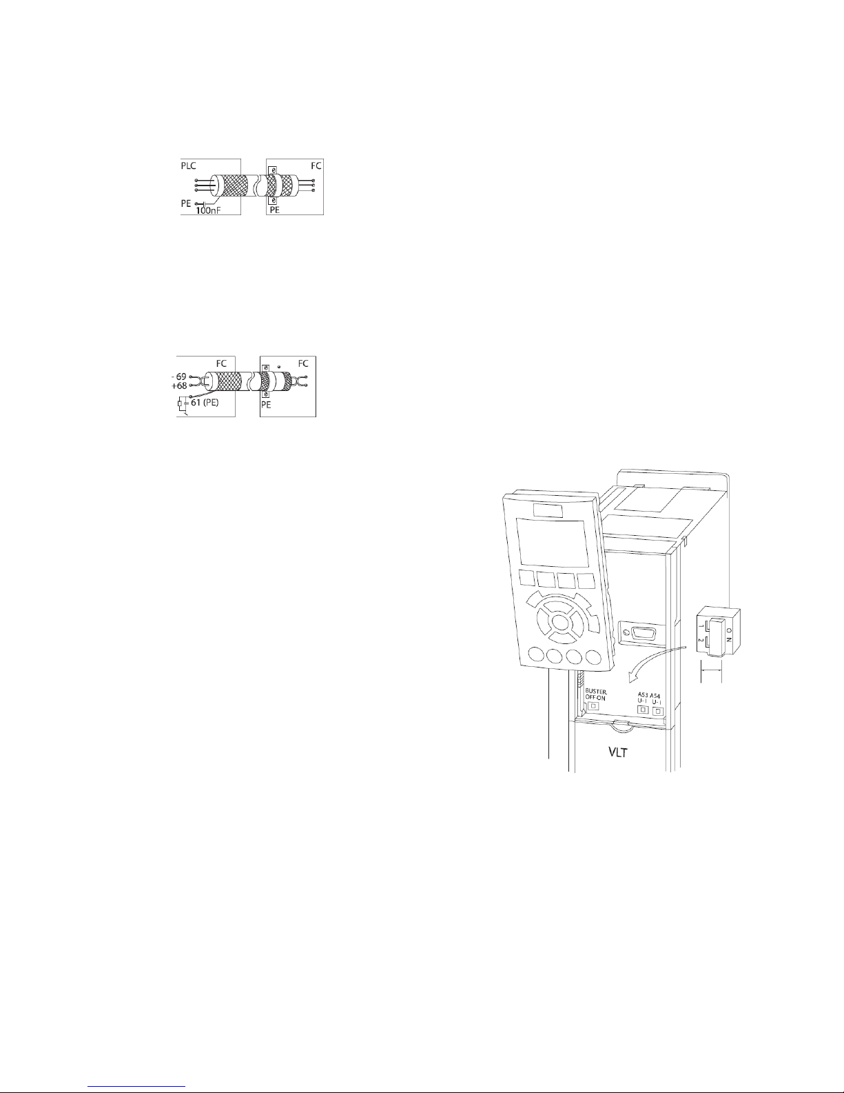
50/60 Hz ground loops
With very long control cables, ground loops may occur.
To eliminate ground loops, connect one end of the shieldtoground with a 100 nF capacitor (keeping leads short).
Avoid EMC noise on serial communication
To eliminate low-frequency noise between adjustable frequency drives, connect one end of the shield to terminal
61. This terminal is connected to ground via an internal
RC link. Use twisted-pair cables to reduce interference
between conductors.
Control Terminal Functions
Adjustable frequency drive functions are commanded by
receiving control input signals.
• Each terminal must be programmed for the function it
will be supporting in the parameters associated with
that terminal.
• It is important to confirm that the control terminal is
programmed for the correct function. See “9 User
Interface” on page 28for details on accessing parameters..
• The default terminal programming is intended to initiate adjustable frequency drive functioning in a typical
operational mode.
Jumper Terminals 12 and 27
A jumper wire may be required between terminal 12 (or
13) and terminal 27 for the adjustable frequency drive to
operate when using factory default programming values.
• Digital input terminal 27 is designed to receive an
24VDC external interlock command. In many applications, the user wires an external interlock device to
terminal 27.
• When no interlock device is used, wire a jumper
between control terminal 12 (recommended) or 13 to
terminal 27. This provides an internal 24 V signal on
terminal 27.
• No signal present prevents the unit from operating.
• When the status line at the bottom of the LCP reads
“AUTO REMOTE COASTING” or “Alarm 60 External
Interlock” is displayed, this indicates that the unit is
ready to operate but is missing an input signal on terminal 27.
• When factory installed optional equipment is wired to
terminal 27, do not remove that wiring.
Terminal 53 and 54 Switches
• Analog input terminals 53 and 54 can select either
voltage (0 to 10V) or current (0/4–20mA) input signals
• Remove power to the adjustable frequency drive
before changing switch positions.
• Set switches A53 and A54 to select the signal type. U
selects voltage, I selects current.
• The switches are accessible when the LCP has been
removed (see Figure 8-17). Note that some option
cards available for the unit may cover these switches
and must be removed to change switch settings.
Always remove power to the unit before removing
option cards.
• Terminal 53 default is for a speed reference signal in
open-loop set in 16-61 Terminal 53 Switch Setting
• Terminal 54 default is for a feedback signal in closedloop set in 16-63 Terminal 54 Switch Setting
Figure 8-17: Location of Terminals 53 and 54
Switches
302-365, Effective: June 5, 2017
© 2017 Taco, Inc.
17
Page 18

Taco® SKV
8.4 Typical Terminal Wiring Configurations
The unit connection blocks are shown in “Figure 8-14: Control Terminal Locations” on page 16.
Table 2: Control Terminal Information
Terminal
number
Relay Outputs 01, 02, 03 5-40 Relay 1 [160] No Alarm Form C Relay Output. Used for AC or DC voltages and either
04, 05, 06 5-40 Relay 2 [5] Running
Connector 1 12, 13 - +24 V DC 24 V DC supply voltage. Maximum output current is 200 mA
18 5-10 [8] Start Start/Stop digital input signal for the drive. Connect input to 24
19 5-11 [0] No Operation Digital input (not used)
27 5-12 [0] No Operation Digital input (not used)
29 5-13 [0] No Operation Digital input (not used)
32 5-14 [0] No Operation Digital input (not used)
33 5-15 [0] No Operation Digital input (not used)
20 - Common Common for digital inputs and reference for 24 V supply
Connector 2 61 - Shield Connection Integrated RC filter for cable shield. ONLY for connecting the
68 8-3 + RS485 Interface (+)
69 8-3 - RS485 Interface (-)
Connector 3 39 - AO Common Common for analog output
42 6-50 4-20mA Motor
50 - +10 V DC 10 V DC analog supply voltage. 15mA max.
53 6-1 [0] No Operation Analog input 53.
54 6-2 [0] No Operation Analog input 54.
55 - AI Common Common for analog input.
Parameter Default setting Description
resistive or inductive loads. see the following section on relay
wiring for contact current and voltage ratings.
total for all 24 V loads. Intended for digital inputs, external
transducers.
V to start. Open the input to stop the drive.
shield when experiencing EMC problems.
Analog output. Default setting is 4-20mA signal (500 ohms
Freq
maximum) based on motor speed.
18
302-365, Effective: June 5, 2017
© 2017 Taco, Inc.
Page 19
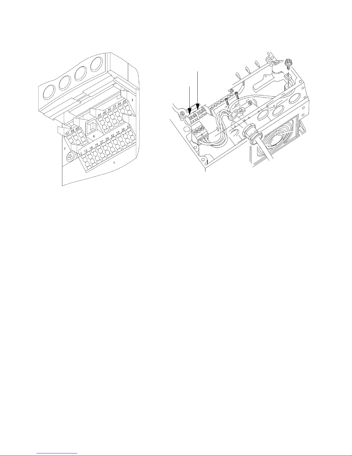
Figure 8-18: Control Terminal Connectors 1-4 and Relay Output Locations
Drive 1 Relay. Relay
1 is on the right in
this view.
Relay 2.
Taco® SKV
302-365, Effective: June 5, 2017
© 2017 Taco, Inc.
19
Page 20
Taco® SKV
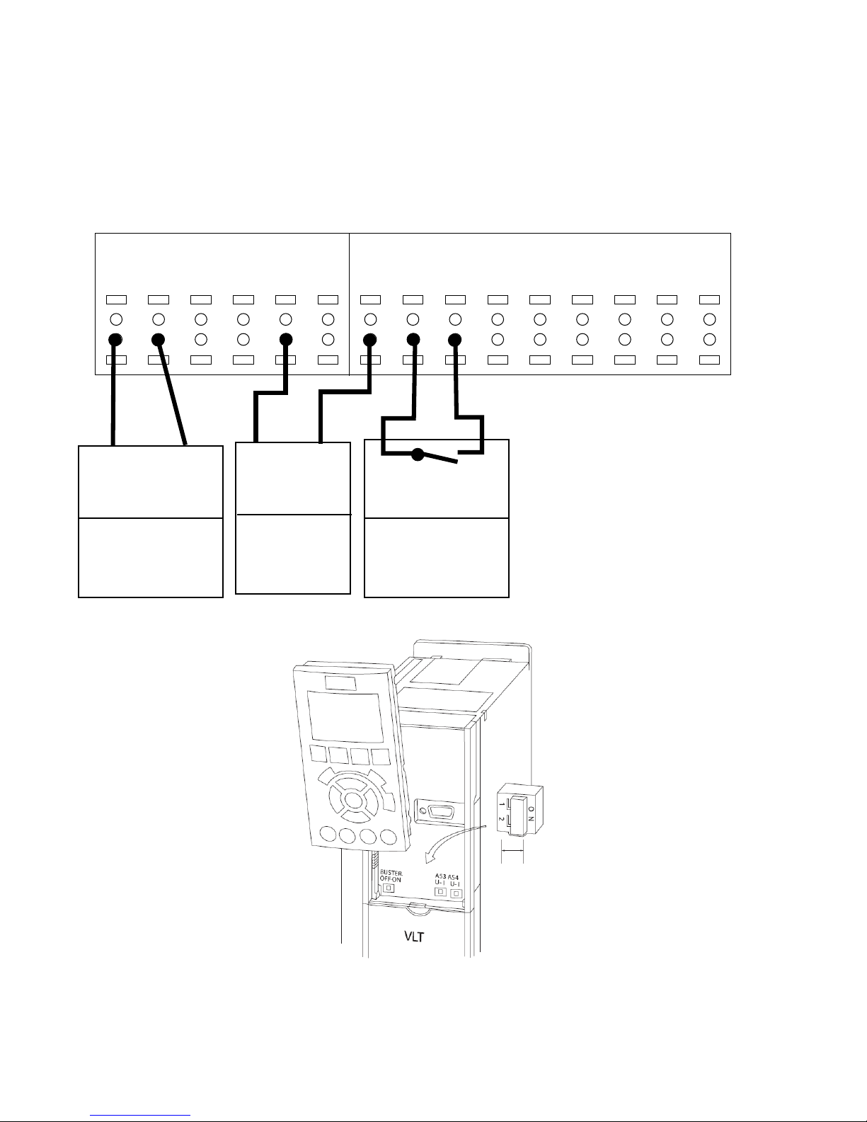
8.4.1 Factory default set-up
This configuration makes use of the controller factory default settings for input/output. The factory default settings are
configured for Set-up 1, SelfSensing system curve control without an external transducer. No parameters need to be
changed to use this configuration. Set-up 3, SelfSensing constant flow control, uses the same default settings.
Set-ups can be changed by modifying the parameter 0-10 Active Set-up.
NOTE: The factory default settings require a start signal wired to DI18 (see below).
Comm Port I/O Analog I/O Digital
61
SHLD
69
68
-39COM42AOUT50+10V53A IN
+
54
A IN
55
12
COM
+24V13+24V18D IN19D IN27D IN29D IN32D IN33D IN20COM
Starting/Stopping
Controller
[5-10]
[8] Start*
Start: Closed
* factory default
20
302-365, Effective:
© 2017 Taco, Inc.
June 5, 2017
Page 21
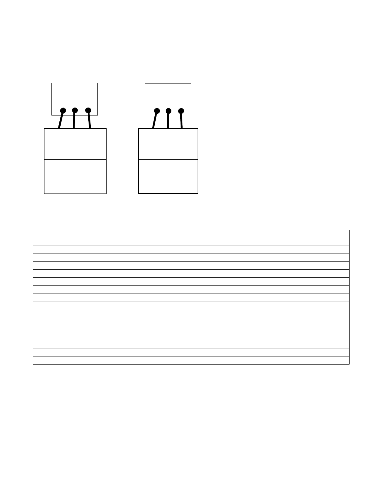
Taco® SKV
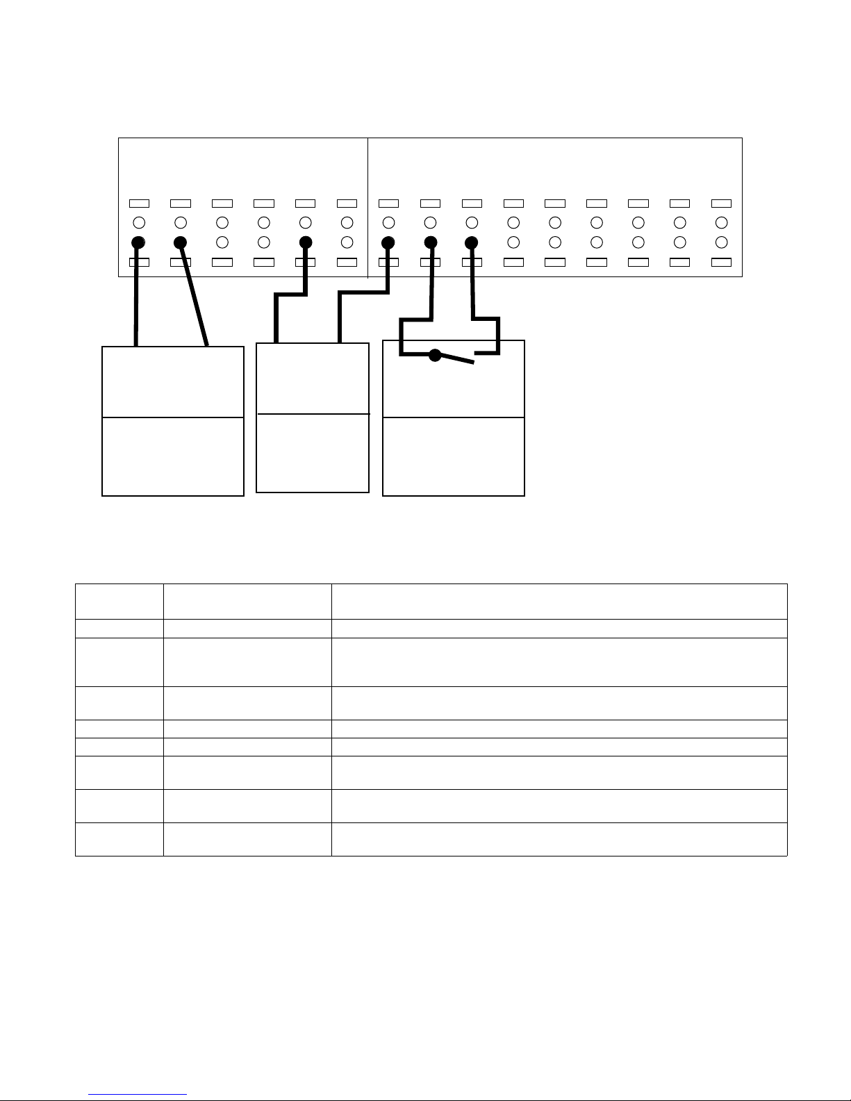
8.4.2 Relay Outputs
As shown above, each unit has two form C programmable relay outputs. The relay terminals can be found on the controller in various locations according to the frame size.
Figure 8-19: Wiring the Relay Terminals
Relay 1
01
02NO03
COM
COM
Unit Receiving
Output from
Relay 1
[5-40.0]
[160] No Alarm*
No Alarm: Comm=NO
Alarm: Comm = NC
NO
NC
NC
Relay 2
04
05NO06
COM
COM
Unit Receiving
Output from
Relay 2
[5-40.1]
[5] Running*
Running: Comm=NO
Off: Comm = NC
NO
NC
NC
* Factory Default Settings
Table 3: Relay Terminal Specifications
Programmable relay outputs 2
Relay 01 Terminal number 1–3 (break), 1–2 (make)
Maximum terminal load (AC-1) on 1–3 (NC), 1–2 (NO) (Resistive load) 240 V AC, 2A
Maximum terminal load (AC-15) (Inductive load @ cos 0.4) 240 V AC, 0.2A
Maximum terminal load (DC-1) on 1–2 (NO), 1–3 (NC) (Resistive load) 60 V DC, 1A
Maximum terminal load (DC-13) (Inductive load) 24 V DC, 0.1A
Relay 02 Terminal number 4–6 (break), 4–5 (make)
Maximum terminal load (AC-2) on 4–5 (NO) (resistive load) 400 V AC, 2A
Maximum terminal load (AC-15) (Inductive load @ cos 0.4) 240 V AC, 0.2A
Maximum terminal load (DC-1) on 4–5 (NO) (Resistive load) 80 V DC, 2A
Maximum terminal load (DC-13) on 4–5 (NO) (Inductive load) 24 V DC, 0.1A
Maximum terminal load (AC-1) on 4–6 (NC) (Resistive load) 240 V AC, 2A
Maximum terminal load (AC-15) on 4–6 (NC) (Inductive load @ cos 0.4) 240 V AC, 0.2A
Maximum terminal load (DC-1) on 4–6 (NC) (Resistive load) 50 V DC, 2A
Maximum terminal load (DC-13) on 4–6 (NC) (Inductive load) 24 V DC, 0.1A
Minimum terminal load on 1–3 (NC), 1–2 (NO), 4–6 (NC), 4–5 (NO) 24 V DC 10mA, 24 V AC 20mA
Environment according to EN 60664–1 overvoltage category III/pollution degree 2
302-365, Effective: June 5, 2017
© 2017 Taco, Inc.
21
Page 22
Taco® SKV
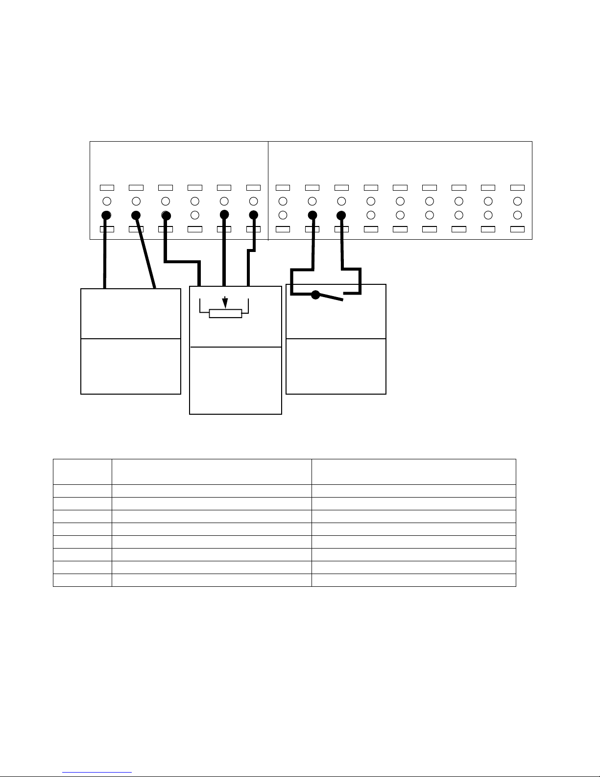
8.4.3 Adding Transducer Input
This configuration adds a transducer for closed loop control or external monitoring. Use Set-up 4 for pressure control
(Delta P) using a wired pressure transducer.
NOTE: Analog input configuration switches must be set before using the analog input, as shown in
Figure 8-21.
Figure 8-20: Terminal Wiring for 4–20mA Sensor Sensor
I/O Analog I/O Digital
39
COM42AOUT50+10V53A IN
COM
AI
Unit Receiving
Analog Output
A IN
AO
4-20 mA
Transducer
54
55
COM
+24V
12
+24V13+24V18D IN19D IN27D IN29D IN32D IN33D IN20COM
Starting/Stopping
Controller
(Optional)
[6-50]
[137] Speed*
4-20 mA
* factory default
[Group 6-]
[Group20-]
(See Table)
Set A54=I
[5-10]
[8] Start*
Start: Closed
* factory default
Figure 8-21: Location of Terminals 53 and 54 Switches
22
302-365, Effective: June 5, 2017
© 2017 Taco, Inc.
Page 23
The following wiring scheme is used with Set-up 4 as shown in “10.1 SelfSensing Description” on page 34.
Figure 8-22: Terminal Wiring for 0–10V Sensor
I/O Analog I/O Digital
Taco® SKV
39
COM42AOUT50+10V53A IN
COM
AI
Unit Receiving
Analog Output
54
A IN
AO
0-10V
Transducer
55
COM
+24V
12
+24V13+24V18D IN19D IN27D IN29D IN32D IN33D IN20COM
Starting/Stopping
Controller
(Optional)
[6-50]
[137] Speed*
4-20 mA
* factory default
[Group 6-]
[Group20-]
(See Table)
Set A54=U
[5-10]
[8] Start*
Start: Closed
* factory default
To configure the controller for closed loop control based on the input from an external transducer, use the following
parameters:
Table 4: Settings for a Wired Sensor for Input
Parameter
number
0–10 Active Set-up For wired pressure transducer, choose Set-up 4.
6-24* Terminal 54 Low Ref./Feedb.
Value
6-25* Terminal 54 High Ref./Feedb.
Value
6-27* Terminal 54 Live Zero Enabled
20-00 Feedback 1 Source Analog Input 54*
20-12 Reference/Feedback Set as appropriate for application. For example, set to PSI when using a pressure
20–13 Minimum Reference/Feed-
back
20–14 Maximum Reference/Feed-
back
Description Set to
Minimum transducer input value. For example, for a 0–100 PSI transducer, set to
0. For live 0 function set feedback to 1V or 10 PSI. Note: Live 0 does not work if
minimum is set to 0.
Maximum transducer input value. For example, for a 0–100 PSI transducer, set to
100.
transducer. The default value for this setting is PSI.
Minimum transducer input value. For example, for a 0–100 PSI transducer, set to
0 PSI.
Maximum transducer input value. For example, for a 100 PSI transducer, set to
100 PSI.
* To use AI 53, set parameters 6–14, 6–15, 6–17 and set 20–00 to “Analog Input 53.”
To set up the controller with a transducer that is intended for external monitoring, as opposed to feedback to the controller, set the following parameters:
302-365, Effective: June 5, 2017
© 2017 Taco, Inc.
23
Page 24

Taco® SKV
Table 5: Settings for a Wired Sensor for External Monitoring
Parameter
number
Description Set to
0-24 Display Line 3 Large Ext. 1 Feedback [Unit]
21-14 Ext. 1 Feedback Source Analog Input 54*
21–10 Ext. 1 Ref./Feedback Unit Select as appropriate for application. For example, set to PSI when using a
pressure transducer.
21–11 Ext. 1 Minimum Reference Minimum transducer input value. For example, for a 0–60 PSI transducer,
set to 0 PSI.
21–12 Ext. 1 Maximum Reference Maximum transducer input value. For example, for a 60 PSI transducer,
set to 60 PSI.
6–24* Terminal 54 Low Ref./Feedb. Value Minimum transducer input value. For example, for a 0–60 PSI transducer,
set to 0 PSI.
6–25* Terminal 54 High Ref./Feedb. Value Maximum transducer input value. For example, for a 60 PSI transducer,
set to 60 PSI.
6–27* Terminal 54 Live Zero Disabled
* To use AI 53, set parameters 6–14, 6–15, 6–17 and set 20-00 to “Analog Input 53.”
24
302-365, Effective:
© 2017 Taco, Inc.
June 5, 2017
Page 25
Taco® SKV
8.4.4 Speed control with external potentiometer
This configuration allows an external potentiometer to control the speed of the motor.To use this set-up, the analog
input must be configured as a voltage input.
The following wiring scheme is used with Set-up 2 as shown in “10.1 SelfSensing Description” on page 34.
Figure 8-23: Terminal Wiring for Potentiometer used as External Speed Reference
I/O Analog I/O Digital
39
COM42AOUT50+10V53A IN
COM
AI
Unit Receiving
Analog Output
(Optional)
[6-50]
[137] Speed*
4-20 mA
* factory default
A IN
+10V
Speed Control
Potentiometer
[1-00] [0] Open Loop
[3-15] [1] AI54
Group 6-
54
AI53
55
COM
12
+24V13+24V18D IN19D IN27D IN29D IN32D IN33D IN20COM
COM
Starting/Stopping
Controller
[5-10]
[8] Start*
Start: Closed
* factory default
Group 20(See Table)
Set A54=U
To set up the controller for speed control with an external potentiometer, set the following parameters:
Parameter
number
1-00 Configuration Mode Open Loop
3-15 Reference 1 Source Analog Input 54
6-20 Terminal 54 Low Voltage* 0 V
6-21 Terminal 54 High Voltage* 10 V
6-24 Terminal 54 Low Ref./Feedb. Value 0
6-25 Terminal 54 High Ref./Feedb. Value Maximum motor speed. For example, 2950 Hz.
6-27 Terminal 54 Live Zero Disabled.
20-00 Feedback 1 Source No Function
Description Set to
* Set switch A54 = U
302-365, Effective: June 5, 2017
© 2017 Taco, Inc.
25
Page 26
Taco® SKV
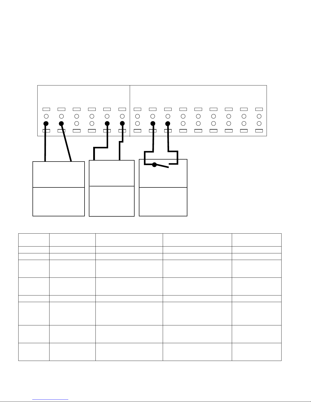
8.4.5 Control from external PLC/BMS through Analog Input
This set-up allows an external control source such as a PLC or BMS controller to provide: a) the process variable, b)
the setpoint or c) a speed reference. The output from the external control device can be either a voltage or current signal. The analog input configuration switches must be set to the correct type of output signal. The drawing below shows
the connections for this configuration.
This wiring scheme is used with Set-up 2, as shown in “10.1 SelfSensing Description” on page 34.
Figure 8-24: Terminal Wiring for External Control Source
I/O Analog I/O Digital
39
COM42AOUT50+10V53A IN
COM
AI
Unit Receiving
Analog Output
[6-50]
[137] Speed*
4-20 mA
* factory default
A IN
AO
PLC or BMS
Control Signal
[Group 6-]
[Group20-]
(See Table)
Set A54=U for 0-10V
Set A54=I for 4-20mA
54
55
12
COM
+24V13+24V18D IN19D IN27D IN29D IN32D IN33D IN20COM
COM
Starting/Stopping
Controller
[5-10]
[8] Start*
Start: Closed
* factory default
Table 6: Parameter Configuration for Use of an External Control Signal
Parameter
Number
1-00 Configuration Mode Closed Loop Closed Loop Open Loop
3-15 Reference 1 Source No Function Analog Input 54* Analog Input 54*
6-24 Terminal 54 Low Ref./
6-25 Terminal 54 High
6-27 Terminal 54 Live Zero Enabled Enabled Disabled
20-00 Feedback 1 Source Analog Input 54 Select as appropriate for applica-
20-12 Reference/Feedback
20-14 Maximum Reference/
Parameter
Description
Feedb. Value
Ref./Feedb. Value
Unit
Feedback
For process variable from
BMS/PLC*
Minimum value of process variable. For example, for a 0-60PSI
transducer, set to 0.
Maximum value of process variable. For example, for a 60PSI
transducer, set to 60.
Select as appropriate for application. For example, set to PSI
when using pressure feedback.
Maximum transducer feedback
value. For example, for a 60PSI
transducer, set to 60 PSI.
For setpoint from BMS/ PLC**
Minimum reference/setpoint
value. For example, for a 060PSI DP transducer, set to 0.
Maximum reference/setpoint
value. For example, for a 60PSI
DP transducer, set to 60.
tion. This can be any selection
except the setting of parameter
3-15.
Select as appropriate for application. For example, set to PSI
when using pressure reference.
Maximum reference/setpoint
value. For example, for a 60PSI
transducer, set to 60 PSI.
For speed reference
from BMS/PLC***
Minimum motor speed.
For example, 0 RPM.
Maximum motor speed.
For example, 2950
RPM.
No Function
NA
NA
26
302-365, Effective: June 5, 2017
© 2017 Taco, Inc.
Page 27

Taco® SKV
* To use AI 53, configure parameters 6-14, 6-15, 6-17 and set 20-00 to Analog Input 53
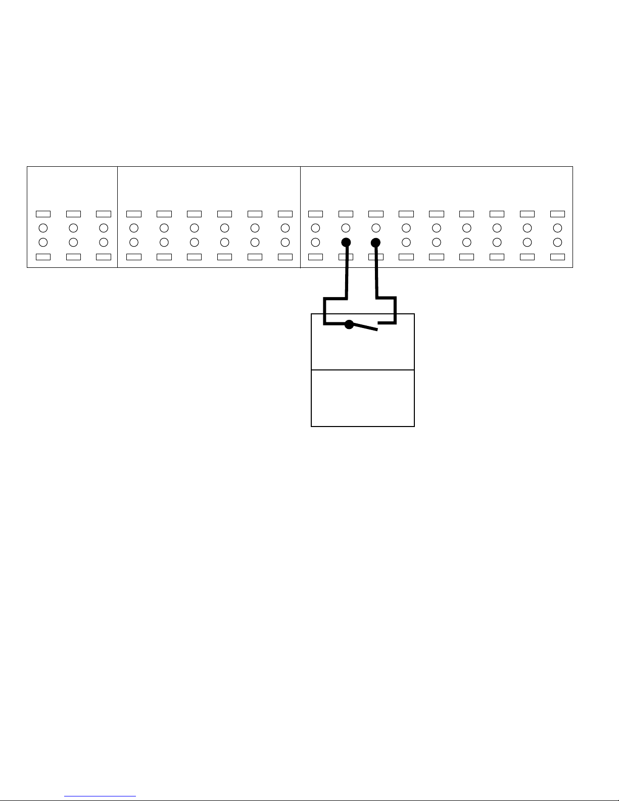
8.4.6 Control From External PLC/BMS Using Communications Port
The controller can be controlled from a BMS or PLC through the communications port. In this configuration, the BMS or
PLC overrides the setpoint to control the drive. Control cables must be braided screened/shielded and the screen must
be connected to the metal cabinet of the controller using two cable clamps (one at each end). The bus connections
must be terminated by turning the BUS TER switch to the on position. This switch can be found under the LCP, when
the LCP is detached.
This wiring scheme is used with Set-up 2, as shown in “10.1 SelfSensing Description” on page 34.
Figure 8-25: Terminal Connections for External Control via Communications Port
Comm Port
69
68
61
-
SHLD
+
SHLD
+
-
RS485
Controller
[8-**] Config params
Table 7: Parameter settings for Modbus RTU and BACnet protocols
Parameter Number Parameter Description Protocol
Modbus RTU BACnet
8-02 Control Source FC Port FC Port
8-30 Protocol Modbus RTU BACnet
8-31 Address 1 1
8-32 Baud Rate 19200 9600
8-33 Parity/Stop bit Even Parity, 1 Stop bit No Parity, 1 Stop bit
8-34 Estimated cycle time 0 ms 0 ms
8-35 Minimum Response Delay 10 ms 10 ms
8-36 Maximum Response Delay 5000 ms 5000 ms
8-37 Maximum Inter-Char Delay 0.86 ms 25 ms
The parameters above show a typical scenario used for Modbus RTU or BACnet protocols. The parameters must be
set as appropriate for the devices on the network. 8-32 Baud Rate and 8-33 Parity/Stop Bit should be set to match the
other devices on the network. For specific communication set-up information for Modbus RTU, refer to the document
number MG92B102. For specific communication set-up information for BACnet, see documents MG14C102 and
MG11D202. These documents can be downloaded from www.danfoss.com.
302-365, Effective: June 5, 2017
© 2017 Taco, Inc.
27
Page 28

Taco® SKV
9 USER INTERFACE
9.1 Local Control Panel
The local control panel (LCP) is the combined display
and keypad on the front of the unit. The LCP is the user
interface to the adjustable frequency drive.
The LCP has several user functions.
• Start, stop, and control speed when in local control
• Display operational data, status, warnings and cautions
• Programming adjustable frequency drive functions
• Manually reset the adjustable frequency drive after a
fault when auto-reset is inactive
LCP Layout
The LCP is divided into four functional groups (see
Figure 9-1).
Figure 9-1: LCP
b.Display menu keys for changing the display to
show status options, programming, or error message history.
c. Navigation keys for programming functions, mov-
ing the display cursor, and speed control in local
operation. Also included are the status indicators.
d.Operational mode keys and reset.
Setting LCP Display Values
The display area is activated when the adjustable frequency drive receives power from AC line voltage, a DC
bus terminal, or an external 24V supply.
The information displayed on the LCP can be customized
for user application.
• Each display readout has a parameter associated
with it.
• Options are selected in the quick menu Q3-13 Dis-
play Settings
• Display 2 has an alternate larger display option.
• The adjustable frequency drive status at the bottom
line of the display is generated automatically and is
not selectable.
.
A
B
C
D
Display
1.1 0-20 Head
1.2 0-21 Motor Horsepower
1.3 0-22 Motor Hz
2 0-23 GPM
Figure 9-2: Status Display
1.1
1.2
2
Display Menu Keys
Menu keys are used for menu access for parameter setup, toggling through status display modes during normal
operation, and viewing fault log data.
Parameter
number
Default setting
1.3
a.Display area
28
302-365, Effective:
© 2017 Taco, Inc.
June 5, 2017
Page 29

Key Function
Status Press to show operational information.
• In Auto mode, press and hold to toggle between
status readout displays.
• Press repeatedly to scroll through each status
display.
• Press and hold [Status] plus [ ] or [ ] to adjust
the display brightness.
• The symbol in the upper right corner of the display shows the direction of motor rotation and
which set-up is active. This is not programmable.
Quick
Menu
Main Menu Allows access to all programming parameters.
Alarm Log Displays a list of current warnings, the last 10
Allows access to programming parameters for initial set-up instructions and many detailed application instructions.
• Press to access Q2 Quick Set-up for sequenced
instructions to program the basic adjustable frequency drive set-up.
• Press to access Q3 Function Set-ups for
sequenced instructions to program applications
• Follow the sequence of parameters as presented for the function set-up.
• Press twice to access top level index.
• Press once to return to the last location
accessed.
• Press and hold to enter a parameter number for
direct access to that parameter.
alarms, and the maintenance log.
• For details about the adjustable frequency drive
before it entered the alarm mode, select the alarm
number using the navigation keys and press [OK].
Navigation Keys
Navigation keys are used for programming functions and
moving the display cursor. The navigation keys also provide speed control in local (hand) operation. Three
adjustable frequency drive status indicators are also
located in this area.
Taco® SKV
Figure 9-3: Navigation Keys
Key Function
Back Reverts to the previous step or list in the menu
structure.
Cancel Cancels the last change or command as long as
the display mode has not changed.
Info Press for a de!nition of the function being dis-
played.
Navigation
Keys
OK Use to access parameter groups or to enable a
Light Indicator Function
Green ON The ON light activates when the
Yellow WARN When warning conditions are met, the
Red ALARM A fault condition causes the red alarm
Use the four navigation arrows to move
between items in the menu.
choice.
adjustable frequency drive receives
power from AC line voltage, a DC bus
terminal, or an external 24 V supply.
yellow WARN light comes on and text
appears in the display area identifying
the problem.
light to flash and an alarm text is displayed.
302-365, Effective: June 5, 2017
© 2017 Taco, Inc.
29
Page 30

Taco® SKV
Operation Keys
Operation keys are found at the bottom of the control
panel.
Figure 9-4: Operation Keys
Key Function
Hand On Press to start the adjustable frequency drive in
local control.
• Use the navigation keys to control adjustable
frequency drive speed.
• An external stop signal by control input or
serial communication overrides the local hand
on.
Off Stops the motor but does not remove power to
the adjustable frequency drive.
Auto On Puts the system in remote operational mode.
• Responds to an external start command
bycontrol terminals or serial communication
• Speed reference is from an external source
Reset Resets the adjustable frequency drive manually
after a fault has been cleared.
9.2 Backup and Copying Parameter
Settings
Programming data is stored internally in the adjustable
frequency drive.
• The data can be uploaded into the LCP memory as a
storage backup.
• Once stored in the LCP, the data can be downloaded
back into the adjustable frequency drive.
• Initialization of the adjustable frequency drive to
restore factory default settings does not change data
stored in the LCP memory.
DANGER: UNINTENDED START! When
adjustable frequency drive is connected to
AC line power, the motor may start at any
time. The adjustable frequency drive, motor,
and any driven equipment must be in operational readiness. Failure to be in operational
readiness when the adjustable frequency
drive is connected to AC line power could
result in death, serious injury, equipment, or
property damage.
7.Apply power to the unit. Default parameter settings
are restored during start-up. This may take slightly
Uploading Data to the LCP
1.Press [OFF] to stop the motor before uploading or
downloading data.
2.Go to 0-50 LCP Copy.
3.Press [OK].
4.Select All to LCP.
5.Press [OK]. A progress bar shows the uploading
process.
6.Press [Hand On] or [Auto On] to return to normal
operation.
Downloading Data from the LCP
1.Press [OFF] to stop the motor before uploading or
downloading data.
2.Go to 0-50 LCP Copy.
3.Press [OK].
4.Select All from LCP.
5.Press [OK]. A progress bar shows the downloading
process.
6.Press [Hand On] or [Auto On] to return to normal
operation.
Restoring Default Settings
CAUTION: Initialization restores the unit to
factory default settings. Any programming,
motor data, localization, and monitoring
records will be lost. Uploading data to the
LCP provides a backup prior to initialization.
Restoring the adjustable frequency drive parameter settings back to default values is done by initialization of the
adjustable frequency drive. Initialization can be through
14-22 Operation Mode or manually.
• Initialization using 14-22 Operation Mode does not
change adjustable frequency drive data such as
operating hours, serial communication selections,
personal menu settings, fault log, alarm log, and
other monitoring functions.
• Using 14-22 Operation Mode is generally recommended.
• Manual initialization erases all motor, programming,
localization, and monitoring data and restores factory
default settings.
Recommended Initialization
1.Press [Main Menu] twice to access parameters.
2.Scroll to 14-22 Operation Mode.
3.Press [OK].
4.Scroll to Initialization.
5.Press [OK].
6.Remove power to the unit and wait for the display
to turn off.
longer than normal.
8.Press [Reset] to return to operation mode.
30
302-365, Effective: June 5, 2017
© 2017 Taco, Inc.
Page 31

Taco® SKV
Manual Initialization
1.Remove power to the unit and wait for the display
to turn off.
2.Press and hold [Status], [Main Menu], and [OK] at
the same time and apply power to the unit.
Factory default parameter settings are restored during
start-up. This may take slightly longer than normal.
Manual initialization does not reset the following adjustable frequency drive information:
• 15-00 Operating Hours
• 15-03 Power-ups
• 15-04 Over Temps
• 15-05 Over Volts
9.3 Password Protection
9.3.1 Enable Password Protection for
Main Menu
1.Press [Main Menu].
5.Scroll down to parameter 0-61 Access to
Main Menu w/o Password.
6.Press [OK].
7.Change parameter 0-61 to “[2] LCP: No Access.”
8.Press [OK].
2.Select 0-** Operation / Display by pressing [OK].
3.Scroll Down to parameter 0-6* Password.
4.Press [OK].
The Main Menu is now password protected. The default
password is 100.
9.3.2 Disable Main Menu Password
1.Follow steps 1-6 in section 9.3.1 above.
2.Change parameter 0-61 to “[0] Full Access.”
3.Press [OK].
The Main Menu Password is now disabled.
302-365, Effective: June 5, 2017
© 2017 Taco, Inc.
31
Page 32

Taco® SKV
9.3.3 Change Password for Main Menu
1.Follow steps 1-4 in section 9.3.1 above.
2.Scroll down to parameter 0-60 Main Menu
Password.
3.Press [OK].
4.Adjust/Edit the password using the arrow keys.
3.Scroll Down to parameter 0-6* Password.
4.Press [OK].
5.Scroll down to parameter 0-66 Access to
Personal Menu w/o Password.
6.Press [OK].
5.Press [OK].
The Main Menu password is now changed.
9.3.4 Enable Password Protection for My
Personal Menu
1.Press [Main Menu].
2.Select 0-** Operation / Display by pressing [OK].
7.Change parameter 0-66 to “[1] LCP: Read Only.”
8.Press [OK].
The My Personal Menu is now password protected. The
default password is 200.
9.3.5 Disable Password Protection for My
Personal Menu
1.Follow steps 1-3 in in section 9.3.4 above.
2.Change parameter 0-66 to “[0] Full Access.”
3.Press [OK].
32 302-365, Effective: June 5, 2017
The Personal Menu password protection is now disabled.
© 2017 Taco, Inc.
Page 33

9.3.6 Change Password for Personal
Menu
1.Follow steps 1-4 in in section 9.3.4 above.
2.Scroll down to parameter 0-65 Personal
Menu Password.
3.Press [OK].
4.Adjust/Edit the password using the arrow keys.
Taco® SKV
5.Press [OK].
The Personal Menu Pasword is now changed.
302-365, Effective: June 5, 2017
© 2017 Taco, Inc.
33
Page 34

Taco® SKV
10 PUMP CONTROL SET-UPS
10.1 SelfSensing Description
The Taco SelfSensing pump is a Taco pump equipped
with a variable frequency drive (VFD) with SelfSensing
control technology. SelfSensing control is an innovative
concept in circulating pumps. Pump performance and
characteristic curves are embedded in the memory of the
speed controller during manufacture. This data includes
power, speed, head and flow across the flow range of the
pump. During operation, the power and speed of the
pump are monitored, enabling the controller to establish
the hydraulic performance and position in the pumps
head-flow characteristic.
These measurements enable the pump to continuously
identify the head and flow at any point in time, giving
accurate pressure control without the need for external
feedback signals. Patented software technology within
the controller ensures trouble-free operation in all conditions.
Incorporating the pump’s hydraulic data into the controller and removing sensors results in true integration of all
components and removes the risk of sensor failure.
2.View the display to confirm the current set-up.
3.Press the [Quick Menus] button.
4.Press the [OK] button to enter “My Personal
Menu.”
5.Scroll down to Parameter 0-10 Active Set-up
and press OK.
10.2 Set-up Menu
The controller has 4 different system set-ups:
Set-up Description Instructions
Set-up 1 SelfSensing Variable Flow
Control
Set-up 2 Standby / BAS System Input Section 8.4.5
Set-up 3 SelfSensing Constant Flow
Control
Set-up 4 Delta P Control, 0-10V Input
(Wire Pressure Transducer)
10.2.1 Set-up Change Procedure
To change the set-up, follow the steps below.
1.If the pump is enabled, press the [Off] button and
ensure the motor has stopped.
Section 10.3 (Wiring:
Section 8.4.2)
Section 10.4 (Wiring:
Section 8.4.2)
Section 8.4.3
6.Change Active Set-up from “Set-up 1” to “Set-up 3”
and press OK.
a.Parameter 0-10 Active Set-up.
Before
After
b.You will know the change has happened when
you see change to .
34 302-365, Effective: June 5, 2017
© 2017 Taco, Inc.
Page 35

Taco® SKV
10.3 Variable Flow Control (Flow
Compensation)
Under Variable Flow Control (otherwise known as Flow
Compensation mode), the controller is set to control the
pump speed according to a ‘control curve’ between max
and min flow (see Figure 10-1 below). This mode should
be used for system distribution pumps. It is widely recognised that fitting a differential pressure sensor at the most
remote load, across the supply piping and return piping
encompassing the valve & coil set, is the benchmark
scheme for energy efficiency.
Figure 10-1: Variable Flow Graph
Control
Head
The pump will be supplied with point ‘A’ set as the design
duty point provided at the time of order and the minimum
head at zero flow (Control Head) will be set as 40% of the
design head ‘H
To change the control curve from the factory settings, follow the startup procedures in “Appendix B: On-site Drive
Mounting to Wall or Pump” on page 83.
’ as the default.
DESIGN
10.4 Constant Flow Control
SelfSensing pumps can be configured to maintain a constant pump flow in a system. This control setting is ideal
for primary systems such as boiler or chiller loops that
require a constant flow.
10.4.1 For Central Plant, Constant Flow
Boiler/Chiller
If this pump was ordered for a central plant constant flow
boiler/chiller, you do not need to go through the balancing
procedures below. Ensure the drive is already in Set-up 3
(SelfSensing Constant Flow Mode) and is therefore
already self-balancing.
Figure 10-2: Constant Flow Graph
SelfSensing pumps can replicate this control without the
need for the remote sensor. As the flow required by the
system is reduced, the pump automatically reduces the
head developed according to the pre-set control curve. In
other words, the pump follows the control curve.
It is often found that using a remote differential pressure
sensor to sense the pressure across a remote load could
theoretically result in loads close to the pump being
under-pumped. The situation would be where the load at
a loop extremity is satisfied and the control valve closes
while a load close to the pump needs full flow. The probability of this occuring is remote but it is possible. One
answer to this is to move the sensor closer to the pump
(two-thirds out in the system is a popular recommendation) although physically re-positioning the sensor at a
commissioning stage can be a costly exercise. With SelfSensing pump control it is possible to replicate the moving of a sensor by increasing the Control Head setting.
The design duty head and flow of the pump (provided at
time of order) is shown as point ‘A’ in Figure 10-1 below.
It is not always the case that the design duty point
required will fall on the maximum speed of the pump and
in the majority of cases (as shown in Figure 10-1 above)
it will be at a reduced speed.
To set the pump to constant flow mode and adjust the
flow rate, follow steps 1-12 in section 12.3.1.
10.4.2 Settings for Constant Flow Control
302-365, Effective: June 5, 2017
© 2017 Taco, Inc.
35
Page 36

Taco® SKV
10.5 Constant Pressure Control
SelfSensing pumps can be configured to maintain a constant pump head in a system as the demand varies. This
effectively simulates the mounting of a differential pressure sensor at, or near, the pump.
Figure 10-3: Constant Pressure Graph
10.5.1 Settings for Constant Pressure
Control
To revert to this mode of control simply follow these
steps:
1. Set the design head, H
point 1) in the units set in par. 20-12 (Reference/Feedback Unit).
2. Turn off flow compensation by setting par. 22-80 to
‘Disabled’ [0].
, value in par. 20-21 (Set-
DESIGN
For external sequencer wiring instructions, see “8.4.5
Control from external PLC/BMS through Analog Input” on
page 26.
10.6 Sequencing (Standby Pump
Alternation)
10.6.1 Onboard Pump Sequencer
The SelfSensing pump is equipped with a built-in pump
sequencer. The sequencer alternates 2 pumps back and
forth according to a time interval. The factory default is 24
hours. The maximum value is 99 hours. If the duty pump
has a fault or failure, the duty pump stops and the waiting
pump automatically starts.
For detailed connections and settings for the pump’s
onboard pump sequencer see “Appendix A: Set-Up for
Standby Pump Alternation” on page 78.
10.6.2 External Pump Sequencers
The SelfSensing pump can be sequenced with external
pump sequencers.
36 302-365, Effective: June 5, 2017
© 2017 Taco, Inc.
Page 37

Taco® SKV
11 START-UP PROCEDURE
11.1 Check Points Before First Start
Verify that motor is correctly wired for voltage available.
Verify that the pump has been primed. The pump should
never be run dry.
NOTE: Extra effort may be required to get
the air out of the seal chamber.
WARNING: Make sure power supply to
pump motor is locked out before touching
motor shaft.
Verify that all rotating parts turn freely.
11.2 Check Motor Rotation
Before running the frequency converter, check the motor
rotation. The motor will run briefly at 20Hz or the minimum frequency set in 4-12 Motor Speed Low Limit [Hz].
1.Check Motor rotation.
a.Press [Quick Menu].
b.Scroll to Q2 Quick Set-up.
c. Press [OK].
d.Scroll to 1-28 Motor Rotation Check.
e.Press [OK].
f. Scroll to Enable.
g.The following text appears: “Note! Motor may run
in wrong direction.”
h.Press [OK].
i. Follow the on-screen instructions.
NOTE: To change the direction of rotation,
remove power to the frequency converter
and wait for power to discharge. Reverse the
connection of any two of the three motor
cables on the motor or frequency converter
side of the connection.
The pump should be stopped if any of the following
occur:
• No discharge.
• Insufficient discharge.
• Insufficient pressure.
• Loss of suction.
• Excessive power consumption.
• Vibration.
See “16 SKS Pump Problem Analysis” on page 74 for
help in troubleshooting.
2.To navigate on the keypad, use the [OK] and
[ARROW] buttons shown below.
3.Ensure the drive is in Set-up 1.
11.3 Start Pump
CAUTION: MOTOR START! Ensure that the
motor, system, and any attached equipment
is ready for start. It is the responsibility of the
user to ensure safe operation under any condition. Failure to ensure that the motor, system, and any attached equipment is ready
for start could result in personal injury or
equipment damage.
5.Press the [OK] button to enter “My Personal
302-365, Effective: June 5, 2017
© 2017 Taco, Inc.
4.To change to Set-up 1, press the [Quick Menus]
button.
37
Page 38

Taco® SKV
Menu.”
6.Scroll down to Parameter 0-10 Active Set-up
and press OK.
7.Change Active Set-up to “Set-up 1”.
a.Parameter 0-10 Active Set-up.
Before
After
11.4 Verify Flow
The VFD is factory programmed with the Design Pressure Head and Design VFD Speed that were indicated at
the time of order.
If this pump was ordered for a system distribution pump
(quadratic system curve), it ships in Set-up 1 (it will track
a system control curve like the one shown in Figure 10-
1).
Follow the steps below to determine whether the pump is
producing the required amount of flow.
13.Close zone valves to ensure pump speed slows
as demand is reduced. Then open the valves to
ensure the pump increases speed until it reaches
the desired flow.
14.If the pump is not meeting the desired flow conditions, as shown in the figure below, see “12 System
Balancing” on page 39.
Figure 11-1: Over-sized Pump Example
b.You will know the change has happened when
you see change to .
8.Press the [Status] button to get back to the main
screen.
9.Close the discharge valve before starting pump.
DANGER: MAKE SURE SUCTION VALVE
IS OPEN!!
10.Press the [Auto on] button.
11.Once the pump has started, open the discharge
valve slowly.
CAUTION: Do not operate pump for prolonged periods with discharge valve closed,
to avoid overheating and potentially damaging loads.
12.After the discharge valve is fully open, let the
drive ramp up to the design flow point that was
specified.
IMPORTANT: Allow the pump enough time
to settle out at the specified design flow.
38 302-365, Effective: June 5, 2017
© 2017 Taco, Inc.
Page 39

Taco® SKV
12 SYSTEM BALANCING
12.1 About SelfSensing ProBalance
The pump is equipped with SelfSensing ProBalance
technology. SelfSensing ProBalanceTM technology is a
revolutionary system balancing method that utilizes the
VFD’s SelfSensing capabilities to enable the user to
accomplish easy do-it-yourself system balancing.
This guide provides a method to reset the control curve
previously discussed in Section 10.2. The goal is to
move the adjusted operating point at design flow so that
it falls on the actual system resistance curve (Point C in
Figure 12-3).
TM
12.1.1 A Visual Guide to Balancing
Below is a graphical guide and overview of the balancing
process.
Figure 12-1: Start and Assess
For information about the step above, see sections 11.3
and 11.4.
Figure 12-2: Measure System Resistance
302-365, Effective: June 5, 2017
© 2017 Taco, Inc.
For information about the step above, see section 12.3.1.
Figure 12-3: Reset Control Curve
For information about the step above, see section 12.3.2.
39
Page 40

Taco® SKV
12.2 My Personal Menu for ProBalance
The My Personal Menu is arranged in order to take you
step by step through the SelfSensing ProBalance system
balancing process.
Before you begin, it is recommended to acquaint yourself
with the My Personal Menu.
1.Press the [Quick Menus] button.
7.Press [OK] when the parameter adjustment is complete.
8.Press the down arrow button to scroll
down to each consecutive parameter in the My
Personal Menu as you follow the balancing process detailed in Section 12.3.
9.The My Personal Menu structure is shown below.
2.My Personal Menu appears at the top of the list.
3.Press the [OK] button.
4.Press the down arrow key to scroll down the My
Personal Menu of parameters.
As you press the down
arrow key, the scroll
bar position moves
down as you scroll from
one parameter to the
next.
12.2.1 My Personal Menu Structure
Table 8: My Personal Menu
Parameter Number Description
20-21 Set Point
22-89 Flow at Design Point
0-10 Active Set-up
20-00 Feedback 1 Source
1-00 Configuration Mode
22-86 Speed at Design Point
22-87 Pressure at No-Flow Speed
22-84 Speed at No-Flow [Hz]
20-00 Feedback 1 Source
1-00 Configuration Mode
20-12 Reference/Feedback Unit
20-60 Sensorless Unit
20-21 Set Point
13-20 SL Controller Timer
0-10 Active Set-up
22-80 Flow Compensation
22-81 Square-Linear Curve
4-14 Motor Speed High Limit [Hz]
5.After you arrive at the parameter you wish to
adjust, press the [OK] button.
6.Use the arrow buttons to select/adjust the parameter.
40 302-365, Effective: June 5, 2017
© 2017 Taco, Inc.
Page 41

Taco® SKV
12.3 Balancing Procedure
12.3.1 Measure System Resistance
Figure 12-4 shows a typical system response at startup.
Point A is programmed at the factory per the specification/equipment schedule and the pump is set to stay on
the control curve shown in Figure 12-1. However, pumps
are typically oversized due to safety factor. Since the
actual system resistance is too low for the pump to operate at Point A, after it reaches its max speed (typically
60hz), the pump will 'run out' to the right on the 60hz
curve to Point B.
Figure 12-4: Measure System Resistance
3.Press the [Off] Button.
4.Ensure the drive is in the set-up you ordered.
5.Press the [Quick Menus] button.
6.Press the [OK] button to enter “My Personal
Menu.”
The following procedure shows how to measure the
actual system resistance at the intended design flow.
(Point C) This point is used later to reprogram the pump
to operate along the adjusted control curve shown in
Figure 12-3.
1.Ensure the system is filled and all valves are set to
100% open.
2.To navigate on the keypad use the [OK] and
[ARROW] buttons shown below.
7.Scroll down to Parameter 0-10 Active Set-up
and press OK.
8.Change Active Set-up from “Set-up 1” to “Set-up 3”
and press OK.
a.Parameter 0-10 Active Set-up.
Before
After
302-365, Effective: June 5, 2017
© 2017 Taco, Inc.
b.You will know the change has happened when
you see change to .
41
Page 42

Taco® SKV
9.Scroll up to parameter 20-21 Setpoint 1 and
press OK.
10.Set the system’s flow at design point (flow value
that was specified at the time of order is already
displayed) and press [OK].
a.Parameter 20-21 Setpoint 1.
11.Press the [Auto on] button.
12.Press the [Status] button to get back to the main
screen.
12.3.2 Set Adjusted Operating Point at
Design Flow
Figure 12-5: Set Control Curve Max (Point C)
Point C
1.Press the [Quick Menus] button.
2.Press the [OK] button to enter “My Personal
Menu.”
3.Scroll down to parameter 0-10 Active Set-up
and press OK.
a.Let the drive ramp up to the design flow point
that was specified.
b.IMPORTANT: Allow the pump enough time to
settle out at the specified design flow.
c. IMPORTANT: Record the Hz and ft WG dis-
played on the top of the LCD.
13.Press the [Off] Button.
a.Wait for the pump to come to a complete stop
before moving to the next step.
4.Change Active Set-up from “Set-up 3” to “Set-up 1”
then press OK.
a.Parameter 0-10 Active Set-up.
Before
After
b.You will know the change has happened when
you see change to .
42 302-365, Effective: June 5, 2017
© 2017 Taco, Inc.
Page 43

Taco® SKV
5.Scroll down to parameter 20-00 Feedback
Source and press OK.
6.Change feedback from “Sensorless Pressure” to
“No function” then press OK.
a.Parameter 20-00 = Feedback 1 Source.
Before
After
9.Scroll down to to parameter 22-86 Speed at
Design Point and press OK.
10.Enter the Hz you recorded in Set-up 3 (from Step
12 above) and press OK.
a.Parameter 22-86 = Speed at Design Point [Hz].
11.Scroll down to parameter 20-00 Feedback
1 Source and press OK.
7.Scroll down to parameter 1-00 Configuration
Mode and press OK.
8.Change the Configuration Mode from “Closed
Loop” to “Open Loop” then press OK.
a.Parameter 1-00 = Configuration Mode.
Before
After
12.Change feedback from “No function” to “Sensorless Pressure” and press OK.
a.Parameter 20-00 = Feedback 1 Source.
Before
After
13.Scroll down to parameter 1-00 Configura-
tion Mode and press OK.
302-365, Effective: June 5, 2017
© 2017 Taco, Inc.
43
Page 44

Taco® SKV
14.Change the Configuration Mode from “Open
Loop” to “Closed Loop” and press OK.
a.Parameter 1-00 = Configuration Mode.
Before
After
15.Scroll down to parameter 20-12 Reference/
Feedback Unit and press OK.
set the units back to GPM for proper function. Then
press OK.
a.Parameter 20-60 = Sensorless Unit to GPM.
19.Scroll down to parameter 20-21 Setpoint
1and press OK.
20.Enter the Pressure Head set point (ft WG) that
you previously recorded (from Step 12). Then
press OK.
16.Change the Reference/Feedback Unit to ft WG
(press the [Down Arrow] button to reach the setting
faster). IMPORTANT: Due to the change in parameters, the drive will default back to metric units. It is
important to set the units back to ft WG for proper
function. Then press OK.
a.Parameter 20-12 = Reference/Feedback Unit to
ft Wg.
17.Scroll down to parameter 20-60 Sensorless Unit and press OK.
a.Parameter 20-21 = Setpoint 1.
21.Press the [Auto on] button to start the pump.
22.Press the [Status] button to get back to the main
screen.
23.Press the [Quick Menus] button.
18.Change Sensorless Unit to GPM (press the [Up
Arrow] button to reach the setting faster). IMPORTANT: Due to the change in parameters, the drive
will default back to metric units. It is important to
44 302-365, Effective: June 5, 2017
© 2017 Taco, Inc.
Page 45

Taco® SKV
24.Press the [OK] button to enter “My Personal
Menu.”
25.Scroll down to parameter 22-89 Flow at
Design Point and press OK.
a.Parameter 22-89 Flow at Design Point.
26.Press the [Status] button to get back to the main
screen.
3.Press the [OK] button to enter “My Personal
Menu.”
4.Scroll down to Parameter 0-10 Active Set-up
and press OK.
5.Change Active Set-up from “Set-up 1” to “Set-up 3”
and press OK.
a.Parameter 0-10 Active Set-up.
Before
27.The programming process is now complete.
12.3.3 Set Control Head
This Step is Optional.
Follow this procedure to reset the control head (Point
D). The factory default setting for Point D is 40% of
the design head value (point A).
Figure 12-6: Control Head (Control Curve
Minimum - Point D)
Point D
1.Press the [Off] Button.
2.Press the [Quick Menus] button.
After
b.You will know the change has happened when
you see change to .
6.Scroll up to parameter 20-21 Setpoint 1 and
press OK.
7.Set the system’s flow at design point (flow value
that was specified at the time of order is already
displayed) and press [OK].
302-365, Effective: June 5, 2017
© 2017 Taco, Inc.
45
Page 46

Taco® SKV
a.Parameter 20-21 Setpoint 1.
8.Press the [Auto on] button.
9.Press the [Status] button to get back to the main
screen.
a.Let the drive ramp up to the design flow point
that was specified.
b.IMPORTANT: Allow the pump enough time to
settle out at the specified design flow.
10.Press the [Off] Button.
a.Parameter 0-10 Active Set-up.
Before
After
b.You will know the change has happened when
you see change to .
15.Scroll down to parameter 20-00 Feedback
Source and press OK.
16.Change feedback from “Sensorless Pressure” to
“No function” then press OK.
a.Wait for the pump to come to a complete stop
before moving to the next step.
11.Press the [Quick Menus] button.
12.Press the [OK] button to enter “My Personal
Menu.”
13.Scroll down to parameter 0-10 Active Set-
up and press OK.
14.Change Active Set-up from “Set-up 3” to “Set-up
1” then press OK.
a.Parameter 20-00 = Feedback 1 Source.
Before
After
17.Scroll down to parameter 1-00 Configura-
tion Mode and press OK.
18.Change the Configuration Mode from “Closed
Loop” to “Open Loop” then press OK.
46 302-365, Effective: June 5, 2017
© 2017 Taco, Inc.
Page 47

Taco® SKV
a.Parameter 1-00 = Configuration Mode.
Before
After
19.Scroll down to parameter 22-87 Pressure
at No-Flow Speed and press OK.
20.Set the desired Pressure at No-Flow in ft WG
(Control Head) then press OK.
a.Parameter 22-84 = Speed at No-Flow.
23.Scroll down to parameter 20-00 Feedback
1 Source and press OK.
24.Change feedback from “No function” to “Sensorless Pressure” and press OK.
a.Parameter 20-00 = Feedback 1 Source.
a.Parameter 22-87 = Pressure at No-Flow Speed.
21.Scroll down to parameter 22-84 Speed at
No-Flow and press OK.
22.Set the VFD Speed required to produce the
desired static pressure head when your system is
at No-Flow conditions. The factory default is 40%
of Design Pressure Head. Consult the online reference look up table for your specific pump model to
determine the relationship between static head
pressure and VFD Speed requirements. Then
press OK.
Before
After
25.Scroll down to parameter 1-00 Configura-
tion Mode and press OK.
26.Change the Configuration Mode from “Open
Loop” to “Closed Loop” and press OK.
302-365, Effective: June 5, 2017
© 2017 Taco, Inc.
47
Page 48

Taco® SKV
a.Parameter 1-00 = Configuration Mode.
Before
After
27.Scroll down to parameter 20-12 Reference/
Feedback Unit and press OK.
28.Change the Reference/Feedback Unit to ft WG
(press the [Down Arrow] button to reach the setting
faster). IMPORTANT: Due to the change in parameters, the drive will default back to metric units. It is
important to set the units back to ft WG for proper
function. Then press OK.
a.Parameter 20-60 = Sensorless Unit to GPM.
31.Press the [Auto on] button to start the pump.
32.Press the [Status] button to get back to the main
screen.
33.The programming process is now complete and
you can run the drive.
a.Parameter 20-12 = Reference/Feedback Unit to
ft Wg.
29.Scroll down to parameter 20-60 Sensorless Unit and press OK.
30.Change Sensorless Unit to GPM (press the [Up
Arrow] button to reach the setting faster). IMPORTANT: Due to the change in parameters, the drive
will default back to metric units. It is important to
set the units back to GPM for proper function. Then
press OK.
48 302-365, Effective: June 5, 2017
© 2017 Taco, Inc.
Page 49

Taco® SKV
12.3.4 Flow Fine Tuning
After balancing is complete, if the flow at Point C requires
fine tuning, simply increase or decrease Parameter 20-21
Setpoint 1 until desired flow is achieved. Follow this procedure to adjust the setpoint.
1.Press the [Quick Menus] button.
2.Press the [OK] button to enter “My Personal
Menu.”
3.Scroll down to parameter 20-21 Setpoint 1
and press OK.
4.Enter the Pressure Head set point (ft WG) that will
achieve the desired flow. Then press OK.
• Par 22-81 (Square-linear Curve Approximation),
which should be set to ‘100%’.
Figure 12-7: Curve Approximation Settings
The effect of adjusting par. 22-81 is shown in Figure 12-7
above. A setting of 100% gives the ideal theoretical control curve between the design head and minimum head
while 0% provides a straight line linear approximation.
a.Parameter 20-21 = Setpoint 1.
5.Press the [Auto on] button to start the pump.
6.Press the [Status] button to get back to the main
screen.
12.4 Additional Settings
Other settings that are set to enable the pump to operate
on a control curve are:
• Par. 22-80 (Flow Compensation), which should be
set to ‘Enabled’ [1]
302-365, Effective: June 5, 2017
© 2017 Taco, Inc.
49
Page 50

Taco® SKV
20-73 Minimum Feedback Level
20-74 Maximum Feedback Level
1-00 Configuration Mode 20-71 PID Performance
20-12 Reference/Feedback Unit 20-72 PID Output Change
20-13 Minimum Reference/
Feedb.
Feedb.
Unit
Feedb.
Feedb.
Q3-32 Multi Zone / Adv
6-10 Terminal 53 Low Voltage 20-79 PID Autotuning
6-11 Terminal 53 High Voltage
6-12 Terminal 53 Low Current 1-00 Configuration Mode
Feedb. Value
Feedb. Value
3-16 Reference 2 Source
Constant
6-00 Live Zero Timeout Time 6-14 Terminal 53 Low Ref./Feedb.
20-02 Feedback 1 Source Unit
20-00 Feedback 1 Source
Value
6-15 Terminal 53 High Ref./
Feedb. Value
20-21 Setpoint 1 6-22 Terminal 54 Low Current 20-01 Feedback 1 Conversion
6-01 Live Zero Timeout Func-
tion
20-03 Feedback 2 Source
6-24 Terminal 54 Low Ref./Feedb.
Value
Feedb. Value
Control
20-04 Feedback 2 Conversion
stant
20-93 PID Proportional Gain 6-27 Terminal 54 Live Zero 20-05 Feedback 2 Source Unit
20-94 PID Integral Time 6-00 Live Zero Timeout Time 20-06 Feedback 3 Source
20-08 Feedback 3 Source Unit
trol
20-70 Closed-loop Type 6-01 Live Zero Timeout Function 20-07 Feedback 3 Conversion
20-71 PID Performance 20-81 PID Normal/ Inverse Con-
20-72 PID Output Change 20-82 PID Start Speed [RPM] 20-12 Reference/Feedback Unit
Q3-2 Open-loop Settings 6-22 Terminal 54 Low Current 20-14 Maximum Reference/
Q3-20 Digital Reference 6-24 Terminal 54 Low Ref./
13.0.1 Quick Menu Structure - page 1
Q3-1 General Settings 0-24 Display Line 3 Large 1-00 Configuration Mode Q3-31 Single Zone Ext. Setpoint 20-70 Closed-loop Type
Q3-10 Adv. Motor Settings 0-37 Display Text 1 20-12 Reference/Feedback
1-90 Motor Thermal Protection 0-38 Display Text 2 20-13 Minimum Reference/
1-93 Thermistor Source 0-39 Display Text 3 20-14 Maximum Reference/
1-29 Automatic Motor Adaptation
(AMA)
13 MENUS
50 302-365, Effective: June 5, 2017
14-01 Switching Frequency
5-13 Terminal 29 Digital
Input
5-14 Terminal 32 Digital
Input
4-53 Warning Speed High 3-02 Minimum Reference 6-25 Terminal 54 High Ref./
Q3-11 Analog Output 3-03 Maximum Reference 6-26 Terminal 54 Filter Time
6-50 Terminal 42 Output 3-10 Preset Reference 6-27 Terminal 54 Live Zero 6-13 Terminal 53 High Current 3-15 Reference 1 Source
6-51 Terminal 42 Output Min
Scale
6-52 Terminal 42 Output Max
Scale
Input
Q3-21 Analog Reference 20-81 PID Normal/ Inverse
0-70 Date and Time
Q3-12 Clock Settings 5-15 Terminal 33 Digital
0-71 Date Format 3-02 Minimum Reference 20-82 PID Start Speed [RPM] 6-25 Terminal 54 High Ref./
0-72 Time Format 3-03 Maximum Reference 20-83 PID Start Speed [Hz] 6-26 Terminal 54 Filter Time Con-
age
age
rent
rent
0-74 DST/Summertime 6-10 Terminal 53 Low Volt-
0-76 DST/Summertime Start 6-11 Terminal 53 High Volt-
0-77 DST/Summertime End 6-12 Terminal 53 Low Cur-
Q3-13 Display Settings 6-13 Terminal 53 High Cur-
0-20 Display Line 1.1 Small 6-14 Terminal 53 Low Ref./
© 2017 Taco, Inc.
Feedb. Value
Page 51

Taco® SKV
Feedb.
Feedb.
20-93 PID Proportional Gain 20-14 Maximum Reference/
20-83 PID Start Speed [Hz] 20-13 Minimum Reference/
Level
20-73 Minimum Feedback
Level
20-79 PID Autotuning 20-94 PID Integral Time 6-10 Terminal 53 Low Voltage
Speed
Q3-42 Compressor Functions
22-24 No-Flow Delay 22-23 No-Flow Function 22-89 Flow at Design Point
1-71 Start Delay
22-43 Wake-up Speed [Hz] 1-03 Torque Characteristics
ference
ence
2-10 Brake Function 22-46 Maximum Boost Time 22-76 Interval between Starts
2-16 AC Brake Max. Current 22-26 Dry Pump Function 22-77 Minimum Run Time
5-12 Terminal 27 Digital Input
22-83 Speed at No-Flow [RPM] 5-40 Function Relay
Approximation
1-86 Trip Speed Low [RPM]
22-86 Speed at Design Point [Hz] 1-87 Trip Speed Low [Hz]
[RPM]
rent
Q3-41 Pump Functions 22-85 Speed at Design Point
up
Q3-3 Closed-loop Settings 20-74 Maximum Feedback
Q3-30 Single Zone Int. Set-
Feedb. Value
point
Control
13.0.2 Quick Menu Structure - page 2
0-21 Display Line 1.2 Small 6-15 Terminal 53 High Ref./
© 2017 Taco, Inc.
0-23 Display Line 2 Large
0-22 Display Line 1.3 Small
6-11 Terminal 53 High Voltage 20-21 Setpoint 1 22-22 Low Speed Detection 22-21 Low Power Detection 22-87 Pressure at No-Flow
6-12 Terminal 53 Low Current 20-22 Setpoint 2 22-23 No-Flow Function 22-22 Low Speed Detection 22-88 Pressure at Rated Speed
6-13 Terminal 53 High Current 20-81 PID Normal/ Inverse
20-82 PID Start Speed [RPM] 22-40 Minimum Run Time 22-24 No-Flow Delay 22-90 Flow at Rated Speed
20-83 PID Start Speed [Hz] 22-41 Minimum Sleep Time 22-40 Minimum Run Time 1-03 Torque Characteristics
20-93 PID Proportional Gain 22-42 Wake-up Speed [RPM] 22-41 Minimum Sleep Time 1-73 Flying Start
6-14 Terminal 53 Low Ref./
Feedb. Value
6-15 Terminal 53 High Ref./
Feedb. Value
6-16 Terminal 53 Filter Time Con-
6-20 Terminal 54 Low Voltage 20-70 Closed-loop Type 22-44 Wake-up Ref./FB Dif-
stant
6-17 Terminal 53 Live Zero 20-94 PID Integral Time 22-43 Wake-up Speed [Hz] 22-42 Wake-up Speed [RPM]
Level
20-74 Maximum Feedback
Level
6-22 Terminal 54 Low Current 20-72 PID Output Change 22-46 Maximum Boost Time 22-45 Setpoint Boost 22-75 Short Cycle Protection
6-21 Terminal 54 High Voltage 20-71 PID Performance 22-45 Setpoint Boost 22-44 Wake-up Ref./FB Differ-
6-23 Terminal 54 High Current 20-73 Minimum Feedback
6-24 Terminal 54 Low Ref./
Feedb. Value
Q3-4 Application Settings 1-73 Flying Start 22-80 Flow Compensation 5-02 Terminal 29 Mode
20-79 PID Autotuning 2-17 Over-voltage Control 22-27 Dry Pump Delay 5-01 Terminal 27 Mode
6-25 Terminal 54 High Ref./
Feedb. Value
6-26 Terminal 54 Filter Time Con-
Q3-40 Fan Functions 1-71 Start Delay 22-81 Square-linear Curve
6-00 Live Zero Timeout Time 22-60 Broken Belt Function 1-80 Function at Stop 22-82 Work Point Calculation 5-13 Terminal 29 Digital Input
6-01 Live Zero Timeout Function 22-61 Broken Belt Torque 2-00 DC Hold/Preheat Cur-
6-27 Terminal 54 Live Zero
stant
4-56 Warning Feedback Low 22-62 Broken Belt Delay 4-10 Motor Speed Direction 22-84 Speed at No-Flow [Hz] 1-73 Flying Start
up
20-20 Feedback Function 1-03 Torque Characteristics 22-20 Low Power Auto Set-
4-57 Warning Feedback High 4-64 Semi-Auto Bypass Set-
51 302-365, Effective: June 5, 2017
Page 52

Taco® SKV
Stop [Hz]
1-5* Load-Indep. Setting 1-87 Trip Speed Low [Hz]
1-90 Motor Thermal Protection
1-9* Motor Temperature
Speed
1-51 Min Speed Normal Magne-
1-91 Motor External Fan
tizing [RPM]
Days
2-** Brakes
tizing [Hz]
1-** Load and Motor 1-58 Flystart Test Pulses Current 1-93 Thermistor Source
quency
1-6* Load-Depend. Settg. 2-0* DC Brake
2-03 DC Brake Cut-in Speed
2-00 DC Hold/Preheat Current
2-01 DC Brake Current
sation
sation
1-03 Torque Characteristics 1-60 Low Speed Load Compen-
[RPM]
2-1* Brake Energy Funct.
Constant
Time Constant
1-2* Motor Data 1-62 Slip Compensation 2-02 DC Braking Time
2-13 Brake Power Monitoring
1-7* Start Adjustments 2-10 Brake Function
1-23 Motor Frequency
1-24 Motor Current 1-71 Start Delay 2-11 Brake Resistor (ohm)
1-25 Motor Nominal Speed 1-73 Flying Start 2-12 Brake Power Limit (kW)
2-15 Brake Check
2-16 AC Brake Max. Current
1-78 Compressor Start Max
Speed [Hz]
Speed [RPM]
3-** Reference / Ramps
to Trip
1-8* Stop Adjustments 2-17 Over-voltage Control
tation (AMA)
0-4* LCP Keypad 0-82 Additional Working Days 1-50 Motor Magnetization at Zero
13.0.3 Main Menu Structure - page 1
0-05 Local Mode Unit 0-42 [Auto on] Key on LCP
0-01 Language 0-39 Display Text 3 0-81 Working Days
0-** Operation / Display 0-37 Display Text 1 0-77 DST/Summertime End 1-36 Iron Loss Resistance (Rfe) 1-82 Min Speed for Function at
52 302-365, Effective: June 5, 2017
0-02 Motor Speed Unit
0-0* Basic Settings 0-38 Display Text 2 0-79 Clock Fault 1-39 Motor Poles 1-86 Trip Speed Low [RPM]
0-04 Operating State at Power-up 0-41 [Off] Key on LCP 0-89 Date and Time Readout 1-52 Min Speed Normal Magne-
0-03 Regional Settings 0-40 [Hand on] Key on LCP 0-83 Additional Non-Working
0-1* Set-up Operations 0-43 [Reset] Key on LCP 1-0* General Settings 1-59 Flystart Test Pulses Fre-
LCP
0-5* Copy/Save 1-06 Clockwise Direction 1-61 High Speed Load Compen-
0-10 Active Set-up 0-44 [Off/Reset] Key on LCP 1-00 Configuration Mode
0-12 This Set-up Linked to
0-11 Programming Set-up 0-45 [Drive Bypass] Key on
0-51 Set-up Copy 1-20 Motor Power [kW] 1-63 Slip Compensation Time
0-13 Readout: Linked Set-ups 0-50 LCP Copy
0-14 Readout: Prog. Set-ups /
Channel
o Password
word
Menu w/o Password
0-7* Clock Settings 1-28 Motor Rotation Check 1-77 Compressor Start Max
0-20 Display Line 1.1 Small 0-60 Main Menu Password 1-22 Motor Voltage 1-65 Resonance Dampening
0-2* LCP Display 0-6* Password 1-21 Motor Power [HP] 1-64 Resonance Dampening 2-04 DC Brake Cut In Speed [Hz]
0-21 Display Line 1.2 Small 0-61 Access to Main Menu w/
0-22 Display Line 1.3 Small 0-65 Personal Menu Pass-
0-23 Display Line 2 Large 0-66 Access to Personal
0-24 Display Line 3 Large
0-25 My Personal Menu 0-70 Date and Time 1-29 Automatic Motor Adap-
0-30 Custom Readout Unit 0-72 Time Format 1-30 Stator Resistance (Rs)
0-3* LCP Cust. Readout 0-71 Date Format 1-3* Addl. Motor Data 1-79 Compressor Start Max Time
0-31 Custom Readout Min Value 0-74 DST/Summertime 1-31 Rotor Resistance (Rr) 1-80 Function at Stop
© 2017 Taco, Inc.
Page 53

5-93 Pulse Out #27 Bus Control
3-0* Reference Limits
set
set
trol
Preset
6-00 Live Zero Timeout Time
6-01 Live Zero Timeout Function
6-02 Fire Mode Live Zero Time-
out Function
6-11 Terminal 53 High Voltage
6-13 Terminal 53 High Current
6-12 Terminal 53 Low Current
Feedb. Value
6-15 Terminal 53 High Ref./
Feedb. Value
Taco® SKV
Constant
6-17 Terminal 53 Live Zero
101)
Stop [RPM]
5-4* Relays 5-94 Pulse Out #27 Timeout Pre-
5-40 Function Relay 5-95 Pulse Out #29 Bus Control
4-6* Speed Bypass 5-33 Term X30/7 Digi Out (MCB
[RPM]
[Hz]
0-76 DST/Summertime Start 1-35 Main Reactance (Xh) 1-81 Min Speed for Function at
5-5* Pulse Input 5-98 Pulse Out #X30/6 Timeout
up
5-** Digital In/Out 5-50 Term. 29 Low Frequency 6-** Analog In/Out
5-0* Digital I/O mode 5-51 Term. 29 High Frequency 6-0* Analog I/O Mode
4-** Limits / Warnings 4-63 Bypass Speed To [Hz] 5-42 Off Delay, Relay 5-97 Pulse Out #X30/6 Bus Con-
[RPM]
Value
Value
#29
5-1* Digital Inputs 5-55 Term. 33 Low Frequency 6-1* Analog Input 53
5-01 Terminal 27 Mode 5-53 Term. 29 High Ref./Feedb.
5-02 Terminal 29 Mode 5-54 Pulse Filter Time Constant
[RPM]
5-10 Terminal 18 Digital Input 5-56 Term. 33 High Frequency 6-10 Terminal 53 Low Voltage
[Hz]
Mode
Value
Value
#33
5-6* Pulse Output 6-14 Terminal 53 Low Ref./
5-62 Pulse Output Max Freq #27 6-16 Terminal 53 Filter Time
Variable
5-63 Terminal 29 Pulse Output
Input
Variable
Input
13.0.4 Main Menu Structure - page 2
0-32 Custom Readout Max
Value
302-365, Effective: June 5, 2017
© 2017 Taco, Inc.
3-03 Maximum Reference 3-93 Maximum Limit 4-60 Bypass Speed From
3-02 Minimum Reference 3-92 Power Restore
3-04 Reference Function 3-94 Minimum Limit 4-61 Bypass Speed From
3-10 Preset Reference
3-1* References 3-95 Ramp Delay 4-62 Bypass Speed to [RPM] 5-41 On Delay, Relay 5-96 Pulse Out #29 Timeout Pre-
3-11 Jog Speed [Hz] 4-1* Motor Limits 4-64 Semi-Auto Bypass Set-
3-13 Reference Site 4-10 Motor Speed Direction
3-14 Preset Relative Reference 4-11 Motor Speed Low Limit
3-15 Reference 1 Source 4-12 Motor Speed Low Limit [Hz] 5-00 Digital I/O Mode 5-52 Term. 29 Low Ref./Feedb.
3-16 Reference 2 Source 4-13 Motor Speed High Limit
3-4* Ramp 1 4-17 Torque Limit Generator
3-41 Ramp 1 Ramp-up Time 4-18 Current Limit 5-11 Terminal 19 Digital Input 5-57 Term. 33 Low Ref./Feedb.
3-17 Reference 3 Source 4-14 Motor Speed High Limit
3-19 Jog Speed [RPM] 4-16 Torque Limit Motor Mode
3-42 Ramp 1 Ramp-down Time 4-19 Max Output Frequency 5-12 Terminal 27 Digital Input 5-58 Term. 33 High Ref./Feedb.
3-51 Ramp 2 Ramp-up Time 4-50 Warning Current Low 5-14 Terminal 32 Digital Input
3-5* Ramp 2 4-5* Adj. Warnings 5-13 Terminal 29 Digital Input 5-59 Pulse Filter Time Constant
3-8* Other Ramps 4-52 Warning Speed Low 5-16 Terminal X30/2 Digital
3-52 Ramp 2 Ramp-down Time 4-51 Warning Current High 5-15 Terminal 33 Digital Input 5-60 Terminal 27 Pulse Output
3-80 Jog Ramp Time 4-53 Warning Speed High 5-17 Terminal X30/3 Digital
53
Page 54

Taco® SKV
6-20 Terminal 54 Low Voltage
6-21 Terminal 54 High Voltage
5-65 Pulse Output Max Freq #29 6-2* Analog Input 54
put Variable
5-3* Digital Outputs 5-66 Terminal X30/6 Pulse Out-
Input
5-9* Bus Controlled 6-22 Terminal 54 Low Current
5-68 Pulse Output Max Freq
#X30/6
put
put
10-** CAN Fieldbus
5-90 Digital & Relay Bus Control 6-23 Terminal 54 High Current
5-32 Term X30/6 Digi Out
(MCB 101)
8-52 DC Brake Select 9-16 PCD Read Configuration
9-27 Parameter Edit 10-02 MAC ID
Counter
Counter
9-45 Fault Code 10-07 Readout Bus Off Counter
9-44 Fault Message Counter 10-06 Readout Receive Error
8-7* BACnet 9-28 Process Control 10-05 Readout Transmit Error
Select
Instance
9-47 Fault Number 10-1* DeviceNet
Frames
tion
10-2* COS Filters
8-81 Bus Error Count 9-65 Profile Number 10-14 Net Reference
Function
6-64 Terminal X30/8 Output
Timeout Preset
13.0.5 Main Menu Structure - page 3
3-81 Quick Stop Ramp Time 4-54 Warning Reference Low 5-18 Terminal X30/4 Digital
54 302-365, Effective: June 5, 2017
3-9* Digital Pot. meter 4-56 Warning Feedback Low 5-30 Terminal 27 Digital Out-
3-82 Starting Ramp Up Time 4-55 Warning Reference High
3-91 Ramp Time 4-58 Missing Motor Phase
3-90 Step Size 4-57 Warning Feedback High 5-31 Terminal 29 Digital Out-
6-24 Terminal 54 Low Ref./
Feedb. Value
8-** Comm. and Options 8-53 Start Select 9-18 Node Address 10-0* Common Settings
8-0* General Settings 8-54 Reversing Select 9-22 Telegram Selection 10-00 CAN Protocol
6-25 Terminal 54 High Ref./
Feedb. Value
6-27 Terminal 54 Live Zero 8-01 Control Site 8-55 Set-up Select 9-23 Parameters for Signals 10-01 Baud Rate Select
6-26 Terminal 54 Filter Time
Constant
8-03 Control Timeout Time
6-3* Analog Input X30/11 8-02 Control Source 8-56 Preset Reference
6-30 Terminal X30/11 Low Volt-
age
8-04 Control Timeout Function 8-70 BACnet Device
8-05 End-of-Timeout Function 8-72 MS/TP Max Masters
6-31 Terminal X30/11 High Volt-
age
6-34 Term. X30/11 Low Ref./
Feedb. Value
8-07 Diagnosis Trigger 8-74 "I-Am" Service 9-52 Fault Situation Counter 10-10 Process Data Type Selec-
8-06 Reset Control Timeout 8-73 MS/TP Max Info
6-36 Term. X30/11 Filter Time
6-35 Term. X30/11 High Ref./
Feedb. Value
6-4* Analog Input X30/12 8-1* Control Settings 8-8* FC Port Diagnostics 9-63 Actual Baud Rate 10-12 Process Data Con!g Read
Constant
6-37 Term. X30/11 Live Zero 8-08 Readout Filtering 8-75 Initialization Password 9-53 Profibus Warning Word 10-11 Process Data Con!g Write
8-10 Control Profile 8-80 Bus Message Count 9-64 Device Identification 10-13 Warning Parameter
8-13 Configurable Status Word
STW
8-3* FC Port Settings 8-82 Slave Messages Rcvd 9-67 Control Word 1 10-15 Net Control
8-30 Protocol 8-83 Slave Error Count 9-68 Status Word 1
8-31 Address 8-84 Slave Messages Sent 9-70 Programming Set-up 10-20 COS Filter 1
6-40 Terminal X30/12 Low Volt-
age
6-41 Terminal X30/12 High Volt-
age
6-44 Term. X30/12 Low Ref./
Feedb. Value
6-45 Term. X30/12 High Ref./
Feedb. Value
6-46 Term. X30/12 Filter Time
Constant
© 2017 Taco, Inc.
Page 55

Taco® SKV
10-3* Parameter Access
8-9* Bus Jog / Feedback 9-80 Defined Parameters (1) 10-23 COS Filter 4
11-0* LonWorks ID
15-72 Option in Slot B
Time
9-94 Changed parameters (5)
9-** Profibus 9-91 Changed Parameters (2) 10-34 DeviceNet Product Code
tion
15-3* Alarm Log 15-73 Slot B Option SW Version
tion
sion
sion
15-33 Alarm Log: Date and Time 15-77 Slot C1 Option SW Ver-
15-4* Drive Identification 15-9* Parameter Info
15-40 FC Type 15-92 Defined Parameters
perature
14-6* Auto Derate 15-32 Alarm Log: Time 15-76 Option in Slot C1
Overload
Current
16-** Data Readouts
16-0* General Status
16-00 Control Word
Drive Ordering No
15-** Drive Information 15-41 Power Section 15-93 Modi!ed Parameters
15-0* Operating Data 15-42 Voltage 15-98 Drive Identification
8-35 Minimum Response Delay 8-90 Bus Jog 1 Speed 9-81 Defined Parameters (2)
8-36 Maximum Response Delay 8-91 Bus Jog 2 Speed 9-82 Defined Parameters (3) 10-30 Array Index
8-4* FC MC protocol set 8-95 Bus Feedback 2 9-84 Defined Parameters (5) 10-32 Devicenet Revision
8-37 Maximum Inter-Char Delay 8-94 Bus Feedback 1 9-83 Defined Parameters (4) 10-31 Store Data Values
13.0.6 Main Menu Structure - page 4
6-51 Terminal 42 Output Min
6-47 Term. X30/12 Live Zero 8-32 Baud Rate 8-85 Slave Timeout Errors 9-71 Profibus Save Data Values 10-21 COS Filter 2
6-5* Analog Output 42 8-33 Parity / Stop Bits 8-89 Diagnostics Count 9-72 ProfibusDriveReset 10-22 COS Filter 3
© 2017 Taco, Inc.
Scale
6-50 Terminal 42 Output 8-34 Estimated cycle time
6-52 Terminal 42 Output Max
Scale
6-53 Terminal 42 Output Bus
Control
6-54 Terminal 42 Output Time-
8-5* Digital/Bus 9-07 Actual Value 9-93 Changed Parameters (4) 11-** LonWorks
8-50 Coasting Select 9-15 PCD Write Configura-
6-61 Terminal X30/8 Min. Scale 8-43 PCD read configuration 9-00 Setpoint 9-92 Changed Parameters (3) 10-39 Devicenet F Parameters
6-6* Analog Output X30/8 8-40 Telegram selection 8-96 Bus Feedback 3 9-90 Changed Parameters (1) 10-33 Store Always
out Preset
6-62 Terminal X30/8 Max. Scale
6-60 Terminal X30/8 Output 8-42 PCD write configuration
6-63 Terminal X30/8 Output Bus
Control
14-** Special Functions 14-50 RFI Filter 15-23 Historic Log: Date and
11-10 Drive Profile 14-00 Switching Pattern 14-52 Fan Control 15-30 Alarm Log: Error Code 15-74 Option in Slot C0
11-1* LON Functions 14-0* Inverter Switching 14-51 DC Link Compensa-
11-00 Neuron ID
11-15 LON Warning Word 14-01 Switching Frequency 14-53 Fan Monitor 15-31 Alarm Log: Value 15-75 Slot C0 Option SW Ver-
11-18 LonWorks Revision 14-04 PWM Random 14-60 Function at Overtem-
11-17 XIF Revision 14-03 Overmodulation
ance
Fault
11-2* LON Param. Access 14-1* Mains On/Off 14-61 Function at Inverter
13-** Smart Logic 14-11 Mains Voltage at Mains
11-21 Store Data Values 14-10 Mains Failure 14-62 Inv. Overload Derate
13-0* SLC Settings 14-12 Function at Mains Imbal-
14-2* Reset Functions 15-00 Operating Hours 15-43 Software Version 15-99 Parameter Metadata
13-00 SL Controller Mode
13-02 Stop Event 14-21 Automatic Restart Time 15-02 kWh Counter 15-45 Actual Typecode String
13-03 Reset SLC 14-22 Operation Mode 15-03 Power-ups 15-46 Adjustable Frequency
13-01 Start Event 14-20 Reset Mode 15-01 Running Hours 15-44 Ordered Typecode String
55 302-365, Effective: June 5, 2017
Page 56

Taco® SKV
16-1* Motor Status
16-09 Custom Readout
15-50 SW ID Power Card 16-05 Main Actual Value [%]
15-06 Reset kWh Counter 15-49 SW ID Control Card 16-03 Status Word
Serial Number
Counter
ber
15-10 Logging Source 15-55 Vendor URL 16-10 Power [kW]
15-11 Logging Interval 15-56 Vendor Name 16-11 Power [hp]
15-6* Option Ident 16-12 Motor Voltage
15-12 Trigger Event
15-61 Option SW Version 16-14 Motor Current
ger
15-2* Historic Log 15-62 Option Ordering No 16-15 Frequency [%]
20-84 On Reference Bandwidth
Feedb.
15-20 Historic Log: Event 15-63 Option Serial No 16-16 Torque [Nm]
18-1* Fire Mode Log 20-14 Maximum Reference/
20-2* Feedback/Setpoint 20-9* PID Controller
20-21 Setpoint 1 20-93 PID Proportional Gain
and Time
20-3* Feedb. Adv. Conv. 20-96 PID Diff. Gain Limit
18-3* Inputs & Outputs 20-22 Setpoint 2 20-94 PID Integral Time
21-** Ext. Closed-loop
21-0* Ext. CL Autotuning
21-00 Closed-loop Type
A1
A2
Fault
14-3* Current Limit Ctrl. 15-1* Data Log Settings 15-53 Power Card Serial Num-
tional Gain
13.0.7 Main Menu Structure - page 5
13-1* Comparators 14-23 Typecode Setting 15-04 Overtemps 15-47 Power Card Ordering No 16-01 Reference [Unit]
13-10 Comparator Operand 14-25 Trip Delay at Torque Limit 15-05 Overvolts 15-48 LCP Id No 16-02 Reference [%]
13-11 Comparator Operator 14-26 Trip Delay at Inverter
13-12 Comparator Value 14-28 Production Settings 15-07 Reset Running Hours
13-2* Timers 14-29 Service Code 15-08 Number of Starts 15-51 Adj. Frequency Drive
56 302-365, Effective: June 5, 2017
13-4* Logic Rules 14-30 Current Lim Ctrl, Propor-
13-20 SL Controller Timer
tion Time
13-40 Logic Rule Boolean 1 14-31 Current Lim Ctrl, Integra-
14-4* Energy Optimizing 15-13 Logging Mode 15-60 Option Mounted 16-13 Frequency
Time
13-41 Logic Rule Operator 1 14-32 Current Lim Ctrl, Filter
13-43 Logic Rule Operator 2 14-40 VT Level 15-14 Samples Before Trig-
13-42 Logic Rule Boolean 2
zation
13-44 Logic Rule Boolean 3 14-41 AEO Minimum Magneti-
13-5* States 14-42 Minimum AEO Fre-
14-5* Environment 15-22 Historic Log: Time 15-71 Slot A Option SW Version 16-18 Motor Thermal
quency
13-51 SL Controller Event 14-43 Motor Cosphi 15-21 Historic Log: Value 15-70 Option in Slot A 16-17 Speed [RPM]
13-52 SL Controller Action
16-22 Torque [%] 16-66 Digital Output [bin]
16-26 Power Filtered [kW] 16-67 Pulse Input #29 [Hz] 18-10 Fire Mode Log: Event
16-3* Drive Status 16-69 Pulse Output #27 [Hz] 18-12 Fire Mode Log: Date
16-27 Power Filtered [hp] 16-68 Pulse Input #33 [Hz] 18-11 Fire Mode Log: Time 20-20 Feedback Function 20-91 PID Anti Windup
16-30 DC Link Voltage 16-70 Pulse Output #29 [Hz]
16-34 Heatsink Temp. 16-73 Counter B 18-32 Analog Input X42/5 20-30 Refrigerant
16-32 Brake Energy /s 16-71 Relay Output [bin] 18-30 Analog Input X42/1 20-23 Setpoint 3 20-95 PID Differentiation Time
16-33 Brake Energy /2 min 16-72 Counter A 18-31 Analog Input X42/3
© 2017 Taco, Inc.
16-36 Inv. Nom. Current 16-75 Analog In X30/11 18-33 Analog Out X42/7 [V] 20-31 User Defined Refrigerant
16-37 Inv. Max. Current 16-76 Analog In X30/12 18-34 Analog Out X42/9 [V] 20-32 User-defined Refrigerant
Page 57

Taco® SKV
21-01 PID Performance
20-34 Duct 1 Area [m2] 21-02 PID Output Change
A3
[mA]
ence
20-71 PID Performance 21-15 Ext. 1 Setpoint
20-6* Sensorless 21-10 Ext. 1 Ref./Feedback Unit
20-0* Feedback 20-69 Sensorless Information 21-12 Ext. 1 Maximum Refer-
[unit]
20-70 Closed-loop Type 21-14 Ext. 1 Feedback Source
20-7* PID Autotuning 21-13 Ext. 1 Reference Source
Unit
sion
21-21 Ext. 1 Proportional Gain
Control
21-2* Ext. CL 1 PID
20-81 PID Normal/ Inverse Con-
sion
trol
Unit
20-73 Minimum Feedback Level 21-18 Ext. 1 Feedback [Unit]
20-74 Maximum Feedback Level 21-19 Ext. 1 Output [%]
sion
20-8* PID Basic Settings 21-20 Ext. 1 Normal/Inverse
Unit
23-60 Trend Variable
23-61 Continuous Bin Data
20-83 PID Start Speed [Hz] 21-23 Ext. 1 Differentation Time
20-82 PID Start Speed [RPM] 21-22 Ext. 1 Integral Time
20-13 Minimum Reference/
Unit
[Hz]
Speed
Feedb.
22-4* Sleep Mode 22-86 Speed at Design Point
22-89 Flow at Design Point 23-63 Timed Period Start
[RPM]
16-8* Fieldbus & FC Port 18-36 Analog Input X48/2
13.0.8 Main Menu Structure - page 6
16-40 Logging Buffer Full 16-80 Fieldbus CTW 1 18-37 Temp. Input X48/4 20-35 Duct 1 Area [in2] 21-03 Minimum Feedback Level
16-43 Timed Actions Status 16-82 Fieldbus REF 1 18-38 Temp. Input X48/7 20-36 Duct 2 Area [m2] 21-04 Maximum Feedback Level
16-49 Current Fault Source 16-84 Comm. Option STW 18-39 Temp. Input X48/10 20-37 Duct 2 Area [in2] 21-09 PID Autotuning
16-38 SL Controller State 16-77 Analog Out X30/8 [mA] 18-35 Analog Out X42/11 [V] 20-33 User-defined Refrigerant
16-39 Control Card Temp.
302-365, Effective: June 5, 2017
© 2017 Taco, Inc.
16-50 External Reference 16-86 FC Port REF 1 18-50 Sensorless Readout
16-5* Ref. & Feedb. 16-85 FC Port CTW 1 18-5* Ref. & Feedb. 20-38 Air Density Factor [%] 21-1* Ext. CL 1 Ref./Fb.
16-9* Diagnosis Readouts 20-** Drive Closed-loop 20-60 Sensorless Unit 21-11 Ext. 1 Minimum Reference
16-53 Digi Pot Reference 16-90 Alarm Word
16-52 Feedback [Unit]
16-54 Feedback 1 [Unit] 2 16-91 Alarm Word 20-00 Feedback 1 Source
16-56 Feedback 3 [Unit] 16-93 Warning Word 2 20-02 Feedback 1 Source
16-55 Feedback 2 [Unit] 16-92 Warning Word 20-01 Feedback 1 Conver-
18-** Info & Readouts 20-05 Feedback 2 Source
16-58 PID Output [%] 16-94 Ext. Status Word 20-03 Feedback 2 Source 20-72 PID Output Change 21-17 Ext. 1 Reference [Unit]
16-60 Digital Input
16-6* Inputs & Outputs 16-96 Maintenance Word 20-04 Feedback 2 Conver-
16-61 Terminal 53 Switch Setting 18-0* Maintenance Log 20-06 Feedback 3 Source 20-79 PID Autotuning
16-63 Terminal 54 Switch Setting 18-01 Maintenance Log: Action 20-08 Feedback 3 Source
16-62 Analog Input 53 18-00 Maintenance Log: Item 20-07 Feedback 3 Conver-
Control
and Time
21-24 Ext. 1 Dif. Gain Limit 21-60 Ext. 3 Normal/Inverse
16-65 Analog Output 42 [mA] 18-03 Maintenance Log: Date
16-64 Analog Input 54 18-02 Maintenance Log: Time 20-12 Reference/Feedback
21-3* Ext. CL 2 Ref./Fb. 21-61 Ext. 3 Proportional Gain 22-40 Minimum Run Time 22-87 Pressure at No-Flow
21-30 Ext. 2 Ref./Feedback Unit 21-62 Ext. 3 Integral Time 22-41 Minimum Sleep Time 22-88 Pressure at Rated Speed 23-62 Timed Bin Data
21-31 Ext. 2 Minimum Reference 21-63 Ext. 3 Differentation Time 22-42 Wake-up Speed
57
Page 58

Taco® SKV
23-** Time-based Functions 23-65 Minimum Bin Value
23-0* Timed Actions 23-66 Reset Continuous Bin Data
22-46 Maximum Boost Time 23-00 ON Time 23-67 Reset Timed Bin Data
ference
22-5* End of Curve 23-01 ON Action 23-8* Payback Counter
22-51 End of Curve Delay 23-03 OFF Action 23-81 Energy Cost
24-03 Fire Mode Min Reference
23-1* Maintenance 24-** Appl. Functions 2
23-10 Maintenance Item 24-0* Fire Mode
22-7* Short Cycle Protec-
tion
22-76 Interval between Starts 23-12 Maintenance Time Base 24-01 Fire Mode Configuration
23-14 Maintenance Date and
22-78 Minimum Run Time
Source
ence
Time
23-15 Reset Maintenance Word 24-04 Fire Mode Max Reference
Override
Override Value
23-5* Energy Log 24-06 Fire Mode Reference
22-8* Flow Compensation 23-16 Maintenance Text 24-05 Fire Mode Preset Refer-
Source
23-50 Energy Log Resolution 24-07 Fire Mode Feedback
Approximation
24-1* Drive Bypass
23-53 Energy Log
[RPM]
23-6* Trending 24-11 Drive Bypass Delay Time
22-85 Speed at Design Point
22-84 Speed at No-Flow [Hz] 23-54 Reset Energy Log 24-10 Drive Bypass Function
trol
[RPM]
22-** Appl. Functions 22-44 Wake-up Ref./FB Dif-
Delay
22-2* No-Flow Detection 22-50 End of Curve Function 23-02 OFF Time 23-80 Power Reference Factor
up
22-22 Low Speed Detection 22-60 Broken Belt Function 23-08 Timed Actions Mode 23-83 Energy Savings
13.0.9 Main Menu Structure - page 7
21-35 Ext. 2 Setpoint 22-00 External Interlock
21-37 Ext. 2 Reference [Unit] 22-01 Power Filter Time
21-32 Ext. 2 Maximum Reference 21-64 Ext. 3 Dif. Gain Limit 22-43 Wake-up Speed [Hz] 22-90 Flow at Rated Speed 23-64 Timed Period Stop
21-33 Ext. 2 Reference Source
21-34 Ext. 2 Feedback Source 22-0* Miscellaneous 22-45 Setpoint Boost
58 302-365, Effective: June 5, 2017
21-39 Ext. 2 Output [%] 22-20 Low Power Auto Set-
21-38 Ext. 2 Feedback [Unit]
21-40 Ext. 2 Normal/Inverse Con-
21-4* Ext. CL 2 PID 22-21 Low Power Detection 22-6* Broken Belt Detection 23-04 Occurrence 23-82 Investment
trol
21-41 Ext. 2 Proportional Gain 22-23 No-Flow Function 22-61 Broken Belt Torque 23-09 Timed Actions Reactivation 23-84 Cost Savings
21-42 Ext. 2 Integral Time 22-24 No-Flow Delay 22-62 Broken Belt Delay
21-43 Ext. 2 Differentation Time 22-26 Dry Pump Function
21-44 Ext. 2 Dif. Gain Limit 22-27 Dry Pump Delay 22-75 Short Cycle Protection 23-11 Maintenance Action 24-00 Fire Mode Function
ing
21-5* Ext. CL 3 Ref./Fb. 22-3* No-Flow Power Tun-
tor
21-50 Ext. 3 Ref./Feedback Unit 22-30 No-Flow Power 22-77 Minimum Run Time 23-13 Maintenance Time Interval 24-02 Fire Mode Unit
21-51 Ext. 3 Minimum Reference 22-31 Power Correction Fac-
21-52 Ext. 3 Maximum Reference 22-32 Low Speed [RPM] 22-79 Minimum Run Time
21-53 Ext. 3 Reference Source 22-33 Low Speed [Hz]
[kW]
21-55 Ext. 3 Setpoint 22-35 Low Speed Power [HP] 22-81 Square-linear Curve
21-54 Ext. 3 Feedback Source 22-34 Low Speed Power [kW] 22-80 Flow Compensation
21-57 Ext. 3 Reference [Unit] 22-36 High Speed [RPM] 22-82 Work Point Calculation 23-51 Period Start 24-09 Fire Mode Alarm Handling
21-59 Ext. 3 Output [%] 22-38 High Speed Power
21-58 Ext. 3 Feedback [Unit] 22-37 High Speed [Hz] 22-83 Speed at No-Flow
© 2017 Taco, Inc.
[HP]
21-6* Ext. CL 3 PID 22-39 High Speed Power
24-9* Multi-Motor Funct. 25-25 OBW Time 25-59 Run-on Line Delay 26-2* Analog Input X42/3 26-53 Terminal X42/9 Bus Con-
Page 59

Taco® SKV
26-6* Analog Out X42/11
26-60 Terminal X42/11 Output
26-61 Terminal X42/11 Min. Scale
26-62 Terminal X42/11 Max.
26-54 Terminal X42/9 Timeout
Preset
age
Feedb. Value
age
Scale
Feedb. Value
Constant
trol
31-** Bypass Option
Preset
26-3* Analog Input X42/5 26-64 Terminal X42/11 Timeout
31-00 Bypass Mode
age
age
31-02 Bypass Trip Time Delay
31-01 Bypass Start Time Delay
Feedb. Value
31-03 Test Mode Activation
Feedb. Value
Constant
25-9* Service 26-31 Terminal X42/5 High Volt-
35-** Sensor Input Option
35-00 Term. X48/4 Temp. Unit
24-4* Analog Out X42/7 31-11 Bypass Running Hours
26-0* Analog I/O Mode 26-37 Term. X42/5 Live Zero 31-10 Bypass Status Word
26-43 Terminal X42/7 Bus Con-
trol
26-1* Analog Input X42/1 26-42 Terminal X42/7 Max. Scale 35-0* Temp. Input Mode
26-10 Terminal X42/1 Low
Voltage
35-01 Term. X48/4 Input Type
26-5* Analog Out X42/9 35-02 Term. X48/7 Temp. Unit
26-44 Terminal X42/7 Timeout
Preset
Voltage
26-50 Terminal X42/9 Output 35-03 Term. X48/7 Input Type
26-51 Terminal X42/9 Min. Scale 35-04 Term. X48/10 Temp. Unit
26-15 Term. X42/1 High Ref./
Feedb. Value
26-16 Term. X42/1 Filter Time
26-14 Term. X42/1 Low Ref./
Feedb. Value
Constant
25-4* Staging Settings 25-84 Pump ON Time 26-27 Term. X42/3 Live Zero 26-63 Terminal X42/11 Bus Con-
13.0.10 Main Menu Structure - page 8
24-90 Missing Motor Function 25-26 Destage At No-Flow 25-8* Status 26-20 Terminal X42/3 Low Volt-
302-365, Effective: June 5, 2017
© 2017 Taco, Inc.
24-92 Missing Motor Coeffcient 2 25-28 Stage Function Time 25-81 Pump Status 26-24 Term. X42/3 Low Ref./
24-93 Missing Motor Coeffcient 3 25-29 Destage Function 25-82 Lead Pump 26-25 Term. X42/3 High Ref./
24-94 Missing Motor Coeffcient 4 25-30 Destage Function Time 25-83 Relay Status 26-26 Term. X42/3 Filter Time
24-91 Missing Motor Coeffcient 1 25-27 Stage Function 25-80 Cascade Status 26-21 Terminal X42/3 High Volt-
24-95 Locked Rotor Function
24-98 Locked Rotor Coeffcient 3 25-42 Staging Threshold
24-97 Locked Rotor Coeffcient 2 25-41 Ramp-up Delay 25-86 Reset Relay Counters 26-30 Terminal X42/5 Low Volt-
24-96 Locked Rotor Coeffcient 1 25-40 Ramp-down Delay 25-85 Relay ON Time
25-** Cascade Controller 25-44 Staging Speed [RPM] 25-91 Manual Alternation 26-35 Term. X42/5 High Ref./
24-99 Locked Rotor Coeffcient 4 25-43 Destaging Threshold 25-90 Pump Interlock 26-34 Term. X42/5 Low Ref./
25-5* Alternation Settings 26-01 Terminal X42/3 Mode 26-40 Terminal X42/7 Output 13-19 Remote Bypass Activation
[RPM]
25-0* System Settings 25-45 Staging Speed [Hz] 26-** Analog I/O Option 26-36 Term. X42/5 Filter Time
25-00 Cascade Controller 25-46 De-staging Speed
25-05 Fixed Lead Pump 25-50 Lead Pump Alternation 26-02 Terminal X42/5 Mode 26-41 Terminal X42/7 Min. Scale
25-04 Pump Cycling
25-02 Motor Start 25-47 Destaging Speed [Hz] 26-00 Terminal X42/1 Mode
val
25-2* Bandwidth Settings 25-52 Alternation Time Inter-
25-06 Number of Pumps 25-51 Alternation Event
50%
Time
25-20 Staging Bandwidth 25-53 Alternation Timer Value 26-11 Terminal X42/1 High
25-22 Fixed Speed Bandwidth 25-55 Alternate if Load <
25-21 Override Bandwidth 25-54 Alternation Prede!ned
nation
25-23 SBW Staging Delay 25-56 Staging Mode at Alter-
25-24 SBW De-staging Delay 25-58 Run Next Pump Delay 26-17 Term. X42/1 Live Zero 26-52 Terminal X42/9 Max. Scale 35-05 Term. X48/10 Input Type
59
Page 60

Taco® SKV
35-45 Term. X48/2 High Ref./
35-37 Term. X48/10 High Temp.
35-27 Term. X48/7 High
Constant
Feedb. Value
Limit
Temp. Limit
35-42 Term. X48/2 Low Current 35-47 Term. X48/2 Live Zero
35-34 Term. X48/10 Filter
35-43 Term. X48/2 High Current
35-44 Term. X48/2 Low Ref./
Feedb. Value
Time Constant
35-35 Term. X48/10 Temp.
Monitor
35-36 Term. X48/10 Low
Temp. Limit
35-17 Term. X48/4 High
Temp. Limit
35-06 Temperature Sensor Alarm
Function
60 302-365, Effective: June 5, 2017
35-24 Term. X48/7 Filter
Time Constant
Monitor
35-26 Term. X48/7 Low
Temp. Limit
35-1* Temp. Input X48/4 35-2* Temp. Input X48/7 35-3* Temp. Input X48/10 35-4* Analog Input X48/2 35-46 Term. X48/2 Filter Time
35-14 Term. X48/4 Filter Time
Constant
35-15 Term. X48/4 Temp. Monitor 35-25 Term. X48/7 Temp.
35-16 Term. X48/4 Low Temp.
Limit
© 2017 Taco, Inc.
Page 61

Taco® SKV
14 WARNINGS AND ALARMS
14.0.1 System Monitoring
The adjustable frequency drive monitors the condition of
its input power, output, and motor factors as well as other
system performance indicators. A warning or alarm may
not necessarily indicate a problem internal to the adjustable frequency drive itself. In many cases it indicates failure conditions from input voltage, motor load or
temperature, external signals, or other areas monitored
by the adjustable frequency drive’s internal logic. Be sure
to investigate those areas exterior to the adjustable frequency drive as indicated in the alarm or warning.
14.0.2 Warning and Alarm Types
Warnings
A warning is issued when an alarm condition is impending or when an abnormal operating condition is present
and may result in the adjustable frequency drive issuing
an alarm. A warning clears by itself when the abnormal
condition is removed.
Alarms
Trip
An alarm is issued when the adjustable frequency drive is
tripped, that is, the adjustable frequency drive suspends
operation to prevent adjustable frequency drive or system damage. The motor will coast to a stop. The adjustable frequency drive logic will continue to operate and
monitor the adjustable frequency drive status. After the
fault condition is remedied, the adjustable frequency
drive can be reset. It will then be ready to start operation
again.
A trip can be reset in any of 4 ways:
• Press [RESET] on the LCP
• Digital reset input command
• Serial communication reset input command
• Auto reset
Trip Lock
An alarm that causes the adjustable frequency drive to
trip lock requires that input power is cycled. The motor
will coast to a stop. The adjustable frequency drive logic
will continue to operate and monitor the adjustable frequency drive status. Remove input power to the adjustable frequency drive and correct the cause of the fault,
then restore power. This action puts the adjustable frequency drive into a trip condition as described above and
may be reset in any of those four ways.
14.0.3 Warning and Alarm Displays
An alarm or trip lock alarm will flash on display along with
the alarm number.
In addition to the text and alarm code on the adjustable
frequency drive display, the status indicator lights operate.
Warn. LED Alarm LED
Warning ON OFF
Alarm OFF ON (Flashing)
Trip Lock ON ON (Flashing)
14.0.4 Warning and Alarm Definitions
The table below defines whether a warning is issued prior
to an alarm, and whether the alarm trips the unit or trip
locks the unit.
302-365, Effective: June 5, 2017
© 2017 Taco, Inc.
61
Page 62

Taco® SKV
Table 9: Alarm/Warning Code List
No. Description Warning Alarm/Trip Alarm/Trip Lock
Parameter
Reference
1 10 Volts low X
2 Live zero error (X) (X) 6-01
4 Mains phase loss (X) (X) (X) 14-12
5 DC link voltage high X
6 DC link voltage low X
7 DC overvoltage X X
8 DC undervoltage X X
9 Inverter overloaded X X
10 Motor ETR overtemperature (X) (X) 1-90
11 Thrmstr overld (X) (X) 1-90
12 Torque limit X X
13 Overcurrent X X X
14 Ground fault X X X
15 Hardware mismatch X X
16 Short Circuit X X
17 Control word timeout (X) (X) 8-04
23 Internal Fan Fault X
24 External Fan Fault X 14-53
25 Brake resistor short-circuited X
26 Brake resistor power limit (X) (X) 2-13
27 Brake chopper short-circuited X X
28 Brake check (X) (X) 2-15
29 Drive overtemperature X X X
30 Motor phase U missing (X) (X) (X) 4-58
31 Motor phase V missing (X) (X) (X) 4-58
32 Motor phase W missing (X) (X) (X) 4-58
33 Inrush fault X X
34 Fieldbus communication fault X X
35 Out of frequency range X X
36 Mains failure X X
37 Phase Imbalance X X
38 Internal fault X X
39 Heatsink sensor X X
40 Overload of Digital Output Terminal
(X) 5-00, 5-01
27
41 Overload of Digital Output Terminal
(X) 5-00, 5-02
29
42 Overload of Digital Output On X30/6 (X) 5-32
42 Overload of Digital Output On X30/7 (X) 5-33
46 Pwr. card supply X X
47 24 V supply low X X X
48 1.8 V supply low X X
49 Speed limit X (X) 1-86
50 AMA calibration failed X
51 AMA check Unom and Inom X
52 AMA low Inom X
53 AMA motor too big X
62 302-365, Effective: June 5, 2017
© 2017 Taco, Inc.
Page 63

Taco® SKV
No. Description
Warning Alarm/
Trip
Alarm/Trip Lock
Parameter
Reference
54 AMA motor too small X
55 AMA Parameter out of range X
56 AMA interrupted by user X
57 AMA timeout X
58 AMA internal fault X X
59 Current limit X
60 External Interlock X
62 Output Frequency at Maximum
X
Limit
64 Voltage Limit X
65 Control Board Overtemperature X X X
66 Heatsink Temperature Low X
67 Option Configuration has Changed X
69 Pwr. Card Temp X X
70 Illegal FC configuration X
71 PTC 1 Safe Stop X
72 Dangerous Failure
1)
X
1)
X
73 Safe Stop Auto Restart
76 Power Unit Set-up X
79 Illegal PS config X X
80 Drive Initialized to Default Value X
91 Analog input 54 wrong settings X
92 No-Flow X X 22-2*
93 Dry Pump X X 22-2*
94 End of Curve X X 22-5*
95 Broken Belt X X 22-6*
96 Start Delayed X 22-7*
97 Stop Delayed X 22-7*
98 Clock Fault X 0-7*
201 Fire M was Active
202 Fire M Limits Exceeded
203 Missing Motor
204 Locked Rotor
243 Brake IGBT X X
244 Heatsink temp X X X
245 Heatsink sensor X X
246 Pwr.card supply X X
247 Pwr.card temp X X
248 Illegal PS config X X
250 New spare parts X
251 New Type Code X X
(X) Dependent on parameter
1)
Cannot be Auto reset via 14-20 Reset Mode
302-365, Effective: June 5, 2017
© 2017 Taco, Inc.
63
Page 64

Taco® SKV
14.0.5 Fault Messages
The warning/alarm information below defines the warning/alarm condition, provides the probable cause for the
condition, and details a remedy or troubleshooting procedure.
WARNING 1, 10 volts low
The control card voltage is below 10 V from terminal 50.
Remove some of the load from terminal 50, as the 10 V
supply is overloaded. Max. 15 mA or minimum 590
Ohms. This condition can be caused by a short in a connected potentiometer or improper wiring of the potentiometer.
Troubleshooting
Remove the wiring from terminal 50. If the warning
clears, the problem is with the customer wiring. If the
warning does not clear, replace the control card.
WARNING/ALARM 2, Live zero error
This warning or alarm will only appear if programmed by
the user in 6-01 Live Zero Timeout Function. The signal
on one of the analog inputs is less than 50% of the minimum value programmed for that input. This condition can
be caused by broken wiring or faulty device sending the
signal.
Troubleshooting
Check connections on all the analog input terminals.
Control card terminals 53 and 54 for signals, terminal 55
common. MCB 101 terminals 11 and 12 for signals, terminal 10 common. MCB 109 terminals 1, 3, 5 for signals,
terminals 2, 4, 6 common).
Check that the adjustable frequency drive programming
and switch settings match the analog signal type.
Perform Input Terminal Signal Test.
WARNING/ALARM 4, Mains phase loss
A phase is missing on the supply side, or the line voltage
imbalance is too high. This message also appears for a
fault in the input recti!er on the adjustable frequency
drive. Options are programmed at 14-12 Function at
Mains Imbalance.
Troubleshooting
Check the supply voltage and supply currents to the
adjustable frequency drive.
WARNING 5, DC link voltage high
The intermediate circuit voltage (DC) is higher than the
high voltage warning limit. The limit is dependent on the
adjustable frequency drive voltage rating. The adjustable
frequency drive is still active.
WARNING 6, DC link voltage low
The intermediate circuit voltage (DC) is lower than the
low voltage warning limit. The limit is dependent on the
adjustable frequency drive voltage rating. The adjustable
frequency drive is still active.
WARNING/ALARM 7, DC overvoltage
If the intermediate circuit voltage exceeds the limit, the
adjustable frequency drive trips after a time.
Troubleshooting
Connect a brake resistor
Extend the ramp time
Change the ramp type
Activate functions in 2-10 Brake Function
Increase 14-26 Trip Delay at Inverter Fault
WARNING/ALARM 8, DC undervoltage
If the intermediate circuit voltage (DC) drops below the
undervoltage limit, the adjustable frequency drive checks
if a 24 VDC backup supply is connected. If no 24 VDC
backup supply is connected, the adjustable frequency
drive trips after a !xed time delay. The time delay varies
with unit size.
Troubleshooting
Check that the supply voltage matches the
adjustable frequency drive voltage.
Perform Input voltage test
Perform soft charge and recti!er circuit test
WARNING/ALARM 9, Inverter overload
The adjustable frequency drive is about to cut out
because of an overload (current too high for too long).
The counter for electronic, thermal inverter protection
gives a warning at 98% and trips at 100%, while giving an
alarm. The adjustable frequency drive cannot be reset
until the counter is below 90%.
The fault is that the adjustable frequency drive has been
overloaded by more than 100% for too long.
Troubleshooting
Compare the output current shown on the LCP with the
adjustable frequency drive rated current.
Compare the output current shown on the LCP with measured motor current.
64 302-365, Effective: June 5, 2017
© 2017 Taco, Inc.
Page 65

Taco® SKV
Display the Thermal Drive Load on the LCP and monitor
the value. When running above the adjustable frequency
drive continuous current rating, the counter should
increase. When running below the adjustable frequency
drive continuous current rating, the counter should
decrease.
See the derating section in the Design Guide for more
details if a high switching frequency is required.
WARNING/ALARM 10, Motor Overload Temperature
According to the electronic thermal protection (ETR), the
motor is too hot. Select whether the adjustable frequency
drive gives a warning or an alarm when the counter
reaches 100% in 1-90 Motor Thermal Protection. The
fault occurs when the motor is overloaded by more than
100% for too long.
Troubleshooting
• Check for motor overheating.
• Check if the motor is mechanically overloaded.
• Check that the motor current set in 1-24 Motor Cur-
rent is correct.
• Ensure that Motor data in parameters 1-20 through
1-25 are set correctly.
• If an external fan is in use, check in 1-91 Motor Exter-
nal Fan that it is selected.
• Running AMA in 1-29 Automatic Motor Adaptation
(AMA) may tune the adjustable frequency drive to the
motor more accurately and reduce thermal loading.
WARNING/ALARM 11, Thermistor overload
The thermistor might be disconnected. Select whether
the adjustable frequency drive gives a warning or an
alarm in 1-90 Motor Thermal Protection.
Troubleshooting
• Check for motor overheating.
• Check if the motor is mechanically overloaded.
• When using terminal 53 or 54, check that the thermistor is connected correctly between either terminal
53 or 54 (analog voltage input) and terminal 50 (+10
V supply) and that the terminal switch for 53 or 54 is
set for voltage. Check 1-93 Thermistor Source
selects terminal 53 or 54.
• When using digital inputs 18 or 19, check that the
thermistor is connected correctly between either terminal 18 or 19 (digital input PNP only) and terminal
50. Check 1-93 Thermistor Source selects terminal
18 or 19.
WARNING/ALARM 12, Torque limit
The torque has exceeded the value in 4-16 Torque Limit
Motor Mode or the value in 4-17 Torque Limit Generator
Mode. 14-25 Trip Delay at Torque Limit can change this
from a warning only condition to a warning followed by an
alarm.
Troubleshooting
• If the motor torque limit is exceeded during ramp-up,
extend the ramp-up time.
• If the generator torque limit is exceeded during rampdown, extend the ramp-down time.
• If torque limit occurs while running, possibly increase
the torque limit. Be sure the system can operate
safely at a higher torque.
• Check the application for excessive current draw on
the motor.
WARNING/ALARM 13, Overcurrent
The inverter peak current limit (approx. 200% of the rated
current) is exceeded. The warning lasts about 1.5 sec.
Then the adjustable frequency drive trips and issues an
alarm. This fault may be caused by shock loading or fast
acceleration with high inertia loads. If extended mechan
ical brake control is selected, trip can be reset externally.
Troubleshooting
• Remove power and check if the motor shaft can be
turned.
• Make sure that the motor size matches the adjustable frequency drive.
• Check parameters 1-20 through 1-25 for correct
motor data.
WARNING/ALARM 14, Ground Fault
There is current from the output phases to ground, either
in the cable between the adjustable frequency drive and
the motor or in the motor itself.
Troubleshooting
• Remove power to the adjustable frequency drive and
repair the ground fault.
• Check for ground faults in the motor by measuring
the resistance to ground of the motor leads and the
motor with a megohmmeter.
WARNING/ALARM 15, Hardware Mismatch
A fitted option is not operational with the present control
board hardware or software.
Record the value of the following parameters and contact
your Danfoss supplier:
15-40 FC Type
15-41 Power Section
© 2017 Taco, Inc.
65 302-365, Effective: June 5, 2017
Page 66

Taco® SKV
15-42 Voltage
15-43 Software Version
15-45 Actual Typecode String
15-49 SW ID Control Card
15-50 SW ID Power Card
15-60 Option Mounted
15-61 Option SW Version
WARNING/ALARM 16, Short Circuit
There is a short circuit in the motor or motor wiring.
Remove power to the adjustable frequency drive and
repair the short circuit.
WARNING/ALARM 17, Control Word Timeout
There is no communication to the adjustable frequency
drive.
The warning will only be active when 8-04 Control Timeout Function is NOT set to [0] OFF.
If 8-04 Control Timeout Function is set to Stop and Trip, a
warning appears and the adjustable frequency drive
ramps down until it stops then displays an alarm.
Troubleshooting
• Check connections on the serial communication
cable.
• Increase 8-03 Control Timeout Time.
• Check the operation of the communication equipment.
• Verify proper installation based on EMC requirements.
WARNING/ALARM 23, Internal Fan Fault
The fan warning function checks if the fan is running. The
fan warning can be disabled in 14-53 Fan Monitor.
Troubleshooting
• Check for proper fan operation.
• Cycle power to the adjustable frequency drive and
check that the fan operates briefly at startup.
• Check the sensors on the heatsink and control card.
WARNING/ALARM 24, External Fan Fault
The fan warning function checks if the fan is running. The
fan warning can be disabled in 14-53 Fan Monitor.
Troubleshooting
• Check for proper fan operation.
• Cycle power to the adjustable frequency drive and
check that the fan operates briefly at startup.
• Check the sensors on the heatsink and control card.
WARNING/ALARM 25, Brake Resistor Short Circuit
The brake resistor is monitored during operation. If a
short circuit occurs, the brake function is disabled and the
warning appears. The adjustable frequency drive is still
operational but without the brake function. Remove
power to the adjustable frequency drive and replace the
brake resistor (see 2-15 Brake Check).
WARNING/ALARM 26, Brake Resistor Power Limit
The power transmitted to the brake resistor is calculated
as a mean value over the last 120 seconds of run time.
The calculation is based on the intermediate circuit voltage and the brake resistance value set in 2-16 AC Brake
Max. Current. The warning is active when the dissipated
braking is higher than 90% of the brake resistance power.
If Trip [2] is selected in 2-13 Brake Power Monitoring, the
adjustable frequency drive will trip when the dissipated
braking energy reaches 100%.
WARNING/ALARM 27, Brake Chopper Fault
The brake transistor is monitored during operation and if
a short circuit occurs, the brake function is disabled and a
warning is issued. The adjustable frequency drive is still
operational but, since the brake transistor has shortcircuited, substantial power is transmitted to the brake
resistor, even if it is inactive.
Remove power to the adjustable frequency drive and
remove the brake resistor.
WARNING/ALARM 28, Brake Check Failed
The brake resistor is not connected or not working.
Check 2-15 Brake Check.
WARNING/ALARM 29, Heatsink Temp
The maximum temperature of the heatsink has been
exceeded. The temperature fault will not reset until the
temperature falls below the reset heatsink temperature.
The trip and reset points are based on the adjustable frequency drive power size.
Troubleshooting
Check for the following conditions.
• Ambient temperature too high.
• Motor cable too long.
• Incorrect airflow clearance above and below the
adjustable frequency drive.
• Blocked airflow around the adjustable frequency
drive.
• Damaged heatsink fan.
• Dirty heatsink.
66 302-365, Effective: June 5, 2017
© 2017 Taco, Inc.
Page 67

Taco® SKV
WARNING/ALARM 30, Motor phase U missing
Motor phase U between the adjustable frequency drive
and the motor is missing.
Remove power from the adjustable frequency drive and
check motor phase U.
WARNING/ALARM 31, Motor phase V missing
Motor phase V between the adjustable frequency drive
and the motor is missing.
Remove power from the adjustable frequency drive and
check motor phase V.
WARNING/ALARM 30, Motor phase W missing
Motor phase W between the adjustable frequency drive
and the motor is missing.
Remove power from the adjustable frequency drive and
check motor phase W.
WARNING/ALARM 33, Inrush Fault
Too many power-ups have occurred within a short time
period. Let the unit cool to operating temperature.
WARNING/ALARM 34, Fieldbus Communication Fault
Communication between the serial communication bus
and the communication option card is not operating.
WARNING/ALARM 36, Mains Failure
This warning/alarm is only active if the supply voltage to
the adjustable frequency drive is lost and 14-10 Mains
Failure is NOT set to [0] No Function. Check the fuses to
the adjustable frequency drive and line power supply to
the unit.
WARNING/ALARM 36, Internal Fault
When an internal fault occurs, a code number defined in
the table below is displayed.
Troubleshooting
• Cycle power to the adjustable frequency drive.
• Check that the option is properly installed.
• Check for loose or missing wiring.
It may be necessary to contact your Danfoss supplier or
service department. Note the code number for further
troubleshooting directions.
No. Text
0 Serial port cannot be initialized. Contact your
Danfoss supplier or DanfossService Department.
256-258 Power EEPROM data is defect or too old.
512-519 Internal fault. Contact yourDanfoss supplier or
DanfossService Department.
783 Parameter value outside of min/max limits
No. Text
1024-1284 Internal fault. Contact your Danfoss supplier or
the Danfoss Service Department.
1299 Option SW in slot A is too old.
1300 Option SW in slot B is too old.
1302 Option SW in slot C1 is too old.
1315 Option SW in slot A is not supported (not
allowed).
1316 Option SW in slot B is not supported (not
allowed).
1318 Option SW in slot C1 is not supported (not
allowed).
1379-2819 Internal fault. Contact yourDanfoss supplier or
DanfossService Department.
2820 LCP stack overflow.
2821 Serial port overflow.
2822 USB port overflow.
3072-5122 Parameter value is outside its limit.
5123 Option in slot A: Hardware incompatible with con-
trol board hardware.
5124 Option in slot B: Hardware incompatible with con-
trol board hardware.
5125 Option in slot C0: Hardware incompatible with
control board hardware.
5126 Option in slot C1: Hardware incompatible with
control board hardware.
5376-6231 Internal fault. Contact your Danfoss supplier or
DanfossService Department.
WARNING/ALARM 39, Heatsink Sensor
No feedback from the heatsink temperature sensor.
The signal from the IGBT thermal sensor is not available
on the power card. The problem could be on the power
card, on the gate drive card, or the ribbon cable between
the power card and gate drive card.
WARNING/ALARM 40, Overload of digital output terminal 27
Check the load connected to terminal 27 or remove
shortcircuit connection. Check 5-00 Digital I/O Mode and
5-01 Terminal 27 Mode.
WARNING/ALARM 40, Overload of digital output terminal 29
Check the load connected to terminal 27 or remove
shortcircuit connection. Check 5-00 Digital I/O Mode and
5-01 Terminal 29 Mode.
WARNING/ALARM 40, Overload of digital output on
X30/6 or overload of digital ouput on x30/7
For X30/6, check the load connected to X30/6 or remove
short-circuit connection. Check 5-32 Term X30/6 Digi Out
(MCB 101).
© 2017 Taco, Inc.
67 302-365, Effective: June 5, 2017
Page 68

Taco® SKV
For X30/7, check the load connected to X30/7 or remove
short-circuit connection. Check 5-33 Term X30/7 Digi Out
(MCB 101).
WARNING/ALARM 45, Ground Fault 2
Ground fault on start-up.
Troubleshooting
• Check for proper grounding and loose connections.
• Check for proper wire size.
• Check motor cables for short-circuits or leakage currents.
WARNING/ALARM 46, Power Card Supply
The supply on the power card is out of range.
There are three power supplies generated by the switch
mode power supply (SMPS) on the power card: 24 V, 5 V,
+/- 18 V. When powered with 24 VDC with the MCB 107
option, only the 24 V and 5 V supplies are monitored.
When powered with three phase AC line voltage, all three
supplied are monitored.
Troubleshooting
• Check for a defective power card.
• Check for a defective control card.
• Check for a defective option card.
• If a 24 VDC power supply is used, verify proper supply power.
WARNING/ALARM 47, 24 V Supply Low
The 24 V DC is measured on the control card. The external 24 VDC backup power supply may be overloaded;
otherwise, contact your Danfoss supplier.
WARNING/ALARM 48, 1.8 Supply Low
The 1.8V DC supply used on the control card is outside
of allowable limits. The power supply is measured on the
control card. Check for a defective control card. If an
option card is present, check for an overvoltage condition.
WARNING/ALARM 49, Speed Limit
When the speed is not within the specified range in 4-11
Motor Speed Low Limit [RPM] and 4-13 Motor Speed
High Limit [RPM], the adjustable frequency drive will
show a warning. When the speed is below the specified
limit in 1-86 Trip Speed Low [RPM] (except when starting
or stopping), the adjustable frequency drive will trip.
ALARM 50, AMA calibration failed
Contact your Danfoss supplier or Danfoss Service
Department.
ALARM 51, AMA check U
nom
and I
nom
The settings for motor voltage, motor current, and motor
power are wrong. Check the settings in parameters 1-20
to 1-25.
ALARM 52, AMA low I
nom
The motor current is too low. Check the setting in 4-18
Current Limit.
ALARM 53, AMA motor too big
The motor is too big for the AMA to operate.
ALARM 54, AMA motor too small
The motor is too small for the AMA to operate.
ALARM 55, AMA parameter out of range
The parameter values of the motor are outside of the
acceptable range. AMA will not run.
ALARM 56, AMA interrupted by user
The AMA has been interrupted by the user.
ALARM 57, AMA timeout
Try to restart AMA again. Repeated restarts may overheat the motor.
ALARM 58, AMA internal fault
Contact your Danfoss supplier.
WARNING 59, Current limit
The current is higher than the value in 4-18 Current Limit.
Ensure that Motor data in parameters 1-20 through 1-25
are set correctly. Possibly increase the current limit. Be
sure the system can operate safely at a higher limit.
ALARM 60, External interlock
A digital input signal is indicating a fault condition external to the adjustable frequency drive. An external interlock has commanded the adjustable frequency drive to
trip. Clear the external fault condition. To resume normal
operation, apply 24 VDC to the terminal programmed for
external interlock. Reset the adjustable frequency drive.
WARNING 62, Output frequency at maximum limit
The output frequency has reached the value set in 4-19
Max Output Frequency. Check the application to deter-
mine the cause. Possibly increase the output frequency
limit. Be sure the system can operate safely at a higher
output frequency. The warning will clear when the output
drops below the maximum limit.
WARNING/ALARM 65, Control card over temperature
The cutout temperature of the control card is 176°F
[80 °C].
68 302-365, Effective: June 5, 2017
© 2017 Taco, Inc.
Page 69

Taco® SKV
Troubleshooting
• Check that the ambient operating temperature is
within limits.
• Check for clogged filters.
• Check fan operation.
• Check the control card.
WARNING 66, Heatsink temperature low
The adjustable frequency drive is too cold to operate.
This warning is based on the temperature sensor in the
IGBT module. Increase the ambient temperature of the
unit. Also, a trickle amount of current can be supplied to
the adjustable frequency drive whenever the motor is
stopped by setting 2-00 DC Hold/Preheat Current at 5%
and 1-80 Function at Stop.
ALARM 67, Option module configuration has
changed
One or more options have either been added or removed
since the last power-down. Check that the configuration
change is intentional and reset the adjustable frequency
drive.
ALARM 68, Safe stop activated
Loss of the 24 VDC signal on terminal 37 has caused the
adjustable frequency drive to trip. To resume normal
operation, apply 24 VDC to terminal 37 and reset the
adjustable frequency drive.
ALARM 69, Power card temperature
The temperature sensor on the power card is either too
hot or too cold.
ALARM 70, Illegal FC configuration
The control card and power card are incompatible. Contact your supplier with the typecode of the unit from the
nameplate and the part numbers of the cards to check
compatibility.
ALARM 80, Drive initialized to default value
Parameter settings are initialized to default settings after
a manual reset. Reset the unit to clear the alarm.
ALARM 92, No-flow
A no-flow condition has been detected in the system. 2223 No-Flow Function is set for alarm. Troubleshoot the
system and reset the adjustable frequency drive after the
fault has been cleared.
ALARM 93, Dry pump
A no-flow condition in the system with the frequency converter operating at high speed may indicate a dry pump.
22-26 Dry Pump Function is set for alarm. Troubleshoot
the system and reset the frequency converter after the
fault has been cleared.
ALARM 94, End of curve
Feedback is lower than the setpoint. This may indicate
leakage in the system. 22-50 End of Curve Function is
set for alarm. Troubleshoot the system and reset the
adjustable frequency drive after the fault has been
cleared.
ALARM 95, Broken belt
Torque is below the torque level set for no load, indicating
a broken belt. 22-60 Broken Belt Function is set for
alarm. Troubleshoot the system and reset the adjustable
frequency drive after the fault has been cleared.
ALARM 96, Start delayed
Motor start has been delayed due to short-cycle protection. 22-76 Interval between Starts is enabled. Troubleshoot the system and reset the adjustable frequency
drive after the fault has been cleared.
WARNING 97, Stop delayed
Stopping the motor has been delayed due to short cycle
protection. 22-76 Interval between Starts is enabled.
Troubleshoot the system and reset the adjustable frequency drive after the fault has been cleared.
WARNING 98, Clock fault
Time is not set or the RTC clock has failed. Reset the
clock in 0-70 Date and Time.
WARNING 200, Fire mode
This indicates the adjustable frequency drive is operating
in fire mode. The warning clears when fire mode is
removed. See the fire mode data in the alarm log.
WARNING 201, Fire mode was active
This indicates the adjustable frequency drive had entered
fire mode. Cycle power to the unit to remove the warning.
See the fire mode data in the alarm log.
WARNING 202, Fire mode limits exceeded
While operating in fire mode one or more alarm conditions has been ignored which would normally trip the unit.
Operating in this condition voids unit warranty. Cycle
power to the unit to remove the warning. See the fire
mode data in the alarm log.
302-365, Effective: June 5, 2017
© 2017 Taco, Inc.
69
Page 70

Taco® SKV
WARNING 203, Missing motor
With an adjustable frequency drive operating multimotors, an underload condition was detected. This could
indicate a missing motor. Inspect the system for proper
operation.
WARNING 204, Locked rotor
With an adjustable frequency drive operating multimotors, an overload condition was detected. This could
indicate a locked rotor. Inspect the motor for proper operation.
WARNING 250, New spare part
A component in the adjustable frequency drive has been
replaced. Reset the adjustable frequency drive for normal
operation.
WARNING 251, New type code
A component in the adjustable frequency drive has been
replaced and the type code changed. Reset the adjustable frequency drive for normal operation.
14.1 Supplemental Warning and
Alarm Settings
3.Press [OK].
4.Scroll Down to parameter 22-2* No-Flow
Detection.
5.Press [OK].
6.Scroll down to parameter 22-23 No-Flow
Function.
14.1.1 No-Flow
Definition: No-flow = low power consumption & low
speed condition.
Pump response options:
• off [0]
• sleep mode [1]
• warning + run [2] (Factory default mode for SelfSensing pump)
• alarm + trip [3]
No-Flow Settings
1.Press [Main Menu].
2.Scroll down to parameter 22-** Appl. Func-
tions.
7.Press [OK].
8.Change parameter 22-23 to desired feature.
9.Press [Back].
10.Scroll down to parameter 22-24 No-Flow
Delay.
11.Select the amount of time the pump will run after
no-flow is detected, before going into the mode
selected in Parameter 22-23.
14.1.2 Dry-Run
Definition: Dry-run = low power consumption and 60Hz
high speed condition.
Pump response options:
• off [0],
• warning + run [1] (Factory default mode for SelfSensing pump)
• alarm + trip [2]
70 302-365, Effective: June 5, 2017
© 2017 Taco, Inc.
Page 71

Taco® SKV
• manual reset alarm [3]
Dry-Run Settings
1.Press [Main Menu].
2.Scroll down to parameter 22-** Appl. Func-
tions.
3.
Press [OK].
4.Scroll Down to parameter 22-2* No-Flow
Detection.
5.Press [OK].
8.Press [Back].
9.Scroll down to parameter 22-27 Dry Pump
Delay.
10.Select the amount of time the pump will run after
dry-run is detected, before going into the mode
selected in Parameter 22-26.
14.1.3 End-Of-Curve
Definition: End-of-curve = pump yielding too large a volume to ensure the set pressure @ 60Hz max speed condition).
Pump response options:
• off [0],
• warning + run [1] (Factory default mode for SelfSensing pump)
• alarm + trip [2]
• manual reset alarm [3]
End-Of-Curve Settings
1.Press [Main Menu].
6.Scroll down to parameter 22-26 Dry Pump
Function.
Press [OK].
7.Change parameter 22-26 to desired feature.
© 2017 Taco, Inc.
2.Scroll down to parameter 22-** Appl. Functions.
3.Press [OK].
71 302-365, Effective: June 5, 2017
Page 72

Taco® SKV
4.Scroll Down to parameter 22-5* End of
Curve.
5.Press [OK].
6.Press [OK] to change parameter 25-50 End
of Curve Function.
Function at Inverter Overload Settings
1.Press [Main Menu].
2.Scroll Down to parameter 14-** Special
Functions.
3.Press [OK].
4.Scroll Down to parameter 14-6* Auto Derate.
7.Change parameter 22-50 to desired feature.
8.Press [Back].
9.Scroll down to parameter 25-51 End of Curve
Delay.
10.Select the amount of time the pump will run after
end-of-curve is detected, before going into the
mode selected in Parameter 25-50.
14.1.4 Function at Inverter Overload
Definition: Function at Inverter overload = running along
HP limit curve.
Pump response options:
• default VFD trips at 110% rated current [0];
• de-rate VFD when load exceeds rating via speed
reduction [1]. (Factory default mode for SelfSensing
pump)
5.Scroll down to parameter 14-61 Function at
Inverter Overload.
6.Press [OK].
7.Change parameter 14-61 to desired feature.
72 302-365, Effective: June 5, 2017
© 2017 Taco, Inc.
Page 73

15 CASING/IMPELLER WEAR RING CLEARANCES
Taco® SKV
PUMP
SIZE
1506 2.363 2.361 2.377 2.375 .016 .012
1507 2.738 2.736 2.752 2.750 .016 .012
2006 2.863 2.861 2.877 2.875 .016 .012
2007 2.938 2.936 2.952 2.950 .016 .012
2009 3.363 3.361 3.377 3.375 .016 .012
2011 3.488 3.486 3.502 3.500 .016 .012
3006 3.238 3.236 3.252 3.250 .016 .012
3007 3.688 3.686 3.702 3.700 .016 .012
3009 3.613 3.611 3.627 3.625 .016 .012
3011 3.988 3.986 4.002 4.000 .016 .012
3013 3.738 3.736 3.752 3.750 .016 .012
4007 4.238 4.236 4.252 4.250 .016 .012
4009 4.611 4.609 4.627 4.625 .018 .014
4011 4.738 4.736 4.752 4.750 .016 .012
4013 4.613 4.611 4.627 4.625 .016 .012
5007 4.988 4.986 5.002 5.000 .016 .012
6009 5.861 5.859 5.877 5.875 .018 .014
6011 5.861 5.859 5.877 5.875 .018 .014
6013 5.861 5.859 5.877 5.875 .018 .014
8011 7.234 7.232 7.252 7.250 .020 .016
8013 7.734 7.732 7.752 7.750 .020 .016
WEAR RING-SUCTION SIDE
DIA d1 DIA d2 CLEARANCE
MAX MIN MAX MIN MAX MIN
© 2017 Taco, Inc.
73 302-365, Effective: June 5, 2017
Page 74

Taco® SKV
16 SKV PUMP PROBLEM ANALYSIS
16.0.1 No Discharge
1.Pump not primed.
2.Speed too low.
3.System head too high.
4.Suction lift higher than pump is designed.
5.Impeller completely clogged.
6.Incorrect direction of rotation.
7.Air leak in suction line.
16.0.2 Insufficient Discharge Flow
1.Air leak in suction line.
2.Speed too low.
3.System head higher than anticipated.
4.Insufficient NPSH. Suction lift too high. Check
gauges. Also check for clogged suction line or
screen.
5.Impeller partially plugged.
6.Mechanical defects.
a.Worn wear rings
b.Impeller damaged.
c. Incorrect direction of rotation.
c. Worn wear ring.
16.0.6 Vibration
1.Air leak in suction line.
2.Air in system.
3.Impeller partially plugged.
4.Foundation not rigid.
5.Mechanical defects.
a.Damaged impeller.
b.Motor bearings worn.
c. Rotor out of balance.
d.Shaft bent.
16.0.7 Motor Runs Hot
1.Speed too high.
2.Specific gravity of liquid too high.
3.Mechanical defects.
a.Shaft bent.
b.Rotating elements bind.
c. Defective motor.
d.Voltage lower than rating.
16.0.3 Insufficient Discharge Pressure
1.Speed too low.
2.System head less than anticipated.
3.Air in system.
4.Mechanical defects.
a.Worn wear rings.
b.Impeller damaged.
c. Impeller diameter too small.
d.Incorrect direction of rotation.
16.0.4 Loss of Suction
1.Leak in suction line.
2.Suction lift too high.
3.Insufficient NPSH.
4.Air in system.
5.Casing gasket defective.
16.0.5 Excessive Power Consumption
1.Speed too high.
2.System head lower than rating.
3.Specific gravity of liquid too high.
4.Mechanical defects.
a.Shaft bent.
b.Rotating elements bind.
74 302-365, Effective: June 5, 2017
© 2017 Taco, Inc.
Page 75

17 SPECIFICATIONS
17.1 Power-dependent Specifications
Table 10: Line Power Supply 200-240 V AC
Line Power Supply 200-240 V AC - Normal overload 110% for 1 minute
Adjustable frequency drive
Typical Shaft Output [kW]
IP20, IP21 max. cable cross-section (line power, motor,
brake and load sharing) [mm
2
(AWG)]
IP55, IP66 max. cable cross-section (line power, motor,
2
brake and load sharing) [mm
(AWG)]
Max. cable cross-section with disconnect 6, 4, 4, (10, 12, 12)
Table 11: Line Power Supply 3 x 200-240 V AC
Line Power Supply 3 x 200-240 V AC - Normal overload 110% for 1 minute
Adjustable frequency drive
Typical Shaft Output [kW]
IP20, IP21 max. cable cross-section (line power, motor,
brake and load sharing) [mm
IP21, IP55, IP66 max. cable cross-section (line power,
2
motor) [mm
(AWG)]
IP21, IP55, IP66 max. cable cross-section (brake, load
2
sharing) [mm
(AWG)]
2
(AWG)]
P1K1
1.1
P1K5
1.5
P2K2
2.2
4, 4, 4 (12, 12, 12) (min. 0.2 (24))
4, 4, 4 (12, 12, 12)
P5K5
5.5
P7K5
7.5
P11K
11
10, 10 (8,8-) 35,-,- (2,-,-) 35 (2) 50 (1)
10, 10 (8,8-)
35, 25, 25
(2, 4, 4)
50 (1)
16, 10, 16 (6, 8 ,6) 35,-,- (2,-,-) 50 (1)
P3K0
3
P15K
15
Taco® SKV
P3K7
3.7
P18K
18.5
Table 12: Line Power Supply 3 x 200-240 V AC
Line Power Supply 3 x 200-240 V AC - Normal overload 110% for 1 minute
Adjustable frequency drive
Typical Shaft Output [kW]
IP20, IP21 max. cable cross-section (line power, motor,
2
brake and load sharing) [mm
(AWG)]
IP21, IP55, IP66 max. cable cross-section (line power,
2
motor) [mm
(AWG)]
IP21, IP55, IP66 max. cable cross-section (brake, load
2
sharing) [mm
(AWG)]
P22K
22
P30K
30
P37K
37
150 (300 MCM)
150 (300 MCM)
95 (3/0)
P45K
45
Table 13: Line Power Supply 3 x 380-480 V AC
Line Power Supply 3 x 380-480 V AC - Normal overload 110% for 1 minute
Adjustable frequency drive
Typical Shaft Output [kW]
Typical Shaft Output [HP] at 460 V 1.5 2.0 2.9 4.0 5.0 7.5 10
IP20, IP21 max. cable cross-section (line power, motor,
brake and load sharing) [mm
2
(AWG)]
1)
IP55, IP66 max. cable cross-section (line power, motor,
brake and load sharing) [mm
2
(AWG)]
1)
Max. cable cross-section with disconnect 6, 4, 4 (10, 12, 12)
P1K1
1.1
P1K5
1.5
P2K2
P3K03P4K04P5K5
2.2
4, 4, 4 (12, 12, 12)
(min. 0.2 (24))
4, 4, 4 (12, 12, 12)
P7K5
5.5
7.5
© 2017 Taco, Inc.
75 302-365, Effective: June 5, 2017
Page 76

Taco® SKV
Table 14: Line Power Supply 3 x 380-480 V AC
Line Power Supply 3 x 380-480 V AC - Normal overload 110% for 1 minute
Adjustable frequency drive
Typical Shaft Output [kW]
P11K
11
P15K
15
P18K
18.5
P22K
22
P30K
30
Typical Shaft Output [HP] at 460 V 15 20 25 30 40 15 20 25 30 40
IP20 max. cable cross-section (line power, brake, motor
and load sharing)
IP21, IP55, IP66 max. cable cross-section (line power,
motor) [mm
2
(AWG)]
IP21, IP55, IP66 max. cable cross-section (brake, load
2
sharing) [mm
(AWG)]
16, 10, - (8, 8, -) 35,-,- (2,-,-) 35 (2)
10, 10, 16 (6, 8, 6) 35, 25, 25 (2, 4, 4) 50 (1)
10, 10, - (8, 8, -) 35, -, - (2, -, -) 50 (1)
Table 15: Line Power Supply 3 x 380-480 V AC
Line Power Supply 3 x 380-480 V AC - Normal overload 110% for 1 minute
Adjustable frequency drive
Typical Shaft Output [kW]
Typical Shaft Output [HP] at 460 V 15 20 25 30 40 50 60 75 100 125
IP20 max. cable cross-section (line power, brake, motor
and load sharing)
IP21, IP55, IP66 max. cable cross-section (line power,
motor) [mm2 (AWG)]
IP21, IP55, IP66 max. cable cross-section (brake, load
sharing) [mm2 (AWG)]
P37K
37
P45K
45
P55K
55
50 (1) 150 (300 MCM)
150 (300 MCM)
P75K
75
95 (3/0)
P90K
90
Table 16: With brake and load sharing 95 / 4/0
Line Power Supply 3 x 525-600 V AC - Normal overload 110% for 1 minute
Size: P1K1 P1K5 P2K2 P3K0 P3K7 PK40 P5K5 P7K5 P11K
Typical Shaft Output [kW] 1.1 1.5 2.2 3 3.7 4 5.5 7.5 11
IP20 max. cable cross-section (line power, motor,
2
brake and load sharing) [mm
]/[AWG]
IP55, IP66 max. cable cross-section (line power,
motor, brake and load sharing) [mm2]/[AWG]
4, 4, 4 (12, 12, 12)
(min. 0.2 (24))
4, 4, 4 (12, 12, 12)
(min. 0.2 (24))
Max. cable cross-section with disconnect 6, 4, 4 (12, 12, 12)
Table 17: With brake and load sharing 95 / 4/0
Line Power Supply 3 x 525-600 V AC - Normal overload 110% for 1 minute
Size: P15K P18K P22K P30K P37K P45K P55K P75K P90K
Typical Shaft Output [kW] 15 18.5 22 30 37 45 55 75 90
IP20 max. cable cross-section (line power, motor,
brake and load sharing) [mm
IP55, IP66 max. cable cross-section (line power,
motor, brake and load sharing) [mm2]/[AWG]
Max. cable cross-section with disconnect
2
]/[AWG]
76 302-365, Effective: June 5, 2017
© 2017 Taco, Inc.
Page 77

17.1.1 Line Power Supply 3 x 525-690 V AC
Table 18: Line Power Supply 3 x 525-690 V AC
Normal overload 110% for 1 minute
Adjustable frequency drive
Typical Shaft Output [kW]
IP20 max. cable cross-section (line power, motor, brake
2
and load sharing) [mm
]/(AWG)
Table 19: Line Power Supply 3 x 525-690 V AC IP20-Chassis/IP21-IP55/NEMA 1-NEMA12
Normal overload 110% for 1 minute
Adjustable frequency drive
Typical Shaft Output [kW]
Typical Shaft Output [HP] at 575V 16.4 20.1 24 33 60 75
Max. cable size (line power, motor, brake) [mm2]/(AWG)
Table 20: Line Power Supply 3 x 525-690 V AC IP21-IP55/NEMA 1-NEMA 12
Normal overload 110% for 1 minute
Adjustable frequency drive
Typical Shaft Output [kW]
Typical Shaft Output [HP] at 575V 40 60 60 75 100
Max. cable size (line power, motor, brake) [mm2]/(AWG)
P1K1
1.1
P1K5
1.5
P2K2
2.2
P3K03P4K04P5K5
[0.2-4]/(24-10)
P11K11P15K15P18K18P22K22P45K45P55K
1)
[35]/(1/0) [50]/(1)
P30K30P37K37P45K45P55K55P75K
75
1)
[95]/(4/0)
5.5
55
Taco® SKV
P7K5
7.5
1)
American Wire Gauge
17.2 Connection Tightening Torques
Table 21: Tightening of Terminals
Power (kW) Torque (Nm)
Enclosure
200-240V380-480/
500 V
525-600 V 525-690 V
A2 1.1-2.2 1.1-4.0 0.6 0.6 0.6 1.8 3 0.6
A3 3.0-3.7 5.5-7.5 1.1-7.5 1.1-7.5 0.6 0.6 0.6 1.8 3 0.6
A4 1.1-2.2 1.1-4.0 0.6 0.6 0.6 1.8 3 0.6
A5 1.1-3.7 1.1-7.5 1.1-7.5 0.6 0.6 0.6 1.8 3 0.6
B1 5.5-11 11-18 11-18 1.8 1.8 1.5 1.5 3 0.6
B2 15 22-30 22-30 11-30 4.5 4.5 3.7 3.7 3 0.6
B3 5.5-11 11-18 11-18 1.8 1.8 1.8 1.8 3 0.6
B4 15-18 22-37 22-37 11-37 4.5 4.5 4.5 4.5 3 0.6
C1 18-30 37-55 37-55 10 10 10 10 3 0.6
C2 37-45 75-90 75-90 37-90
C3 22-30 45-55 45-55 45-55 10 10 10 10 3 0.6
C4 37-45 75-90 75-90
1)
For different cable dimensions x/y, where x <= 0.147 in2 [95 mm2] and y >= 0.147 in2 [95 mm2].
Line
Power
14/24
14/24
Motor
1)
1)
14/24
14/24
1)
1)
DC
Connection
Brake Ground Relay
14 14 3 0.6
14 14 3 0.6
302-365, Effective: June 5, 2017
© 2017 Taco, Inc.
77
Page 78

Taco® SKV
APPENDIX A: SET-UP FOR STANDBY PUMP ALTERNATION
This section describes how to alternate Taco SKV pump units based on elapsed time and how to configure the standby
pump to energize in the event that the duty pump fails.
A.1 Overview
Two identical drives are used; one installed on each pump. One drive is configured as the “lead” drive and the other as
the “standby” drive, but both drives participate equally in the alternation. The “lead” drive is the drive that controls the
alternation process. If one drive enters an alarm condition, the other automatically assumes operation. Alternation
attempts do not occur when one drive is in alarm.
This system requires one set of dry contacts for start/stop. Twenty-four VDC control voltage from both drives is wired to
the lead drive’s relay 1. If the lead drive’s control circuitry is working, it supplies power. If the lead drive cannot provide
control voltage, the standby drive automatically assumes control.
Figure A-1: Wiring for 2x0 Pump Alternation
Drive 1
Relay 1
01
COM
02NO03
NC
12
+24V13+24V18D IN19D IN27D IN29D IN32D IN33D IN20COM
I/O Digital
Drive 2
12
+24V13+24V18D IN19D IN27D IN29D IN32D IN33D IN20COM
I/O Digital
No external monitoring is needed. Pump alternation is controlled by the active set-up of each drive. The active set-up is
controlled by the lead drive.
• Under normal conditions, the lead drivechanges its active set-up based on the time delay specified in timer 0 by
parameter setting 13–20.0.
• When the lead drive is operating normally in set-up 1, its digital output 29 is high. This state puts the standby drive
into set-up 2.
• When the lead drive is operating normally in set-up 2, its digital output 29 is low. This state puts the standby drive
into set-up 1.
• If the lead drive encounters an alarm condition or loses power, its digital output 29 is low. This state puts the
standby drive into set-up 1, allowing it to take over operation.
• If the standby drive encounters an alarm condition or loses power, its digital output 27 is low. This condition causes
the lead drive to move into set-up 1, allowing it to take over operation.
78 302-365, Effective: June 5, 2017
© 2017 Taco, Inc.
Page 79

Taco® SKV
During system commissioning and other situations, the
user may want to force pump alternation rather than rely
on the setting in parameter 13-20.0.
• Logic rule 1 allows the user to override the timer by
pressing the [ok] and [>] keys on the keypad (local
control panel) simultaneously.
• Timer 1 offers “anti–bounce” protection for this key
combination. After this combination of keys is
pressed, the drive ignores any instance of the same
combination again for two seconds.
A.2 Settings
Settings to operate the standby pump alternation have
been programmed into the My Personal Menu. Follow
this procedure to enable the drive's standby pump alternation capabilities.
1.Press the [Quick Menus] button.
2.Press the [OK] button to enter “My Personal
Menu.”
6.Scroll down to Parameter 0-10 Active Set-
up and press [OK].
7.Change “Active Set-up 1” to “Multi Set-up”.
a.Parameter 0-10 = Active Set-up.
8.Press [OK].
9.Repeat this procedure on the Standby Drive.
A.2.1 Check Alternation
1.Ensure the lead and standby pumps are connected
per wiring diagram in Figure A-1 above.
2.On the Lead drive (Drive A), Press the [Status] button to get back to the main screen.
3.Scroll down to Parameter 13-20 SL Con-
troller Time and press [OK].
4.(Set the amount of time between pump alternations. Factory default is 24 hours. Maximum value
is 99 hours.
a.Parameter 13-20 = SL Controller Time.
5.Press [OK].
3.The Lead drive (Drive A) should display in the
upper right hand corner of the screen (Set-up 1).
4.On the Standby drive (Drive B), Press the [Status]
button to get back to the main screen.
© 2017 Taco, Inc.
79 302-365, Effective: June 5, 2017
Page 80

Taco® SKV
5.The Standby drive (Drive B) should display in
the upper right hand corner of the screen (Set-up
2).
6.If Drive B remains in Set-up 1 , check the following:
a.Check that wire connections comply with
Figure A-1.
b.Check that both Drives’ active set-ups are set to
“Multi Set-up” per Section A.2 ”Settings”.
7.To test alternation, Press [OK] and [Right Arrow] at
the same time.
8.Observe the two drives swap setups.
a.Drive A switches to Set-up 2 , becoming the
Standby Drive.
b.Drive B switches to Set-up 1 , becoming the
Lead Drive.
9.Repeate step 7 as desired.
10.The pumps are now ready for alternation.
80 302-365, Effective: June 5, 2017
© 2017 Taco, Inc.
Page 81

A.3 Parameters
Table 22: Lead and Lag Drive Parameters
Taco® SKV
Parameter Number Parameter Name
0–01 Language [22] English US [22]
0–03 Regional settings [1] North America [1] North America
0–10 Active set-up [9] Multi set-up [9] Multi set-up
0–11 Programming set-up [1] Set-up 1 [2] Set-up 2
0–12 This set–up linked to [0] Not linked [1] Set-up 1
5–01 Terminal 27 mode [1] Output [1] Output
5–02 Terminal 29 mode [1] Output [1] Output
5–10 Terminal 18 digital input [8] Start [0] No operation
5–11 Terminal 19 digital input [0] No operation [0] No operation
5–12 Terminal 27 digital input [0] No operation [0] No operation
5–13 Terminal 29 digital input Jog Jog
5–14 Terminal 32 digital input [0] No operation [0] No operation
5–15 Terminal 33 digital input [23] Set-up select bit 0 [23] Set-up select bit 0
5–19 Terminal 37 Safe Stop Safe Stop Alarm Safe Stop Alarm
5–30 Terminal 27 digital output [160] No alarm [160] No alarm
5–31 Terminal 29 digital output [160] No alarm [0] No operation
5–40 Relay 1 [1] Control ready [1] Control ready
5–40.0 Function Relay [1] Control ready [1] Control ready
5–40.1 Function Relay Running Running
State controller start and stop events
13–00 SL controller mode [1] on [1] on
13–01 Start event [37] Digital input di32 [37] Digital input di32
13–02 Stop event [26] Logic rule 0 [26] Logic rule 0
13–20.0 SL controller timer 0 024:00:00.000 024:00:00.000
13–20.1 SL controller timer 1 000:00:02.000 000:00:02.000
Logic rules
13–40.0 Logic rule boolean 1 [37] Digital input di32 [37] Digital input di32
13–40.1 Logic rule boolean 1 [43] ok key [43] ok key
13–41.0 Logic rule operator 1 [5] not and [5] not and
13–41.1 Logic rule operator 1 [1] and [1] and
13–42.0 Logic rule boolean 2 [1] true [1] true
13–42.1 Logic rule boolean 2 [46] Right key [46] Right key
13–43.1 Logic rule operator 2 [2] or [2] or
13–44.1 Logic rule boolean 3 [30] SL time–out 0 [30] SL time–out 0
States
13–51.0 SL controller event [1] true [1] true
13–51.1 SL controller event [31] SL time–out 1 [31] SL time–out 1
13–51.2 SL controller event [27] Logic rule 1 [27] Logic rule 1
13–51.3 SL controller event [1] true [1] true
13–51.4 SL controller event [31] sl time–out 1 [31] sl time–out 1
13–51.5 SL controller event [27] Logic rule 1 [27] Logic rule 1
13–52.0 SL controller action [30] Start timer 1 [30] Start timer 1
13–52.1 SL controller action [29] Start timer 0 [29] Start timer 0
Set-up 1 Set-up 2
Parameter Value
302-365, Effective: June 5, 2017
© 2017 Taco, Inc.
81
Page 82

Taco® SKV
Parameter Number Parameter Name
Set-up 1 Set-up 2
Parameter Value
13–52.2 SL controller action [3] Select set-up 2 [3] Select set-up 2
13–52.3 SL controller action [30] Start timer 1 [30] Start timer 1
13–52.4 SL controller action [29] Start timer 0 [29] Start timer 0
13–52.5 SL controller action [2] Select set-up 1 [2] Select set-up 1
82 302-365, Effective: June 5, 2017
© 2017 Taco, Inc.
Page 83

APPENDIX B: ON-SITE DRIVE MOUNTING TO WALL OR PUMP
Follow the steps below for on-site drive mounting to wall
or to pump.
B.1 Match Pump and Drive Tags
IMPORTANT: Ensure the pump tag matches
the VFD tag. The pump and drive will have
identical tags as shown below.
Figure B-1: Example Tag
B.2 Mechanical Connections
For mechanical connections to pump, see section 7.2.
For mechanical connections to wall, see section 7.3.
B.3 Electric Code Compliance
Installation must be in compliance with national and local
electric codes.
For electrical connections see Section “8 Electrical Connections” on page 9.
B.4 Before Start Safety Inspection
DANGER: HIGH VOLTAGE! If input and out-
put connections have been connected
improperly, there is potential for high voltage
on these terminals. If power leads for multiple motors are improperly run in same conduit, there is potential for leakage current to
charge capacitors within the frequency converter, even when disconnected from mains
input. For initial start up, make no assumptions about power components. Follow prestart procedures. Failure to follow pre-start
procedures could result in personal injury or
damage to equipment.
1.Input power to the unit must be OFF and locked
out. Do not rely on the frequency converter disconnect switches for input power isolation.
2.Verify that there is no voltage on input terminals L1
(91), L2 (92), and L3 (93), phase-to-phase and
phase-to-ground.
3.Verify that there is no voltage on output terminals
96 (U), 97 (V), and 98 (W), phase-to-phase and
phase-to-ground.
4.Confirm continuity of the motor by measuring ohm
values on U-V (96-97), V-W (97-98), and W-U (98-
96).
5.Check for proper grounding of the frequency converter as well as the motor.
6.Inspect the frequency converter for loose connections on terminals.
7.Record the following motor-nameplate data: power,
voltage, frequency, full load current, and nominal
speed. These values are needed to program motor
nameplate data later.
8.Confirm that the supply voltage matches voltage of
frequency converter and motor.
CAUTION: Before applying power to the
unit, inspect the entire installation as detailed
in Table 23 on page 84. Check mark those
items when completed.
Taco® SKV
302-365, Effective: June 5, 2017
© 2017 Taco, Inc.
83
Page 84

Taco® SKV
Table 23: Inspection Checklist
Inspect for Description Check?
Auxiliary equipment – Look for auxiliary equipment, switches, disconnects, or input fuses/cir-
cuit breakers that may reside on the input power side of the frequency
converter or output side to the motor. Ensure that they are ready for full
speed operation.
– Check function and installation of any sensors used for feedback to the
frequency converter.
– Remove power factor correction caps on motor(s), if present.
Cable routing – Ensure that input power, motor wiring, and control wiring are separated
or in three separate metallic conduits for high frequency noise isolation.
Control wiring – Check for broken or damaged wires and loose connections.
– Check that control wiring is isolated from power and motor wiring for
noise immunity.
– Check the voltage source of the signals, if necessary.
– The use of shielded cable or twisted pair is recommended. Ensure that
the shield is terminated correctly.
Cooling clearance – Measure that top and bottom clearance is adequate to ensure proper air
flow for cooling.
EMC considerations – Check for proper installation regarding electromagnetic compatibility.
Environmental considerations – See equipment label for the maximum ambient operating temperature
limits.
– Humidity levels must be 5-95% non-condensing.
Fusing and circuit breakers – Check for proper fusing or circuit breakers.
– Check that all fuses are inserted firmly and in operational condition and
that all circuit breakers are in the open position.
(grounding) – The unit requires an earth wire(ground wire) from its chassis to the build-
ing earth (ground).
– Check for good earth connections(ground connections) that are tight
and free of oxidation.
– Earthing (Grounding) to conduit or mounting the back panel to a metal
surface is not a suitable earth (ground).
Input and output power wiring – Check for loose connections.
– Check that motor and mains are in separate conduit or separated
screened cables.
Panel interior – Inspect that the unit interior is free of dirt, metal chips, moisture, and cor-
rosion.
Switches – Ensure that all switch and disconnect settings are in the proper posi-
tions.
Vibration – Check that the unit is mounted solidly or that shock mounts are used, as
necessary.
– Check for an unusual amount of vibration.
B.5 Applying Power to the Frequency Converter
DANGER: HIGH VOLTAGE! Frequency converters contain high voltage when connected to AC mains.
Installation, start-up and maintenance should be performed by qualified personnel only. Failure to comply
could result in death or serious injury.
84 302-365, Effective: June 5, 2017
© 2017 Taco, Inc.
Page 85

Taco® SKV
WARNING: UNINTENDED START! When
the frequency converter is connected to AC
mains, the motor may start at any time. The
frequency converter, motor, and any driven
equipment must be in operational readiness.
Failure to comply could result in death, serious injury, equipment, or property damage.
1.Confirm the input voltage is balanced within 3%. If
not, correct input voltage imbalance before proceeding. Repeat this procedure after the voltage
correction.
2.Ensure that optional equipment wiring, if present,
matches the installation application.
3.Ensure that all operator devices are in the OFF
position. Panel doors should be closed or cover
mounted.
4.Apply power to the unit. DO NOT start the frequency converter at this time. For units with a disconnect switch, turn to the ON position to apply
power to the frequency converter.
NOTE: If the status line at the bottom of the LCP reads
“AUTO REMOTE COASTING” or “Alarm 60 External
Interlock” is displayed, this indicates that the unit is ready
to operate but is missing an input signal on terminal 27.
B.6 Run Automatic Motor Adaptation
Automatic motor adaptation (AMA) is a test procedure
that measures the electrical characteristics of the motor
to optimize compatibility between the frequency converter and the motor.
• The frequency converter builds a mathematical
model of the motor for regulating output motor current. The procedure also tests the input phase balance of electrical power. It compares the motor
characteristics with the data entered in parameters 120 to 1-25.
• It does not cause the motor to run or harm to the
motor. Some motors may be unable to run the complete version of the test. In that case, select Enable
reduced AMA.
• If an output filter is connected to the motor, select
Enable reduced AMA.
• Run this procedure on a cold motor for best results.
NOTE: The AMA algorithm does not work
when using PM motors.
NOTE: AMA has already been completed by
Taco on all pump-mounted VFDs. You will
only need to run AMA if the wire/motor lead
is different from the one supplied by Taco.
To run AMA:
1.Press [Main Menu] to access parameters.
2.Scroll to parameter group 1-** Load and Motor.
3.Press [OK].
4.Scroll to parameter group 1-2* Motor Data.
5.Press [OK].
6.Scroll to 1-29 Automatic Motor Adaptation (AMA).
7.Press [OK].
8.Select Enable complete AMA.
9.Press [OK].
10.Follow on-screen instructions.
11.The test runs automatically and indicates when it
is complete.
B.7 Increase Warning Current Limit
Increase warning current limit in parameter 4-51 Warning
Current High to the current specified on motor name-
plate.
B.8 Check Motor Rotation
Before running the frequency converter, check the motor
rotation. The motor will run briefly at 5Hz or the minimum
frequency set in 4-12 Motor Speed Low Limit [Hz].
1.Press [Quick Menu].
2.Scroll to Q2 Quick Set-up.
3.Press [OK].
4.Scroll to 1-28 Motor Rotation Check.
5.Press [OK].
6.Scroll to Enable.
7.The following text appears: “Note! Motor may run in
wrong direction.”
8.Press [OK].
9.Follow the on-screen instructions.
To change the direction of rotation, remove power to the
frequency converter and wait for power to discharge.
Reverse the connection of any two of the three motor
cables on the motor or frequency converter side of the
connection.
B.9 Start-up Procedure
Follow Start-up procedure shown in “11 Start-Up Procedure” on page 37.
© 2017 Taco, Inc.
85 302-365, Effective: January 14, 2014
Page 86

Taco® SKV
LIMITED WARRANTY STATEMENT
Taco, Inc. (Taco) will repair or replace without
charge (at the company's option) any product
or part which is proven defective under normal
use within one (1) year from the date of start-up
or one (1) year and six (6) months from date of
shipment (whichever occurs first).
In order to obtain service under this warranty, it
is the responsibility of the purchaser to
promptly notify the local Taco stocking distributor or Taco in writing and promptly deliver the
subject product or part, delivery prepaid, to the
stocking distributor. For assistance on warranty returns, the purchaser may either contact
the local Taco stocking distributor or Taco. If
the subject product or part contains no defect
as covered in this warranty, the purchaser will
be billed for parts and labor charges in effect at
time of factory examination and repair.
Any Taco product or part not installed or operated in conformity with Taco instructions or
which has been subject to accident, disaster,
neglect, misuse, misapplication, inadequate
operating environment, repair, attempted
repair, modification or alteration, or other
abuse, will not be covered by this warranty.
Taco products are not intended for use to support fire suppression systems, life support systems, critical care applications, commercial
aviation, nuclear facilities or any other applications where product failure could lead to injury
to person, loss of life, or catastrophic property
damage and should not be sold for such purposes.
If in doubt as to whether a particular product is
suitable for use with a Taco product or part, or
for any application restrictions, consult the
applicable Taco instruction sheets or in the U.S.
contact Taco at 401-942-8000 and in Canada
contact Taco (Canada) Limited at 905-564-
9422.
Taco reserves the right to provide replacement
products and parts which are substantially similar in design and functionally equivalent to the
defective product or part. Taco reserves the
right to make changes in details of design, construction, or arrangement of materials of its
products without notification.
TACO OFFERS THIS WARRANTY IN LIEU
OF ALL OTHER EXPRESS WARRANTIES.
ANY WARRANTY IMPLIED BY LAW
INCLUDING WARRANTIES OF MERCHANTABILITY OR FITNESS IS IN EFFECT ONLY
FOR THE DURATION OF THE EXPRESS
WARRANTY SET FORTH IN THE FIRST
PARAGRAPH ABOVE.
THE ABOVE WARRANTIES ARE IN LIEU OF
ALL OTHER WARRANTIES, EXPRESS OR
STATUTORY, OR ANY OTHER WARRANTY
OBLIGATION ON THE PART OF TES.
TACO WILL NOT BE LIABLE FOR ANY SPECIAL, INCIDENTAL, INDIRECT OR CONSEQUENTIAL DAMAGES RESULTING FROM
THE USE OF ITS PRODUCTS OR ANY INCIDENTAL COSTS OF REMOVING OR
REPLACING DEFECTIVE PRODUCTS.
This warranty gives the purchaser specific
rights, and the purchaser may have other rights
which vary from state to state. Some states do
not allow limitations on how long an implied
warranty lasts or on the exclusion of incidental
or consequential damages, so these limitations
or exclusions may not apply to you.
Printed in the USA © 2017 Taco, Inc.
 Loading...