

Page 1
Please Note: A qualified structural engineer
should be consulted prior to mounting an
antenna on a tower or support structure.
Instruction Sheet
30533-001 Rev. J
Model LPD-12 225-400
General description.
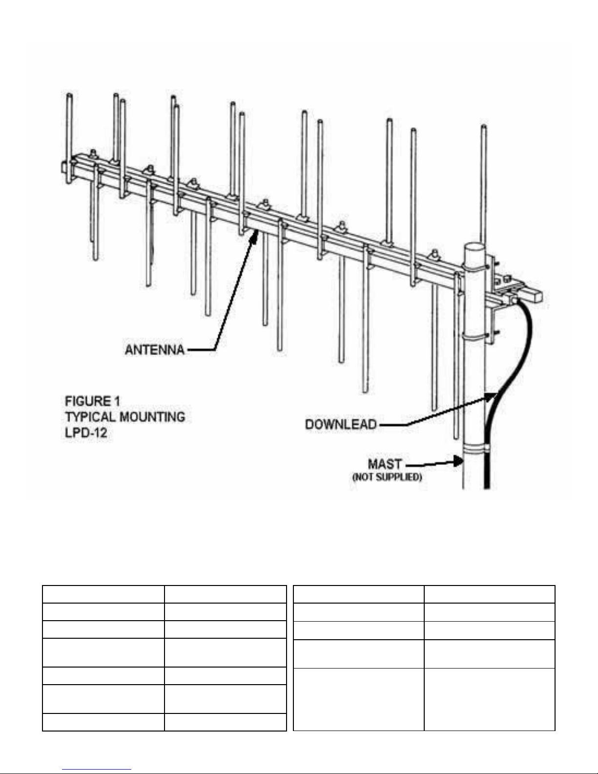
The LPD-12 225-400 is a twelve element log periodic dipole antenna covering the frequency range
225 MHz-400 MHz. The antenna is designed for cantilever rear mounting to masts up to 3” O.D. to
provide vertical polarization.
Theory of operation.
The antenna is comprised of twelve dipole elements connected to a parallel pair of 1 1/4” aluminum crossarms that form the antenna transmission line. To accomplish end fire log periodic operation the elements are tapered from the front of the antenna to the back and successive dipole
halves are transposed along the antenna transmission line. An internal cable in one of the
crossarm sections functions as a balun to convert the balanced 50 ohm input at the front of the antenna to 50 ohm unbalanced coaxial “N” type connector mounted at the rear of the antenna. This
internal “balun” effectively chokes off the surface currents normally associated with a balanced
feed and eliminates transmission line radiation.
The entire antenna is maintained at d.c. ground potential through the grounding of the crossarms
at the rear of the antenna. A ground wire attended to the crossarm mounting or the cable fitting
will drain off static build up and provide lightning protection.
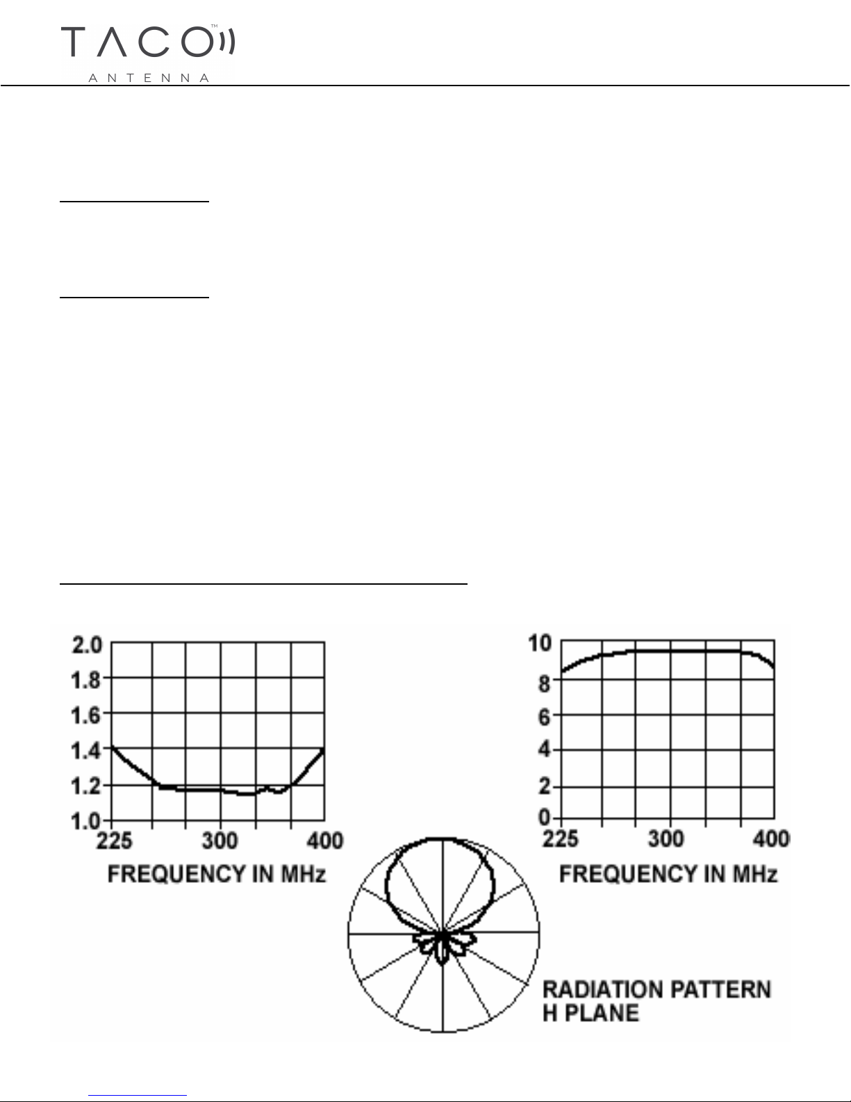
ELECTRICAL CHARACTERISTICS (TYPICAL)
Page 2
ELECTRICAL MECHANICAL
FREQ. RANGE (MHz) 225-400 MHz
GAIN (dBi, Min.) 8.5
POLARIZATION VERTICAL
HPBW (Nom., deg) E-PLANE 55 DEG.
H-PLANE 75 DEG.
VSWR (MAX.) 1.5:1
TERMINAL: TYPE
: IMPEDANCE
MAX. POWER 500 WATTS
“N”
50 OHM
LENGTH 79.50 IN. (201.93 CM)
LONGEST ELEMENT 26.75 IN. (67.95 CM)
WEIGHT 14 LBS. (6.35 KG)
MOUNT
(MAST DIA.)
WINDLOADING
(85 Knot with
1/2 in. (1.27 cm)
Radial Ice
Up to 3.00 in. (7.62 cm)
109 lbs. (49.44 kg)
Page 3

Antenna Mounting
1. Loosely assemble the two 3/8” diameter U-bolts into the mounting clamps.
2. Slide the U-bolts over the end of the support mast, orient the antenna to the desired azimuth
and tighten U-bolts securely.
Downlead.
1. RG-213/U cable is recommended for the downlead.
2. Assemble a UG-21B/U connector to the cable.
3. Thread the connector onto the antenna connector.
4. Loop the cable up and around to the support mast. Cable may either be routed down the outside of the mast or through the mast.
SAFETY PRECAUTIONS
To protect your antenna and receiver from lightning, you should ground your equipment.
1. To ground the antenna attach a ground wire under the head of the 3/8-16 x 3 1/4 in. long hex
head screw at the mounting bracket (see Figure 2). Run the ground wire down the mast to a
ground rod driven at least 4 feet into the ground.
2. Keep the antenna and cable a safe distance from any power lines.
Page 4

Horizontal Mounting Bracket Detail
Page 5

LPD-12 REPLACEMENT PARTS
ITEM DESCRIPTION QTY/UNIT PART NUMBER
1 Crossarm Assembly 1 28829-501
2 Element 6.85 in. 2 21910-040
3 Element 7.30 in. 2 21910-041
4 Element 7.80 in. 2 21910-042
5 Element 8.35 in. 2 21910-043
6 Element 8.95 in. 2 21910-044
7 Element 9.60 in. 2 21910-045
8 Element 10.30 in. 2 21910-046
9 Element 11.05 in. 2 21910-047
10 Element 11.85 in. 2 21910-048
11 Element 12.80 in. 2 21910-049
12 Element 13.75 in. 2 21910-050
13 Element 14.85 in. 2 21910-051
14 Mounting Bracket, Vertical 2 28859-501
15 U-Bolt 2 20041-001
16 Mounting Bracket, Horizontal 1 28860-501
*Spare hardware for these items is included for the installers convenience.
 Loading...