

Page 1

505-010-2
Application Guide
VPU2 Air Control – Pressure Independent Multi-Zone
Self-Contained Interoperable Controller Model UCP-1
SUPERSEDES: January 16, 2013
Plant ID: 001-4026
Table of Contents
VPU2 . . . . . . . . . . . . . . . . . . . . . . . . . . . . . . . . . . . . . . 3
Overview . . . . . . . . . . . . . . . . . . . . . . . . . . . . . . . . . 3
Features. . . . . . . . . . . . . . . . . . . . . . . . . . . . . . . . . . 3
Purpose of This Guide . . . . . . . . . . . . . . . . . . . . . . . . . 3
Representations and Warranties . . . . . . . . . . . . . . . . . 4
Applicable Documentation . . . . . . . . . . . . . . . . . . . . . . 4
Installation Instructions . . . . . . . . . . . . . . . . . . . . . . . . . 5
General . . . . . . . . . . . . . . . . . . . . . . . . . . . . . . . . . .5
Static Electricity . . . . . . . . . . . . . . . . . . . . . . . . . . . . 5
FCC Compliance . . . . . . . . . . . . . . . . . . . . . . . . . . . 5
Before Installing . . . . . . . . . . . . . . . . . . . . . . . . . . . . . . 5
About this Document . . . . . . . . . . . . . . . . . . . . . . . . 5
Inspecting the Equipment . . . . . . . . . . . . . . . . . . . . 5
What is Not Included with this Equipment . . . . . . . . 6
Equipment Location . . . . . . . . . . . . . . . . . . . . . . . . .6
Selecting a Power Source . . . . . . . . . . . . . . . . . . . . 6
Installation . . . . . . . . . . . . . . . . . . . . . . . . . . . . . . . . . . 6
Mounting the Device . . . . . . . . . . . . . . . . . . . . . . . .6
Routing Cabling to the Device . . . . . . . . . . . . . . . . . 7
Grounding the Device . . . . . . . . . . . . . . . . . . . . . . .7
Wiring Information . . . . . . . . . . . . . . . . . . . . . . . . . . . . 8
Connecting Input Devices . . . . . . . . . . . . . . . . . . . 10
Connecting Output Devices . . . . . . . . . . . . . . . . . .11
Other Connections . . . . . . . . . . . . . . . . . . . . . . . . . 12
Protocol . . . . . . . . . . . . . . . . . . . . . . . . . . . . . . . . . 13
Specifications . . . . . . . . . . . . . . . . . . . . . . . . . . . . . . . 13
Electrical . . . . . . . . . . . . . . . . . . . . . . . . . . . . . . . . 13
Mechanical. . . . . . . . . . . . . . . . . . . . . . . . . . . . . . . 14
Application Description . . . . . . . . . . . . . . . . . . . . . . . . 15
Sequence of Operation. . . . . . . . . . . . . . . . . . . . . . . . 17
Occupancy State . . . . . . . . . . . . . . . . . . . . . . . . . . 17
Operational Mode . . . . . . . . . . . . . . . . . . . . . . . . . 18
Setpoint Calculations . . . . . . . . . . . . . . . . . . . . . . .20
Supply Air Setpoint Reset Curve . . . . . . . . . . . . . . 20
Outside Air Temperature Lockouts . . . . . . . . . . . .21
Heating Sequence . . . . . . . . . . . . . . . . . . . . . . . . . 22
EFFECTIVE: April 29, 2014
Cooling Sequence . . . . . . . . . . . . . . . . . . . . . . . . . 25
Economizer Operation. . . . . . . . . . . . . . . . . . . . . . 29
Dehumidification . . . . . . . . . . . . . . . . . . . . . . . . . . 30
Fan Operation . . . . . . . . . . . . . . . . . . . . . . . . . . . . 30
Static Pressure Control . . . . . . . . . . . . . . . . . . . . . 30
Soft Start Ramping . . . . . . . . . . . . . . . . . . . . . . . . 31
Fan Proof. . . . . . . . . . . . . . . . . . . . . . . . . . . . . . . . 31
VPU2 and VAVI Communications . . . . . . . . . . . . . 31
Power On/Reset Delay . . . . . . . . . . . . . . . . . . . . . 32
Supply Air Temperature Monitoring . . . . . . . . . . . . 32
Smoke Detection . . . . . . . . . . . . . . . . . . . . . . . . . . 32
Mixed Air Low Limit Detection . . . . . . . . . . . . . . . . 32
Filter Status . . . . . . . . . . . . . . . . . . . . . . . . . . . . . . 33
Indoor Air Quality. . . . . . . . . . . . . . . . . . . . . . . . . . 33
Real Time Clock (RTC) . . . . . . . . . . . . . . . . . . . . . 33
Local Backup Schedule . . . . . . . . . . . . . . . . . . . . . 33
Runtime Accumulation. . . . . . . . . . . . . . . . . . . . . . 34
Alarms and Events. . . . . . . . . . . . . . . . . . . . . . . . . 34
Automatic Configuration . . . . . . . . . . . . . . . . . . . . 34
Controller Identification . . . . . . . . . . . . . . . . . . . . . . . 34
Inputs. . . . . . . . . . . . . . . . . . . . . . . . . . . . . . . . . . . 35
Outputs . . . . . . . . . . . . . . . . . . . . . . . . . . . . . . . . . 35
Configuration . . . . . . . . . . . . . . . . . . . . . . . . . . . . . 36
Alarms . . . . . . . . . . . . . . . . . . . . . . . . . . . . . . . . . . 42
Troubleshooting . . . . . . . . . . . . . . . . . . . . . . . . . . . . . 43
Diagnostic LEDs . . . . . . . . . . . . . . . . . . . . . . . . . . 43
Troubleshooting Tips . . . . . . . . . . . . . . . . . . . . . . . 44
© 2014 Taco Electronic Solutions, Inc. 1
Page 2

iWorx® VPU2
THIS PAGE LEFT BLANK INTENTIONALLY
2 505-010-2, Effective: April 29, 2014
© 2014 Taco Electronic Solutions, Inc.
Page 3

iWorx® VPU2
VPU2
The VPU2 is a self-contained microprocessor-based controller for one Variable Air Volume (VAV) package unit. Applications include VAV package units with up to four stages of cooling, or a floating point control valve or a modulated output (valve or variable speed circulator) two stages of heating, or a floating point control valve or a modulated output
(valve or variable speed circulator) an economizer, and a variable speed fan. The VPU2 is designed for integrated networked operation with the iWorx® Local Control Interface (LCI) and up to 56 VAV terminal unit controllers.
Overview
Digital inputs are provided for fan status, mixed air low limit indication, smoke detector, and filter status. Analog inputs
are provided for mixed air temperature, return air humidity, supply air temperature and supply duct static pressure. An
indoor air quality (IAQ) input can be configured for analog or digital operation.
The VPU2 incorporates digital outputs in the form of triacs for fan start/stop, four cooling stages, two heating stages
and a two-position economizer. In addition, two analog outputs are provided to control a modulated economizer and
variable speed fan drive.
The controller is based on the LONWORKS® networking technology. The controller can be networked to a higher-level
control system for monitoring and control applications.
Features
• Four stages of cooling, or floating point valve control or a modulated output (valve or variable speed circulator)
• Two stages of heating, or floating-point valve control or a modulated output (valve or variable speed circulator)
• Dehumidification
• Modulated fan speed
• Digital or modulated economizer
• Economizer enabled based on enthalpy calculations or dry bulb
• Minimum cycle timers for stages
• Runtime accumulation for heating, cooling and fan
• Local backup schedule
• Maximum of 56 zones (VAV boxes)
• Supply air temperature safety limits
• Time proportioned control of the staged outputs to reduce cycling
• Proportional + Integral control of the modulated economizer, modulated heating, modulated cooling, and static
pressure
• Mixed air low limit protection, filter status, fan proof, freeze stat, and smoke detection inputs
• IAQ compensation based on IAQ alarm input or zone controller alarm
• Outside Air Temperature cutoffs
• Automatic morning warm-up sequence
•LONWORKS interface to building automation systems
• Automatic configuration with the LCI
• Alarm/Event reporting
PURPOSE OF THIS GUIDE
The iWorx® VPU2 Application Guide provides application information for the VPU2 Controller.
The reader should understand basic HVAC concepts, intelligent environmental control automation, and basic LON-
WORKS networking and communications. This Application Guide is written for:
• Users who engineer control logic
505-010-2, Effective: April 29, 2014 3
© 2014 Taco Electronic Solutions, Inc.
Page 4

iWorx® VPU2
• Users who set up hardware configuration
• Users who change hardware or control logic
• Technicians and field engineers of Taco Electronic Solutions, Inc.
REPRESENTATIONS AND WARRANTIES
This Document is subject to change from time to time at the sole discretion of Taco Electronic Solutions, Inc. All
updates to the Document are available at www.taco-hvac.com. When installing this product, it is the reader’s responsibility to ensure that the latest version of the Document is being used.
iWorx® products shall only be used for the applications identified in the product specifications and for no other purposes. For example, iWorx® products are not intended for use to support fire suppression systems, life support systems, critical care applications, commercial aviation, nuclear facilities or any other applications where product failure
could lead to injury to person, loss of life, or catastrophic property damage and should not be used for such purposes.
Taco Electronic Solutions, Inc. will not be responsible for any product or part not installed or operated in conformity with
the Document and instructions or which has been subject to accident, disaster, neglect, misuse, misapplication, inadequate operating environment, repair, attempted repair, modification or alteration, or other abuse. For further information, please refer to the last page of this Document for the company’s Limited Warranty Statement, which is also issued
with the product or available at www.taco-hvac.com.
APPLICABLE DOCUMENTATION
See the table below for additional documentation that may be applicable to this controller.
Description Audience Purpose
iWorx® VPU2 Application Guide,
Document No. 505-010 (this document)
iWorx® LCI Application Guide, Document No. 505-002
iWorx® VAV Application Guide, Document No. 505-011
http://www.iWorxWizard.com – Application Engineers
Additional
Documentation
– Application Engineers
– Installers
– Service Personnel
– Start-up Technicians
– End user
– Application Engineers
– Installers
– Service Personnel
– Start-up Technicians
– End user
– Application Engineers
– Installers
– Service Personnel
– Start-up Technicians
– End user
– Wholesalers
– Contractors
LonWorks FTT-10A Free Topology Transceiver User’s Guide, published by Echelon Corporation. It provides specifications and user instructions for the FTT-10A Free Topology Transceiver. See also: www.echelon.com/support/documentation/manuals/transceivers.
Provides instructions for setting up and using
the iWorx® VPU2 controller.
Provides instructions for setting up and using
the iWorx® Local Control Interface.
Provides instructions for setting up and using
the iWorx® VAV Series controller.
An on-line configuration and submittal package
generator based on user input. Automatically
generates bill of materials, sequence of operations, flow diagrams, wiring diagrams, points
and specifications.
4 505-010-2, Effective: April 29, 2014
© 2014 Taco Electronic Solutions, Inc.
Page 5

iWorx® VPU2
INSTALLATION INSTRUCTIONS
General
CAUTION: This symbol is intended to alert the user to the presence of important installation and mainte-
nance (servicing) instructions in the literature accompanying the equipment.
CAUTION: Risk of explosion if battery is replaced by an incorrect type. Contains lithium type battery; dispose of properly.
WARNING: Electrical shock hazard. Disconnect ALL power sources when installing or servicing this
equipment to prevent electrical shock or equipment damage.
Make all wiring connections in accordance with these instructions and in accordance with pertinent national and local
electrical codes. Use only copper conductors that are suitable for 167 °F (75 °C).
Static Electricity
Static charges produce voltages that can damage this equipment. Follow these static electricity precautions when handling this equipment.
• Work in a static free area.
• Touch a known, securely grounded object to discharge any charge you may have accumulated.
• Use a wrist strap when handling printed circuit boards. The strap must be secured to earth ground.
FCC Compliance
This equipment has been tested and found to comply with the limits for a Class A digital device, pursuant to Part 15 of
the FCC rules. These limits are designed to provide reasonable protection against harmful interference. This equipment can radiate radio frequency energy and, if not installed and used in accordance with the instructions, may cause
harmful interference to radio communications. However, there is no guarantee that interference will not occur in a particular installation. If this equipment does cause harmful interference to radio or television reception, which can be
determined by turning the equipment off and on, the user is encouraged to try to correct the interference by one or
more of the following measures:
• Reorient or relocate the receiving antenna.
• Increase the separation between the equipment and the receiver.
• Connect the equipment to a power source different from that to which the receiver is connected.
• Consult the equipment supplier or an experienced radio/TV technician for help.
You are cautioned that any changes or modifications to this equipment not expressly approved in these instructions
could void your authority to operate this equipment in the United States.
BEFORE INSTALLING
About this Document
The instructions in this manual are for the VPU2 controller, which supporst one Variable Air Volume package unit.
Inspecting the Equipment
Inspect the shipping carton for damage. If damaged, notify the carrier immediately. Inspect the equipment for damage.
Return damaged equipment to the supplier.
505-010-2, Effective: April 29, 2014 5
© 2014 Taco Electronic Solutions, Inc.
Page 6

iWorx® VPU2
What is Not Included with this Equipment
• A power source for the equipment electronics and peripheral devices.
• Tools necessary to install, troubleshoot and service the equipment.
• The screws or DIN rail needed to mount the device.
• Peripheral devices, such as sensors, actuators, etc.
• Cabling, cabling raceway, and fittings necessary to connect this equipment to the power source, FTT-10A network
and peripheral devices.
Equipment Location
Abide by all warnings regarding equipment location provided earlier in this document.
Optimally, the equipment should be installed within a secure enclosure.
If the equipment is to be installed outdoors, it must be contained within a protective enclosure. The enclosure must
maintain internal temperature and humidity within the ranges specified for this equipment.
The equipment must be installed within 500 feet of all input peripherals (smoke detectors, sensors, etc.) that are connected to the equipment.
Selecting a Power Source
This equipment requires a UL recognized Class 2 external power source (not supplied) to operate. The controller
power input requires a voltage of 24 Volts AC.
To calculate power source current requirements, add the power consumption of all peripheral devices to that of the
controller.
The controller and sensor power supplies can use the same power source. If both are using the same power source,
the loads must have EMF protection. This protection can be integral to the load, or installed in the 24 VAC wiring across
the load’s coil.
To provide necessary RFI and transient protection, the controller’s ground (GND) pin (T40) must be connected to earth
ground or the earth ground of the packaged unit’s enclosure ground. Failure to properly ground the controller may
cause it to exceed FCC limits. Excessive noise could also produce inaccurate sensor data. The power source must be
capable of operating with this connection to ground.
INSTALLATION
Warning: Electrical shock hazard. To prevent electrical shock or equipment damage, disconnect ALL
power sources to controllers and loads before installing or servicing this equipment or modifying any wiring.
Mounting the Device
1.Select a mounting location. Enclosure mounting is recommended.
2.Hold the controller on the panel you wish to mount it on. With a marker or pencil mark the mounting locations on
the panel.
3.Using a small drill bit pre-drill the mounting holes.
4.Using two #6 pan head screws, mount the controller to the panel.
5.Wire the controller (See Routing Cabling to the Device).
6 505-010-2, Effective: April 29, 2014
© 2014 Taco Electronic Solutions, Inc.
Page 7
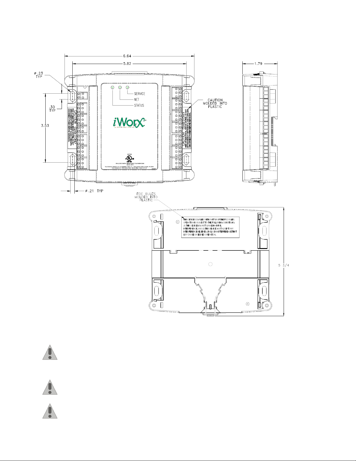
Figure 1: Mounting Dimensions
iWorx® VPU2
Routing Cabling to the Device
Cabling used to connect the power source and cabling used to connect the FTT-10A network must remain
separated within the control enclosure and wiring conduit.
Grounding the Device
The ground terminal (T40) must be securely connected to earth ground. Failure to properly ground this
equipment will result in improper operation. Improper grounding may also increase the risk of electrical
shock and may increase the possibility of interference with radio/TV reception.
For best performance, connect the power supply common terminal (T38) to the same external point as the
ground terminal (T40).
505-010-2, Effective: April 29, 2014 7
© 2014 Taco Electronic Solutions, Inc.
Page 8
iWorx® VPU2
WIRING INFORMATION
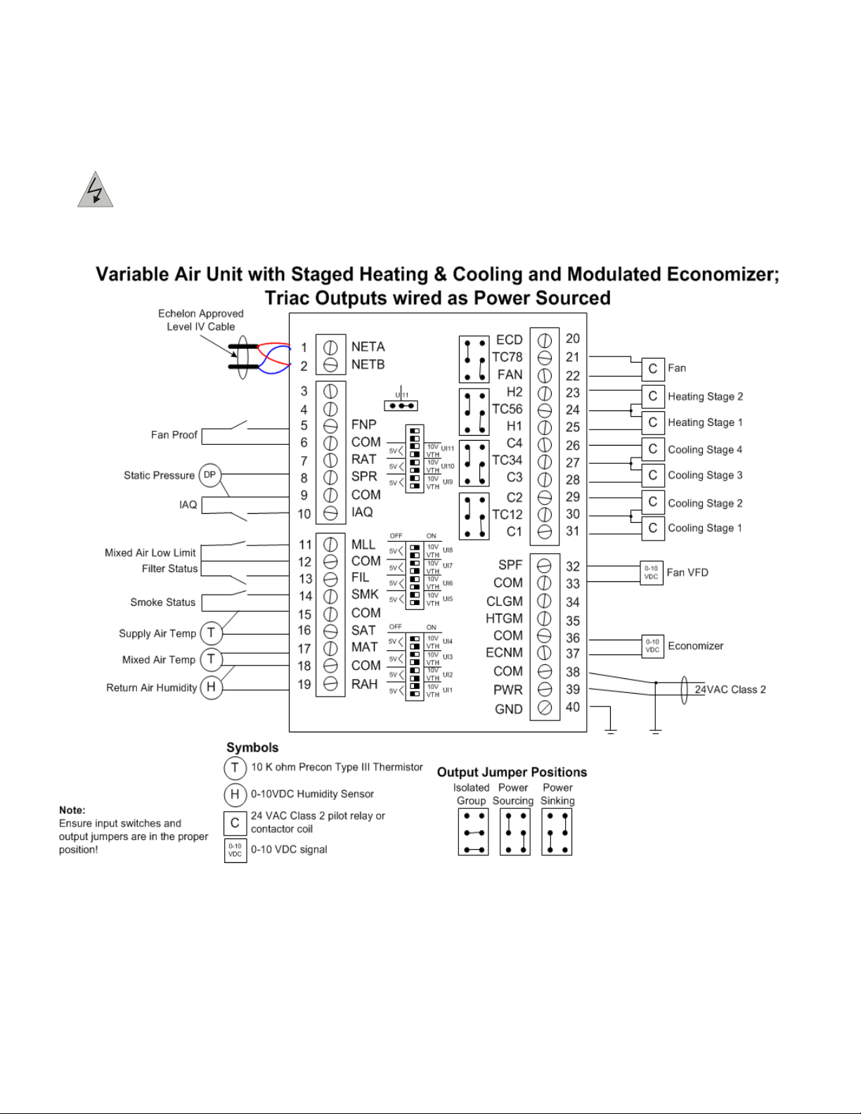
WARNING: Terminals 6, 9, 12, 15, and 18 are connected internally on all VPU2 controllers. Disconnect
ALL power sources when installing or servicing this equipment to prevent electrical shock or equipment
damage.
Figure 2: Typical VPU2 Wiring - Example A
8 505-010-2, Effective: April 29, 2014
© 2014 Taco Electronic Solutions, Inc.
Page 9
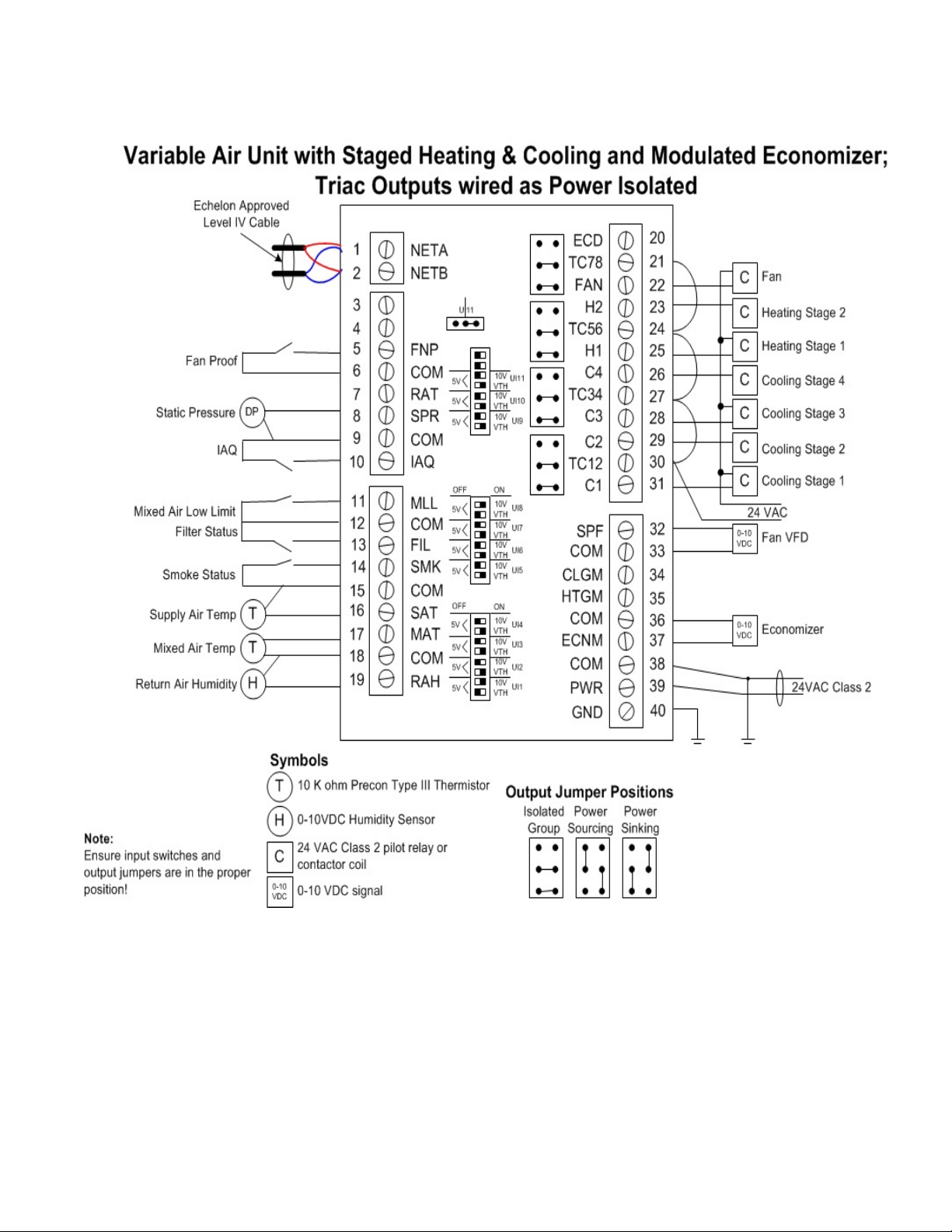
Figure 3: Typical VPU2 Wiring - Example B
iWorx® VPU2
505-010-2, Effective: April 29, 2014 9
© 2014 Taco Electronic Solutions, Inc.
Page 10
iWorx® VPU2
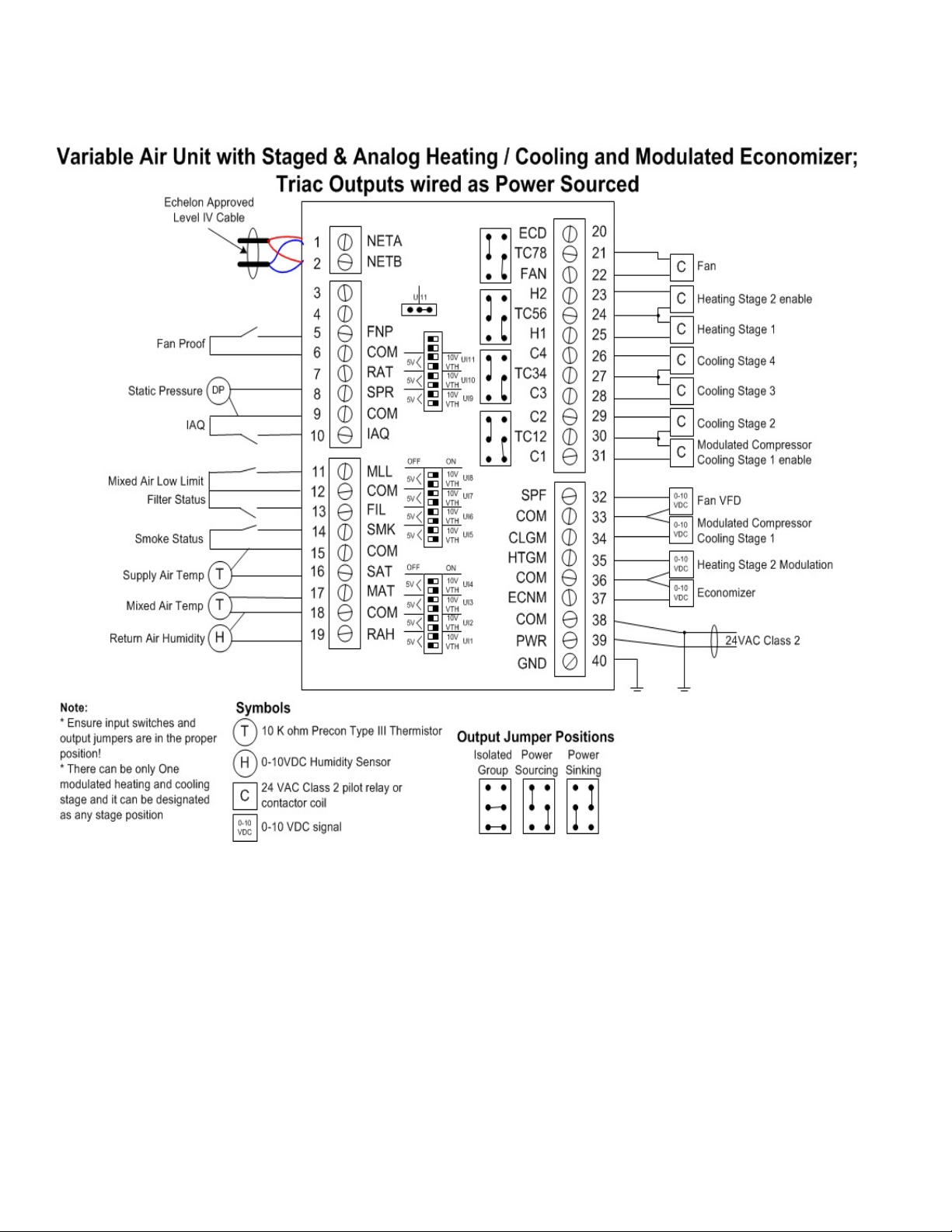
Figure 4: Typical VPU2 Wiring - Example C
Connecting Input Devices
Return Humidity (RAH)
To connect the Return Air Humidity sensor to the unit, connect the positive wire from the sensor to RAH (T19) and the
other wire to the adjacent common (T18). The sensor must be of the 0-10 Volt type.
If global indoor air humidity readings are being provided over the network, it is not necessary to attach a return air
humidity sensor directly to the VPU2.
Mixed Air (MAT)
To connect the Mixed Air thermistor to the unit, attach one wire from the thermistor to MAT (T17) and the other wire to
the adjacent common (T18). The thermistor used must be 10K Precon Type III.
10 505-010-2, Effective: April 29, 2014
© 2014 Taco Electronic Solutions, Inc.
Page 11

iWorx® VPU2
Supply Air (SAT)
To connect the Supply Air thermistor to the unit, attach one wire from the thermistor to SAT (T16) and the other wire to
the adjacent common (T15). The thermistor used must be 10K Precon Type III.
Smoke Detector (SMK)
To connect the smoke detector switch to the digital input, attach one wire of the contact to SMK (T14) and the other
wire to the adjacent common (T15). This must be a dry contact normally open switch. This input is for indication only. A
separate smoke detector should be wired into a fire alarm system if the generation of a fire alarm is required.
Filter Status (FIL)
To connect the filter switch to the digital input, attach one wire of the contact to FIL (T13) and the other wire to the adjacent common (T12).
Mixed Air Low Limit (MLL)
This must be a dry contact normally open switch. To connect the low limit indication switch to the digital input, attach
one wire of the contact to MLL (T11) and the other wire to the adjacent common (T12). This must be a dry contact normally open switch.
Indoor Air Quality (IAQ)
This must be a dry contact normally-open switch. To connect the digital CO2 level sensor to the unit, attach one wire
from the sensor to IAQ (T10) and the other wire to the adjacent common (T9). For a digital sensor, this must be a dry
contact, normally closed switch. For an analog sensor, it must be of the 0-10V type.
Static Pressure (SPR)
To connect the static pressure sensor to the analog input, attach the positive wire from the sensor to SPR (T8) and the
other wire to the adjacent common (T9). The sensor must be analog, 0 to 10 volt type.
Return Air Temperature (RAT)
To connect the return air temperature thermistor to the analog input, attach one wire of the sensor to RAT (T7) and the
other wire to the adjacent common (T6).
Fan Proof (FNP)
To connect the fan proof switch to the digital input, attach one wire of the contact to FNP (T5) and the other wire to the
adjacent common (T6). This must be a dry contact, normally closed switch. If you are not providing a fan proof input, T5
and T6 must be shorted (jumpered) together.
Connecting Output Devices
Modulated Economizer (ECNM)
The modulated economizer output can be set to 0-10 V max through the control logic. Connect the positive wire from
the damper actuator to ECNM (T37) and the other wire to the adjacent common (T36). See preceding figures for
details.
Modulated Heating (HTGM)
The modulated heating output can be set to 0-10 V max through the control logic. Connect the positive wire from the
heating output to HTGM (T35) and the other wire to COM (T36). See preceding figures for details.
Modulated Cooling (CLGM)
The modulated cooling output can be set to 0-10 V max through the control logic. Connect the positive wire from the
cooling output to CLGM (T34) and the other wire to COM (T33). See preceding figures for details.
505-010-2, Effective: April 29, 2014 11
© 2014 Taco Electronic Solutions, Inc.
Page 12

iWorx® VPU2
Modulated Static Pressure Fan (SPF)
The modulated static pressure fan output can be set to 0-10 V max through the control logic. Connect the positive wire
from the fan output to SPF (T32) and the other wire to COM (T33). See preceding figures for details.
Cooling Stage 1 or Cooling Floating Point Valve Open (C1)
The cooling stage output must be connected to a 24 VAC pilot relay if the load is greater than 1 Amp. See preceding
figures for details. If the load is less than 1 Amp, connect cooling stage 1 to C1 (T31) and TC12 (T30). For control of a
floating point valve, connect C1 as the valve open signal.
Cooling Stage 2 or Cooling Floating Point Valve Close (C2)
The cooling stage output must be connected to a 24 VAC pilot relay if the load is greater than 1 Amp. See preceding
figures for details. If the load is less than 1 Amp, connect cooling stage 2 to C2 (T29) and TC12 (T30). For control of a
floating point valve, connect C2 as the valve close signal.
Cooling Stage 3 (C3)
The cooling stage output must be connected to a 24 VAC pilot relay if the load is greater than 1 Amp. See preceding
figures for details. If the load is less than 1 Amp, connect to C3 (T28) and TC34 (T27).
Cooling Stage 4 (C4)
The cooling stage output must be connected to a 24 VAC pilot relay if the load is greater than 1 Amp. See preceding
figures for details. If the load is less than 1 Amp, connect to C4 (T26) and TC34 (T27).
Heating Stage 1 or Heating Floating Point Valve Open (H1)
The heating stage output must be connected to a 24 VAC pilot relay if the load is greater than 1 Amp. See preceding
figures for details. If the load is less than 1 Amp, connect heating stage 1 to H1 (T25) and TC56 (T24). For control of a
floating point heating valve, connect H1 (T25) as the valve open signal. TC56 (T24) is the common.
Heating Stage 2 or Heating Floating Point Valve Close (H2)
The heating stage output must be connected to a 24 VAC pilot relay if the load is greater than 1 Amp. See preceding
figures for details. If the load is less than 1 Amp, connect heating stage 2 to H2 (T23) and TC56 (T24). For control of a
floating point heating valve, connect H2 (T23) as the valve close signal. TC56 (T24) is the common.
Fan (FAN)
The fan output must be connected to a 24 VAC pilot relay if the load is greater than 1 Amp. See preceding figures for
details. If the load is less than 1 Amp, connect the fan to FAN (T22) and TC78 (T21).
Two Position Economizer (ECD)
The two-position economizer output must be connected to a 24 VAC pilot relay if the load is greater than 1 Amp. See
preceding figures for details. If the load is less than 1 Amp, connect the economizer to ECD (T20) and TC78 (T21).
Other Connections
Network (LON)
Network wiring must be twisted pair. One network wire must be connected to terminal NETA (T1) and the other network
wire must be connected to terminal NETB (T2). Polarity is not an issue since an FTT-10A network is used for communications.
Power (PWR)
Connect one output wire from a 24 VAC power supply to PWR (T39) and the other output wire from the power supply to
the adjacent common terminal (T38). T38 must be connected to earth ground.
12 505-010-2, Effective: April 29, 2014
© 2014 Taco Electronic Solutions, Inc.
Page 13

iWorx® VPU2
Ground (GND)
Terminal GND (T40) must be connected to earth ground. Failure to properly ground this equipment will
result in improper operation. Improper grounding may also increase the risk of electrical shock, and may
increase the possibility of interference with radio and TV reception.
Protocol
The VPU2 is based on the LONWORKS® networking technology and can be networked to a higher-level control system
for monitoring and control applications. For additional information on the Protocol reference the LonWorks FTT-10A
Free Topology Transceiver User's Guide, published by the Echelon Corporation.
SPECIFICATIONS
Electrical
Inputs
• Cabling: twisted shielded pair, 18 AWG recommended—500 feet max. (152 meters)
• Resolution: 10 bit
Mixed Low Limit, Filter Status, Smoke Detect, Local IAQ Alarm
• Dry Contact
• Normally Open
•5 Volts DC Max
Fan Proof
• Dry Contact
• Normally Closed
•5 Volts DC Max
Return Air Humidity, Static Pressure
• 0 - 10 Volts DC
Mixed Air Temperature, Supply Air Temperature, Return Air Temperature
• Precon Type III 10K thermistor
Outputs
Cooling Stages 1, 2, 3, & 4; Heating Stages 1 & 2; Fan Start/Stop; Two-position Economizer
•24 Volts AC
• 1A @ 50C, 0.5A @ 60C, limited by the Class 2 supply rating
Modulated Economizer, Modulated Static Pressure Fan
• 0-10 Volts DC
• 2K Ohm minimum load
• 8 bit resolution
Power
Power Requirements
• 24VAC (20VAC to 28VAC), requires an external Class 2 supply
Power Consumption
• 7.2W with no external loads, maximum limited by the Class 2 supply rating
505-010-2, Effective: April 29, 2014 13
© 2014 Taco Electronic Solutions, Inc.
Page 14
iWorx® VPU2
Recommended Sensor Wire
Cable Type Pairs Details Taco Catalog No.
18AWG 1 Stranded Twisted Shielded Pair, Plenum WIR-018
FTT-10A Network
• Speed: 78KBPS
• Cabling: Maximum node-to-node distance: 1312 feet (400 meters)
• Maximum total distance: 1640 feet (500 meters)
Cable Type Pairs Details Taco Catalog No.
Level 4 22AWG (0.65mm) 1 Unshielded, Plenum, U.L. Type CMP WIR-022
For detailed specifications, refer to the FTT-10A Free-Topology Transceiver User’s Guide published by Echelon Corporation (www.echelon.com/support/documentation/manuals/transceivers).
Mechanical
Housing
• Dimensions: 5.55” (141mm) high, 6.54” (166 mm) wide, 1.75” deep (44 mm)
• ABS
Weight
• Controller Weight: 0.70 pounds (0.32 kilograms)
• Shipping Weight: 1.0 pounds (0.46 kilograms)
Electronics
• Processor: 3150 Neuron 10 MHz
• Flash: 48 Kilobytes
• SRAM: 8 Kilobytes
• Termination: 0.197” (5.0 mm) Pluggable Terminal Blocks, 14-22 AWG
Environmental
• Temperature: 32 °F to 140 °F (0 °C to 60 °C)
• Humidity: 0 to 90%, non-condensing
Agency Listings
• UL Listed for US and Canada, Energy Management Equipment PAZX and PAZX7.
Agency Compliances
• FCC Part 15 Class A
14 505-010-2, Effective: April 29, 2014
© 2014 Taco Electronic Solutions, Inc.
Page 15

iWorx® VPU2
APPLICATION DESCRIPTION
The VPU2 is a Variable Air Volume (VAV) package unit controller for controlling supply air temperature and supply air
duct static pressure. Figure 5 and Figure 6 illustrate typical VPU2 applications. The VPU2 operates in conjunction with
up to 56 VAVI zone controllers. Control is achieved by modulating the economizer position and sequencing the heating
and cooling stages based on the current supply air temperature requirements. In addition, the VPU2 controls the supply fan speed to maintain a supply duct static pressure setpoint.
Figure 5: VPU2 Application with Staged Heating & Cooling and Modulated Economizer
The VPU2 controls the starting and stopping of the supply air fan. During the occupied and warm-up periods, the fan
runs continuously. The fan cycles on during the unoccupied periods when a zone is in extended occupancy or when
there is a call for emergency heating. The fan speed control operates to maintain a configurable system static pressure
setpoint. Fan speed is calculated by a Proportional + Integral (P+I) control loop based on the measured static pressure
and setpoint. As the pressure increases above the pressure setpoint, the fan speed output is throttled back. As the
pressure decreases below the pressure setpoint, the output is increased.
The enthalpies of the outside and inside air are calculated periodically. A comparison is performed to determine if “free
cooling” is available. If “free cooling” is available, the economizer is enabled. Free cooling can also be enabled based
on a dry-bulb comparison of the outdoor air temperature and indoor temperature. The system can use either a twoposition or modulated economizer. If a two-position economizer is employed, it is energized when there is a call for
cooling. It is used as the first stage of cooling to take advantage of the energy savings. The two-position economizer
output is off when the modulating economizer feature is disabled.
505-010-2, Effective: April 29, 2014 15
© 2014 Taco Electronic Solutions, Inc.
Page 16

iWorx® VPU2
If a modulated economizer is employed and “free cooling” is available the modulated economizer position is calculated
by a Proportional + Integral (P+I) control loop. The control is based on the mixed air temperature and setpoint. As the
temperature increases above the mixed air setpoint the economizer is modulated open. The economizer is modulated
closed as the temperature decreases below the mixed air setpoint. The economizer is modulated to its minimum position when the economizer is disabled. The economizer can optionally be disabled during the unoccupied periods.
When free cooling is available, mechanical cooling will not be enabled until the economizer is fully open (100%) for
three minutes at which time mechanical cooling will be enabled. This will help in preventing low suction and icing of the
cooling coils.
Either type of economizer can be disabled during unoccupied periods.
The VPU2 operates in one of four states: morning warm-up/cool-down, occupied, unoccupied, or shutdown. A host
device on the network determines the active operating mode. An optional backup schedule is provided for cases when
the host device is not available. The operating state determines if the VPU2 is in heating mode or cooling mode.
Figure 6: VAV Zone Control System
Cooling is accomplished through control of up to four stages of cooling, or one floating point cooling valve or control of
one analog cooling output (valve or variable speed circulator).
When the operating mode is cooling (occupied and extended occupancy), the cooling stages are sequenced on and off
with a time-proportioned control algorithm to minimize excessive cycling. The sequencing is based on the supply air
temperature and cooling setpoint. The cooling stages are interlocked with the economizer control. If the economizer is
enabled, the cooling stages do not sequence on until the economizer has reached its open position.
If configured for modulated analog output the cooling output position is calculated by a P + I control loop based on the
supply temperature and the cooling setpoint. As the temperature increases above the cooling setpoint, the cooling output will be modulated open. The cooling output will be modulated closed as the temperature decreases below the cooling setpoint.
If configured for a floating point valve control the cooling valve is calculated by a P + I control loop based on the supply
temperature and cooling setpoint. As the temperature increases above the cooling setpoint, the valve will be modulated
open. The valve will be modulated closed as the temperature decreases below the cooling setpoint.
Heating is accomplished through control of up to two stages of electric heating, or control of one floating point heating
valve or control of one analog output.
When the operating mode is heating (morning warm-up), the heating stages are sequenced on and off with a time-proportioned control algorithm to minimize excessive cycling. The sequencing is based on the supply air temperature and
heating setpoint. Heating can also be controlled with a floating-point control of a valve.
The heating output position is calculated by a P +I control loop based on the supply temperature and the heating setpoint. As the temperature decreases below the heating setpoint, the heating output will be modulated open. The heating output will be modulated closed as the temperature increases above the heating setpoint.
16 505-010-2, Effective: April 29, 2014
© 2014 Taco Electronic Solutions, Inc.
Page 17

iWorx® VPU2
If configured for a floating point valve control the heating valve is calculated by a P + I control loop based on the supply
temperature and cooling setpoint. As the temperature decreases below the heating setpoint, the valve will be modulated open. The valve will be modulated closed as the temperature increases above the heating setpoint.
In both the heating and cooling modes the supply air temperature setpoint may be reset by the zone demand.
The VPU2 can also monitor the supply air temperature to determine if the heating and cooling are operating properly.
During the cooling mode, if the supply air temperature fails to drop below the cooling operational limit after a pre-determined time period, a cooling failed alarm is reported to the LCI.
During the heating mode, if the supply air temperature fails to rise above the heating operational limit after a pre-determined time period, a heating failed alarm is reported to the LCI.
As a safety device, the controller can optionally monitor the supply air temperature to determine if the heating stages
have failed on. If the supply air temperature rises above the heating high limit setpoint, the fan energizes. If the supply
air temperature does not drop below the setpoint after a pre-programmed time delay, the fan speed is overridden off. A
heating high limit exceeded alarm is reported to the LCI and all of the zone controllers.
An indoor air quality input is provided. If an indoor air quality alarm is detected, the supply air fan is energized and the
economizer is overridden to supply fresh air to the zones. In addition, an alarm condition can be signaled by one of the
zone controllers. When an alarm condition exists, the controller energizes the supply air fan and overrides the static
pressure setpoint to the IAQ alarm setpoint. The controller attempts to clear the IAQ condition by allowing the economizer to open more than usual. If the condition has not been cleared after a programmable delay, an alarm is sent to
the LCI.
The VPU2 monitors a digital input to determine the presence of smoke. When the input indicates smoke, the controller
immediately turns off the fan and all stages of heating and cooling. An alarm is reported to the LCI when this condition
exists. The VPU2 remains in the shutdown alarm state until it is reset.
A digital input is provided on the VPU2 to monitor the status of the air filter. An external pressure switch is wired to the
input to determine when the filter becomes dirty. An alarm is reported to the LCI when this condition exists.
Mixed air low limit protection is provided through a digital input. If a low limit condition exists, the VPU2 turns off all
stages of heating and cooling along with the supply air fan. If heating is controlled by a floating-point valve, the valve is
opened fully to prevent equipment damage. An alarm is reported to the LCI when this condition exists. The VPU2
remains in the shutdown alarm state until it is reset.
The VPU2 monitors an input to determine if the fan is operating properly. When the input indicates a fan failure, the
controller immediately turns off the fan and all stages of heating and cooling. An alarm is reported to the LCI when this
condition exists.
The VPU2 monitors the runtime of the cooling stages, heating stages and fan. When any one of the runtimes exceeds
a programmable limit, a maintenance alarm is reported to the LCI.
When the Return Air humidity rises above the humidity setpoint, dehumidification is enabled by enabling the cooling
stages, if modulated cooling is enabled; the cooling output goes to 100%. Dehumidification is disabled, when return air
humidity drops below the setpoint by 3%.
SEQUENCE OF OPERATION
This section describes the detailed sequence of operation for the VPU2 control algorithms.
Occupancy State
The VPU2 operates in one of three occupancy states: extended occupancy, occupied, or unoccupied. A host device on
the network determines the active operating mode. An optional backup schedule is provided for cases when the host
device is not available.
505-010-2, Effective: April 29, 2014 17
© 2014 Taco Electronic Solutions, Inc.
Page 18

iWorx® VPU2
In addition, the VPU2 polls each zone controller (VAVI) to determine if extended occupancy (bypass) has been
requested. During unoccupied periods when extended occupancy has been requested, the VPU2 enters the occupied
mode of operation. At least once every 5 seconds a different zone controller is polled.
Operational Mode
The VPU2 operates in one of three operating modes: primary heating, primary cooling, and primary off. The operating
mode determines whether warm or cool air is supplied to the zone controllers. The VPU2 determines the operating
mode based on its internal schedule state, which is determined based on the occupancy state and internal configuration variables. The VPU2 can be in one of the following operational states: morning warm-up, occupied, extended
occupancy, emergency heating, shutdown, and emergency.
Morning Warm-up
The purpose of morning warm-up is to heat up the unoccupied zones to a comfortable level before the zones are occupied. During morning warm-up, the VPU2 is in heating mode: the fan is energized, the static pressure is controlled, the
economizer is disabled, and the heating stages are controlled. The VPU2 enters the morning warm-up state from shutdown, bypass, or emergency heating states.
The VPU2 must be configured at the LCI to perform morning warm-up; a reference VAV zone must be selected, and
the optimum start time for heating must be configured. If the reference zone requires heating, and morning warm-up is
configured, the LCI advances the occupancy start time of the VPU2 and passes the number of minutes the occupancy
has been advanced. The VPU2 remains in morning warm-up until the reference zone temperature is within 1 °F of the
heating setpoint, or until the optimum start time has expired.
The VPU2 informs all of its associated VAVI controllers, regardless of their occupancy state, that morning warm-up is
being performed, to allow all associated VAVIs to take advantage of the heating mode. During morning warm-up, all
VAVI controllers control to their occupied setpoints, regardless of their occupancy state. After morning warm-up, the
VPU2 enters the occupied state and delays the staging of cooling for one stage time.
Morning Cool Down
Similarly to morning warm-up, the VPU2 can perform morning cool-down, cooling the soon-to-be occupied zones to a
comfortable level before occupancy. Morning cool-down is exactly like the occupied state, but the occupancy time has
been advanced.
The VPU2 must be configured at the LCI to perform morning cool-down: a reference VAV zone must be selected and
the optimum start time for cooling must be configured. If the reference zone requires cooling, the VPU2 enters the
occupied state.
Unlike morning warm-up, the VPU2 does not inform its associated zone controllers that it is in morning cool-down. Only
the VAVI controllers that are in the same group take advantage of the cooling and control to their occupied setpoints.
Occupied
A remote device on the network (such as an LCI) provides the current occupancy mode. There are two modes of occupancy; occupied and unoccupied. The VPU2 is in the occupied state if the VPU2 is scheduled for occupancy.
In addition, the current occupancy mode is periodically retrieved from each of the zone controllers. If at least one zone
controller is currently in occupancy or occupancy extension mode the occupancy mode is overridden to the occupied
state (See Extended Occupancy).
During the occupied state the controller is normally in the cooling mode. If the mixed air temperature is 7 °F colder than
the supply temperature (as can happen during cold winter weather), the controller enters the heating mode, and heats
the air to the cooling setpoint. Also, the fan is energized, the static pressure is controlled, and the economizer is
enabled. In heating mode, the controller compensates for the colder air being brought in by setting the economizer to
its minimum position.
The VPU2 enters the occupied state from shutdown, extended occupied, morning warm-up, and emergency heating
states. It remains in the occupied state until the VPU2 goes into the unoccupied state and no associated zone controllers are occupied.
18 505-010-2, Effective: April 29, 2014
© 2014 Taco Electronic Solutions, Inc.
Page 19

iWorx® VPU2
The current operational mode information is periodically transferred to the VAVI over the communications network. The
following information is transferred to the VAVI from the primary air source controller:
• Operational Mode (primary cool, primary heat, primary fan only, primary off)
• Alarm Conditions (IAQ Mode, Heat Failed On)
• Supply Air Temperature
Shutdown
When the space being controlled by the VPU2 is unoccupied, the controller operates in the shutdown state. The air
handler package unit is off, and there is no control of the static pressure or duct temperature.
The VPU2 is in the shutdown state when the occupancy status is “unoccupied,” and no associated controllers are occupied or in extended occupancy. The VPU2 enters the shutdown state from Occupied, Extended Occupancy and Emergency Heating Stages.
The controller can enter an unoccupied cooling state from shutdown when an associated VAVI zone controller's space
temperature is 1 °F warmer than its unoccupied cooling setpoint. During this cooling state, the controller is in cooling
mode; the fan is energized, the static pressure is controlled, the economizer is enabled provided it has been configured
to operate in the unoccupied mode, and the cooling stages are controlled. The controller remains in the cooling state
for thirty minutes or until no associated controllers are requiring cooling, after which the VPU2 reverts to the shutdown
state.
Extended Occupancy
When the VPU2 is in Shutdown state and a VAVI zone controller has indicated extended occupancy, the controller
enters the Extended Occupancy state (also known as Bypass). The Extended Occupancy state acts identically to the
Occupied State.
The VPU2 remains in the extended occupancy state until the VAVI's extended occupancy is over, the VPU2 enters
morning warm-up or cool-down, the VPU2 enters the occupied state, or the VPU2 enters the Shutdown state.
Emergency Heating
The VPU2 enters the emergency heating state from shutdown when an associated VAVI zone controller's space temperature is 10 °F colder than its unoccupied heating setpoint. During the emergency heating state, the VPU2 is in heating mode: the fan is energized, the static pressure is controlled, the economizer is disabled, and the heating stages are
controlled. The VPU2 remains in the emergency heating state for thirty minutes, after which the VPU2 reverts to the
shutdown state.
Emergency
The VPU2 enters the emergency state (from any state) when there is an emergency condition. Emergency conditions
are:
• Mixed air low limit
• Heat stuck on
• Fan failure
• Smoke alarm
During the emergency state, the air handler package unit is off and there is no control of the static pressure or duct
temperature. The VPU2 remains in the emergency state until the controller is reset.
505-010-2, Effective: April 29, 2014 19
© 2014 Taco Electronic Solutions, Inc.
Page 20

iWorx® VPU2
Setpoint Calculations
The supply air heating and cooling setpoints are programmable values. The effective setpoint is a calculated value
based on the current operating mode. The effective setpoint is set to the heating setpoint when the operational mode is
heating. It is set to the cooling setpoint when the operational mode is cooling.
Additionally the heating and cooling setpoints may be reset based on the greatest zone demand.
Supply Air Setpoint Reset Curve
If the Supply Temperature Setpoint Reset Curve is enabled, the VPU2 keeps track of the differential between each
zone's space temperature and its temperature setpoint. The VPU2 selects the zone with the greatest differential and
uses that Temperature Differential to adjust the Supply Temperature Setpoint.
If the Temperature Differential is less than the Temperature Differential Minimum, then the Supply Temperature Set-
point Low will be used. If the Temperature Differential is greater than the Temperature Differential Maximum, then the
Supply Temperature Setpoint High is used.
When the Temperature Differential lies between the Temperature Differential Maximum and Temperature Differential
Minimum, the Supply Temperature Setpoint is linearly interpolated between the Supply Setpoint High and Supply Setpoint Low.
20 505-010-2, Effective: April 29, 2014
© 2014 Taco Electronic Solutions, Inc.
Page 21

iWorx® VPU2
When the Temperature Differential Maximum is set to 0, the Supply Temperature Setpoint Reset Curve is disabled and
the VPU2 operates with the usual heating and cooling supply air temperature setpoints.
Figure 7: Supply Temp Reset Curves
Outside Air Temperature Lockouts
Heating can be disabled during warm weather by setting the outdoor air temperature heating lockout Max OAT Heat. If
the OAT is above the heating lockout temperature, the primary heating mode is disabled and the controller can only be
in the primary off or primary cooling modes. This feature requires a controller that broadcasts the OAT, such as an
ASM2 be installed on the network.
Cooling can be disabled during cold weather by setting the outdoor air temperature cooling lockout Min OAT Cool. If
the OAT is below the cooling lockout temperature, the primary cooling mode is disabled and the controller can only be
in the primary off or primary heating modes. This feature requires a controller that broadcasts the OAT, such as an
ASM2 be installed on the network.
505-010-2, Effective: April 29, 2014 21
© 2014 Taco Electronic Solutions, Inc.
Page 22

iWorx® VPU2
The economizer can be disabled during excessively warm or cool weather by setting the outdoor air temperature economizer lockouts Max OAT Econ and Min OAT Econ. If the OAT is above the Economizer Max OAT, or below the Econ-
omizer Min OAT, the economizer is disabled. During an IAQ emergency, the Economizer Min OAT is lowered by the
IAQ Settings Temperature Reset, while the Economizer Max OAT is raise by the same value. This feature requires a
controller that broadcasts the OAT, such as an ASM2, be installed on the network.
Heating Sequence
The controller provides support for either two stages of heating or one floating point or 0-10V modulating heating output
(valve or variable speed circulator). You can specify which type of heat you are using through configuration parameters.
Heating Stages
The heating sequence is initiated when the current operating mode calls for heat. The electric heating stages are
sequenced based on the supply air temperature, the heating setpoint and the control band. When the supply air temperature drops below the heating setpoint minus the control band, a stage is turned on. If the supply air temperature
remains below the control band for an additional time-period, the next available stage is turned on. If all zone temperature readings are within 0.5 °F of their setpoints, the next stage does not cycle on. This cycle continues until all available stages have been energized.
After the supply temperature has risen above the heating setpoint, the first available stage is turned off. If the supply air
temperature remains above the heating setpoint for an additional time-period, the next available stage is turned off.
This cycle continues until all available stages have been de-energized. If the supply air temperature rises above the
heating setpoint plus control band all of the stages immediately cycle off.
Figure 8: Staged Heating Sequence (Occupied)
T1 = Stage Cycle Time
T2 = Stage Cycle Time x 2
T1 T2T1T2
Stage 2 On
Stage 1 On
Temperature
Heating
Control
Band
Calculated
Heating Setpoint
Stage 2 Off
Stage 1 Off
Heating with Floating Point Control
The heating stage outputs can be configured for floating point control of a heating valve. Floating point control is
enabled when Heating Stages are set to zero and the Heating Valve Travel Time is non-zero. The H1 output is the
valve open signal and the H2 output is the valve close signal.
After a reset, the floating point valve is calibrated by closing the valve for a period of the travel time. This ensures that
the valve is fully closed. When the valve is at its calculated 0% or 100% position, the valve is overdriven for 30 seconds
to ensure that the valve is fully closed or open.
22 505-010-2, Effective: April 29, 2014
© 2014 Taco Electronic Solutions, Inc.
Page 23

iWorx® VPU2
The floating point control is similar to the heating modulated algorithm. If the space temperature is below the heating
setpoint, the valve is driven open. When the space temperature is above the heating setpoint, the valve is driven
closed. There is a +/- 1 °F (0.55 °C) deadband around the setpoint to prevent the valve from dithering. During mixed air
low limit alarms, the heating valve is driven to 100%.
Heating with Modulated Output (Valve or Variable Speed Circulator)
The calculated heating loop setpoint is derived from the heating setpoint and the loop proportional gain.
CalcHeatingLoopSp = CalcHeatingSp - ½(Kp)
The heating output is modulated by a P+I control loop based on the heating loop setpoint and the supply temperature.
The P+I control loop will modulate the output to maintain a constant supply temperature. As the temperature decreases
below the heating loop setpoint, the heating output will be modulated open. The heating output will be modulated
closed as the temperature increases above the heating loop setpoint.
To prevent the integral component from becoming too large, there is anti-wind up reset protection. This protection
clamps the integral value when all of the components add up to more than 100% or less than 0%. The following equations are used for P+I control:
Kp = Proportional Gain
Ki = Integral Gain
Error = HeatingLoopSp - SpaceTemp
I = I+(Ki x Error)
HeatPosition = (Kp x Error) + I
Temperature control only occurs when the operational mode is heating or morning warm-up, or when heating is
required to heat the mixed air temperature to reach the supply air setpoint. During unoccupied and cooling periods, the
heating valve is driven to 0%. During mixed air low limit alarms, the heating valve is driven to 100%.
The floating point control is similar to the heating staging algorithm. If the supply air temperature is below the supply air
setpoint, the valve is driven open. When the supply air temperature is above the supply air setpoint, the valve is driven
closed. There is a +/- 2 °F deadband around the setpoint to prevent the valve from dithering.
Heating with Stages and Modulation
The controller can combine its staged and modulated modes. In the combined mode of operation, the modulated output is considered to be one of the stages. The stage to be associated with modulation is selected in the Staged Heating
configuration page.
Modulation starts when the selected stage would normally start (i.e., if stage 2 is selected as the modulating stage, it
starts if stage 1 has been active for the staging interval and the temperature is still below the heating control band).
If the modulating stage is not the last stage, subsequent stages are activated once the Stage Threshold percentage
has been met by the modulating output and has remained there for the duration of the Staging Interval.
In order to maintain a smooth total heating output, the modulating output responds to subsequent stages activating or
deactivating. It does so by clearing its interval output when a subsequent stage is activated:
I =0
Modulating Output = K_p × Error
It forces its interval output to the Staging Interval whenever a subsequent stage is deactivated. This feature prevents
large jumps in overall heating output.
I = Staging Threshold
Modulating Output =(K_p × Error) + I
505-010-2, Effective: April 29, 2014 23
© 2014 Taco Electronic Solutions, Inc.
Page 24

iWorx® VPU2
Figure 9: Modulated Staging with 2 Stages; 2nd Stage Modulating
24 505-010-2, Effective: April 29, 2014
© 2014 Taco Electronic Solutions, Inc.
Page 25

Figure 10: Modulated Staging with 2 Stages; 1st Stage Modulating
iWorx® VPU2
Cooling Sequence
The controller provides support for either four compressor stages of cooling or one floating point or 0-10V modulating
cooling output (valve or variable speed circulator). You can specify which type of cooling you are using through configuration parameters.
Cooling Stages
The cooling sequence is initiated when the current operating mode calls for cool. The cooling compressor stages are
sequenced based on the supply temperature, the cooling setpoint and the control band. When the supply air temperature rises above the cooling setpoint plus the control band, a stage is turned on. If the supply air temperature remains
above the control band for an additional time-period, the next available stage is turned on. If all zone temperature readings are within 0.5 °F of their setpoints, the next stage does not cycle on. This cycle continues until all available stages
have been energized.
505-010-2, Effective: April 29, 2014 25
© 2014 Taco Electronic Solutions, Inc.
Page 26

iWorx® VPU2
After the supply temperature has dropped below the cooling setpoint, the first available stage is turned off. If the supply
air temperature remains below the cooling setpoint for an additional time-period, the next available stage is turned off.
This cycle continues until all available stages have been de-energized. If the supply air temperature drops below the
cooling setpoint plus control band all of the stages immediately cycle off.
Figure 11: Staged Cooling Sequence (Occupied)
Stage 4 Off
Stage 3 Off
Stage 2 Off
Stage 1 Off
Temperature
Space
Setpoint
T3T4
Cooling
Control
Band
Calculated
Cooling
Setpoint
T1 T2T1T2 T3 T4
Stage 4 On
Stage 3 On
Stage 2 On
Stage 1 On
T1 = Stage Cycle Time
T2 = Stage Cycle Time x 2
T3 = Stage Cycle Time x 3
T4 = Stage Cycle Time x 4
Cooling with Floating Point Control
The cooling outputs can be configured for floating point control of a cooling valve. Floating point control is enabled
when Cooling Stages is set to zero and the Cooling Valve Travel Time is non-zero. The C1 output is the valve open signal and the C2 output is the valve close signal.
After a reset, the floating point valve is calibrated by closing the valve for a period of the travel time. This ensures that
the valve is fully closed. When the valve is at its calculated 0% or 100% position, the valve is overdriven for 30 seconds
to ensure that the valve is fully closed or open.
The floating point control is similar to the cooling modulated algorithm. If the space temperature is above the cooling
setpoint, the valve is driven open. When the space temperature is below the cooling setpoint, the valve is driven
closed. There is a +/- 1 °F (0.55 °C) deadband around the setpoint to prevent the valve from dithering. During mixed air
low limit alarms, the cooling valve is driven to 100%.
Cooling with Modulated Output (Valve or Variable Speed Circulator)
The calculated cooling loop setpoint is derived from the cooling setpoint and the loop proportional gain.
CalcCoolingLoopSp = CalcCoolingSp - ½(Kp)
The cooling output is modulated by a P+I control loop based on the cooling loop setpoint and the space temperature.
The P+I control loop will modulate the output to maintain a constant space temperature. As the temperature increases
above the cooling loop setpoint, the cooling valve will be modulated open. The cooling output will be modulated closed
as the temperature decreases below the cooling loop setpoint. When unoccupied mode is entered, the cooling loop
setpoint is set up through a separate unoccupied cooling setpoint.
26 505-010-2, Effective: April 29, 2014
© 2014 Taco Electronic Solutions, Inc.
Page 27

iWorx® VPU2
To prevent the integral component from becoming too large, there is anti-wind up reset protection. This protection
clamps the integral value when all of the components add up to more than 100% or less than 0%. The following equations are used for P+I control:
Kp = Proportional Gain
Ki = Integral Gain
Error = CoolingLoopSp - SpaceTemp
I = I+(Ki x Error)
CoolPosition = (Kp x Error) + I
Supply Air Temperature Lockout
To eliminate cooling stages coming on when the economizer has satisfied the SAT, the VPU2 monitors the Supply Air
Temperature (SAT) and compares it to the SAT Cooling Limit. Should the SAT fall below the SAT Cooling Limit, additional cooling will not be enabled. If the SAT rises above the SAT Cooling Limit, additional cooling will be enabled as
needed.
Cooling with Stages and Modulation
The controller can combine its staged and modulated modes. In the combined mode of operation, the modulated output is considered to be one of the stages. The stage to be associated with modulation is selected in the Staged Cooling
configuration page.
Modulation starts when the selected stage would normally start (i.e., if stage 2 is selected as the modulating stage, it
starts if stage 1 has been active for the Staging Interval and the temperature is still above the cooling control band).
If the modulating stage is not the last stage, subsequent stages are activated once the Stage Threshold percentage
has been met by the modulating output and has remained there for the duration of the Staging Interval.
In order to maintain a smooth total cooling output, the modulating output responds to subsequent stages activating or
deactivating. It does so by clearing its interval output when a subsequent stage is activated:
I= 0
Modulating Output = K_p × Error
It forces its interval output to the Staging Interval whenever a subsequent stage is deactivated. This feature prevents
large jumps in overall cooling output.
I = Staging Threshold
Modulating Output= (K_p × Error) + I
505-010-2, Effective: April 29, 2014 27
© 2014 Taco Electronic Solutions, Inc.
Page 28

iWorx® VPU2
Figure 12: Modulated Staging with 2 Stages; 2nd Stage Modulating
Figure 13: Modulated Staging with 2 Stages; 1st Stage Modulating
28 505-010-2, Effective: April 29, 2014
© 2014 Taco Electronic Solutions, Inc.
Page 29

iWorx® VPU2
Economizer Operation
The VPU2 provides support for either two-position or modulated economizer types. You can specify which type of
economizer you are using through a configuration parameter. Both economizer types are enabled based on availability
of “free cooling” from the outdoor air. Free cooling can be determined by dry bulb or enthalpy comparisons. In order to
provide maximum energy savings, the cooling stages are interlocked with the economizer.
Dry Bulb Comparison
Free cooling can be determined based on a comparison of outdoor air temperature and indoor air temperature. When
the outdoor air temperature is a programmable amount below the indoor air temperature (reference zone VAVI's zone
temperature), free cooling is enabled. When the outdoor air temperature rises above the indoor temperature (reference
zone VAVI's zone temperature) free cooling is disabled.
Enthalpy Calculation
An enthalpy calculation is performed periodically to determine if “free cooling” is available. The outside enthalpy is calculated based on the outside air temperature and humidity. The outside temperature and humidity are measured by an
external device (such as an ASM Series) on the network and sent to the controller. The same calculation is performed
on the inside air based on the space temperature (reference zone VAVI’s zone temperature) and return air humidity.
The inside enthalpy minus the outside enthalpy must be greater than the Free Cooling Setpoint in order for the economizer to be used for free cooling.
Optionally, an external device can measure the indoor air humidity globally. In this case, the return air humidity sensor
would not be required at each VPU2.
Two-position Economizer
If present, the two-position economizer is enabled when there is “free cooling” available as determined by the enthalpy
calculations. When the economizer is enabled, the economizer triac output is energized. When the economizer is disabled, the economizer output is de-energized. A configuration parameter is available to optionally disable the economizer during unoccupied periods.
Modulated Economizer
When configured, the modulated economizer is enabled when there is “Free Cooling” available as determined by the
enthalpy or dry bulb calculations.
Figure 14: Economizer Control
When the economizer is enabled, the economizer triac output is energized. When the economizer is disabled, the
economizer output is de-energized. A configuration parameter is available to optionally disable the economizer during
unoccupied periods.
When the economizer is enabled, a P+I control loop modulates the economizer output. The P+I control loop modulates
the economizer position to maintain a constant mixed air temperature.
505-010-2, Effective: April 29, 2014 29
© 2014 Taco Electronic Solutions, Inc.
Page 30

iWorx® VPU2
I
The P+I control loop is based on the mixed air temperature setpoint and economizer setpoint. As the temperature
increases above the economizer setpoint, the economizer is modulated open. The economizer is modulated closed as
the temperature decreases below the economizer setpoint.
To prevent the integral component from becoming too large, there is anti-wind up reset protection. This protection
clamps the integral value when all of the components add up to more than 100% or less than 0%. The following equations are used for P+I control:
= Proportional Gain
K
p
Ki = Integral Gain
Error EconSp MixedAirTemp–=
IKiError+=
EconPosition = (K
x Error) + I
p
When the economizer is disabled, it modulates to the minimum position. A configuration parameter is available to
optionally disable the economizer during unoccupied periods.
Dehumidification
The VPU2 can be configured to keep humidity below a given setpoint. If the Setpoint is set to zero, dehumidification is
disabled. When the humidity is above the Setpoint dehumidification begins and stops when the humidity drops below
Setpoint minus 3%.
Dehumidification stops when the reference zones (VAVI) space temperature drops below the heating setpoint minus
the control band offset. Dehumidification is also disabled when the unit is in heating.
During dehumidification, the operating mode will be displayed as “Dehumid,’ the cooling outputs will stage on and the
stage timer is enforced, or modulating output or floating point valve will be set to 100%.
Fan Operation
During Morning Warm-up, Occupied, Extended Occupancy, and Emergency Heating states, the fan runs continuously.
During the shutdown state, the fan is off.
The fan can be overridden from the LCI or another host controller. When the fan is overridden, the static pressure P+I
loop control is disabled and the integral sum is cleared to prevent anti-windup reset. The fan's modulated output can be
overridden between 0 and 100%. If the desired speed is greater than the current speed, the speed is ramped up to the
desired speed based on the Soft Start Ramp setting.
Static Pressure Control
Static pressure control is achieved by modulating a variable speed drive based on the measured static pressure in the
supply duct. The static pressure sensor input has maximum range of 5.000" W.C. with a minimum resolution of
0.005" W.C.
The fan speed output is modulated by a P+I control loop based on the static pressure loop setpoint and the supply
static pressure measurement. The P+I control loop modulates the output to maintain a constant static pressure within
the supply air duct. As the supply static pressure decreases 0.025" W.C. below the static pressure loop setpoint, the
output is modulated towards its maximum value. The output is modulated towards its minimum value as the supply
static pressure increases to 0.025" W.C. above the static pressure loop setpoint. When the static pressure is within
±0.025” W.C. of the static pressure setpoint, the damper output remains at its current level.
30 505-010-2, Effective: April 29, 2014
© 2014 Taco Electronic Solutions, Inc.
Page 31

iWorx® VPU2
I
B
To prevent the integral component from becoming too large, there is anti-wind up reset protection. This protection
clamps the integral value when all of the components add up to more than 100% or less than 0%. The following equations are used for P+I control:
Kp = Proportional Gain
Ki = Integral Gain
Error SupplyStaticPressure LoopSetpoint–=
IKiError+=
ypassPosition KpError I+50.00%+=
A separate static pressure setpoint is provided to increase the supply static pressure when an IAQ alarm condition
exists. The fan speed control maintains the IAQ alarm pressure setpoint as long as an IAQ alarm condition exists.
Programmable minimum and maximum outputs are provided for the fan speed. These settings can be reversed for
reverse air movement. Overrides are provided to assist in system air balancing during commissioning.
Soft Start Ramping
The VPU2 can be configured to soft start ramp to prevent damage to the ducts and equipment when the fan is first
energized. Setting the soft start ramp rate to 0% per second or 100% per second disables soft start ramping. The soft
start ramping clamps the P+I output to the current ramp rate. Soft start ramping ends when the static pressure is within
the deadband, greater than the pressure setpoint, or when the soft start ramp reaches 100%. Once soft start ramping
ends, the P+I loop’s integral sum is backwards calculated to create a smooth transition to the static pressure P+I loop
control.
Fan Proof
A fan status input is provided for monitoring the operation of the fan. When the fan is initially turned on, there is a 30
second delay before the fan status is checked. If at any time after the delay, the fan status indicates the fan is not running, a fan failure condition is generated. The heating and cooling stages are interlocked with the fan. When a fan failure condition exists, the heating stages, cooling stages and the fan immediately turn off. The controller must be reset to
clear this condition.
NOTE: If not providing a fan proof switch, the dipswitch for the fan proof input must be configured with the
(0-10V) switch set to “on” and “Vth” set to “off.” After a fan failure, the controller's status LED changes from
green to solid red. To return the controller to normal operation after the failure condition is resolved, you
must reset the controller by removing and reapplying power or by using the controller reset feature on the
LCI.
VPU2 and VAVI Communications
The VPU2 polls an associated VAVI controller every 5 seconds to transfer information necessary for control.
The following information is transferred from the VPU2 to the VAVI controller:
• Operational Mode: primary cool, primary heat, and primary off
• Occupancy Mode: occupied, unoccupied, and bypass (denotes morning warm-up)
• Alarm Conditions: IAQ Mode and Heat Failed On
The following information is transferred from the VAVI to the VPU2 controller:
• Zone temperature
• Calculated Heating Setpoint
• Calculated Cooling Setpoint
• IAQ Sensor Status (safe, alarm)
505-010-2, Effective: April 29, 2014 31
© 2014 Taco Electronic Solutions, Inc.
Page 32

iWorx® VPU2
• Local Alarm (VAVI shutdown)
• Occupancy Mode: occupied, unoccupied, and occupied extension)
• Supplemental heat status: on, off
Associating VAVIs
In order for the VPU2 and VAVIs to share information the controllers need to be associated. To associate the VAVIs to
the VPU2 you first need to select the VPU2 from the LCI's list of controllers. Once the VPU2 has been selected
depress the HVAC Setup button then the Zone Members button. There is a list of all VAVIs on the network that will be
displayed along with the designation “Included” or “Excluded.” To include a VAVI, simply depress the desired VAVI in
the list and it will show “Included” and the color will change to Red. After all the desired associations are complete
depress the Save button so the information will be sent to all associated controllers.
Associating the Reference Zone; VAVI
In order for the VPU2 and reference VAVI to share information the controllers need to be associated. To associate the
reference VAVI to the VPU2 you first need to select the VPU2 from the LCI's list of controllers. Once the VPU2 has
been selected depress the HVAC Setup button then the Reference Zone button. There you will see a list of all VAVIs on
the network along with the designation “Included” or “Excluded” for each. To include the reference VAVI, simply
depress the desired VAVI in the list and it will show “Included” and the color will change to Red. After all the desired
associations are complete, depress the Save button so the information will be sent to all associated controllers. The
VPU2 may have only one (1) reference zone.
Power On/Reset Delay
The VPU2 imposes a thirty second delay after being powered on or after a reset. No control takes place until after the
thirty second delay has expired.
Supply Air Temperature Monitoring
The VPU2 monitors the supply air temperature to determine if the heating and cooling stages are operating properly.
During heating mode, if the supply air temperature does not rise above the heat mode alarm setpoint after a 10-minute
delay a heat mode alarm is generated. During cooling mode, if the supply air temperature does not drop below the cool
mode alarm setpoint after a 10-minute delay, a cool mode alarm is generated.
The VPU2 has provisions for detecting a gas valve that has been become stuck in the open position. The stuck gas
valve sequence helps to prevent overheating the HVAC unit.
During periods when the operational mode is primary off or primary fan only, if the supply air temperature rises above
175 °F the system fan is started. If the supply air temperature does not drop below 150 °F after 5 minutes, the fan
speed decreases to 0% and an alarm is sent to the zone controllers and LCI. The zone controllers react to the alarm by
positioning their dampers to the maximum position.
During periods when the operational mode is primary cooling, if the supply air temperature does not drop below 100 °F
after 15 minutes, the cooling mode is terminated and the controller enters the primary off operational mode. The primary off logic then checks for the stuck gas valve condition.
Smoke Detection
A smoke detector input is provided. If the smoke detector indicates smoke is present then all of the stages and the fan
turn off. Once the situation has been corrected, reset the controller to clear this condition.
Mixed Air Low Limit Detection
An input is provided for a mixed air low limit detection device. If a low limit condition is detected, all of the stages and
the fan turn off. Once the low limit is corrected, reset the controller to clear this condition.
32 505-010-2, Effective: April 29, 2014
© 2014 Taco Electronic Solutions, Inc.
Page 33

iWorx® VPU2
Filter Status
The filter status input is monitored to determine if the filter is operating properly. The input is used to indicate that maintenance is required on the filter. The unit is not shut down due to a filter alarm.
Indoor Air Quality
An indoor air quality input is provided. If an indoor air quality alarm is indicated while the space is occupied, the supply
air fan is energized and the economizer is overridden to supply fresh air to the space. The source of an indoor air quality signal can be a digital sensor providing an on/off signal or a configurable analog sensor.
Setup of the analog sensor requires the IAQ sensor settings to be populated. A Min, Max, Setpoint, and Offset can be
specified.
When an indoor air condition is sensed by the controller, the economizer is opened to 100%. If the mixed air temperature drops too low, the economizer modulates in an attempt to maintain the IAQ MAT setpoint while still allowing fresh
air into the system.
The controller has a temperature reset function for IAQ alarm operation. The temperature reset function allows the
space temperature to rise above or drop below the calculated control setpoints by a configurable amount. During IAQ
Alarm operation, if the space temperature rises above or drops below the temperature reset limit, the controller
resumes normal economizer control to maintain a comfort space temperature. Once the space temperature is brought
within the calculated setpoints and an IAQ Alarm condition still exists, the controller resumes the IAQ mode of operation.
The controller has a configurable alarm delay function. This function allows the controller to attempt to clear the IAQ
condition with the economizer before triggering an alarm. If the IAQ condition is still present after the IAQ Alarm Delay,
the alarm message is sent to the LCI.
Return Air IAQ
The VPU2 can read the status of an IAQ sensor placed in the return air duct. When the IAQ sensor indicates that contaminates are above a preset limit, the VPU2 energizes the fan. After a preset time delay, the economizer is enabled to
supply fresh air to the zones. All of the zones are made aware of the IAQ alarm condition. Any zone configured to participate in return air IAQ modulates its damper open. Heating and cooling operate as normal.
Local Zone IAQ
The VPU2 can receive the status of local IAQ sensors connected to discrete inputs on each zone controller (VAVI).
When the local zone IAQ sensor indicates that contaminants are above a preset limit, the VPU2 energizes the fan.
After a preset time delay, the economizer is enabled to supply fresh air to the zones. Only the VPU2 and local zone
controller participate in local zone IAQ. Heating and cooling operate as normal.
Real Time Clock (RTC)
The RTC will be set or synchronized by the LCI each day at midnight. The controller will utilize the RTC in conjunction
with its local backup schedule during periods when the LCI is not available.
Local Backup Schedule
The LCI normally determines the operating mode. You can define a local backup schedule for situations when the LCI
is not available. When the controller detects that the LCI is not available (after 10 minutes without communications), it
resorts to the local backup schedule that has been configured. If the local backup schedule is disabled, the controller
defaults to the occupied mode.
The occupied and unoccupied times are used in determining the current operating mode of the controller when it is running the backup schedule. They are configured by the user. By default, both the unoccupied and occupied times are set
to zero, which disables the local backup schedule. This causes the controller to default to the occupied mode of operation when communications are lost to the LCI for 10 minutes or longer.
505-010-2, Effective: April 29, 2014 33
© 2014 Taco Electronic Solutions, Inc.
Page 34

iWorx® VPU2
Runtime Accumulation
The total runtime is accumulated for the heating, cooling, and fan outputs. The runtimes can be used to indicate that
maintenance is required on the equipment controlled by these outputs. An operator or maintenance personnel can
reset the runtime once servicing has been performed. The runtimes are accumulated in volatile memory (RAM). Once
a day they are backed up to non-volatile memory (NVRAM). When the VPU2 is reset, the runtimes are copied from
NVRAM to RAM.
Alarms and Events
The VPU2 detects certain alarm conditions and sends them to LCI. Before this can occur, the VPU2 must have been
configured by the LCI.
Input Alarms
The VPU2 monitors the status of the analog and digital inputs and generates alarms for the following events:
• Fan Failure
• Smoke Detect
• Mixed Air Low Limit Condition
• Dirty Filter
• Indoor Air Quality
Supply Air Temperature Alarms
The following alarms can be generated based on supply air monitoring.
• Cooling Failed
• Heating Failed
• Heat Stuck On
Maintenance Alarm
A VPU2 provides programmable run limits for generating runtime maintenance alarms. When the cooling runtime,
heating runtime, or fan runtime exceeds these limits, a maintenance alarm is sent to the LCI.
Automatic Configuration
The VPU2 and iWorx® Local Control Interface (LCI) use a self-configuring network management scheme requiring no
external tools, binding, or LONWORKS knowledge. The LCI recognizes and configures the VPU2 when the controller’s
service pin is pressed. The controller’s status light flashes green until the controller is configured, and is solid green
after the controller is configured. Once the service pin has been pressed, no further action is required by the user; the
controller is fully accessible to the LCI. Users may bind to SNVTs on the VPU2 with LNS or other LONWORKS tools if
they wish.
The LCI also provides network supervision of the VPU2. The LCI periodically sends a "ping" message to the VPU2,
which elicits a response. If the response fails, an alarm is displayed on the LCI. The LCI also uses the "ping" message
to refresh the occupancy mode and other system wide data.
CONTROLLER IDENTIFICATION
Once the VPU2 is properly installed and recognized by the LCI, the LCI can be used to configure the settings of the
controller. This section describes the commands available on the LCI for configuration of the VPU2, and the meanings
and default values for controller parameters. For more information on using the LCI, see the iWorx® LCI Application
Guide.
34 505-010-2, Effective: April 29, 2014
© 2014 Taco Electronic Solutions, Inc.
Page 35

Inputs
The Inputs screen displays the current values of the VPU2’s inputs. These values cannot be changed.
Input Range Description
Outside Temp -29 to 230 °F (-34.4 to 110 °C) The outside air temperature com-
municated through the LCI from
the ASM controller.
Smoke Detector Normal, Smoke Status of the smoke detector.
Fan Status Off, On Status of the fan proof switch.
Low Limit Normal, Freeze Status of the mixed air low limit
indication switch.
Filter Status Normal, Dirty Status of the filter status switch.
Indoor Air Qual Normal, Alarm Status of the IAQ alarm sensor
when defined as Digital.
Occupancy Mode Occupied,
Unoccupied,
Bypass
Supply Air Temp -29 to 230 °F (-34.4 to 110 °C) Temperature of the supply air duct.
Mixed Air Temp Temperature of the mixed air ple-
Return Air Temp Temperature of the return air duct.
Return Air Humidity 0.00 to 100.00% Humidity inside the return air duct.
Static Pressure 0.00 to 5.00” WC (0 to 0.181 PSI)
(0 to 1246 Pa)
Inside Enthalpy 0.0 to 60.0 BTU/lb
0.0 to 139.6 kjoule/kg
Out Enthalpy 2.0 to 60.0 BTU/lb
3.0 to 139.6 kjoule/kg
IAQ 0 to 4000 ppm Reading of the indoor air quality
Occupancy mode of the controller.
num.
Pressure in the supply air duct.
Calculated inside air enthalpy.
Calculated outside air enthalpy.
sensor when defined as Analog.
iWorx® VPU2
Outputs
This screen displays the current values of the VPU2's outputs. These values cannot be changed.
This screen also displays the current status of each device in the VPU2's group. Each device is displayed on its own
line, and is identified as being off, in heating mode, or in cooling mode.
Output Range Description
Mode Heat,
Cool,
Off,
Fan,
Free Cooling,
Dehumid,
Shut Down
Heat Output 0.00% to 100.00% Current state of the heating output.
VFD Output 0.00% to 100.00% Current state of the VFD output.
Cool Output 0.00% to 100.00% Current state of the cooling output.
505-010-2, Effective: April 29, 2014 35
© 2014 Taco Electronic Solutions, Inc.
Operating Mode
Page 36

iWorx® VPU2
Output Range Description
Economizer Output 0.00% to 100.00% Current status of the economizer
output.
Fan Output 0.00% or 100.00% Current status of the fan output.
In Alarm? On, Off Alarm indication.
This screen also displays the current status of each device in the VPU2’s group. Each device is displayed on its own
line, and is identified as being off, in heating mode, or in cooling mode.
Configuration
All Settings
Displays all of the controller's settings and provides access to edit all parameters from a single screen. Some parameters (defaulted as Structure) will be described in individual tables below.
Setting Range Default Description
Commissioning Structure N/A Commissioning Settings
Setpoints Structure N/A Setpoint Settings
Supply Temp Reset Curve Structure N/A Reset Curve Settings
Pressure Settings Structure N/A Fan VFD settings
Staged Cooling Structure N/A Staged Cooling Settings
Modulated Cooling Structure N/A Modulated Cooling Settings
Floating SP Cooling Structure N/A Floating Point Valve Cooling Set-
tings
Staged Heating Structure N/A Staged Heating Settings
Modulated Heating Structure N/A Modulated Heating Settings
Floating SP Heating Structure N/A Floating Point Valve Heating Set-
tings
Economizer Structure N/A Economizer Settings
Free Cooling Structure N/A Free Cooling Settings
Dehumidification Structure N/A Dehumidification Settings
Runtime Limits Structure N/A Runtime Limit Settings
Backup Occ Time Structure N/A Backup schedule settings for
Occupied
Backup Unocc Time Structure N/A Backup schedule settings for
Unoccupied
IAQ Mode Digital, Analog Digital Type of IAQ sensor
IAQ Settings Structure N/A Settings for the IAQ alarm
IAQ Sensor Structure N/A Settings for the IAQ analog sensor
Cutoff Temps Structure N/A Provides entries for cutoff tempera-
tures for heating, cooling, and
economizer functions.
36 505-010-2, Effective: April 29, 2014
© 2014 Taco Electronic Solutions, Inc.
Page 37

iWorx® VPU2
Commissioning
Displays VPU2 settings that are useful during commissioning of the unit.
Setting Range Default Description
Override Mode Off,
Fan VFD %,
Fan VFD 0%,
Fan VFD 100%
Fan VFD Percentage 0.00% to 100.00% 0.00% Fan setting to use when the con-
Off Set to any value besides “Off” to
place the controller into that override mode.
troller is placed in “Fan VRD %”
override mode.
Setpoints
This screen displays the heating and cooling setpoints used by the VPU2 controller. Use the up and down arrow keys
to select a value to change, then use - or + to increase or decrease the value (or utilize USE KEYS to directly enter
the desired value). Press Save to save your changes or Back to return to the Setup screen.
Setpoint Range Default Description
Cooling Setpoint 45.0 to 65 °F
(7.22 to 18.33 °C)
Heating Setpoint 55.00 to 130.0 °F
(12.8 to 54.4 °C)
Supply Cool Limit 0.00 to 30.0 °F
(0.00 to 16.6 °C)
Supply Heat Limit 0.00 to 30.0 °F
(0.00 to 16.6 °C)
55.00 °F
(12.78 °C)
90.00 °F
(32.22 °C)
10 °F
(5.5 °C)
10 °F
(5.5 °C)
Temperature setpoint for the cooling mode.
Temperature setpoint for the heating mode.
Minimum temperature change from
cooling setpoint in 10 minutes to
avoid a cooling failed alarm.
Minimum temperature change from
heating setpoint in 10 minutes to
avoid a heating failed alarm.
Supply Temp Reset Curve
Displays all of the Supply Temp Reset settings and provides access to edit these parameters from a single screen.
Setting Range Default Description
Min Differential 0.00 to 30.0 °F
(0.00 to 16.6 °C)
Max Differential 0.00 to 30.0 °F
(0.00 to 16.6 °C)
Cool Setp Low 45.0 to 65.0 °F
(7.22 to 18.3 °C)
Cool Setp High 45.0 to 65.0 °F
(7.22 to 18.3 °C)
Heat Setp Low 55.0 to 130.0 °F
(12.8 to 54.4 °C)
Heat Setp High 55.0 to 130.0 °F
(12.8 to 54.4 °C)
505-010-2, Effective: April 29, 2014 37
© 2014 Taco Electronic Solutions, Inc.
0.00 °F
(0.00 °C)
0.00 °F
(0.00 °C)
45.0 °F
(7.22 °C)
65.0 °F
(18.3 °C)
80.0 °F
(26.67 °C)
130.0 °F
(54.4 °C)
Differential at or below which the
supply air is at it coolest.
Differential at or above which the
supply air is at it warmest.
Lowest cooling SP when the zone
is at its warmest.
Highest cooling SP when the zone
is at its coolest.
Lowest heating SP when the zone
is at its warmest.
Highest heating SP when the zone
is at its coolest.
Page 38

iWorx® VPU2
Pressure Settings
Displays all of the Static pressure settings and provides access to edit these parameters from a single screen.
Setting Range Default Description
Setpoint -2.5 to 5.00” W.C.
(-623 to 1246 Pa)
IAQ Setpoint -2.5 to 5.00” W.C.
(-623 to 1246 Pa)
Kp 0.0 to 100.00% per F 5.00% Proportional gain of the economiz-
Ki 0 to 100% per 0.1” W.C. 0.05% Integral gain of the economizer's
Minimum Output 0.0 to 10.0 V 0.0 V Minimum voltage output for the fan
Maximum Output 0.0 to 10.0 V 10.0 V Maximum voltage output for the fan
Press Min -2.5 to 5.00” W.C.
(-623 to 1246 Pa)
Press Max -2.5 to 5.00” W.C.
(-623 to 1246 Pa)
Soft Start Rate 0.00 to 100.00% 0.00% Percentage of fan output increase
1.0” W.C.
(249 Pa)
1.5” W.C.
(374 Pa)
0.00” W.C.
(0 Pa)
2.00” W.C.
(498 Pa)
Setpoint for supply air static pres-
sure.
Setpoint for supply air static pres-
sure used when an IAQ alarm is
present.
ers P+I control loop.
P+I control loop.
VFD.
VFD.
Static pressure to report when the
analog input receives 0 volts.
Static pressure to report when the
analog input receives 10 volts.
per second.
Staged Cooling/Heating
Displays all of the staged heating or cooling settings and provides access to edit these parameters from a single
screen.
Setting Range Default Description
Stages 0 to 2 (heating)
0 to 4 (cooling)
Stage Control Band 0.00 to 10.00 °F
(0.00 to 5.56 °C)
Stage Time 0 to 255 minutes 5 minutes The interval between sequencing
2 - Heating
4 - Cooling
1.00 °F
(0.56 °C)
Number of stages that are avail-
able. Set to zero to disable staged
cooling.
Value used to modify the calcu-
lated cooling setpoints to form the
temperature range I which local
cooling is enabled.
of stages.
Modulated Heating/Cooling
Displays all of the modulated heating or cooling settings and provides access to edit these parameters from a single
screen.
Setting Range Default Description
Kp 0.0 to 100.00% per F 5.00% Proportional gain of the economiz-
ers P+I control loop.
38 505-010-2, Effective: April 29, 2014
© 2014 Taco Electronic Solutions, Inc.
Page 39

iWorx® VPU2
Setting Range Default Description
Ki 0 to 100.00% 0.05% Integral gain of the economizer's
P+I control loop.
Min AO Voltage 0.0 to 10.0 V 0.0 V Minimum output voltage for modu-
lation.
Max AO Voltage 0.0 to 10.0 V 0.0 V Maximum output voltage for modu-
lation. If set to 0 Modulation is disabled.
Floating SP Heating/Cooling
Displays all of the floating point heating or cooling settings and provides access to edit these parameters from a single
screen.
Setting Range Default Description
Kp 0.0 to 100.00% per F 5.00% Proportional gain of the economiz-
ers P+I control loop.
Ki 0 to 100.00% 0.05% Integral gain of the economizer's
P+I control loop.
Travel Time 0.0 to 600 sec 0 Total time it takes for the valve to
travel from fully closed to fully
open. If set to 0 floating point is disabled.
Deadband 0.0 to 100.0% 10% The desired setpoint must be this
far or greater from the actual position before modulating the actuator.
Economizer
Displays all the economizer settings and provides access to edit these parameters from a single screen.
Setting Range Default Description
Type Disabled,
2 St Unocc On,
2 St Unocc Off,
Mod Unocc. On,
Mod Unocc. Off
Setpoint 40.00 to 70.00 °F
(4.44 to 21.11 °C)
Min Fresh Air 0.00 to 100.00% 10.0% Minimum fresh air position for the
Kp 0.0 to 100.00% per F 5.00% Proportional gain of the economiz-
Ki 0 to 100.00% 0.05% Integral gain of the economizer's
Min AO Voltage 0.0 to 10.0 V 0.0 V Minimum output voltage for modu-
Max AO Voltage 0.0 to 10.0 V 10.0 V Maximum output voltage for modu-
Disabled If using an economizer, set this
field to a value that describes the
type of economizer and whether it
should be enabled during unoccupied periods.
55.00 °F
(12.78 °C)
Setpoint used for controlling the
modulated economizer.
modulated economizer.
ers P+I control loop.
P+I control loop.
lated economizer.
lated economizer.
505-010-2, Effective: April 29, 2014 39
© 2014 Taco Electronic Solutions, Inc.
Page 40

iWorx® VPU2
Free Cooling
Displays all the free cooling settings and provides access to edit these parameters from a single screen.
Setting Range Default Description
Type Rtn Air Humidity,
Global Humidity,
DryBulb temp
Enthalpy Offset 0.0 to 60.0 BTU/lb
(0.0 to 139.86 kjoule/kg
Drybulb Offset 0.0 to 20.0 °F
(0.0 to 11.1 °C)
Rtn Air Humidity Type of free cooling comparison to
be performed.
5.0 BTU/lb
11.6 kjoule/kg
5.00 °F
(2.78 °C)
Difference between inside enthalpy
and outside enthalpy that enables
or disables the economizer.
Difference between zone tempera-
ture and outside temperature that
enables or disables the econo-
mizer.
Dehumidification
Displays all the dehumidification settings and provides access to edit these parameters from a single screen.
Setting Range Default Description
Type Occupied,
Always enabled
Setpoint 0.00 to 100.00% 0% Humidity Setpoint
Shutoff offset 0 to 10.0 °F
(0 to 5.56 °C)
Occupied Defines when dehumidification is
enforced.
2.00 °F
(1.11 °C)
Difference between zone temperature and outside temperature that
enables or disables the economizer.
Runtime Limits
Displays all the runtime limit settings and provides access to edit these parameters from a single screen.
Setting Range Default Description
Cooling 0 to 65535 hours 1000 hours Runtime limit for cooling after
which a maintenance alarm is generated.
Heating 0 to 65535 hours 1000 hours Runtime limit for heating after
which a maintenance alarm is generated.
Fan 0 to 65535 hours 1000 hours Runtime limit for the fan after which
a maintenance alarm is generated.
Backup Occ Time / Unocc Time
Displays all the backup schedule settings and provides access to edit these parameters from a single screen.
Setting Range Default Description
Hour 0 to 23 0 Hour to start occupied/unoccupied
times.
Minute 0 to 59 0 Minute to start occupied/unoccu-
pied times.
40 505-010-2, Effective: April 29, 2014
© 2014 Taco Electronic Solutions, Inc.
Page 41

IAQ Settings
Displays all the IAQ settings and provides access to edit these parameters from a single screen.
Setting Range Default Description
IAQ Delay Time 0 to 1000 minutes 5 minutes Time delay before reporting an IAQ
alarm.
Temp Reset Limit 0 to 15 °F
(0 to 8.3 °C)
Deadband 0 to 400 ppm 0 ppm Deadband to allow the IAQ to
5 °F
(2.78°C)
Temperature Reset Limit to ensure
comfort temperature during IAQ
Alarm conditions.
recover from the alarm condition.
IAQ Sensor
Displays all the IAQ sensor settings and provides access to edit these parameters from a single screen.
Setting Range Default Description
Min 0 to 4000 ppm 0 ppm Minimum ppm sensor setting.
Max 0 to 4000 ppm 0 ppm Maximum ppm sensor setting.
Setpoint 0 to 4000 ppm 0 ppm Setpoint.
iWorx® VPU2
Offset 0 to 4000 ppm 0 ppm Offset to the sensor reading.
Cutoff Temp
Displays all the OAT cutoff settings and provides access to edit these parameters from a single screen. A value of -4.0
disables the cutoff temperature setting.
Setting Range Default Description
Max OAT Heat -7.6 to 122 °F
(-22 to 50 °C)
Max OAT Cool -7.6 to 122 °F
(-22 to 50 °C)
Max OAT Econ -7.6 to 122 °F
(-22 to 50 °C)
Min OAT Econ -7.6 to 122 °F
(-22 to 50 °C)
SAT Cooling Limit 45 to 65 °F
(7.22 to 18.3 °C)
-4 °F Outside air temperature above
which heating is disabled.
-4 °F Outside air temperature below
which cooling is disabled.
-4 °F Outside air temperature above
which the economizer is disabled.
-4 °F Outside air temperature below
which the economizer is disabled.
55 °F
(12.8 °C)
Supply air temperature below
which additional cooling will not be
enabled.
505-010-2, Effective: April 29, 2014 41
© 2014 Taco Electronic Solutions, Inc.
Page 42

iWorx® VPU2
Alarms
The table below describes the alarms you may encounter and how they are reset.
Alarm Range Alarm Trigger Alarm Reset
Fan Failure Normal, Alarm Occurs when the fan input detects
that the fan is not running after a
30-second grace period after the
fan has been activated.
Smoke Normal, Alarm Occurs when the smoke alarm
input detects the presence of
smoke.
Mixed Air Low Limit Normal, Alarm Occurs when the mixed air tem-
perature drops below the Low
Limit that has been set, indicating
a freeze condition.
Filter Normal, Alarm Occurs when the Filter Alarm input
detects that the filter needs to be
replaced.
Indoor Air Quality Normal, Alarm Occurs when the IAQ sensor
detects inadequate indoor air quality.
Heating Failure Normal, Alarm Occurs when Supply Air tempera-
ture is Supply Heat Limit degrees
from the setpoint 10 minutes after
entering heating mode.
Cooling Failure Normal, Alarm Occurs when Supply Air tempera-
ture is Supply Cool Limit degrees
from the setpoint 10 minutes after
entering cooling mode.
Heat Stuck On Normal, Alarm Occurs when the mode is primary
off or primary fan only if the supply
air temperature does not drop
below 150 °F after five minutes.
Maintenance Normal, Alarm Occurs when the fan, heating, or
cooling operating hours have
exceeded their Runtime limit.
The cause of the emergency condition
must be resolved and the controller
must be reset.
The cause of the emergency condition
must be resolved and the controller
must be reset.
The cause of the emergency condition
must be resolved and the controller
must be reset.
Automatic when the dirty filter is
replaced.
Automatic when air quality returns
within normal parameters.
The cause of the emergency condition
must be resolved.
The cause of the emergency condition
must be resolved.
The cause of the emergency condition
must be resolved.
To clear the alarm, a user must enter
a new value for the alarm limit or reset
the accumulated times to zero.
42 505-010-2, Effective: April 29, 2014
© 2014 Taco Electronic Solutions, Inc.
Page 43

iWorx® VPU2
TROUBLESHOOTING
Diagnostic LEDs
The controller has 3 LED indicators. These indicators can aid in troubleshooting equipment operation problems. The
following table lists the functions of the controller’s LEDs in the order they appear from left to right on the unit.
LED Indication
Status – Solid green when running and configured by an LCI (networking)
– Flashing green when running and NOT configured by an LCI (stand-alone)
– Solid red when a fault condition exists (control shut down)
– Blinking Red - the controller has a device failure
– Solid Amber - The controller has not received a LCI ping message in over 10 minutes and is
part of a network.
Network – Yellow while the controller is transmitting data onto the FTT-10A network
– Green when there is network activity
– Off when there is no network activity
Service – Illuminated when the service pin is depressed or when a controller gets configured by the
LCI.
Figure 15: VPU2 Controller LEDs
Status Network Service
505-010-2, Effective: April 29, 2014 43
© 2014 Taco Electronic Solutions, Inc.
Page 44

iWorx® VPU2
Troubleshooting Tips
The table below provides solution to some common problems you may encounter.
Problem Solution
Controller is not running and Status
LED is not illuminated.
How do I reset the controller? The controller can be reset by the LCI, or you can cycle power to the controller. Refer to
Can my iWorx® system contain multiple VPU2 controllers?
Thermistor readings fluctuate rapidly,
sometimes by several degrees.
How do I associate my VAVI controllers with the VPU2?
Getting Help
Components within an iWorx® VPU2 controller cannot be field repaired. If there is a problem with a controller, follow
the steps below before contacting your local TES representative or TES technical service.
1.Make sure controllers are connected and communicating to desired devices.
2.Record precise hardware setup indicating the following:
Version numbers of applications software.
Controller firmware version number.
A complete description of difficulties encountered.
No power to controller. Verify the voltage on the controller’s power connector (24 VAC).
the LCI documentation for more information on resetting the controller using the LCI.
Yes, provided that you do not exceed the maximum number of controllers that can be
handled by the Local Control Interface (LCI).
The controller is not properly grounded. The controller’s ground (GND) pin (T40) must
be connected to earth ground. Also ensure that the controller’s digital inputs are dry
contacts and that no voltage is being applied or switched to the inputs.
Use the VPU2’s grouping mechanism, specifically
Setup screen of the LCI.
Zone Members on the HVAC
44 505-010-2, Effective: April 29, 2014
© 2014 Taco Electronic Solutions, Inc.
Page 45

Notes:
iWorx® VPU2
LIMITED WARRANTY STATEMENT
Taco Electronic Solutions, Inc. (TES) will repair
or replace without charge (at the company's
option) any product or part which is proven
defective under normal use within one (1) year
from the date of start-up or one (1) year and six
(6) months from date of shipment (whichever
occurs first).
In order to obtain service under this warranty, it
is the responsibility of the purchaser to
promptly notify the local TES stocking distributor or TES in writing and promptly deliver the
subject product or part, delivery prepaid, to the
stocking distributor. For assistance on warranty returns, the purchaser may either contact
the local TES stocking distributor or TES. If the
subject product or part contains no defect as
covered in this warranty, the purchaser will be
billed for parts and labor charges in effect at
time of factory examination and repair.
Any TES product or part not installed or operated in conformity with TES instructions or
which has been subject to accident, disaster,
neglect, misuse, misapplication, inadequate
operating environment, repair, attempted
repair, modification or alteration, or other
abuse, will not be covered by this warranty.
TES products are not intended for use to support fire suppression systems, life support systems, critical care applications, commercial
aviation, nuclear facilities or any other applications where product failure could lead to injury
to person, loss of life, or catastrophic property
damage and should not be sold for such purposes.
If in doubt as to whether a particular product is
suitable for use with a TES product or part, or
for any application restrictions, consult the
applicable TES instruction sheets or in the U.S.
contact TES at 401-942-8000 and in Canada
contact Taco (Canada) Limited at 905-564-
9422.
TES reserves the right to provide replacement
products and parts which are substantially similar in design and functionally equivalent to the
defective product or part. TES reserves the
right to make changes in details of design, construction, or arrangement of materials of its
products without notification.
TES OFFERS THIS WARRANTY IN LIEU OF
ALL OTHER EXPRESS WARRANTIES. ANY
WARRANTY IMPLIED BY LAW INCLUDING
WARRANTIES OF MERCHANTABILITY OR
FITNESS IS IN EFFECT ONLY FOR THE
DURATION OF THE EXPRESS WARRANTY
SET FORTH IN THE FIRST PARAGRAPH
ABOVE.
THE ABOVE WARRANTIES ARE IN LIEU OF
ALL OTHER WARRANTIES, EXPRESS OR
STATUTORY, OR ANY OTHER WARRANTY
OBLIGATION ON THE PART OF TES.
TES WILL NOT BE LIABLE FOR ANY SPECIAL, INCIDENTAL, INDIRECT OR CONSEQUENTIAL DAMAGES RESULTING FROM
THE USE OF ITS PRODUCTS OR ANY INCIDENTAL COSTS OF REMOVING OR
REPLACING DEFECTIVE PRODUCTS.
This warranty gives the purchaser specific
rights, and the purchaser may have other rights
which vary from state to state. Some states do
not allow limitations on how long an implied
warranty lasts or on the exclusion of incidental
or consequential damages, so these limitations
or exclusions may not apply to you.
CONTROLS MADE EASY
®
Taco Electronic Solutions, Inc., 1160 Cranston Street, Cranston, RI 02920
Telephone: (401) 942-8000 FAX: (401) 942-2360.
Taco (Canada), Ltd., 8450 Lawson Road, Unit #3, Milton, Ontario L9T 0J8.
Telephone: 905/564-9422. FAX: 905/564-9436.
Taco Electronic Solutions, Inc. is a subsidiary of Taco, Inc.
Visit our web site at: http://www.taco-hvac.com
Printed in the USA iWorx® and iView® are registered trademarks of Taco Electronic Solutions, Inc.
© 2014 Taco Electronic Solutions, Inc. LON, LONWORKS, & LONMARK are trademarks of Echelon Corporation
 Loading...