

Page 1
Instruction Sheet
Industrial Flow Switch
SUPERCEDES: 102-122 DATED January 1, 2002
# 5401110-REV E
(IFS01 &
IFS02 ONLY)
GENERAL
The Model IFS is a flow switch used in liquid
flow lines carrying water or any fluid not harmful
to brass, stainless steel, EPDM or fluorosilicone,
and not classified as a hazardous fluid.
This switch can serve as a way to start and stop
electrically operated equipment when a flow or no
flow condition occurs in a variety of applications.
This device is designed for use only as an operating control. Where an operating control failure
would result in personal injury and/or loss of property, it is the responsibility of the installer to add
devices (safety, limit controls) that protect against,
or systems (alarm, supervisory systems) that warn
of control failure.
102-022
EFFECTIVE: March 17, 2004
Listings/Approvals:
• UL Guide (NKPZ) for industrial control
equipment per UL Standard 508 Industrial
Control Equipment
• UL Guide (MFHX) for heating/cooling appliance switch per UL Standard 353 Limit
Controls
• CSA Class (321106) for industrial control
equipment per CSA Standard C22.2 No.
14-M Industrial Control Equipment
Maximum Service Pressure: 250 PSI
Enclosure:
NEMA Type 1 (For indoor use only)
Formed sheet metal with powdercoat finish.
Not for use in hazardous locations.
Contacts:
IFS01: One SPDT (Form C) switch
IFS02: Two sets of SPDT (Form C) switches
to provide versatility in wiring two separate
circuits.
15 Amps at 125/250VAC
.5 Amps at 125VDC
.25 Amps at 250VDC
Motor Ratings : 120VAC 240VAC
Horsepower : 1/8 1/4
AC F.L.A. : 3.8 2.9
AC L.R.A. : 22.8 17.4
Pilot Duty Rating : 125 VA 120/240 VAC
IFSH1/2 Contacts:
IFSH1: One SPDT (Form C) switch
IFSH2: Two sets of SPDT (Form C) switches
to provide versatility in wiring two separate
circuits.
22 Amps at 125/250VAC
Motor Ratings : 120VAC 240VAC
Horsepower : 1/2 1
AC F.L.A. : 9.8 8.0
AC L.R.A. : 58.8 48.0
Pilot Duty Rating : 125 VA 120/240 VAC
Ambient Temperature Range:
32°F/176°F (0°C/80°C)
Media Temperature Range:
32°F/250°F (0°C/121°C)
Pipe Connections:
1" NPT Brass on models IFSxxB
1" NPT 316 Stainless Steel on models
IFSxxS
Conduit Entrance: Two openings for 1/2" conduit
Usage: For pipe sizes 1" - 8"
Caution: This device is not intended for applica-
tions in explosive environments.
Note: IFSW Series available with NEMA 4 enclo-
sure for outdoor use. (See bulletins
#102-026 & #102-027 or Catalog 100-8.2).
Page 2
MOUNTING AND INSTALLATION
The Model IFS may be mounted in a horizontal
pipe line or a vertical pipe line with upward liquid
flow. It is not recommended for installations
where flow is downward. When mounted in a
horizontal pipe line the switch will trip at a lower
flow rate than shown in Fig. 7.
Mount the device in a section of pipe where there
is a straight run of at least 5 pipe diameters on
each side of the flow switch. Do not locate adjacent to valves, elbows or orifices. The switch
should be mounted so the terminals or wire leads
are easily accessible for wiring.
IFS models with flexible paddles are furnished
with 4 paddles. Rigid paddle models are furnished with 2 paddles. For pipe sizes 1", 2", 3" or
6", use the paddles provided. Intermediate sizes
may be trimmed from the appropriate paddle
using the paddle template in Fig. 5. The paddle
must not touch the inside of the pipe or bind in
any way. Paddles smaller than the actual pipe
size should be used for added support and higher
sensitivity, see Fig. 3. The paddles must be properly attached and the screw that holds the paddle
must be securely tightened.
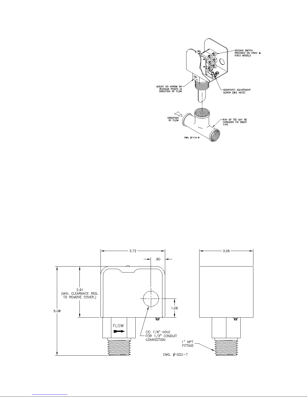
For a 1" pipe application mount in a standard 1" x
1" x 1" tee. Use a reducing tee for larger sizes of
pipe to keep flow switch close to pipe and provide
adequate paddle length in the flow stream.
Example: Use a 2" x 2" x 1" tee for 2" pipe. A
weldolet may also be used. Screw the device into
the tee fitting as shown in Fig. 4. The flat of the
paddle must be at a right angle to the flow. The
arrow on the side of the bushing must point in the
direction of flow, see Fig. 1.
FIG. 2
FIG. 1
Sensitivity Adjustment Note:
Turn screw clockwise to increase the flow rate
required to activate the switch.
Turn screw counter-clockwise to decrease the
flow rate required to activate the switch.
Page 3

FIG. 3
FIG. 5
Typical paddle arrangement
for 6" to 8" pipe, using smaller
flexible paddles for added
support and higher sensitivity.
Use the drawing at
right as a template
and trim at the dotted arc when trimming the appropriate paddle for intermediate pipe
sizes.
CAUTION:
The paddle must
not touch the inside of the pipe or
bind in any way.
NOTE:
When installing
rigid paddles, do
not stack paddles.
Only install ONE
paddle that best
fits the pipe.
FIG. 4
CAUTION:
Screw the device into the TEE fitting as shown.
Care must be taken to properly orient the device for
the direction of the flow. Do not tighten by grasping
the switch enclosure. Use the wrenching flats on the
bushing only. Turning radius required for mounting
the IFS is 3".
Page 4

WIRING
Use properly rated temperature supply wire for
the anticipated service temperature.
Make all electrical connections in accordance
with the National Electrical Code and local regulations.
See Figs. 6A and 6B for diagrams illustrating
switch action.
ADJUSTMENT
Remove switch cover and turn the sensitivity
adjusting screw clockwise to increase the flow
rate required to actuate the switch. Turn the
sensitivity adjusting screw counter-clockwise to
decrease the flow rate required to actuate the
switch. (See Fig. 1.) Be sure to replace the
cover upon completion of the installation and
adjustment.
CAUTION: Check the installation for "no-flow"
switch operation. Make appropriate adjustments
to the sensitivity adjustment screw to be sure the
switch restores fully at the desired flow rate.
FIG. 6A
FIG. 7
muminiM
tnemtsujdA
mumixaM
tnemtsujdA
IFS01 / IFS02
SWITCH INFORMATION
SNOITACIFICEPS
hctiwSetautcAotderiuqeRMPG-setaRwolFlacipyT
)snoitallatsniepiplacitrevroF(
)sehcni(eziSepiP14/112/1122/12345*68*
wolF
5.45.465.75.3181530507012
esaercnI
wolF
5.35.355.55.931520406091
esaerceD
wolF
5.9015.3102920507021081014
esaercnI
wolF
75.85.015.81625456501061083
esaerceD
IFSH1 / IFSH2
SWITCH INFORMATION
FIG. 6B
NOTES:
1. Typical flow rates for 1" to 1 1/2" pipe sizes
are averages which may vary approximately
±1 GPM with the use of a bronze reducing
tee.
2. Typical flow rates for 2" to 8" pipe sizes are
averages which may vary ±10% with the use
of a 1" weldolet.
(*) Flow rates for these sizes are calculated.
Do it Once. Do it Right.
TACO, INC., 1160 Cranston Street, Cranston, RI 02920 Telephone: (401) 942-8000 FAX: (401) 942-2360.
TACO (Canada), Ltd., 6180 Ordan Drive, Mississauga, Ontario L5T 2B3. Telephone: 905/564-9422. FAX: 905/564-9436.
Manufactured by POTTER ELECTRIC SIGNAL CO., St. Louis, MO
Visit our web site at: http://www.taco-hvac.com
Printed in USA
Copyright 2002
TACO, Inc.
 Loading...