

Page 1

OPERATOR INSTRUCTIONS
This tapping attachment can be used on all types of manually operated
The tap will return to a forward rotation as soon as it is with-drawn
FOR REVERSIBLE TAPPING ATTACHMENT MODEL: HR 3 & 4
machines with rotating non-reversing spindles.
INSTALLING MORSE TAPER ARBOR
Clean the matching taper. Then with a twisting motion, insert the arbor
into the attachment. Strike the tang end of the arbor with a plastic
hammer to lock it firmly. The hex nuts are provided to remove the
arbor.
MOUNTING THE ATTACHMENT TO THE MACHINE
Mount the STOP ARM on the attachment. A circlip is provided to hold
the STOP ARM in place. Now mount the attachment on the machine
spindle. Ensuring that the taper is free of oil and grease. Extend strong
stop bar from machine spindle of machine table to engage short STOP
ARM. DO NOT HOLD STOP ARM BY HAND. DO NOT
LENGHTEN STOP ARM, DO NOT HOLD JOB BY HAND. Clamp
the job securely as full power of the machine is transmitted in reverse.
INSERTING THE TAP
A. MODEL : HR :
Insert the desire tap into the chuck of the attachment. The square
of the tap is fit and centered between adjustable square nuts &
further tighten Chuck Nut which forces the Collect to hold the tap
shank with a firm grip. Slacken adjustable square nut in order to
center the tap. Check that the adjustable square Nuts only grip the
square portion of the tap. Then firmly tighten the Adjustable
square nuts.
B. MODEL : HRF :
The Spindle of the attachment has a quick change device. Press
the bush of the adaptor (Model: QA) and insert the tap. Now
insert the adaptor with the tap into the spindle of the attachment.
To disengage the adaptor, push the bush of the adaptor again.
For each tap with varying shank dimension a different adaptor is
required.
TORQUE SETTING:
The torque adjustments are made by tightening or loosening the cup
nut (3) at the upper end of the attachment. When the desired torque
has been determined, the cup nut may be locked in place by a grub
screw (5). Proper procedure when beginning tapping operation in to
loosen the cup nut so that all the graduations on the body are visible.
Then tighten the cup nut progressively until the attachment will drive
a sharp tap. When the proper torque is determined for a specific job.
This reference point may be noted to save set up time in future. If later
during the operation the clutch slips it is evident that the tap is dull and
should be immediately exchanged for a sharp tap but the clutch should
not be tightened further.
THROUGH HOLE TAPPING:
Press the tap lightly against the mouth of the hole. The free axial float
is provided in the attachment which will automatically permit the tap
to follow its own lead. The operator merely moves the machine’s
spindle behind the lead of the tap until the desired, depth is reached.
To reduce the wear of the attachment it is recommended that a short,
quick upward movement of the machine spindle be made during
transition fro forward to reverse.
from the hole.
BOTTOM HOLE TAPPING
For accurate and efficient bottom hole tapping a machine feed stop
should be used to allow the attachment’s spindle to disengage in
neutral before the tap bottoms in the hole. To achieve this, set the
machine stop so that machine feed plus the attachment’s self feed
will equal the desired thread depth.
If clutch should slip before the tap reaches the desired depth,
check to see that the hole is of the correct size not packed with
chips, and that the tap is sharp and undamaged. The torque
control clutch is designed as a safety device to prevent tap
breakage in ease the tap accidentally hits to the bottom. We do
not recommend using the clutch for repetitive hole tapping unless
absolutely necessary.
TAPPING SPEED
The factors to be considered when trying to determine the best
tapping speed are :
* Material to be tapped.
* Pitch of the thread.
* Selection of tap :
● Length of chamfer on tap
● Rake Angle
● Standard, spiral or spiral point
* The percentage of full thread to be cut.
The tapping speed must be reduced as the Percentage
of full thread to be cut is increased.
* Drilled hole with respect to length of the hole to be tapped.
* Cutting fluid
* Straight or tapered thread to be tapped.
This tapping attachments have been designed to operate at max
800 R.P.M.
CUTTING FLUID :
The cutting fluid works two ways. Heat generated as the tap
proceeds into the hole both by the deformation of the material and
by friction. The fluid must discipate this heat. The fluid must also
lubricate so that the friction between the tap, the chips and the hold
is minimized.
Be sure to use large quantities of cutting fluid under pressure for
tapping. The higher the cutting speed, the deeper the hole and the
tougher the material, the more cutting fluid you will need.
LUBRICATION :
This attachment is prepacked at the factory and only needs periodic additions of grease to maintain proper lubrication. Approximately
every 600 Hrs partially disassemble the attachment and clean ball
bearing and gears. Add a small amount of grease and reassemble. Do
not over lubricate. Excess grease will create internal friction and overheating.
SERVICE OVERHAUL AND REPAIR
Since overhaul and repair are time consuming for someone not
familiar with the attachment, we recommend that they be sent to us.
We will be glad to get your tapping attachment operational again in
shortest possible time.
Page 2
HR 4
Page 3

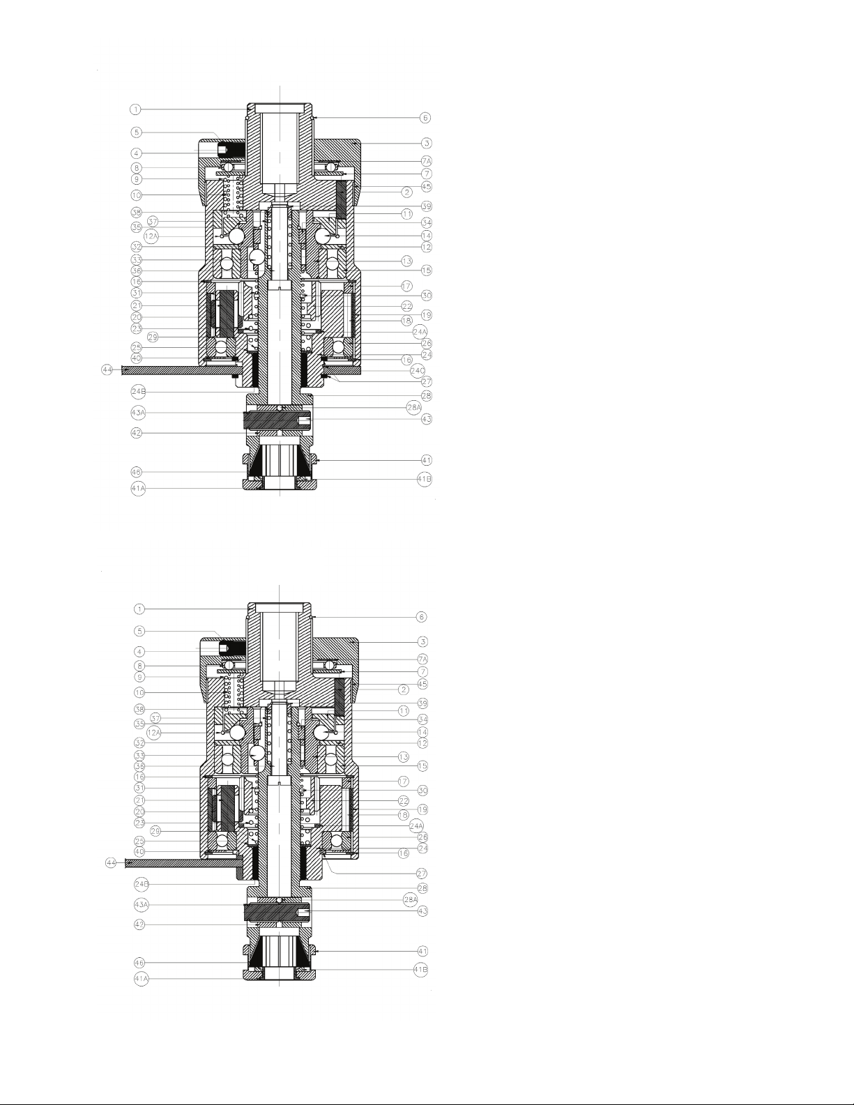
NOMENCLATURES
Ordering Numbers
Part No.
Part Name
HR3
HRF3
HR4
HRF4
1.
Body
1 HR3 (a)
1 HR3 (a)
1HR4(a)
1HR4(a)
2.
Pin for Body
2 HR3 (a)
2 HR3 (a)
2HR4(a)
2HR4(a)
3.
Cup Nut
3 HR3
3 HR3
3HR4
3HR4
4.
Pin for Cup Nut
4 HR3
4 HR3
4HR4
4HR4
5.
Grub Screw
5 HR3
5 HR3
5HR4
5HR4
6.
Lockring for Cup Nut
6 HR3
6 HR3
6HR4
6HR4
7.
Washer for Cup Nut
7 HR3
7 HR3
7HR4
7HR4
7A.
Washer for Cup Nut
7 AHR3
7 AHR3
7AHR4
7AHR4
8.
Thrust Bearing
8 HR3
8 HR3
8HR4
8HR4
9.
Pressure Spring Outer
9 HR3 (9 Nos.)
9 HR3 (9 Nos.)
9HR4(6Nos)
9HR4(6Nos)
10.
Pressure Spring Inner
10 HR3 (9 Nos.)
10 HR3 (9 Nos.)
10HR4(6Nos)
10HR4(6Nos)
11.
Pressure Plate
11 HR3
11 HR3
11HR4
11HR4
12.
Clutch Driver
12 HR3
12 HR3
12HR4
12HR4
12.A
Lockring for Clutch Driver
12 AHR3
12 AHR3
12AHR4
12AHR4
13.
Forward Driver
13 HR3©
13 HR3©
13HR4©
13HR4©
14.
Balls for Forward Driver
14 HR3(6Nos)
14 HR3(6Nos)
14HR4(6Nos)
14HR4(6Nos)
Ball Bearing for Forward
16.
Circlip for Body
16 HR3(2Nos)
16 HR3(2Nos)
16HR4(2Nos)
16HR4(2Nos)
17.
Spacer
17 HR3
17 HR3
17HR4
17HR4
18.
Gear Ring
18 HR3
18 HR3
18HR4
18HR4
19.
Key for Gear Ring
19 HR3
19 HR3
19HR4
19HR4
20 HR3 (b) 3
Nos.
21.
Pin for Pinion
21 HR3 (b) 3 Nos.
21 HR3 (b) 3 Nos.
21HR4(b)3Nos
21HR4(b)3Nos
22.
Reverse Gear
22 HR3
22 HR3
22HR4
22HR4
23.
Spring for Reverse Gear
23 HR3
23 HR3
23HR4
23HR4
24.
Carrier
24 HR3 (b)
24 HR3 (b)
24HR4(b)
24HR4(b)
24 A
Ring for Carrier
24 AHR3 (b)
24 AHR3 (b)
24AHR4(b)
24AHR4(b)
24 B
Bush for Carrier
24 BHR3 (b)
24 BHR3 (b)
24BHR4(b)
24BHR4(b)
24 C
Spacer for Carrier
24 CHR3 (b)
24CHR3 (b)
-
-
25.
Washer for Carrier
25 HR3 (b)
25 HR3 (b)
25HR4 (b)
25HR4 (b)
26.
Ball Bearing for Carrier
26 HR3 (b)
26 HR3(b)
26HR4 (b)
26HR4 (b)
27.
Circlip for Carrier
27 HR3 (2 Nos.)
27 HR3 (2 Nos.)
27HR4
27HR4
28.
Spindle
28 HR3
-
28HR4
-
28.A
Pin for Spindle
28 AHR3
-
28AHR4
-
29.
Expansion Spring
29 HR3
29 HR3
29HR4
29HR4
30.
Lockring for Spindle
30 HR3
30 HR3
30HR4
30HR4
31.
Spring for Ball Carrier
31 HR3
31 HR3
31HR4
31HR4
32.
Ball Carrier
32 HR3
32 HR3
32HR4
32HR4
33.
Balls for Ball Carrier
33 HR3 (3Nos)
33 HR3(3Nos)
33HR4(3Nos)
33HR4(3Nos)
34.
Washer for Spindle
34 HR3
34 HR3
34HR4
34HR4
35.
Lockring for Washer
35 HR3
35 HR3
35HR4
35HR4
36.
Stud for Spindle
36 HR3
36 HR3
36HR4
36HR4
37.
Comp. Spring for Stud
37 HR3
37 HR3
37HR4
37HR4
38.
Washer for Stud
38 HR3
38 HR3
38HR4
38HR4
39.
Lockring for Stud
39 HR3
39 HR3
39HR4
39HR4
40.
Thrust Washer
40 HR3
40 HR3
40HR4
40HR4
41.
Chuck Nut
41HR3(d)
-
41HR4(d)
-
41A.
Bush for Chuck Nut
41AHR3 (d)
-
41AHR4(d)
-
41B.
Washer for Chuck Nut
41BHR3 (d)
-
41BHR4(d)
-
42
L–R Nuts
42 HR3
-
42HR4
-
43.
L–R Stud
43 HR3
-
43HR4
-
43A.
E–Type Circlip
43AHR3
-
43AHR4
-
44.
Stop Arm
44 HR3
44 HR3
44HR4
44HR4
45.
Torque Strip
45 HR3(a)
45 HR3(a)
45HR4(a)
45HR4(a)
46.
Collet
S413
-
S613
-
Collet
S453
-
S623
-
47.
Spanner Set
47 HR3
-
47HR4
-
48.
Allen Key
48 HR3
48 HR3
48HR4
48HR4
49.
Arbor
(a)M20x2.50/MT2
49(a)HR3
49(a)HR3
-
-
(b) M20 x 2.50/MT3
49(b) HR3
49(b) HR3
49(b)HR4
49(b)HR4
(c) M20x2.50/MT4
49© HR3
49© HR3
49b©HR4
49©HR4
15.
20. Pinion 20 HR3 (b) 3 Nos.
Driver
15 HR3© 15 HR3© 15HR4© 15HR4©
20HR4(b)3Nos 20HR4(b)3Nos
Page 4

Cutting Speed
Type Tap. - HSS
Steel carbon
0.50 – 1.10 %C
20 – 40
Or Sulphur-base oil
Steel-Chromium Nickel
10˚ - 15˚
10 – 30
Heavy Sulphur-base oil
Steel-Chromium-
Heavy Chloride base oil
Sulphur-base oil
Monel Metal
10˚ - 15˚
10 – 23
Heavy Chloride base oil
Soluble oil or Sulphur-
Iron-cast
3˚ - 7˚
30 – 80
Dry or Soluble oil
Soluble oil or light base
oil
Soluble oil or light base
oil
Bronze
5˚ - 10˚
35 – 60
Dry
Aluminum Drawn
20˚ – 30˚
60 – 100
Kerosene or Soluble oil
Aluminum Cast
10˚ – 15˚
60 – 100
Kerosene or Soluble oil
Duralumin
10˚ – 20˚
60 – 100
Dry
Bakelite
0˚ – 5˚
30 – 65
Dry
Plastics, Soft
20˚ - 30˚
60 – 70
Dry
The above information are subject to Tapping Speed instructions
(d) M20x2.50/MT5
-
-
49(d)HR4
49(d)HR4
(e) JT3/MT3
49(e) HR3
49(e) HR3
-
-
(f) JT3/MT4
49(f) HR3
49(f) HR3
-
-
(g) JT4/MT4
-
-
49(g)HR4
49(g)HR4
(h) JT4/MT5
-
-
49(h)HR4
49(h)HR4
50
Nut for Arbor
50HR3
50HR3
50HR4
50HR4
51.
Spindle
--
51 HRF3
-
51HRF4
52.
Pressure Block
--
52 HRF3
-
52HRF4
53.
Spring for Pressure Block
--
53 HRF3
-
53HRF4
54.
Lockring for Pressure Block
--
54 HRF3
-
54HRF4
55. Balls -- 55HRF3(3Nos) - 55HRF4(3Nos)
56. Knurling Sleeve -- 56 HRF3 - 56HRF4
57. Spring for Kn. Sleeve -- 57 HRF3 - 57HRF4
58. Lockring for Kn. Sleeve -- 58 HRF3 - 58HRF4
Note: - Following parts are only available as an assembly.
(a) Body (1) with Part No. (2) and (45).
(b) Carrier (24) with Part No. (20), (21), (24A), (24B), (24C), (25) and bearing (26).
(c) Bearing (15) with Part No. (13).
(d) Chuck Nut (41) with Part No. (41A) and (41B).
Recommended Cutting Speed
Material Rake Angle
0.10 – 0.50 % C
Molybdenum
10˚ - 15˚
10˚ - 15˚ 10 – 30 Heavy Sulphur-base oil
Speed feet/min
20 – 50
Steel-stainless 10˚ - 15˚ 10 – 23
Steel-cast 10˚ - 15˚ 15 – 50
Brass Drawn 10˚ - 15˚ 60 – 100
Brass Cast 0˚ - 5˚ 60 – 100
Cutting Fluid
Oil emulsion
base oil
Page 5
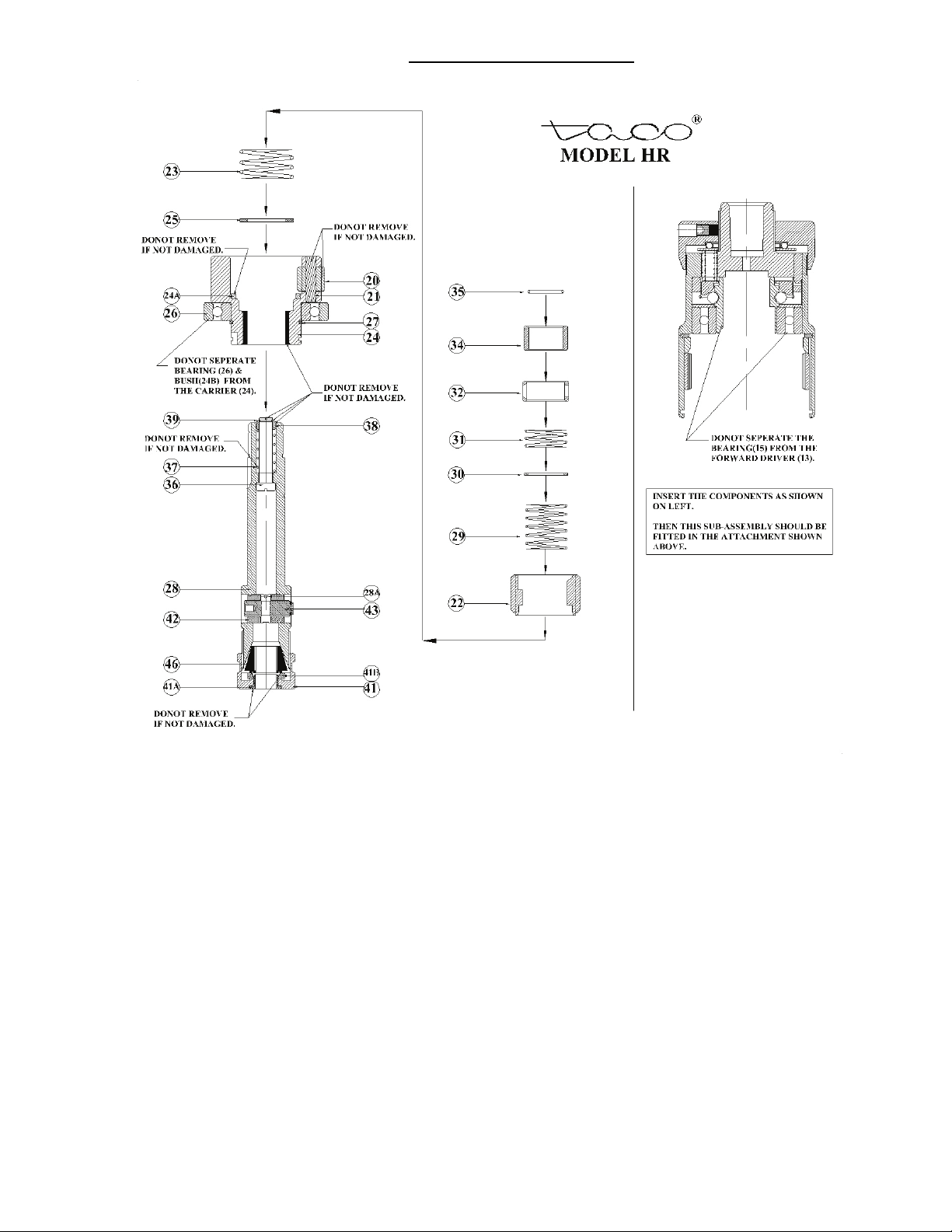
ASSEMBLY PROCEDURE
INSTRUCTIONS FOR DISASSEMBLY
1. Remove Lockring (6) and unscrew cup nut (3).
2. Hold unit in vertical position and remove thrust bearing (8), Washer (7) & Washer (7A).
3. Carefully invert unit over a clean receptable, pressure springs (9 & 10) will drop out.
4. From the lower end remove Chuck Nut (41),Collet (46) if necessary then remove E-Type Circlip (43A) and Loosen L-R stud (43) to remove Nuts(42)
(For Model HR).
5. Remove Circlip (27), Stop Arm (44), Circlip (16) and Bearing Cover (40).Do not remove Circlip (27) which holds bearing.
6. Lift out complete gear – carrier sub-assembly with spindle unit.
7. Remove Gear Ring (18), key (19) and Spacer (17).
8. Remove Lockring (35), Washer (34), Ball Carrier (32), Balls (33) and Spring (31).
9. Lift out Reverse Gear (22) and Spring (23).
10. Remove Lockring (30), Expansion Spring (29) and Washer (25) for relieving spindle unit from Carrier sub-assembly.
11. Remove Circlip (16) for disassembling clutch sub-assembly. Invert the Body over a clean receptable. Lift off pressure plate (11), Balls (14),
Clutch Driver (12). For reassembly pack grease in clutch sub-assembly, so Pressure Plate (11) will stay in place while reassembling Clutch
Bearing assembly.
12. Do not disassemble Ball bearings (15 & 26).
13. Do not disassemble pinion (20) – Carrier (24) sub assembly.
INSRTUCTIONS FOR ASSEMBLY
1. Clean and lubricate all parts requiring lubrication thoroughly.
2. Reverse procedure for assembly.
Page 6
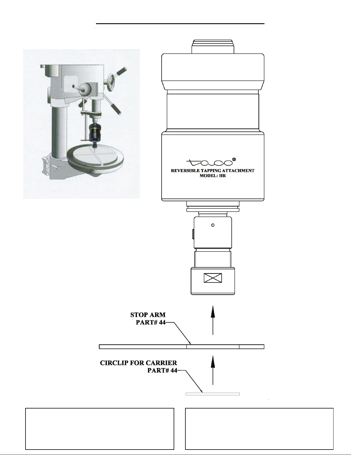
PROCEDURE FOR MOUNTING THE STOP-ARM
 Loading...