

Page 1

102-477
Installation & Operating Instructions
FloodBreaker®
SUPERSEDES: December 18, 2013 EFFECTIVE: December 10, 2014
Plant ID No. 001-4063
Page 2

2
Page 3

Table of Contents
Page
Safety information . . . . . . . . . . . . . . . . . . . . . . . . . . . . . . . . . . . . . . . . . . . . . . . . . . . . . . . . . . . . . . . . . . . . . 4
1. Application . . . . . . . . . . . . . . . . . . . . . . . . . . . . . . . . . . . . . . . . . . . . . . . . . . . . . . . . . . . . . . . . . . . . . . . . . . . 4
2. Factory Default Settings . . . . . . . . . . . . . . . . . . . . . . . . . . . . . . . . . . . . . . . . . . . . . . . . . . . . . . . . . . . . . . . . 4
3. Inserting / Changing Batteries . . . . . . . . . . . . . . . . . . . . . . . . . . . . . . . . . . . . . . . . . . . . . . . . . . . . . . . . . . . 5
4. General Operation . . . . . . . . . . . . . . . . . . . . . . . . . . . . . . . . . . . . . . . . . . . . . . . . . . . . . . . . . . . . . . . . . . . . . 5
4.1 Unlocking the keyboard . . . . . . . . . . . . . . . . . . . . . . . . . . . . . . . . . . . . . . . . . . . . . . . . . . . . . . . . . . . . . . . . 5
5. User Menu . . . . . . . . . . . . . . . . . . . . . . . . . . . . . . . . . . . . . . . . . . . . . . . . . . . . . . . . . . . . . . . . . . . . . . . . . . . 6
5.1 Standard leak protection . . . . . . . . . . . . . . . . . . . . . . . . . . . . . . . . . . . . . . . . . . . . . . . . . . . . . . . . . . . . . . . 6
5.2 Setting the standard leakage protection . . . . . . . . . . . . . . . . . . . . . . . . . . . . . . . . . . . . . . . . . . . . . . . . . . 6
5.3 Temporarily deactivating the leakage protection . . . . . . . . . . . . . . . . . . . . . . . . . . . . . . . . . . . . . . . . . . . 7
5.4 Vacation leakage protection . . . . . . . . . . . . . . . . . . . . . . . . . . . . . . . . . . . . . . . . . . . . . . . . . . . . . . . . . . . . 7
5.5 Setting the vacation leakage protection . . . . . . . . . . . . . . . . . . . . . . . . . . . . . . . . . . . . . . . . . . . . . . . . . . . 7
5.6 Deactivating the vacation leakage protection . . . . . . . . . . . . . . . . . . . . . . . . . . . . . . . . . . . . . . . . . . . . . . 8
5.7 Re-opening after a leak shut-off . . . . . . . . . . . . . . . . . . . . . . . . . . . . . . . . . . . . . . . . . . . . . . . . . . . . . . . . . 8
5.8 Opening and closing the FloodBreaker . . . . . . . . . . . . . . . . . . . . . . . . . . . . . . . . . . . . . . . . . . . . . . . . . . . 8
6. Advanced Menu Settings . . . . . . . . . . . . . . . . . . . . . . . . . . . . . . . . . . . . . . . . . . . . . . . . . . . . . . . . . . . . . . . 8
6.1 48 hour leak monitor . . . . . . . . . . . . . . . . . . . . . . . . . . . . . . . . . . . . . . . . . . . . . . . . . . . . . . . . . . . . . . . . . . . 9
6.2 Activating / deactivating the 48 hour leak monitor . . . . . . . . . . . . . . . . . . . . . . . . . . . . . . . . . . . . . . . . . . 9
6.3 Time-based leak protection (Time . . . . . . . . . . . . . . . . . . . . . . . . . . . . . . . . . . . . . . . . . . . . . . . . . . . . . . . 9
6.4 Time-based leakage (flow rate) . . . . . . . . . . . . . . . . . . . . . . . . . . . . . . . . . . . . . . . . . . . . . . . . . . . . . . . . . . 9
6.5 Volume base leak (secondary check) . . . . . . . . . . . . . . . . . . . . . . . . . . . . . . . . . . . . . . . . . . . . . . . . . . . . 10
6.6 Output contact . . . . . . . . . . . . . . . . . . . . . . . . . . . . . . . . . . . . . . . . . . . . . . . . . . . . . . . . . . . . . . . . . . . . . . 10
6.7 Internal alarm . . . . . . . . . . . . . . . . . . . . . . . . . . . . . . . . . . . . . . . . . . . . . . . . . . . . . . . . . . . . . . . . . . . . . . . 11
6.8 IN1 floor sensor . . . . . . . . . . . . . . . . . . . . . . . . . . . . . . . . . . . . . . . . . . . . . . . . . . . . . . . . . . . . . . . . . . . . . . 11
6.9 IN2 input contact . . . . . . . . . . . . . . . . . . . . . . . . . . . . . . . . . . . . . . . . . . . . . . . . . . . . . . . . . . . . . . . . . . . . . 12
6.10 Full or partial monitoring . . . . . . . . . . . . . . . . . . . . . . . . . . . . . . . . . . . . . . . . . . . . . . . . . . . . . . . . . . . . . . 12
7. System Information Menu . . . . . . . . . . . . . . . . . . . . . . . . . . . . . . . . . . . . . . . . . . . . . . . . . . . . . . . . . . . . . 12
7.1 Software version . . . . . . . . . . . . . . . . . . . . . . . . . . . . . . . . . . . . . . . . . . . . . . . . . . . . . . . . . . . . . . . . . . . . . 13
7.2 Battery power . . . . . . . . . . . . . . . . . . . . . . . . . . . . . . . . . . . . . . . . . . . . . . . . . . . . . . . . . . . . . . . . . . . . . . . 13
7.3 Alarm memory . . . . . . . . . . . . . . . . . . . . . . . . . . . . . . . . . . . . . . . . . . . . . . . . . . . . . . . . . . . . . . . . . . . . . . . 13
8. Using the Manual Key . . . . . . . . . . . . . . . . . . . . . . . . . . . . . . . . . . . . . . . . . . . . . . . . . . . . . . . . . . . . . . . . . 13
8.1 Installing the control unit back onto the valve body . . . . . . . . . . . . . . . . . . . . . . . . . . . . . . . . . . . . . . . . 14
9. Specifications . . . . . . . . . . . . . . . . . . . . . . . . . . . . . . . . . . . . . . . . . . . . . . . . . . . . . . . . . . . . . . . . . . . . . . . 14
10. Connections . . . . . . . . . . . . . . . . . . . . . . . . . . . . . . . . . . . . . . . . . . . . . . . . . . . . . . . . . . . . . . . . . . . . . . . . . 14
11. Dimensions . . . . . . . . . . . . . . . . . . . . . . . . . . . . . . . . . . . . . . . . . . . . . . . . . . . . . . . . . . . . . . . . . . . . . . . . . 15
12. Messages . . . . . . . . . . . . . . . . . . . . . . . . . . . . . . . . . . . . . . . . . . . . . . . . . . . . . . . . . . . . . . . . . . . . . . . . . . . 15
13. Installing the FloodBreaker . . . . . . . . . . . . . . . . . . . . . . . . . . . . . . . . . . . . . . . . . . . . . . . . . . . . . . . . . . . . 16
3
Page 4
Safety Requirements
Consult local plumbing, building and electrical codes in
your area before installing the FloodBreaker®.
The FloodBreaker is for indoor use only and should
only be installed by qualified professionals. These
instructions are not intended to contradict any local building
codes. These instructions should be considered in addition to
local codes. Consult your local authority regarding any
instructions contradictory to code requirements.
1. Application
The Taco FloodBreaker® is a whole home adjustable leak
protection system that monitors several aspects of water
usage. It shuts off the water supply once any of the monitored settings are reached.
Note: The FloodBreaker will not be suitable for installa-
tions where the flow rate will exceed 15.5 GPM for 30 min-
utes or longer.
Warning: The FloodBreaker must not be installed
between the water source and a fire sprinkler system.
Failure to follow these instructions could result in serious per-
sonal injury, death and/or property damage.
Warning: Boilers must be equipped with both a boiler
relief valve and a low water cut-off before installing the
FloodBreaker. Failure to follow these instructions could result
in serious personal injury, death and/or property damage.
Warning: Water heaters must be equipped with a T & P
relief valve. Failure to follow these instructions could
result in serious personal injury, death and/or property damage.
Caution: FloodBreaker will not provide any protection
against water usage or leaks that take place prior to its
location in the piping system.
2. Factory Default Settings
DESCRIPTION
Standard Leak Protection LE 4
Vacation Leak Protection UL 10
Valve Position Ab P1
48 Hour Monitor 4# –
Time-Based (Volume) t1 –
Time-Based (Flow Rate) t2 1
Volume-Based Secondary Check E# –
Output Contact O# 1
Internal Alarm bu 1
Floor Sensor (In1) 11 1
External Contact (In2) 12 –
Monitoring Option H# c
MENU
DISPLAY
DEFAULT
SETTINGS
4
Page 5
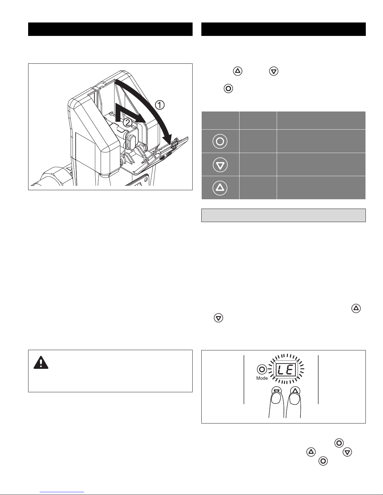
3. Inserting/Changing Batteries 4. General Operation
Insert the batteries prior to using the FloodBreaker. Open
the battery door and remove the battery block.
Figure 1
Insert new batteries or change used ones. Put the battery
block back into place in the battery compartment.
Make sure that the battery block is correctly positioned in
the compartment against the internal back wall or you may
experience difficulty closing the battery door. See Figure 1.
Close the battery door.
The FloodBreaker is supplied with an optional power cord so
that you can also connect the FloodBreaker to an external
power source.
Note: Not all operations function on battery power alone,
some will require the use of the external power source.
The control consists of a two digit display and three push
buttons (mode, up and a down button).
Use the up or down button to adjust the values.
Use the to confirm and save the values or to scroll through
the menu items.
Symbol Key Function
Mode Scroll / Save Settings
Down To decrease values
Up To increae values
4.1 Unlocking the keyboard
When the FloodBreaker is exclusively battery operated,
press any button to activate the display. It will sleep automatically after approximately 30 seconds of no use.
The menu is locked automatically.
The menu must be unlocked to scroll through menus or
change any values.
In order to unlock the menu, simultaneously press the
and buttons for about 3 seconds. There will be a short
beep and the display starts flashing to signal that the menu
is unlocked. (See Figure 3)
Warning: The batteries must be inserted even when
using the power cord. Replace the batteries annually!
Never mix old and new batteries. Always install 4 new AA
alkaline batteries!
Figure 3
Scroll through the menu by pressing the Mode button.
Change the values by pushing the up or down buttons. Save changes by pressing the mode button.
5
Page 6

Once cycled through all three primary menus the keyboard
returns to the locked position. If no button is pushed for 30
seconds the display goes blank and returns to the locked
position.
Note: If the FloodBreaker is attached to an external
power source, the display always remains active.
5.2 Setting the standard leak
protection
If you are not using an external power source, press any
button to activate the display. LE appears in the display
window. If vacation leak mode is activated UL appears in
the display instead.
5. User Menu
5.1 Standard leak protection
In the standard leak protection mode the system monitors the
water volume used without any interruption, the length of time
water is used without interruption as well as the flow rate.
Should one of the following criteria be exceeded, the device
suspects a leak, closes the valve and displays a shut-off
code.
1. Volume-based leak – Message A3 is displayed if the
water volume used exceeds the set limit without interruption.
2. Flow rate – Message A4 is displayed if 15.5 GPM is
exceeded for the set period of time.
3. Time-based leak – Message A9 is displayed when constant flow is detected over a time limit based on the following settings. To override the default time see section
6.3.
Note: The FloodBreaker is shipped with the Vacation Leak
Protection (UL) setting active. Vacation Leak Protection
will override the Standard Leak Protection (LE) and must
be deactivated (See section 5.5) for the Standard Leak
Protection to be active.
1. Unlock the menu per previous instructions in section
4.1 (Figure 3); either LE or UL will be flashing on the display screen.
2. Press the button once and LE will be displayed
(Figure 4).
Figure 4
LE Standard Protection Setting Default Time
Leak setting 1-4 2 hours
Leak setting 5-7 3 hours
Leak setting 8-11 4 hours
Leak setting 12 - 15 5 hours
Note: The valve will close if constant flow is detected once
the time limit is reached. This happens even if the water
volume has not reached the leak set point.
6
3. Press the button again to display the current leak
setting (Figure 5).
Figure 5
Page 7

4. Using the and buttons adjust the FloodBreaker
to the desired setting. See Table 1 for code key.
Table 1
LE Standard
Protection Setting
–– Deactivated
1 25
2 55
3 80
4 105
5 130
6 160
7 185
8 210
9 240
10 265
11 290
12 315
13 345
14 370
15 395
Approximate
Gallons
5.4 Vacation leak protection
During periods when the house may be unoccupied a tighter leak
protection may be desired. This can be accomplished using the
vacation leak mode and does not require changing the normal
leak protection setting. When activated it overrides the standard
leak protection.
The vacation leak protection is adjustable from 3-26 gallons of
uninterrupted flow. If the vacation leak setting is exceeded a leak
is suspected, the FloodBreaker closes thus shutting off the water
and the Message A5 is displayed.
5.5 Setting the vacation leak
protection
1. Unlock the Keyboard. Press the button until reach-
ing the UL menu (Figure 7).
Once the LE number is selected press the button to enter
and save the changes.
Note: Anytime a program change is made press the
button after the change to enter and save the change.
5.3 Temporarily deactivating the
standard leak protection
To temporarily deactivate the standard leakage protection, follow
the instructions in 5.2 and select the -- leak setting shown in
Figure 6. After saving and returning to the home screen, “0” will
be displayed during the deactivation period.
Figure 7
2. Press the button once more to reach the adjusting
screen. Set the desired value by using the and
buttons (Figure 8). See Table 2 for the code Key.
Figure 8
3. Press the button again to save.
Figure 6
Note: The standard leak protection mode is automatically
reactivated after 8 hours.
7
Page 8

Table 2
(UL) Vacation Leak
Settings
–– Deactivated
1 3
2 5
3 8
4 11
5 13
6 16
7 18
8 21
9 24
10 26
Approximate
Gallons
5.8 Opening and closing the
FloodBreaker
1. Unlock the keyboard. Press the button until reach-
ing the manual menu identified as Ab (Figure 11).
Figure 11
Note: When vacation leak protection mode is activated, it
overrides any standard leak protection.
5.6 Deactivating vacation leak
protection
In order to turn off the vacation leak mode follow instructions in 5.5 and set vacation leak to - - (Figure 9).
Figure 9
2. Press the button again to view the current position.
3. Use the or button to change the FloodBreaker‘s
current position. P1 is the open position and P2 is the
closed position (Figure 12).
Figure 12
4. Once the desired position is displayed press the
button to activate and save the setting.
5.7 Re-opening after a leak shut-off
When the FloodBreaker has detected a leak and isolated
the system it can be re-opened by pressing the button
(Figure 10).
Figure 10
8
6. Advanced Menu Settings
In order to view the advanced menu, press and hold the
button. While holding the mode button, press the button three times and then release both buttons. You may now
scroll through the advanced menu.
If you wish to make adjustments to any settings in the
advanced menu, it must be unlocked per the user menu
instructions in section 4.1.
Note: Changes should only be made to Advanced Menu
Setting after reading and understanding these functions.
Page 9

6.1 48 hour leak monitor
6.3 Time-based leak protection (Time)
The 48 hour monitor is an additional method to check for
leaks. This function can be used when you may be away from
home for longer than several hours and have not activated
the vacation leak protection. When this monitor is activated
and no water is drawn off for 48 hours, the FloodBreaker
closes to isolate the system for 3 minutes.
After three minutes the device opens again and verifies
whether there is a flow of water. If it detects a flow of 81⁄2
ounces, a leak is suspected and the device will close.
Message A8 is displayed.
The 48 hour leak monitor is factory shipped in the off
mode.
6.2 Activating and deactivating
the 48 hour leak monitor
Enter and unlock the Advance Menu Settings. 4- is shown
and the (-) will be blinking, indicating that the setting can be
changed and the monitor is in the deactivated position
(Figure 13).
The time-based protection is factory set to the off position.
When the time-based leak protection is activated, the
default time setting used in conjunction with the standard
leak setting is replaced by this new setting. (See section 5.1
for default time settings).
Example: With a Standard Leak Protection setting of 1-4
the default time would be 2 hours. If the time-based leak
protection is activated and set to 8 hours, the new time setting for any Standard Leak Protection is 8 hours. This
would mean that the FloodBreaker would not suspect a
leak until either the set volume of water is reached or a flow
of water is detected for 8 continuous hours.
Press the button until the display shows t1 (Figure 14).
Figure 14
Figure 13
Set the monitor to the active position by pressing the or
button so the number (8) is displayed instead of the -.
To save the settings press the button.
Press the button again and use the or buttons
to adjust the number of hours that continuous flow is
acceptable before the unit closes. Save any changes by
pressing the button.
6.4 Time-based leak protection (High
Flow Rate)
The FloodBreaker will not be suitable for installations that
will exceed 15.5 GPM for 30 minutes or longer.
The factory setting is 1 minute. If the flow rate exceeds 15.5
GPM for 1 minute a leak is suspected, the valve will close
and message A4 is displayed.
The maximum flow rate is not adjustable. The time limit can
be adjusted between 1 to 30 minutes. It cannot be turned
off.
9
Page 10

Press the button until the time-based flow rate menu is
displayed as t2 (Figure 15).
Figure 15
Figure 17
Press the button to save the change.
Press the button again and use the or buttons
to set how many minutes the FloodBreaker waits before
shutting off the water supply when the flow exceeds 15.5
GPM (Figure 16).
Figure 16
Save the change by pressing the button again.
6.5 Volume-based leak secondary
check
This feature allows the FloodBreaker to double check for a
leak when a volume-based leak is detected. The factory
setting is deactivated or off (E-).
When the recheck feature is activated (E1) and the
FloodBreaker detects a leak, it shuts off the water. It will reopen after 30 seconds to see if water is actually being
drawn off. If water flow is detected the valve will close and
not open again until it is reset. If no water flow is detected
the valve will remain open and allow water usage up to the
set points.
6.6 Output contact
This is a dry contact with a 24Volt/2amp maximum switching capability.
The primary use for this contact would be an external alarm
display or signal. The factory setting is o1.
Setting Meaning Symbol
Contact is
deactivated
Closing contact
Opening contact
Momentary
Figure 18
Press the button until the current setting is shown. Use
the or button to set the contact to the required function (Figure 18). Save any changes by pressing the button again.
Note: The external power supply must be used for the out-
put contact to function. It will not function on battery
power alone.
Press the up or down button to activate (E1) or deactivate (E-) (Figure 17).
10
Page 11

6.7 Internal alarm 6.8 In1 – Floor sensor
The FloodBreaker has an audible alarm that will sound
when a leak is detected and the valve closes.
Press the until bu is shown (Figure 19).
Figure 19
Press the button again to make adjustments. Use the
up or down button to activate (1) or deactivate (-)
(Figure 20). Press the button to save the change.
Press the until 11 is shown (Figure 21).
Figure 21
Press the button again to make adjustments. Use the
up or down button to activate (1) or deactivate (-)
(Figure 22).
Figure 20
Note: The external power supply must be used for the
internal alarm to function. It will not function on battery
power alone.
Figure 22
Note: When using the floor sensor, make sure it is fully
inserted into the socket or it will not function properly.
When the sensor detects a leak and closes the valve, A6 is
displayed. It will take approximately 1 minute for the floor
sensor to register a leak.
11
Page 12

6.9 In2 – Input contact
key
key
key
The In2 contact offers multiple input possibilities such as
instant floor sensors, temperature probes, timers, radiocontrolled floor sensors, switch buttons, etc. None of these
items are provided by Taco but are standalone contact
devices. The contact is factory set to deactivate (--).
Press the until 12 is shown.
Settings 1-3 actuate the valve with an input signal as
shown. A7 is displayed when activated. Reset the
FloodBreaker by pressing the mode button.
Settings 4-6 actuate the valve with the input signal shown.
12 is displayed when activated. The FloodBreaker can
either be reset with a second as signal shown or the mode
button can be pressed.
Note: The external power supply must be used for the In2
contact to function. It will not function on battery power
alone.
6.10 Full or partial monitoring
Figure 23
Press the button again to change the setting. Use the
up or down buttons to change the type of contact
(Figure 23).
The contact has 7 possible Settings (Figure 24).
Setting
Meaning
Detect Reset
Contact is
deactivated
Impulse
Opening
contact
Closing
contact
Impulse
The FloodBreaker can be set to either full (Hc) or partial
(Hd) monitoring. The factory setting is (Hc). (Hc) would be
the setting for normal usage of the FloodBreaker. (Hd)
might be used for a period of time where an exceptionally
high usage of water is taking place, for example adding
water to a pool, and you prefer not to change the standard
leak setting. Remember to reset the FloodBreaker back to
(Hc) once your task is completed.
Caution: When set to partial monitoring (Hd), only the floor
sensor is functional. All other monitoring functions are
deactivated!
7. System Information Menu
To enter this menu, press and hold the button and then
press the once and release the mode button.
Note: This is a view only menu and no adjustments can be
made.
Opening
contact
Closing
contact
Figure 24
12
Press the mode button repeatedly to scroll through this menu.
Page 13

7.1 Software version
Figure 25
Remove the two cover halves (Figure 27).
Press the mode button to display the software version
(Figure 25).
7.2 Battery power
Figure 26
Press the mode button to display the battery voltage remaining (Figure 26).
7.3 Alarm memory
Figure 27
The key is located on the inner side of the left cover
(Figure 28).
Figure 28
Remove the locking clamp from the control head so that it
can be lifted off. Lift off the control (Figure 29).
The FloodBreaker can save up to 8 alarm messages. Scroll
through the saved messages by repeatedly pressing the
mode button. If no messages have been saved, FF will be
displayed.
8. Using the Manual Key
The manual key is provided in the event that the
FloodBreaker has closed and no power is available to open
the valve.
Caution: Before beginning, disconnect the batteries and
unplug the external power source if used.
Figure 29
Insert the key by aligning the key slot with the shaft and turn
it in the direction shown by the arrows to open (Figure 30).
Water flow should be back to normal.
13
Page 14

Press the down button to change to “P1” and then press the
OUT Output Contact
IN2 Input Contact
Power
Input
IN1 Floor sensor
9V DC
mode button to save. Once the control unit has rotated to
the open position and stopped it can be installed on the
valve body.
Align the valve stem and locating pin with the mating stem
slot and locating notch on the control unit. Slide the control
unit onto the valve stem. You may need to gently wiggle the
control unit until it is fully seated. Place the locking clamp
back into the clamp slots once the control unit is fully seated.
9. Specifications
Max Service Temperature: 86°F (30°C)
Figure 30
Remove the key from the valve body and follow instructions
in section 8.1 to install the control unit back onto the valve
body.
8.1 Installing the control unit back
onto the valve body
Since the valve position has been changed manually, the
control unit position and the valve body position no longer
match. This mismatch needs to be corrected before putting
the control back onto the body.
Caution: Do not use the control unit to manually turn the
valve body.
Once power has been restored the control unit needs to be
adjusted to match the valves current position.
Ambient Temperature: 50-140°F (10-60°C)
Max Pressure: 230 PSI (16 bar)
Batteries: 4 x AA
Power Supply: 9V DC
Output Contact: 24V DC / 2A max
In2: 12 V DC / 2mA
For Indoor Use Only
10. Connections
Unlock the keyboard.
Press the mode button until reaching controls current position status which should be a “P2” with 2 flashing (Figure 31).
14
Figure 31
Page 15

11. Dimensions
G
E
F
A
B
C
D
DIMENSIONS
(for reference only)
A 41⁄4 (108)
B
C 41⁄8 (105)
D 3 (76)
E 123⁄32 (307)
F 655⁄64 (174)
G 447⁄64 (120)
Inches (mm)
15
⁄16 (24)
12. Message Codes
DISPLAY INDICATION POSSIBLE CAUSE POSSIBLE SOLUTIONS
A1 The valve cannot rotate.
A2 The turbine cannot rotate. • Turbine is blocked • Consult factory
A3
A4
A5
A6
A7
A8
A9
A volume-base leak
has been detected.
A continuous flow >15.5 GPM
has been detected.
The system has exceeded
the vacation leak setting.
The floor sensor has
detected a leak.
A signal has been received
at contact In2.
A leak has been detected by
the 48 hour leak monitor.
A time-based leak has
been detected.
• Mechanism blocked
• Motor failed
• Plumbing has a leak
• Setting is too low
• Plumbing has a leak
• t2 setting too low
• Actual flow exceeds 15.5 GPM for 30 minutes
• Plumbing has a leak
• Leak setting too low
• Plumbing has a leak • Fix leak
• Plumbing has a leak • Fix leak
• Plumbing has a leak • Fix leak
• Plumbing has a leak
• Time setting is too low
• Remove blockage
• Press the mode button to try again
• Fix leak
• Adjust setting. Push mode button to reset.
• Fix leak
• Adjust t2 setting
• Reduce flow rate or the time of excess flow
below 30 minutes
• Fix leak
• Adjust the setting
• Fix leak
• Adjust the setting
bA The batteries are low. • The batteries are low • Replace the batteries
15
Page 16

13. Installing the FloodBreaker
FLOW IN FLOW OUT
For the most complete protection, the FloodBreaker should
be installed on the home’s incoming water supply and as
close to where the supply enters as possible. (Check with
local authorities for any restrictions.) The FloodBreaker
uses a universal body assembly and can be installed into
either a vertical or horizontal pipe line as shown (Figure 32).
The FloodBreaker universal body may now be attached to
the tailpieces already installed in the piping as shown
(Figure 32).
Note: Remove the clear protective plastic covering
from the face of the universal body.
Flush the piping before attaching the FloodBreaker to the
body. (Figure 34).
Figure 34
Attach the FloodBreaker to the universal flange body using
the 2 O-rings and the 4 body bolts provided (Figure 35).
Figure 32
Install the union nuts and tailpieces onto the piping system
before attaching them to the FloodBreaker body. Be sure to
mount the body in the correct flow orientation. The triangle on
one end of the body indicates the direction of flow (Figure 33).
Figure 33
Figure 35
systems made easy
TACO, INC., 1160 Cranston Street, Cranston, RI 02920 Telephone: (401) 942-8000 FAX: (401) 942-2360.
TACO (Canada), Ltd., 8450 Lawson Road, Unit #3, Milton, Ontario L9T 0J8. Telephone: 905/564-9422. FAX: 905/564-9436.
Visit our web site at: http://www.taco-hvac.com
16
®
Printed in USA
Copyright 2013
TACO, Inc.
 Loading...