

Page 1
A1
A1
L
A
h
H
2.0"
(51 mm)
removal
space
1
2
3
4
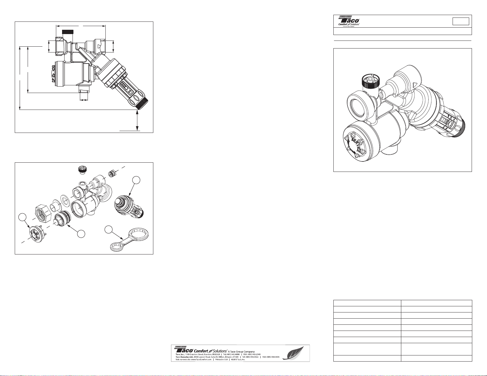
Dimensions:
A – 1⁄4" NPTF H – 4.5"
A1 – 1⁄2" NPTF h – 3.3"
L – 3.5"
Spare Parts Breakdown:
1 Backflow Cartridge Service Cap 3450-002RP
2 Backflow Preventor Cartridge 3450-001RP
3 Pressure Reducing Cartridge 3350-005RP
4 Wrench
Cartridge Replacement:
Note: When purchasing a replacement backflow or PRV
cartridge, Taco recommends also purchasing the wrench in
order to simplify removal and replacement of either part.
PRV – Close the isolation valves located on both sides of
the 3450 Combination Valve and open the drain at the
(not included with the valve purchase) 3450-003RP
upstream (inlet side) isolating valve. Loosen the cartridge
in the combination valve by placing the wrench (purchased separately) or other user provided tool over the 8
point cam nut and turn counterclockwise. Unscrew the
cartridge and remove it from the body. Install the new
cartridge hand tight. Fully tighten it using the cartridge
wrench or other tool. Do not over tighten. Close the previously opened drain, open the isolating valves and test per
local requirements.
Backflow – Close the isolation valves located on both sides
of the 3450 Combination Valve and open the drain at the
upstream (inlet side) isolating valve. The backflow cartridge
is located beneath the black service cap. In order to remove
the cap on the combination valve use the cap/cartridge
wrench (purchased separately) or other user provided tool.
Place the wrench over the 6 point star on the cap and turn
counterclockwise to loosen, remove the cap. A spring is
located behind the backflow cartridge that may push the cartridge out of the body when the cap is removed. Take care
not to lose the spring. If the cartridge remains in place with
the cap removed, pull it out. With the spring in place put the
new cartridge into the body. Using the 4 fingers on the service cap, push the cartridge into the body and turn the service cap clockwise until hand tight, fully tighten using the
wrench or other tool. Close the previously opened drain,
open the isolating valves and test per local requirements.
LIMITED WARRANTY STATEMENT
Taco, Inc. will repair or replace without charge (at the company’s option) any
product or part which is proven defective under normal use within one (1)
year from the date of start-up or one (1) year and six (6) months from date
of shipment (whichever occurs first).
In order to obtain service under this warranty, it is the responsibility of the
purchaser to promptly notify the local Taco stocking distributor or Taco in writing and promptly deliver the subject product or part, delivery prepaid, to the
stocking distributor. For assistance on warranty returns, the purchaser may
either contact the local Taco stocking distributor or Taco. If the subject product or part contains no defect as covered in this warranty, the purchaser will be
billed for parts and labor charges in effect at time of factory examination and
repair.
Any Taco product or part not installed or operated in conformity with Taco
instructions or which has been subject to misuse, misapplication, the addition of petroleum-based fluids or certain chemical additives to the systems,
or other abuse, will not be covered by this warranty.
If in doubt as to whether a particular substance is suitable for use with a Taco
product or part, or for any application restrictions, consult the applicable Taco
instruction sheets or contact Taco at [401-942-8000].
Taco reserves the right to provide replacement products and parts which are
substantially similar in design and functionally equivalent to the defective
product or part. Taco reserves the right to make changes in details of design,
construction, or arrangement of materials of its products without notification.
TACO OFFERS THIS WARRANTY IN LIEU OF ALL OTHER EXPRESS
WARRANTIES. ANY WARRANTY IMPLIED BY LAW INCLUDING WARRANTIES OF MERCHANTABILITY OR FITNESS IS IN EFFECT ONLY
FOR THE DURATION OF THE EXPRESS WARRANTY SET FORTH IN
THE FIRST PARAGRAPH ABOVE.
THE ABOVE WARRANTIES ARE IN LIEU OF ALL OTHER WARRANTIES,
EXPRESS OR STATUTORY, OR ANY OTHER WARRANTY OBLIGATION
ON THE PART OF TACO.
TACO WILL NOT BE LIABLE FOR ANY SPECIAL, INCIDENTAL, INDIRECT OR CONSEQUENTIAL DAMAGES RESULTING FROM THE USE
OF ITS PRODUCTS OR ANY INCIDENTAL COSTS OF REMOVING OR
REPLACING DEFECTIVE PRODUCTS.
This warranty gives the purchaser specific rights, and the purchaser may
have other rights which vary from state to state. Some states do not allow
limitations on how long an implied warranty lasts or on the exclusion of incidental or consequential damages, so these limitations or exclusions may not
apply to you.
Instructions for
Use and Installation
102-371
Backflow Preventer and Boiler Feed Valve (PRV)
SUPERSEDES: September 1, 2014 EFFECTIVE: September 1, 2015
Plant ID# 001-3942
Application:
Taco’s combination Backflow Preventer and Boiler Feed
Valve (PRV) is designed for use in today’s Hydronic heating
systems to protect against possible water contamination
from the heating system water flowing back into the
potable water supply. The combination valve is suitable
for systems with fill pressure requirements between
10-50 PSI. The Boiler Feed Valve (PRV) reduces incoming pressure and automatically maintains that system pressure to the valves adjustable pressure set point. The
Taco combination valve showcases a fast fill button with
automatic reset, this allows the valve to automatically
return to maintaining the adjusted pressure setting once
the system is full and the set pressure is reached. No
more manually holding the valve open or locking it in an
open position and over pressurizing to the point of setting
off the relief valve. The integral Backflow Preventer prevents the back flow of non potable heating system water
into the Potable water supply.
Technical Specifications:
Connections 1/2" x 1/2"
Maximum Inlet Pressure 150 psi
Minimum Delta P Inlet to Outlet 15 psi
Recommended Setting Range 10-50 psi +/-3 psi
Factory Setting 12 psi
Adjustment Capability 8.5 - 65 psi
Maximum Flow Rate(velocity) 25 gpm (8 ft / sec)
Mounting Position
Maximum Temperature 210°F
Horizontal Flow with Atmospheric
Vent toward the floor
Page 2
Installation:
1
3
4
2
TACO
3450
TACO
4900 SERIES
WATER
BOILER
TACO
CIRCULATOR
DIAPHRAGM TYPE
EXPANSION TANK
COLD
SUPPLY
DRAIN PIPE
(NOT PROVIDED
BY TACO)
DRAIN
4" MIN
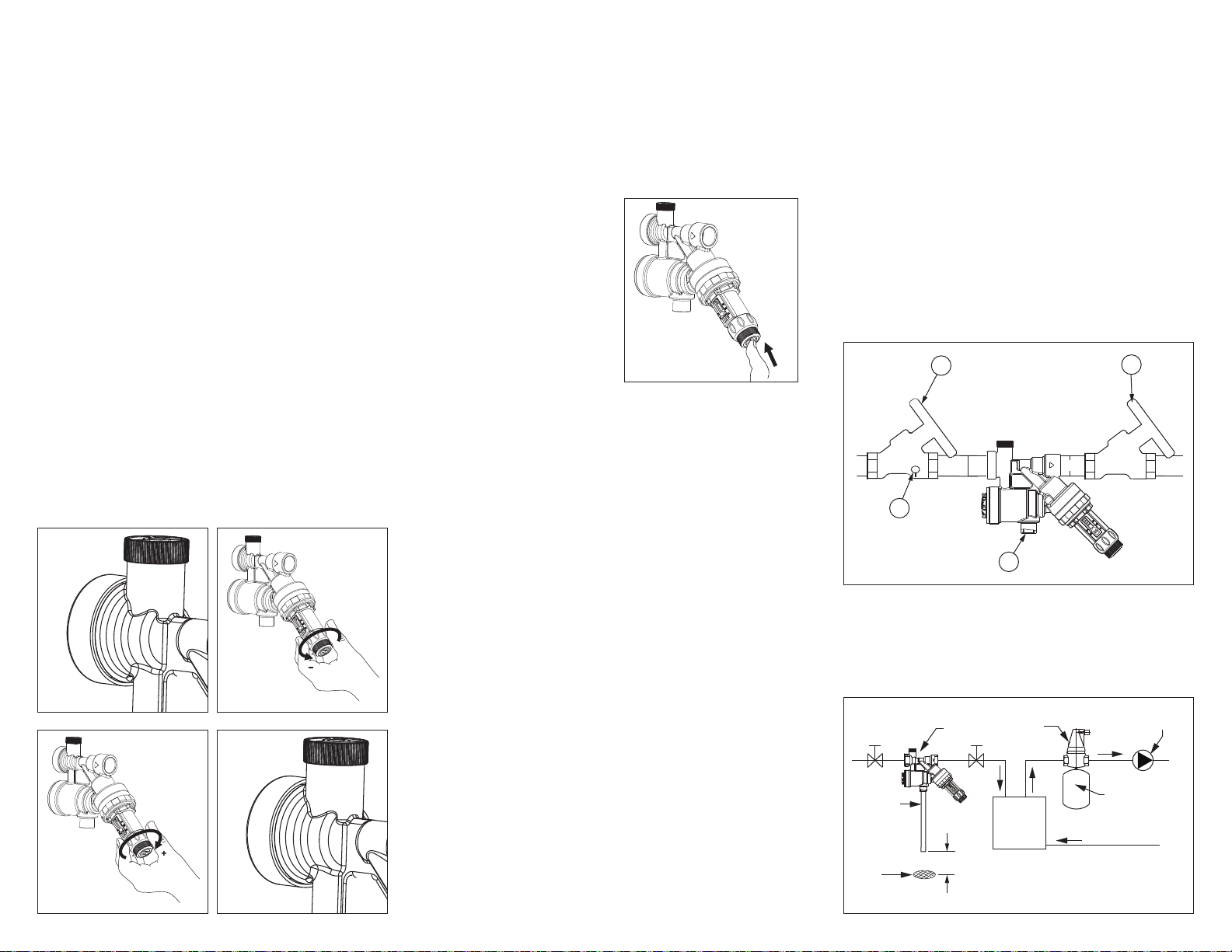
Flush the supply pipe to the valve prior to installation.
Install the combination valve so that the atmospheric
vent points downward toward the floor. With a properly
functioning and correctly installed valve water may be
released through the atmospheric vent. In order to prevent water damage during this release process a drain
pipe must be installed into the
1
⁄4"NPT vent connection.
The drain pipe should end well above a floor drain allowing
the flow of water to be easily seen and recognized. The
atmospheric vent connection or the drain pipe should
never be plugged or allowed to be shut off.
Setting and Maintenance of the Pressure Reducing
Valve:
The system pressure of the combination valve is factory set
to 12 PSI. Adjust the Pressure Reducing Valve as follows:
Important: In order to achieve accurate setting,
heating system adjustments must be done while
the system is at its cold fill temperature.
1. Ensure that the inlet pressure is at least 15 PSI
above the set pressure.
2. Turn the lock knob counter clockwise to loosen
(see figure 1).
3. To increase the system pressure, turn the adjusting knob clockwise (see figure 2).
4. To reduce the system pressure setting turn the
adjusting knob counter clockwise to the desired
set point (see figure 3).
Figure 1 Figure 2
Figure 3 Figure 4
5. Release any pressure above the required setting
via a suitable pressure release point in the system.
6. Once the desired pressure setting is reached turn
the lock knob clockwise until it is finger tight (see
figure 4).
To clean the integrated strainer in the pressure reducing
valve, close the isolating valve upstream and downstream of
the unit. Remove the PRV cartridge and clean with water.
Automatic Reset Fast Fill Feature:
With the Combination valves’
integrated fast fill feature you
can override the normal operation when filling and purging
the system. To activate the
fast fill feature, push in the
fast fill bottom on the end of
the PRV cartridge (see figure
5). When the fill pressure setting is reached the button will
pop out automatically, taking
the valve out of fast fill mode
and returning to the normal
Figure 5
operating mode.
NOTE: If the fast fill button is unintentionally pushed in
prior to installation it may be returned to the normal operating mode as follows.
1. Unscrew and remove the lock knob, carefully so
as not to lose the spring.
2. If the spring is still inside the lock knob, remove it.
3. Using a suitable tool, such as a small screwdriver
or pen, reach inside the lock knob and push the
button back out.
4. Put the spring back into the lock knob and screw
the knob back onto the cartridge.
Consult local code authorities for installation and testing
requirements in your area.
Note: This product should be installed by professionals
familiar with the correct function and performance of
hydronic heating systems and their associated components.
This device shall not be installed in a concealed or inaccessible location, or where venting of water from the
device during its normal functioning may be deemed
objectionable.
Caution: Protect the valve from freezing and exposure to
chemicals or solvents.
Test Procedure:
To test the secondary check valve, reduce the pressure
in the upstream pressure zone by proceeding as follows:
1. Fully close the first isolating valve (1).
2. While watching the atmospheric vent (4), open
the drain (3), this empties the water between the
backflow and the isolating valve.
3. When the check valve works properly, only a
very small quantity of water is drained through
the atmospheric vent (4)
4. If water continues to drain from the atmospheric
vent the backflow cartridge will need to be
cleaned or replaced. Follow the instructions for
cartridge replacement in order to remove it for
inspection. Inspect it for blockage or a build up of
impurities. Based on the visual inspection either
clean the cartridge with water or replace it with a
new one.
1 – First Isolating Valve, without Drain
2 – Second Isolation Valve
3 – Drain
4 – Atmospheric Vent
Installation Diagram:
 Loading...