

Page 1
Instruction Sheet
102-067
Timer and Aquastat
SUPERSEDES: November 15, 1992 EFFECTIVE: May 1, 2003
Plant ID# 001-979
Application:
The Taco Clock Timer/Temperature Aquastat combination is
designed to cycle the circulator during peak demand periods. The Analog Timer (No. 265-1) is adjustable to 15 minute
intervals within a 24 hour time frame. The Digital Timer
(No. 265-3) can be programmed for 7 day operation. The
Temperature Aquastat (No. 563-2) automatically switches
the circulator ON at 95ºF and OFF at 115ºF. The two can
be used in combination, or they can be used separately.
When the Clock Timer/Temperature Aquastat are used
together, the Timer switches ON sending power to the unit.
The Temperature Aquastat measures the temperature, and
cycles the circulator as long as the Timer is switched to the
ON mode.
If used separately, the Clock Timer operates the circulator
during the chosen number of ON/OFF intervals. When using
only the Temperature Aquastat, the circulator cycles intermittently to maintain a temperature between 95ºF and 115ºF.
The Clock Timer and Temperature Aquastat are easy to
retrofit to any “00” Series Circulator. The user-friendly 24
hour analog clock has an hour hand, raised minute hand
for ease of adjustment, two directional arrows, and AM/PM
time settings. Our easy to program digital timer provides
maximum convenience, comfort and energy savings. The
Clock Timer can be mounted in any direction by just
attaching it to the capacitor box electrical connection hole.
Electrical Hook-Up:
1. All electrical work must be performed by an electrician
in accordance with the latest edition of the National
Electrical Codes and Local Codes and Regulations.
2. Verify that the voltage, phase and frequency are correct
for the Circulator, Timer and Aquastat prior to connection.
3. Follow the appropriate wiring diagram
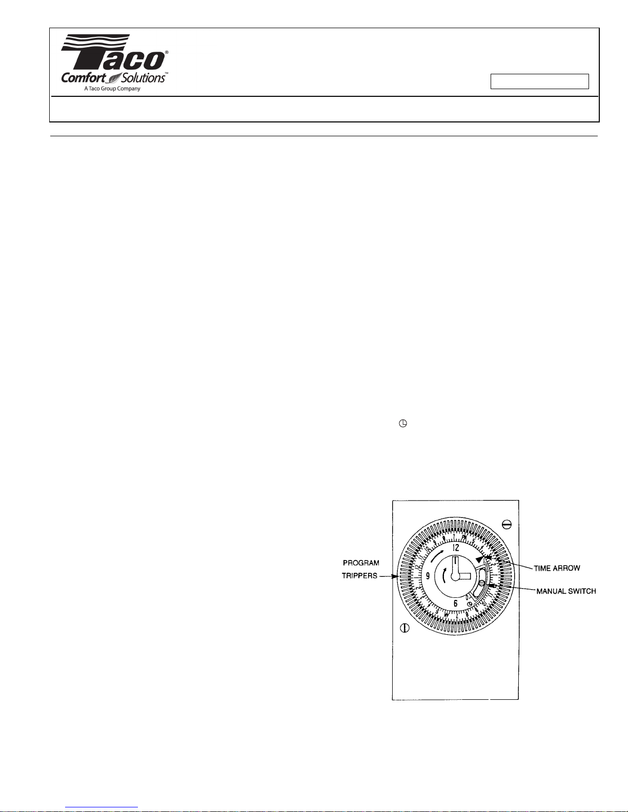
Analog Timer Programming:
1. Set the clock to the exact time of day using the clock
face minute hand. Pay special attention to the corresponding AM and PM settings.
2. Supply power. Test circulator by pushing Timer lever into
the manual position.
3. Set the desired ON/OFF times in 15 minute intervals.
Push trippers away from clock face for ON operation, and
leave trippers toward the clock face for OFF operation.
Programming Modes:
1. Up = On, Constant
circulation I
2. Middle = Automatic
operation
3. Down = Off O
Installation: FOLLOW ALL INSTRUCTIONS IN THE
SEQUENCE THAT THEY APPEAR.
Analog Timer Installation Instructions:
1. Disconnect the electrical supply. Remove circulator
terminal box screw and cover.
2. Loosen Timer box cover screw and remove cover.
3. Assemble the back portion of the Timer to the “00” terminal box as shown in the Timer installation diagram
(006 circulator pictured). Make sure that the protruding
tang on the back of the Timer box fits under the circulator’s terminal box base. Adjust until the two terminal
box openings are aligned.
4. Secure the locknuts. Feed the yellow and white circulator lead wires into the Timer through the bushing.
Reassemble circulator terminal box cover and secure
with the screw.
5. See electrical hook-up for Timer wiring.
Aquastat Installation Instructions:
1. Disconnect the electrical supply. Securely fasten the
Aquastat clip to
1
⁄2" pipe applications. The Aquastat must be properly
fastened to insure a good reading.
2. See electrical hook-up for Aquastat wiring.
3
⁄4" pipe or to the circulator casing for
Analog Timer Clock Face
Page 2
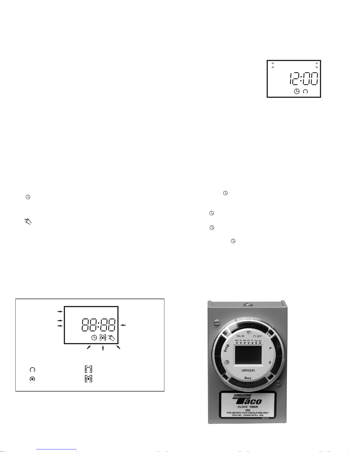
Digital 7 Day Programmable Timer:
The Plumb n’ Plug digital timer features a large LCD display
and unique “circular programming” with large keys for easy
setting and adjustments. A 100 hour capacitor backup
retains program memory during power outages.
Note: Although the Plumb n’ Plug digital timer contains
some degree of spike and electrical noise protection, as
with all electronic devices, these units can be affected by
electrical noise. It is recommended that they be powered
from a voltage source that has no switching devices or
inductive loads connected.
Digital Timer Technical Data:
Channels: 1
Programs: 20
Daylight time changeover: Manual
Manual 3-way override: On-Auto-Off
Shortest switching time: 1 minute
Reserve carryover: 100 hrs.
Input voltage: 120 VAC
Switching Output: SPDT relay
Switch ratings: 500 W @ 125 VAC
Input draw: 4 VA
Input frequency: 50 or 60 Hz
Wiring connections:
1
⁄4" quick connect
Ambient temperature: -20°F to 140°F (-28°C to 60°C)
UL and Canadian UL recognized: File E83486
Keypad Description:
Setting the Time/Automatic Run Mode
Prog. Program Mode
Res.* Reset: Clears all programs and time
Select ON or OFF in Prog. Mode, Manual Override
in Run Mode
±1h* Manual Daylight Change Key
h Setting the Hour (12:-- AM)
m Setting the Minute (12:01 AM)
Day Set Day(s) for time and programs
(Mon = 1, Tues = 2, . . . Sun = 7)
* Recessed keys; use a pen point to press
LCD Display Elements:
The LCD incorporates a number of different elements to display various data and information.
Programs:
The PNP digital timer will accept up to 20 programs. A program consists of:
1. An ON or OFF command
2. Time of day (Hour and Minute)
3. Single day or multiple days
A program is required for each ON
event, and a program is required
for each OFF event.
IMPORTANT: BEFORE PRO-
1 2 3 4 5 6 7
AM
CEEDING WITH SETTING THE
TIME AND PROGRAMMING THE
UNIT, PRESS THE RESET KEY TO
CLEAR ALL DATA FROM MEMORY.
Selecting AM/PM or Military Time:
After pressing reset, the display may show AM (right). The
numbered day symbols will be flashing on and off.
If the display does not show AM, it is in military time mode
(24:00 hr.). To change to AM/PM mode, press and hold the
h key and press the ±1h key once. AM will appear in display.
If display is in AM mode and military mode is desired, press
and hold the h key, press the ±1h key once.
Setting the Time:
NOTE: If the h and m keys are held down longer than 2 sec-
onds, the numbers will advance rapidly.
Press and hold the key during the following: (If Daylight
Savings Time is in effect, press ±1h first.)
1. Press h to advance to the current hour (while holding
down the key).
2. Press m to advance to the current minute (while holding
down the key).
3. Press Day repeatedly to advance to current day (while
holding down the key).
(Mon = 1, Tues = 2, . . . Sun = 7)
NOTE: If the days are flashing, it indicates the day of the
week was not set when setting the time. The timer cannot
be programmed unless the day of the week is entered.
Manual Daylight Time Changeover:
Each year, in the Spring, press ±1h to advance the time an
hour. In the Fall, press ±1h to set back an hour.
Days of the Week
Daylight Time Symbol
AM and PM Symbol
Run Mode Symbol
OFF Symbol
ON Symbol
1 2 3 4 5 6 7
+1h
AM
ON/OFF Symbol
Continuous OFF Symbol
Continuous ON Symbol
Time of Day or
Switching Time
Manual Override ON
Digital 7 Day Programmable Timer
Page 3

Programming 24 Hour or 7 Day Schedules:
Note: It is helpful to write out the program schedules before
beginning. See last page.
IMPORTANT: THE CURRENT TIME OF DAY AND DAY OF
WEEK MUST BE SET PRIOR TO PROGRAMMING. SEE
“SETTING THE TIME”.
EXAMPLE (see back page)
Program 1: ON at 7:00 AM Monday thru Friday
Program 2: OFF at 8:00 AM Monday thru Friday
Program 3: ON at 8:00 AM Saturday and Sunday
Program 4: OFF at 9:00 AM Saturday and Sunday
Four programs need to be entered.
Press Prog. key only once. Display shows:
1 2 3 4 5 6 7
AM
Program 1: ON at 7:00 AM Monday thru Friday
Press key once ON symbol appears
Press h key To 07 AM
Press m key once To 00
Press Day key 2 times 1 2 3 4 5 is displayed
Press Prog. key to enter
Program 2: OFF at 8:00 AM Monday thru Friday
Press key twice OFF symbol appears
Press h key To 08 AM
Press m key once To 00
Press Day key 2 times 1 2 3 4 5 is displayed
Press Prog. key to enter
Program 3: ON at 8:00 AM Saturday and Sunday
Press key once ON symbol appears
Press h key To 08 AM
Press m key once To 00
Press Day key 3 times until only 6 & 7 is displayed
Press Prog. key to enter
Program 4: OFF at 9:00 AM Saturday and Sunday
Press key twice OFF symbol appears
Press h key To 09 AM
Press m key once To 00
Press Day key 3 times until only 6 & 7 is displayed
Press Prog. key to enter
Program additional settings as desired (maximum of 10
ON/OFF programs). When all programs are complete,
press key to enter Run Mode.
IMPORTANT: IF AN “ON” TIME WAS PROGRAMMED
THAT IS EARLIER IN THE DAY THAN THE CURRENT TIME,
PRESS ONCE TO TURN THE TIMER “ON”. (IT DOES
NOT “LOOK BACK” TO DETERMINE IF IT SHOULD BE ON
OR OFF AFTER PROGRAMMING.)
NOTE: If 24 hour time control (same schedule every day of
the week) is desired, ignore Day key.
If an ON or OFF symbol is not entered, the ON symbol will
flash, and program will not be accepted.
Day Key Selections:
Press Day Key Display Shows Days
0 times 1 2 3 4 5 6 7 Every Day
1 time 1 2 3 4 5 6 Mon - Sat
2 times 1 2 3 4 5 Mon - Fri
3 times 1 2 3 4 5 6 7 Sat & Sun
4 times 1 Monday
5 times 1 2 Tuesday
6 times 1 2 3Wednesday
7 times 1 2 3 4 Thursday
8 times 1 2 3 4 5 Friday
9 times 1 2 3 4 5 6 Saturday
10 times 1 2 3 4 5 6 7 Sunday
Reviewing Programs:
To review the programs at any time, press Prog. key.
Programs will appear in the order they were entered with
repeated presses of the Prog. key. After all programs have
been reviewed, the blank display will appear to allow entering another program. Another press of the Prog. key will
display the number of free programs available, such as Fr 16
if 4 programs have been entered.
Manual Override:
TEMPORARY: While in the Run Mode,
•Pressing the key once will reverse the output; ON to
OFF or OFF to ON. The symbol appears in the display to indicate a temporary override. At the next scheduled switching time, automatic control resumes, eliminating the override.
CONTINUOUS: While in the Run Mode,
•Pressing the key twice will turn the output to ON permanently. symbol appears in display.
•Pressing the key three times will turn the output OFF
permanently. symbol appears in display.
•To terminate a continuous override, press the key
until appears in the display.
Changing a Program:
Select the program to be changed with the Prog. key. A
new set of days may be selected with the Day key just as
in initial programming. Hour and minute can be changed
with the h and m keys.
Press Prog. or key to store the new program.
Deleting a Program:
To delete only one or a few programs:
Press Prog. key until the desired program is displayed.
Press m key to :59 and press once more to blank out.
Press h key to 11PM and press once more to blank out.
Press key, display will flash for several seconds and
then enter the Run Mode.
Using the reset key will delete ALL programs, the time of
day, and day of the week.
Page 4

Troubleshooting:
TIMER
BLACK
WHITE
YELLOW
NEUT. WHITE
YELLOW MOTOR LEAD
WHITE MOTOR LEAD
GND
SCREW
PUMP
LINE BLACK
WHITE
BLACK
AQUASTAT
5 4 3 2 1
TIMER
BLACK
WHITE
YELLOW
NEUT. WHITE
YELLOW MOTOR LEAD
WHITE MOTOR LEAD
GND
SCREW
PUMP
LINE BLACK
5 4 3 2 1
BLACK
WHITE
NEUT. WHITE MOTOR LEAD
YELLOW MOTOR LEAD
GND
SCREW
PUMP
LINE BLACK
AQUASTAT
THREADED PIPE
LOCKNUT
SPACER
RING
PUMP TERMINAL BOX
PUMP
TIMER MODULE BACK
PROBLEM: Days are flashing, pressing any key does nothing except key turns output On and OFF.
SOLUTION: Time of Day and Day of Week have not been
set. See “Setting the Time”.
A second, but very unlikely cause of loss of program, is a
power failure with the backup capacitor low or dead. Check
by disconnecting power and monitoring how long the
capacitor keeps the time of day in the display. Typically, the
capacitor will maintain the time and programs for 4 days,
but not more than 5 days.
PROBLEM: Time of day was set while holding the key
down, but days are still flashing.
SOLUTION: Current day of week was not set while holding
down the key. See “Setting the Time”.
PROBLEM: It is 10 AM and an ON program for 8 AM was
entered, but the output is not ON. Display shows the
and symbols.
SOLUTION: After programming, the timer does not “look
back” to determine if it should be ON. Press the key
(temporary override) to turn the output ON; appears
in display. The timer will assume automatic operation at the
next programmed event.
PROBLEM: A program for 8 AM Monday thru Friday was
entered, but it will not accept it and is flashing.
SOLUTION: The ON or OFF was not entered as part
of the program. On or OFF must be selected.
Timer and Aquastat Wiring Diagram
Timer Only Wiring Diagram
PNP Digital Timer Program Schedules (Example)
Program ON/OFF h m Day(s)
1On7 AM 00 Mon., Tue., Wed., Thurs., Fri.
2Off8 AM 00
3On8 AM 00
4Off9 AM 00
Timer Installation Diagram
(006 Circulator Shown)
Mon., Tue., Wed., Thurs., Fri.
Saturday and Sunday
Saturday and Sunday
Aquastat Only Wiring Diagram
DOITONCE. DOITRIGHT.
TACO, INC., 1160 Cranston Street, Cranston, RI 02920 Telephone: (401) 942-8000 FAX: (401) 942-2360.
TACO (Canada), Ltd., 6180 Ordan Drive, Mississauga, Ontario L5T 2B3. Telephone: 905/564-9422. FAX: 905/564-9436.
Visit our web site at: http://www.taco-hvac.com
™
Printed in USA
Copyright 2003
TACO, Inc.
 Loading...