

Page 1
102-361
Instruction Sheet
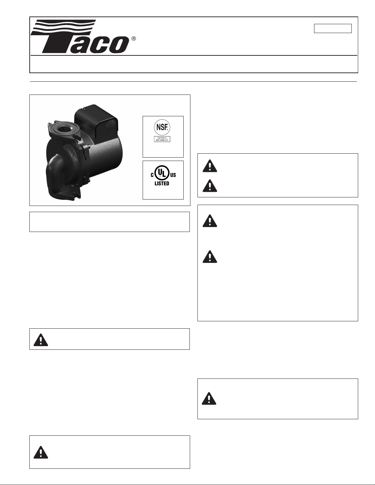
2400 Series Hi-Capacity Circulator
SUPERSEDES: June 15, 2014 EFFECTIVE: December 19, 2014
Plant ID# 001-3932
3. Remove capacitor box cover and disconnect electrical
supply lines to pump.
4. Loosen flange bolts and shift pump body slightly to
relieve any remaining system pressure.
5. Remove flange nuts/bolts and pump from system.
STAINLESS STEEL
MODELS ONLY
OR INDOOR
F
SE ONLY
U
INSTALLER: Please leave these instructions for
owner’s use.
APPLICATION:
The Taco 2400 Series Hi-Capacity circulators are designed
for use on a wide range of hydronic heating, cooling or
domestic hot water recirculating systems. Features include
a compact, quiet running, close-coupled, thermally protected motor assembly with permanent split-capacitor and permanently lubricated bearings. A stainless steel shaft, silicon-carbide mechanical seal and non-ferrous impeller
make the 2400 Series circulator an ideal choice for years of
maintenance-free operation.
Note: Use Stainless Steel body circulators on open
systems for the best corrosion protection.
INSTALLATION OF 2400 SERIES CIRCULATOR:
WARNING: Do not use in swimming pool or spa
areas; pump has not been investigated for this
application.
WARNING: To avoid electrical shock, disconnect the
power supply to the circulator and the main electrical
unit.
CAUTION: When installing electrical connections,
do not apply mechanical loads to the capacitor
box; otherwise, retaining screws may be pulled out
of the housing, making circulator unusable.
CAUTION:
1. The addition of petroleum based fluids or certain chemical additives to systems utilizing TACO
equipment voids the warranty.
2. Use supply wires suitable for 90°C – ATTENTION: Employer des fils d´alimentation adequats
pour 90°C.
CAUTION: Installations at higher elevations over
5000 feet must have higher fill pressure of 20 psi
minimum to prevent pump cavitation and flashing.
Premature failure may result. Adjust expansion
tank pressure to equal fill pressure. A larger size
expansion tank may be required.
CAUTION: Taco 2400 Series circulators are
designed for indoor use only.
OPERATING SPECIFICATIONS:
• Maximum Working Pressure: 150 psi (1034 kPa)
• Maximum Operating Temperature: 225ºF (107ºC)
• Electrical Rating: 115V/60Hz/1Ph or 230V/60Hz/1Ph
REMOVAL OF EXISTING PUMP FROM SYSTEM PIPING:
1. Disconnect and lock-out electrical supply to pump.
2. Close isolation valves on suction and discharge sides
of pump. If valves are not installed, the system may
need to be drained.
CAUTION: To prevent injury, allow system
water to cool to 100ºF before removing old
pump or draining system. Leave drain valve
open until service/replacement is complete.
A. Location:
• Install pump with sufficient room for future inspection,
maintenance and service.
• It is recommended that isolation valves be installed on
the pump suction and discharge to simplify future ser-
CAUTION: This pump has a mechanical seal
which may require service. Allow access for
periodic inspection and leak detection.
Provide adequate drainage to prevent property damage.
vice or replacement without draining the system.
1. Using teflon tape or high quality thread sealant, install
Taco companion flanges on threaded pipe ends to
ensure proper fit-up and leak protection. (See Table 1
for companion flange set specifications.)
Page 2
2. Minimize pipe strain on pump by using pipe hangers on
FLOW
NOT RECOMMENDED
RECOMMENDED
FLOW
FLOW
FLOW
the suction and discharge lines.
. Position vertical and horizontal piping so bolt-holes on
3
pump and companion flanges match. Do not force the
uction and discharge lines into position. This may cre-
s
ate excess stress on the pump casing and flanges.
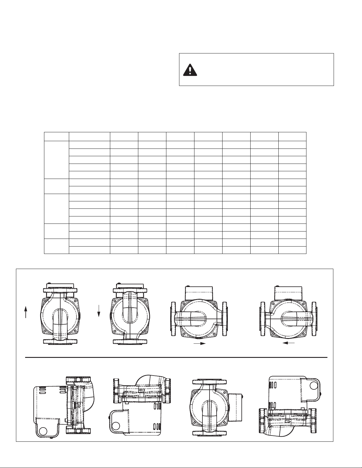
B. Mounting Position:
Always install pump with the motor shaft in the horizon-
•
tal position and the capacitor/conduit box oriented on
top of the motor housing, as shown in Fig. 1.
Table 1 – 2400 SERIES COMPANION FLANGE SETS
Models Connection
Iron NPT 110-251F 110-252F 110-253F 110-254F — — —
400-10
2
2400-20
400-45
2
400-50
2
400-50/2
2
", 2 Bolt
2
2400-30
2400-40
2400-60
2400-65
2400-70
2400-70/3
3", 4 Bolt
Stainless Steel NPT 110-251SF 110-252SF 110-253SF 110-254SF — — —
Bronze Sweat 110-523BSF 110-524BSF 110-525BSF 110-526BSF — — —
hut-Off NPT
S
hut-Off Sweat
S
ron NPT
I
Stainless Steel NPT — — — — 194-2124SF — —
ron NPT
I
Stainless Steel NPT — — 194-1540SF 194-1542SF — — —
Shut-Off NPT — — SF-125T-0012 SF-150T-0012 — — —
Shut-Off Sweat — — SF-125S-0012 SF-150S-0012 — — —
Iron NPT — — — — 185-086C — —
Bronze NPT — — — — 185-086B — —
Iron NPT — — — — — 185-112C 185-113C
Bronze NPT — — — — — 185-112B 185-113B
3
⁄4" 1" 11⁄4" 11⁄2" 2" 21⁄2" 3"
F-075T
S
F-075S
S
—
—
F-100T
S
F-100S
S
—
—
• Standard pump body mounting position is with the flow
in the up-discharge direction (body position #3). The
pump body may be field-rotated in any direction to
accommodate system piping and flow direction.
CAUTION: Do not support, suspend or brace
pump motor or early failure may result.
Support provided by casing is sufficient for
tructural integrity of pump
s
F-125T
S
F-125S
S
—
94-1540F194-1542F
1
F-150T
S
F-150S
S
—
—
—
94-2124F
1
—
—
—
—
—
—
—
—
—
Fig. 1 – Installation Positions
Page 3
• Be sure to align the arrow on the casing with desired
flow direction.
C. Electrical Wiring:
• All electrical wiring must be installed by a licensed electrician in accordance with local and national codes and
regulations.
•Electrical supply and grounding wires must be suitable
for at least 90ºC (194ºF).
• 2400 Series circulators are thermally protected and do
not require external overload protection.
1. Be sure all electrical power to pump is disconnected
and locked-out before proceeding with wiring.
2. Loosen capacitor/conduit box screw and remove cover.
3. Attach appropriate size connector to one of the two
knock-out holes in the capacitor/conduit box.
4. Using minimum 18 AWG wire, connect the hot and neutral leads from the electrical supply to the respective
black and white leads in the capacitor box.
5. Connect the ground wire to the green ground screw in
the capacitor box.
6. Replace capacitor/conduit box cover.
CAUTION: Do not start the pump until the system has been completely filled and vented.
Running the pump dry may damage the
mechanical seal and void warranty.
7. Insert plastic plug provided in unused knock-out hole.
SYSTEM START-UP:
CAUTION: The majority of mechanical seal
failures are due to poor media (fluid) quality
in the system. To maximize seal life, media
quality must be maintained in the system,
and TDS (Total Dissolved Solids)/TSS (Total
Suspended Solids) should not exceed
500ppm with standard Carbon/SiliconCarbide seals. The use of inhibitor based
glycols is acceptable, but additional
inhibitors should not be added. Always follow the glycol manufacturer’s specification
for system preparation and water quality.
Treatment with silicates should not be used.
Failure to maintain media quality will void the
standard Taco warranty.
1. Prior to pump start-up, the system should be thoroughly
cleaned, flushed and drained to prevent damage to
seal surfaces.
2. Open isolation valves and re-fill system with clean water.
Check for any leaks.
3. Vent all air from system at an air vent located at the
high point in the system.
4. Start circulator to check for proper operation.
PERIODIC INSPECTION, MAINTENANCE:
Taco 2400 Series Hi-Capacity circulators are designed to
provide years of trouble-free service. However, periodic
inspection and routine maintenance are recommended for
all hydronic systems and mechanical equipment. If any evidence of leakage or damage is present, take preventive
steps to repair or replace the circulator immediately.
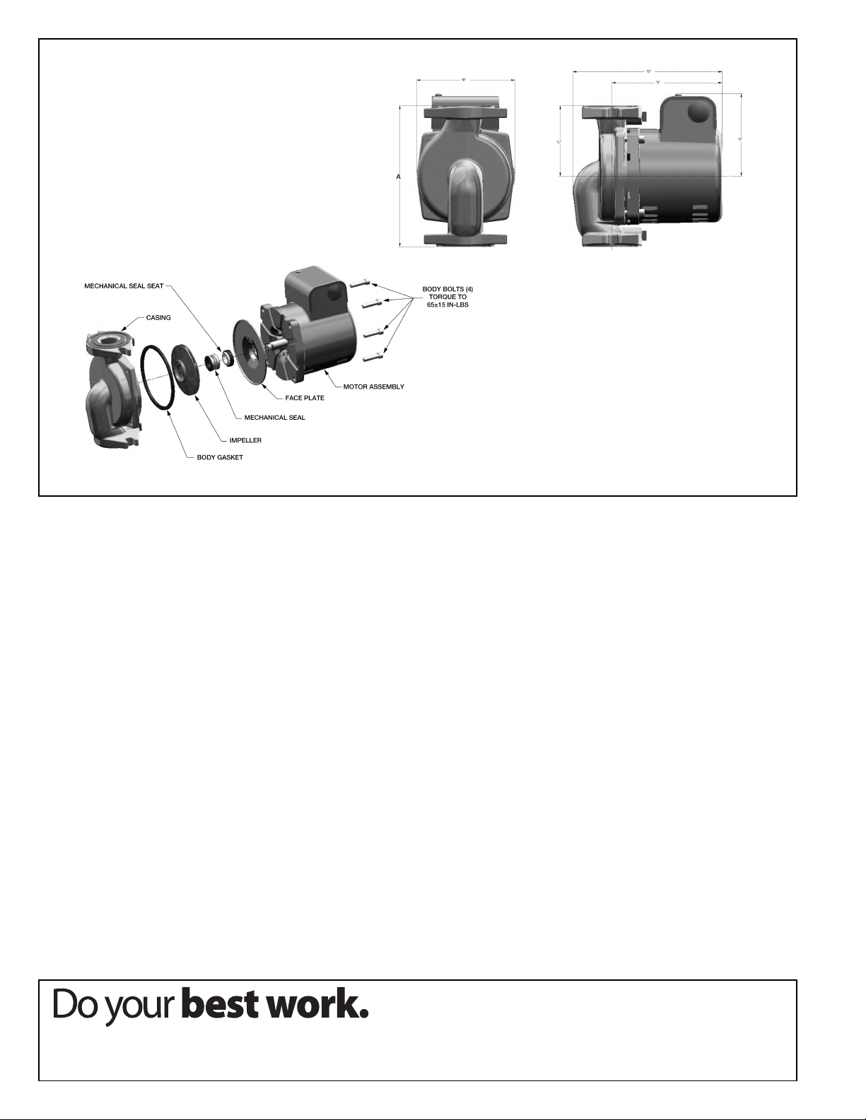
REPLACING THE MECHANICAL SEAL: Refer to Fig. 2
on back page.
1. Follow steps 1 thru 5 in section “Removal of existing
pump from system piping”.
2. Loosen the four body bolts that attach the motor housing to the casing. While supporting the motor, remove
the four bolts and carefully remove the motor and
impeller assembly from the casing.
CAUTION: Do not allow screwdriver to make
contact with motor windings or insulation.
Permanent damage to motor may result.
3. To remove the impeller, first insert a screwdriver into
the motor ventilation slots to make contact with one of
the rotor cooling fins. While locking the rotor in place
with the screwdriver, turn the impeller clockwise to
loosen and remove from shaft.
4. Remove the seal assembly from the shaft.
5. Remove the face plate from the motor housing. To
remove face plate, gently pry it away from the housing.
6. Remove the old seal seat and cup. Lubricate the new
cup with soapy water and install new parts in the face
plate recess. Replace the face plate to its original position. Carefully tap the face plate evenly into the recess
in the motor housing.
7. Clean the impeller shaft before installing the new seal.
8. Lubricate the impeller shaft with soapy water. Do not
install new seal on a dry impeller shaft or damage to
seal may result.
9. Slide the new carbon seal and spring assembly onto
the shaft until it contacts the silicon-carbide seal seat.
CAUTION: Do not allow screwdriver to make
contact with motor windings or insulation.
Permanent damage to motor may result.
10. While holding the rotor in place as in Step 3, thread the
impeller onto the shaft in a counter-clockwise
until it stops. Check to make sure the pump will rotate.
If the impeller will not spin freely, contact Taco Technical
Support at 1-401-942-8000.
11. Remove old body gasket and replace with new gasket
provided in seal kit. Press gasket into seal face plate,
then attach motor to casing. Use caution not to pinch
body gasket or leaks may result.
12. Attach the pump casing to the motor housing and
secure with the four body bolts. Be sure flow arrow is
pointing in proper direction. Tighten the four bolts evenly in a criss-cross pattern to 65 (+/-15) in-lb of torque.
13. Re-install circulator into system using new flange
gaskets. Refer to section “Installation of 2400 Series
Circulator” for complete mounting and wiring instructions.
direction
Page 4
LIMITED WARRANTY STATEMENT
Taco, Inc. will repair or replace without charge
(at the company’s option) any Taco 2400 Series
circulator or circulator part which is proven
defective under normal use within three (3)
years from the date of manufacture.
In order to obtain service under this warranty, it
is the responsibility of the purchaser to promptly
notify the local Taco stocking distributor or Taco
in writing and promptly deliver the subject product
or part, delivery prepaid, to the stocking distributor. For assistance on warranty returns, the purchaser may either contact the local Taco stocking distributor or Taco. If the subject product or
part contains no defect as covered in this warranty, the purchaser will be billed for parts and
labor charges in effect at time of factory examination and repair.
Any Taco product or part not installed or operated
in conformity with Taco instructions or which has
been subject to misuse, misapplication, the addi-
Fig. 2: Exploded View of Pump
tion of petroleum-based fluids or certain chemical additives to the systems, or other abuse, will
not be covered by this warranty.
If in doubt as to whether a particular substance
is suitable for use with a Taco product or part, or
for any application restrictions, consult the
applicable Taco instruction sheets or contact
Taco at (401-942-8000).
Taco reserves the right to provide replacement
products and parts which are substantially similar
in design and functionally equivalent to the
defective product or part. Taco reserves the right
to make changes in details of design, construction, or arrangement of materials of its products
without notification.
TACO OFFERS THIS WARRANTY IN LIEU OF
ALL OTHER EXPRESS WARRANTIES. ANY
WARRANTY IMPLIED BY LAW INCLUDING
WARRANTIES OF MERCHANTABILITY OR
FITNESS IS IN EFFECT ONLY FOR THE DURA-
TION OF THE EXPRESS WARRANTY SET
FORTH IN THE FIRST PARAGRAPH ABOVE.
THE ABOVE WARRANTIES ARE IN LIEU OF
ALL OTHER WARRANTIES, EXPRESS OR
STATUTORY, OR ANY OTHER WARRANTY
OBLIGATION ON THE PART OF TACO.
TACO WILL NOT BE LIABLE FOR ANY SPECIAL, INCIDENTAL, INDIRECT OR CONSEQUENTIAL DAMAGES RESULTING FROM THE
USE OF ITS PRODUCTS OR ANY INCIDENTAL
COSTS OF REMOVING OR REPLACING
DEFECTIVE PRODUCTS.
This warranty gives the purchaser specific rights,
and the purchaser may have other rights which
vary from state to state. Some states do not
allow limitations on how long an implied warranty
lasts or on the exclusion of incidental or consequential damages, so these limitations or exclusions may not apply to you.
TACO, INC., 1160 Cranston Street, Cranston, RI 02920 Telephone: (401) 942-8000 FAX: (401) 942-2360.
TACO (Canadá), Ltd., 8450 Lawson Road, Unit #3, Milton, Ontario L9T 0J8. Telephone: 905/564-9422. FAX: 905/564-9436.
Visit our web site at: http://www.taco-hvac.com
Printed in USA
Copyright 2014
TACO, Inc.
 Loading...