

Page 1

102-557
Instruction Sheet
0018eTM ECM High-Efciency Circulator
Featuring Bluetooth® Communication
SUPERSEDES: NEW EFFECTIVE: March 22, 2019
Plant ID No. 001-5012
DESCRIPTION:
The 00e® series 0018eTM circulator is a variable speed wet rotor circulator with an ECM, permanent magnet
motor. Operating modes include innitely variable xed speed, constant pressure, proportional pressure,
and activeADAPT
0018eTM ECM Circulator Mobile App using Bluetooth® connectivity on your smartphone or tablet. The ECM
high-efciency motor reduces power consumption by up to 85% compared to equivalent AC permanent split
capacitor circulators.
TM
self-adjusting proportional pressure. Adjust the operating mode with the dial or the Taco
Figure 1:
APPLICATION:
• Maximum operating pressure: 125 psi (8.6 bar)
• Maximum water temperature: 230°F (110ºC)
• Electrical specications:
Voltage: 110-120V, 50/60 Hz, single phase
Maximum operating power: 44W
Maximum amp rating: 0.54
• Equipped with a cast iron casing and should be used for closed loop systems only
• Not suitable for open loop potable water or chilled water systems
• Taco circulator pumps are for indoor use only – employer uniquement a l’interieur
• Acceptable for use with water or maximum of 50% water/glycol solution
Standard ange model: 0018e-F2
Part #: VR1816-HY2-FC2A01
FEATURES:
• 3 operating modes in dial activation:
- Proportional pressure ( TRV - Panel Radiator ), variable speed - 2 variable pressure
differential settings (Med or High)
- Constant pressure ( ZV - Zone Valve ), variable speed - 2 constant pressure
differential settings (Med or High)
- Fixed speed ( ZONE CIRC - zoning with circulators ) - innitely adjustable MIN/MAX settings
• 4 operating modes in 0018e
- Fixed Speed - innitely adjustable MIN/MAX settings
- Constant Pressure - variable speed - 9 constant pressure differential settings
- Proportional Pressure - variable speed - 9 variable pressure differential settings
- activeADAPTTM - Designed for constant circulation systems. Automatically adjusts
to system conditions
• Multi-color LED display showing operating mode and error code diagnostics
• Use with a Taco ZVC Zone Valve Control or SR Switching Relay for ON/OFF operation
• Nut capture feature on anges for easier t up
• Dual electrical knockouts and 6” stranded wire leads for easy wiring
• Double insulated - no ground-wire required
• Whisper quiet operation
• BIO Barrier® protects the pump from system contaminants
• SureStart® - automatic unblocking and air purging mode
• Optional 2-way ange model for easy t-up to any ange orientation
• Integral Flow Check (IFC®) included - Field installed
TM
Mobile App activation:
Optional 2-way ange model: 0018e-F4
Part #: VR1816-HY2-4C2A01
INSTALLATION:
WARNING: Do not use in swimming pool or spa areas. Pump has not been investigated for these applications.
AVERTISSEMENT: Ne pas utiliser dans une piscine ou un spa. La pompe n’a pas été étudiée pour ces applications.
CAUTION: The addition of petroleum based uids or certain chemical additives to systems using TACO equipment voids the warranty. Consult factory for uid
compatibility.
ATTENTION: L’ajout de liquides à base de pétrole ou de certains additifs chimiques à des systèmes utilisant un équipement TACO annule la garantie. Consultez
le fabricant pour connaître la compatibilité de liquides.
CAUTION: Installations at elevations over 5000 feet must have higher ll pressure of 20 psi minimum to prevent pump cavitation and ashing. Premature failure
may result. Adjust expansion tank pressure to equal ll pressure. A larger size expansion tank may be required.
ATTENTION: Des installations à des altitudes de plus de 1600 mètres doivent présenter une pression de remplissage plus élevée de 20 psi au minimum an
d’éviter toute cavitation ou ashing de la pompe. Une défaillance prématurée peut en résulter. Réglez la pression du réservoir d’expansion de façon qu’elle soit
égale à la pression de remplissage. Un réservoir d’expansion d’une taille supérieure peut être nécessaire.
1
Page 2
BOILER
FF
EXPANSION
TANK
ZONE 1ZONE 2
V1
PV4
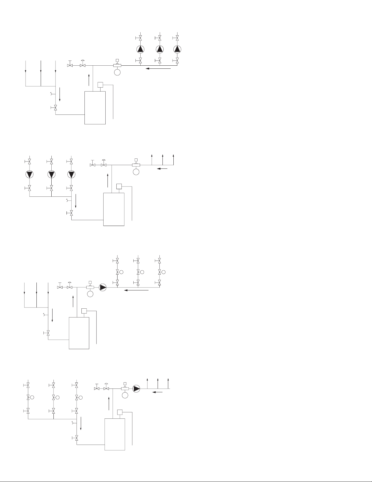
FIGURE 1:
MULTI-SPEED MODE
PREFERRED PIPING
FOR CIRCULATORS
ON BOILER SUPPLY
ZONE 1
V2
V3
P
ZONE 3
ZONE 2
V2
V3
P
ZONE 3
V2
V3
P
• AIR PURGING SEQUENCE
BY ZONE
LAST FIRST
FIGURE 1:
MULTI-SPEED MODE
Figure 2:
BOILER
FF
EXPANSION
TANK
ZONE 1ZONE 2
V1
PV4
FIGURE 2:
MULTI-SPEED OR VARIABLE SPEED MODES
PREFERRED PIPING
FOR ZONE VALVES
ON BOILER SUPPLY
ZONE 1
V2
V3
ZONE 3
ZONE 2
V2
V3
ZONE 3
V2
V3
• AIR PURGING SEQUENCE
BY ZONE
LAST FIRST
P
ZV1 ZV2 ZV3
M
M
M
FIGURE 2:
PREFERRED PIPING
FOR CIRCULATORS
ON BOILER SUPPLY
V3
ZONE 1
V3
ZONE 2
ZONE 3
V3
ZONE 3
PV4
ALTERNATE PIPING
FOR CIRCULATORS
ON BOILER RETURN
ZONE 3
V3
P
V2
ZONE 1ZONE 2
V1
ZONE 1ZONE 2
V3V3
PP
V2V2
PV4
V1
P
V2
FF
EXPANSION
TANK
P
P
V2
V2
LAST FIRST
• AIR PURGING SEQUENCE
BY ZONE
KEY:
VI, V2, V3 = SHUT-OFF ISOLATION VALVE
P = TACO CIRCULATOR WITH IFC
FF = FAST FILL BOILER FEED VALVE
PV4 = PURGE VALVE
RECOMMENDED PURGING STEPS:
BOILER
1. CLOSE V1, PV4, V2
2. OPEN V3
3. OPEN FF VALVE
4. OPEN V2, PV4, TO PURGE LAST ZONE
FIRST (ZONE 3)
5. CLOSE FF VALVE
6. CLOSE V2, PV4
ZONE1ZONE
ZONE
2
3
7. REPEAT STEPS 1 TO 6 FOR EACH
ADDITIONAL ZONE, PURGE ZONE 1 LAST
8. OPEN V1 WHEN ALL ZONES ARE PURGED
9. ADJUST SYSTEM TO DESIRED OPERATING
FILL PRESSURE IF REQUIRED
TANK
LAST FIRST
• AIR PURGING
SEQUENCE
BY ZONE
FF
EXPANSION
BOILER
Figure 3:
MULTI-SPEED OR VARIABLE SPEED MODES
PREFERRED PIPING
FOR ZONE VALVES
ON BOILER SUPPLY
ZONE 3
ALTERNATE PIPING
FOR ZONE VALVES
ON BOILER RETURN
ZONE 3
V3
ZV3 ZV2 ZV1
V2
ZONE 1ZONE 2
PV4
V1
M
M
FF
ZONE 1ZONE 2
V3V3
V2V2
BOILER
V3
V2
P
EXPANSION
TANK
M
FF
ZONE 1
ZV1 ZV2 ZV3
LAST FIRST
• AIR PURGING SEQUENCE
BY ZONE
EXPANSION
ZONE 2
M
ZONE1ZONE
LAST FIRST
P
V3
V2
• AIR PURGING
SEQUENCE
BY ZONE
V3
M
V2
TANK
ZONE 3
2
M
ZONE
KEY:
VI, V2, V3 = SHUT-OFF ISOLATION VALVE
P = TACO CIRCULATOR WITHOUT IFC INSTALLED
FF = FAST FILL BOILER FEED VALVE
PV4 = PURGE VALVE
ZV = ZONE VALVE
RECOMMENDED PURGING STEPS:
1. CLOSE V1, PV4, V2
2. OPEN V3 AND ZV3
3. OPEN FF VALVE
4. OPEN V2, PV4, TO PURGE LAST ZONE
FIRST (ZONE 3)
5. CLOSE FF VALVE
6. CLOSE V2, PV4
7. REPEAT STEPS 1 TO 6 FOR EACH
3
ADDITIONAL ZONE, PURGE ZONE 1 LAST
8. OPEN V1 WHEN ALL ZONES ARE PURGED
9. ADJUST SYSTEM TO DESIRED OPERATING
FILL PRESSURE IF REQUIRED
10. MOVE ALL ZV TO CLOSED/AUTOMATIC POSITION
PV4
BOILER
V1
2
Page 3
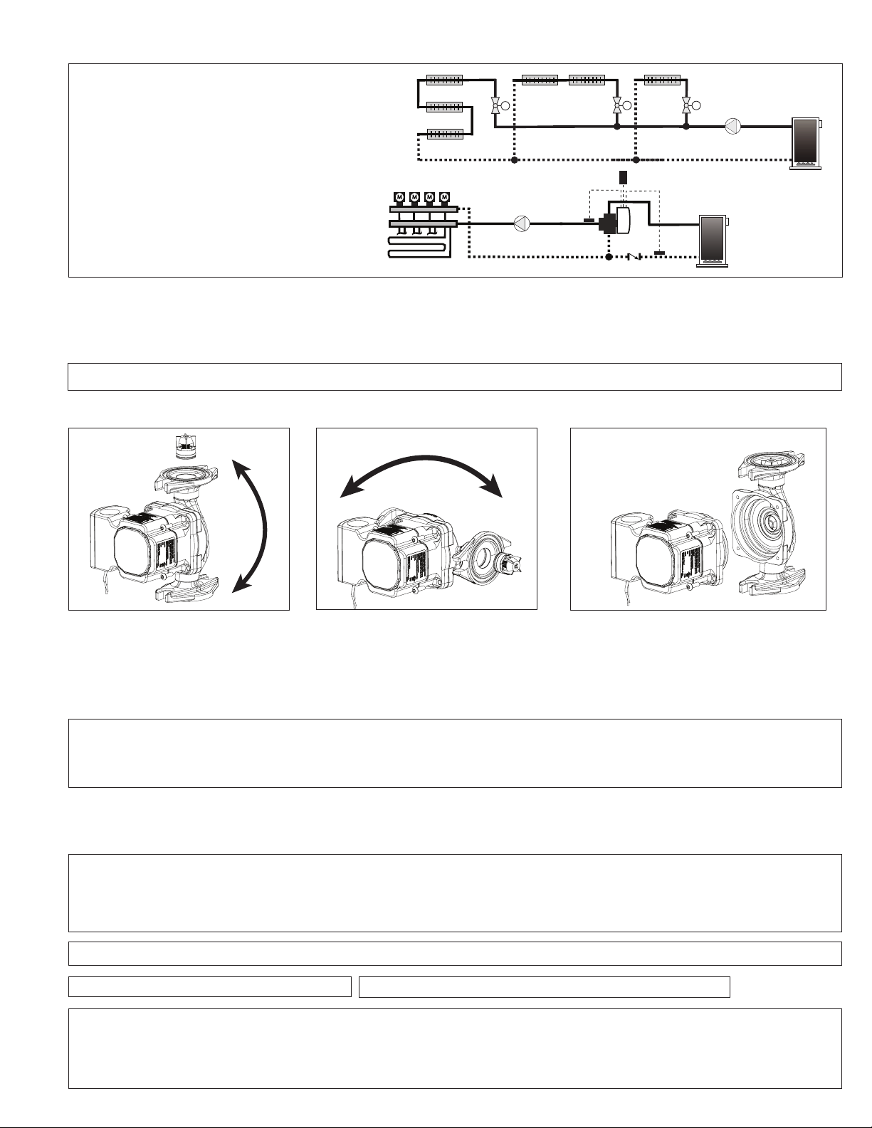
Typical Variable Speed Applications:
• Zone Valves
• Panel Radiation with
Thermostatic Valves
• Radiant Loops with
Actuators
Across a Series
Loop System Using
Zone Valves
M
M
M
- Varies speed to
maintain proportional
or constant pressure
differential (∆P)
M M M M
Across Multi-Zone
Radiant Manifolds
with Loop Actuators
Outdoor
Sensor
iSeries-R
B
B
C
C
A
A
Boiler
Sensor
1. Location: The circulator can be installed on the supply or return side of the boiler but for best system performance, it should
always pump away from the expansion tank. See piping diagrams in Figure 2 and Figure 3.
2. Mounting position: Circulator must be mounted with the motor in the horizontal position. See diagrams below for
acceptable motor mounting orientations.
CAUTION: Do not use at rubber gaskets. Only use O-ring gaskets provided or leaks may result. Warranty will be void.
Figure 4:
ACCEPTABLE MOTOR MOUNTING POSITIONS
Figure 5:
Spin casing
Spin
casing
to
change
ow
direction.
to change
ow direction.
Figure 6: Do not detach motor frame from pump
casing. Simply spin casing to the
proper ow direction.
CASING ROTATION
X
Always install with motor in horizontal orientation.
Position electrical junction box at 9 o’clock for best
viewing orientation. Pump casing may be rotated
to change ow direction. Locate the arrow on the
casing body to determine ow direction.
Integral Flow Check (IFC®) option - An IFC® is included in the carton. If required, press IFC into machined discharge port with plunger
and o-ring facing in, until it snaps into place. Before installing, press IFC plunger to be sure it moves freely. See diagram above.
CAUTION: To reduce the possibility of noise transmission, be sure to add vibration dampeners to piping when mounting circulator to wall
or oor joists.
ATTENTION: Pour réduire la possibilité de transmission de bruit, veillez à ajouter des amortisseurs de vibration à la tuyauterie lors du
montage du circulateur sur des chevêtres de mur ou de plancher.
3. Filling the system: Fill the system with tap water or a maximum of 50% propylene-glycol and water solution. The
system must be lled before operating the circulator. The bearings are water lubricated and should not be allowed to operate dry. Filling
the system will result in immediate lubrication of the bearings. It is always good practice to ush a new system of foreign matter before
startin the circulator.
WARNING: Risk of electric shock. To reduce the risk of electric shock, be certain that it is connected only to a properly grounded, grounding-type receptacle. Follow all local electrical and plumbing codes.
AVERTISSEMENT: Risque de choc électrique. Pour réduire le risque de choc électrique, veillez à ce qu’elle soit raccordée uniquement à un
réceptacle de type mise à la terre proprement mis à la terre. Respectez tous les codes de plomberie et électriques locaux.
WARNING: Use supply wires suitable for 90°C. AVERTISSEMENT: Employer des ls d’alimentation adeqauts pour 90°C.
WARNING: Disconnect power when servicing.
To rotate the pump casing, remove the 4 motor screws. When rotating pump casing position, DO NOT detach
motor housing from the casing. Damage to the casing O-ring and leakage may result. Simply spin casing to the
proper ow direction desired as shown in Figure 4 and Figure 5. Reattach the 4 screws (1⁄8” allens wrench required).
Be sure motor is positioned correctly and is seated evenly to prevent leakage or damage to O-ring. Tighten motor
screws evenly to 25-38 in-lbs torque.
CAUTION: Use exible conduit only. Not for use with rigid conduit.
WARNING: SERVICING OF DOUBLE-INSULATED APPLIANCES. A double-insulated appliance is marked with one or more of the following:
The words “DOUBLE INSULATION” or “DOUBLE INSULATED” or the double insulation symbol (square within a square). In a double-insulated appliance, two systems of insulation are provided instead of grounding. No grounding means is provided on a double-insulated
appliance, nor should a means for grounding be added. Servicing a double-insulated appliance requires extreme care and knowledge of
the system, and should be done by qualied service personnel. Replacement parts for a double-insulated appliance must be identical to
the parts they replace.
3
Page 4

4. Wiring the circulator: Disconnect AC power supply. Remove terminal box cover. Attach a wiring connector into knockout hole.
NEUTRAL
WIRING DIAGRAM
LN
No ground wire is required.
Green Terminal Plug
Spring Tabs
WIRE NUT
WHITE
BLACK
LINE
Use exible con-duit only. Connect Line/Hot power to the black lead, Neutral to the white lead. See wiring diagram.
Note: If pigtail leads provided are not used, be sure to trim eld wire to a strip length of .25” (+/- .025”) to prevent exposed wire causing
a short at the terminal plug. Connect line and neutral to green terminal plug as shown in diagram. Depress the spring tab with a small
screwdriver to insert wire into plug. Release tabs to complete connection. The 0018e is a double insulated circulator, no grounding wire
is necessary. Replace terminal box cover.
5. Start the circulator: When purging the system, it is recommended to run the circulator at manual full speed operation long enough to
remove remaining air from the bearing chamber. To do this, turn the dial clockwise to the ZONE CIRC - MAX position. This is especially
important when installing the circulator in the off-season.
Full Speed Operation:
To run the pump at full speed during the fast ll, start-up and purge process, rotate dial clockwise to MAX speed setting. To return to the
normal operating mode, turn dial to desired xed speed, constant pressure, or proportional pressure setting.
CAUTION: Never run the circulator dry or permanent damage may result.
ATTENTION: Ne laissez jamais le circulateur tourner à sec, des dommages permanents peuvent en résulter.
6. Programming your 0018e circulator:
a. Taco 0018e ECM Circulator Mobile App - www.TacoComfort.com/0018e_UserManual
1. Search for Taco 0018e ECM Circulator mobile app within the App Store or Google
Play on your mobile device.
2. Download the Taco 0018e ECM Circulator mobile app for free and install it on your mobile device.
3. Once complete, you are able to start using the app. Additional operating instructions can be found on the app itself.
Turn the selector dial counter-clockwise to the Bluetooth® setting icon for 2-way (read/write)
communication & control using the 0018e mobile app. This will enable wireless mode selection control,
performance diagnosis & reporting. In this dial postion, SureStart® capability is disabled. When the
selector dial is turned to any other position the 0018e mobile app can be used for 1-way (read only)
communication, providing performance diagnosis & reporting.
Minimum software requirements:
- iOS version 10 (BLE compatible)
- Android version 4.4 (BLE compatible)
b. Manual Dial
Note: The 0018e is factory-programmed for maximum speed operating mode. A Blue LED will appear when rst powered on.
If this is your desired operating mode, no programming changes are required.
The 0018eTM has 3 Operating Modes on the Selector Dial:
• Proportional Pressure ( TRV ) - Varies speed to maintain a proportional/variable pressure differential.
• Constant Pressure ( ZV ) - Varies speed to maintain a constant pressure differential.
• Fixed Speed ( ZONE CIRC ) - Innitely adjustable settings (MIN-MAX).
To change operating mode and settings:
Modify the performance of the circulator as needed by rotating the dial using a at screwdriver. When an operating mode is
changed, a blue, orange or green LED will illuminate when the circulator is powered on. The LED will ash each time mode is
changed. See diagrams below to determine best mode of operation for the system.The selection of the right functioning curve
depends on the characteristics of the heating system and the actual heat demand.
4
Page 5

0018e
Med
High
Q(gpm)
0 1 234 5 6 789 10 11 12 13 14 15 16
H (ft)
0
2
4
6
8
10
12
14
16
18
20
Q (l/s)
0.0 0.2 0.4 0.6 0.8 1.0 1.2
H (m)
0
1
2
3
4
5
6
Q (m
3
/h)
43210
Flow
Head in Feet
Green
LED
High
Med
Q(gpm)
0 1 234 5 6 789 10 11 12 13 14 15 16
H (ft)
0
2
4
6
8
10
12
14
16
18
20
Q (l/s)
0.0 0.2 0.4 0.6 0.8 1.0 1.2
H (m)
0
1
2
3
4
5
6
Q (m
3
/h)
43210
008
0015 – Med
007
0015 – Low
Flow
Head in Feet
Orange
LED
Min
Max
Q(gpm)
0 1 234 5 6 789 10 11 12 13 14 15 16
H (ft)
0
2
4
6
8
10
12
14
16
18
20
Q (l/s)
0.0 0.2 0.4 0.6 0.8 1.0 1.2
H (m)
0
1
2
3
4
5
6
Q (m3/h)
43210
0015 – Hi
008
0015 – Med
007
0015 – Low
Flow
Head in Feet
Blue
LED
min max
TM
PERFORMANCE CURVES
TRV - PANEL RADIATOR MODE
Variable Speed
ZV - ZONE VALVE SYSTEM MODE
Variable Speed
In TRV - Panel Radiator, Proportional
pressure mode, the circulator main
tains a proportional pressure differen
tial (∆p-v) as heating load increases
or decreases. Flow will change in
relationship to the change in pres
sure differential. Selection options
are Medium or High. If unsure on
proper setting, select
Medium
and
adjust as needed.
-
-
-
ZONE CIRC - FIXED SPEED MODE
Innitely Adjustable (MIN-MAX)
In Zone Valve - Constant pressure
mode, the circulator maintains a
constant pressure differential (∆pc) in the system as heating load
increases or decreases. Selection
options are Medium or High. See
chart to left for equivalent 00 model
at each setting.
ZONE CIRC - Fixed speed mode
Shaded area represents
full operating range.
allows the installer to ne tune the
circulator ow rate to precisely match
design load conditions. It is innitely
variable between MIN/MAX settings.
See chart to left for equivalent 00
model at each variable speed setting.
5
Page 6

CAUTION: Do not attempt to remove LED panel from circulator. Serious damage to circulator electronics may result.
ATTENTION: N’essayez pas de retirer le panneau de LED du circulateur. Des dommages sérieux à l’électronique du circulateur peuvent
en résulter.
7. Troubleshooting the error codes: Listed below are potential diagnostic error codes which will appear on the LED display in case
of a malfunction.
FAULTS
The circulator is
noisy
Loud noises of
water circulation
Circulator is not
running although
the electrical
power supply is
switched on
CONTROL
PANEL
LED on
LED on
Flashing white
LED
CAUSES REMEDIES
Suction pressure is
insufficient - cavitation
Presence of foreign bodies
in the impeller
Air in the system
Increase the system suction
pressure within the
permissible range.
Disassemble the motor and
clean the impeller.
Vent the system. Repeat
fill and purge steps.
LED on The flow is too high Reduce the pump speed.
Verify voltage value of the
Lack of power supply
electric plant.
Verify the connection of the
motor.
LED off
One fuse in the installation
is blown
The circulator is defectiveReplace the pump.
Verify the fuses of the pump.
Let the pump cool down for
some minutes. Then try to re-
Overheating
start it. Verify that the water
and ambient temperature are
within the indicated
temperature ranges.
Disassemble the motor and
LED red The rotor is blocked
clean the impeller. See
unblocking procedure below.
Building does not
get warm.
6
LED on
Insufficient supply voltage
The circulator
performance is too low
Verify that the power supply
matches the data on the name
plate.
Increase the suction head.
Increase speed or ∆P setting.
Page 7

Unblocking Procedure:
A red light in the LED indicates the circulator rotor is blocked or sticking. Turn the selector to the position MAX, disconnect
and connect power supply to start the automatic release process. The circulator makes 100 attempts to restart (process lasts
approximately 15 minutes). Every restart is signalled by a short ash of white LED light. If the blocking is not removed through
the automatic release process after 100 attempts to restart, the circulator goes into standby and the LED remains solid red.
Perform the manual unblocking steps described below.
1. Disconnect power supply - the warning light switches off.
2. Close both isolating valves and allow cooling. If there are no shut-off devices, drain the system so that the uid level is
beneath that of the circulator.
3. Loosen 4 motor bolts. Remove motor from casing. Carefully pull the rotor/impeller from the motor.
4. Remove impurities and deposits from the impeller and casing.
5. Reinsert the rotor/impeller into the motor.
6. Set the dial to the MAX position.
7. Connect power supply. Check for impeller rotation.
8. If the circulator still doesn’t run it will need to be replaced.
Replacement Parts List
198-213 RP Casing O-ring
198-214 RP Wiring plug connector (green)
198-215 RP Terminal box cover (black)
198-217 RP Terminal box cover screws (5 per bag)
0010-025 RP Integral Flow Check (IFC®)
007-007 RP Flange gasket set
0018e Pump Cross Reference (Fixed Speed Mode):
SPEED TACO GRUNDFOS WILO B & G/XYLEM ARMSTRONG
Minimum
Medium
Maximum 0015 (Hi)
003
006
007
008
0015 (Low)
0015 (Med)
0018e Pump Cross Reference (Variable Speed Mode):
Alpha 15-55 (Low)
UP-15-42
UPS-15-58 (Low
UPS-15-58 (Med)
Alpha 15-55 (Med)
UPS-15-58 (Hi)
Alpha 15-55 (Hi)
-
-
Star S-21 (1)
Star S-21 (2)
Star S-21 (3)
Eco-Vario (Low)
Eco-Vario (Med)
-
NRF-25 (1)
NRF-25 (2)
NRF-25 (3)
Eco-Vario (Hi)
Compass (1)
Astro 230 (1)
Astro 230 (2)
Compass (2)
Astro 230 (3)
Compass (3)
TACO GRUNDFOS WILO B & G/XYLEM ARMSTRONG
VR1816
0015e3
007e
Alpha 15-55 Stratos Eco Eco-Auto Compass 20-20
7
Page 8

CAUTION
This equipment has been tested and found to comply with the limits for
a Class B digital device, pursuant to part 15 of the FCC Rules. These
limits are designed to provide reasonable protection against harmful
interference in a residential installation. This equipment generates, uses
and can radiate radio frequency energy and, if not installed and used in
accordance with the instructions, may cause harmful interference to radio
communications. However, there is no guarantee that interference will
not occur in a particular installation. If this equipment does cause harmful
interference to radio or television reception, which can be determined by
turning the equipment off and on, the user is encouraged to try to correct
the interference by one or more of the following measures:
Reorient or relocate the receiving antenna.
Increase the separation between the equipment and receiver.
Connect the equipment into an outlet on a circuit different from that to
which the receiver is connected.
Consult the dealer or an experienced radio/TV technician for help.
This device complies with Industry Canada license exempt RSS
standard(s). Operation is subject to the following two conditions:
(1) This device may not cause interference, and
(2) This device must accept any interference, including interference that
may cause undesired operation of the device.
Le présent appareil est conforme aux CNR d’Industrie Canada
applicables aux appareils radio exempts de licence. L’exploitation est
autorisée aux deux conditions suivantes:
(1) l’appareil ne doit pas produire de brouillage, et
(2) l’utilisateur de l’appareil doit accepter tout brouillage radioélectrique
subi, même si le brouillage est susceptible d’en compromettre le
fonctionnement.
Under Industry Canada regulations, this radio transmitter may only
operate using an antenna of a type and maximum (or lesser) gain
approved for the transmitter by Industry Canada. To reduce potential
radio interference to other users, the antenna type and its gain should
be so chosen that the equivalent isotropically radiated power (e.i.r.p.) is
not more than that necessary for successful communication.
Conformément à la réglementation d’Industrie Canada, le présent
émetteur radio peut fonctionner avec une antenne d’un type et d’un gain
maximal (ou inférieur) approuvé pour l’émetteur par Industrie Canada.
Dans le but de réduire les risques de brouillage radioélectrique à
l’intention des autres utilisateurs, il faut choisir le type d’antenne et son
gain de sorte que la puissance isotrope rayonnée équivalente (p.i.r.e.)
ne dépasse pas l’intensité nécessaire à l’établisse-ment d’une
communication satisfaisante.
To comply with FCC and Industry Canada RF radiation exposure limits
for general population, the antenna(s) used for this transmitter must be
installed such that a minimum separation distance of 20cm is maintained
between the radiator (antenna) and all persons at all times and must not
be co-located or operating in conjunction with any other antenna or
transmitter.
LIMITED WARRANTY STATEMENT
Taco, Inc. will repair or replace without charge (at
the company’s option) any Taco High Efciency
circulator or circulator part which is proven defec-
tive under normal use within three (3) years from
the date code.
In order to obtain service under this warranty, it
is the responsibility of the purchaser to promptly notify the local Taco stocking distributor or
Taco in writing and promptly deliver the subject
product or part, delivery prepaid, to the stocking
distributor. For assistance on warranty returns,
the purchaser may either contact the local Taco
stocking distributor or Taco. If the subject prod-
uct or part contains no defect as covered in this
warranty, the purchaser will be billed for parts
and labor charges in effect at time of factory
examination and repair.
Any Taco product or part not installed or operated
in conformity with Taco instructions or which has
been subject to misuse, misapplication, the addi-
tion of petroleum-based uids or certain chemical additives to the systems, or other abuse, will
not be covered by this warranty.
If in doubt as to whether a particular substance
is suitable for use with a Taco product or part, or
for any application restrictions, consult the applicable Taco instruction sheets or contact Taco at
(401-942-8000).
Taco reserves the right to provide replacement
products and parts which are substantially similar in design and functionally equivalent to the
defective product or part. Taco reserves the right
to make changes in details of design, construction, or arrangement of materials of its products
without notication.
TACO OFFERS THIS WARRANTY IN LIEU OF
ALL OTHER EXPRESS WARRANTIES. ANY
WARRANTY IMPLIED BY LAW INCLUDING
WARRANTIES OF MERCHANTABILITY OR
FITNESS IS IN EFFECT ONLY FOR THE
A Taco Family Company
2019
DURATION OF THE EXPRESS WARRANTY
SET FORTH IN THE FIRST PARAGRAPH
ABOVE.
THE ABOVE WARRANTIES ARE IN LIEU OF
ALL OTHER WARRANTIES, EXPRESS OR
STATUTORY, OR ANY OTHER WARRANTY
OBLIGATION ON THE PART OF TACO.
TACO WILL NOT BE LIABLE FOR ANY
SPECIAL, INCIDENTAL, INDIRECT OR
CONSEQUENTIAL DAMAGES RESULTING
FROM THE USE OF ITS PRODUCTS OR ANY
INCIDENTAL COSTS OF REMOVING OR
REPLACING DEFECTIVE PRODUCTS.
This warranty gives the purchaser specic rights,
and the purchaser may have other rights which
vary from state to state. Some states do not
allow limitations on how long an implied war-
ranty lasts or on the exclusion of incidental or
consequential damages, so these limitations or
exclusions may not apply to you.
8
 Loading...