

Page 1

102-135
Instruction Sheet
“00”–IFC Cartridge Circulators with Integral Flow Check
SUPERSEDES: May 1, 2010 EFFECTIVE: July 7, 2015
Plant ID# 001-1021
APPLICATION:
1. Maximum operating pressure is 125 psi (862 kPa).
2. Maximum water temperature not to exceed nameplate rating.
3. Cast iron circulators are to be used for closed loop systems. Bronze or Stainless Steel circulators are to be used for
open loop, fresh water, or potable water systems.
4. Taco Cartridge circulator pumps are for indoor use only – employer uniquement a l´interieur.
INSTALLATION:
1. Location – Install the
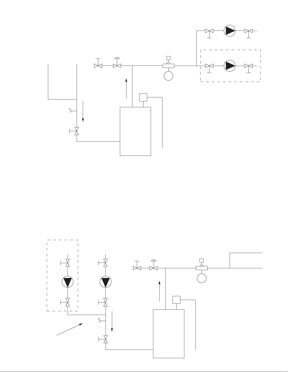
in Figure 1. This is the best pump location for optimum system performance and maintaining positive system pressure.
CAUTION: Do not use flat rubber gaskets. Only use o-ring gaskets provided or leaks may result. Warranty will
be void.
CAUTION: If circulator is installed on the return line, purge valve must be placed on the pump discharge to allow
proper purging of system air. See Figure 2.
“00”-IFC circulator on the supply side of the boiler “pumping away” from the expansion tank as shown
2. Mounting position – Circulator must be mounted with the motor in a horizontal position. It may be mounted vertically
with the motor up, provided that the system cold fill pressure is at least 20 psi (138 kPa).
3. Rotating body – Body has an arrow on the front that indicates direction of flow. To rotate body, remove the four body
bolts, rotate body and replace bolts. Make sure that the junction box is NOT located underneath the circulator. (The
junction box must NOT be located in the 6 o’clock position, as viewed from the motor end.)
4. Electrical connections – Observe all applicable codes when connecting to power supply. The motor is impedance protected, and does not require overload protection. Either colored wire from the capacitor box can be attached to either
colored wire from the power supply. There is no “hot” or “common” wire leading from the capacitor box. Typical installation would be to attach the white wire to the white (common) power supply wire and either the yellow or blue wire
to the black (hot) power supply wire. The pump cannot run backwards.
5. Fill system with tap water – The system must be filled before operating the circulator. The bearings are water lubricated and should not be allowed to operate dry. Filling the system will result in immediate lubrication of the bearings.
It is always good practice to flush a new system of foreign matter before starting the circulator.
6. Circulator operation – Operate the circulator for 5 minutes immediately after flushing the system to purge remaining
air from the bearing chamber. This is especially important when installing the circulator during the off-season.
WARNING: Do not use in swimming pool or spa areas; pump has not been investigated for this
application.
WARNING: In the event the retaining screws have been pulled out of the housing, DO NOT replace
them. Use of any other screw may short out the stator windings, creating a risk of electrical shock.
CAUTION: When installing electrical connections, do not apply mechanical loads to the capacitor box;
otherwise, retaining screws may be pulled out of the housing, making circulator unusable.
CAUTION: Installations at higher elevations over 5000 feet must have higher fill pressure of 20 psi
minimum to prevent pump cavitation and flashing. Premature failure may result. Adjust
expansion tank pressure to equal fill pressure. A larger size expansion tank may be required.
CAUTION: 1. The addition of petroleum based fluids or certain chemical additives to systems
utilizing TACO equipment voids the warranty.
2. Use supply wires suitable for 90°C – ATTENTION: Employer des fils d´alimentation
adequats pour 90°C.
WARNING: To avoid electrical shock, disconnect the power supply to the circulator and the main electrical
unit.
Page 2
BOILER
FF
EXPANSION
TANK
ZONE 1
ADDITIONAL
ZONES
ZONE 1
V2
V2
V3
V3
V1
PV4
FIGURE 1 – PREFERRED
RECOMMENDED PIPING FOR
IFC CIRCULATORS
ON BOILER SUPPLY LINE
P
P
ADDITIONAL
ZONES
BOILER
FF
EXPANSION
TANK
ZONE 1
V1
PV4
FIGURE 2 – ALTERNATE
RECOMMENDED PIPING FOR
IFC CIRCULATORS
ON BOILER RETURN LINE
ZONE 1
V2V2
V3V3
PP
IMPORTANT: NOTE LOCATION
FOR PURGE VALVE. IF IFC IS
INSTALLED ON BOILER RETURN,
PV4 MUST BE ON PUMP DISCHARGE.
ADDITIONAL
ZONES
ADDITIONAL
ZONES
KEY:
VI, V2, V3 = SHUT-OFF ISOLATION
VALVE
P = TACO IFC CIRCULATOR
FF = FAST FILL BOILER FEED VALVE
PV4 = PURGE VALVE
RECOMMENDED PURGING STEPS:
1 .CLOSE V1, PV4, V2
2 . OPEN V3
3 . OPEN FF VALVE
4 .OPEN V2, PV4, TO PURGE ZONE 1
5.CLOSE FF VALVE
CLOSE V2, PV4
6.
REPEAT STEPS 1 TO 6 FOR EACH
7.
ADDITIONAL ZONE
8 . OPEN V1 WHEN ALL ZONES ARE
PURGED
9 . ADJUST SYSTEM TO DESIRED
OPERATING FILL PRESSURE IF
REQUIRED
Page 3
PROPER REMOVAL/REPLACEMENT OF THE INTEGRAL FLOW CHECK (IFC)
Your “00” circulator with an Integral Flow Check (IFC) is designed for easy removal, service and replacement. Please follow these instructions to ensure proper service and operation of the circulator.
REMOVAL:
1. Disconnect power to circulator and related equipment.
2. Shut off water supply. Isolate circulator using service valves or drain system if valves are not available.
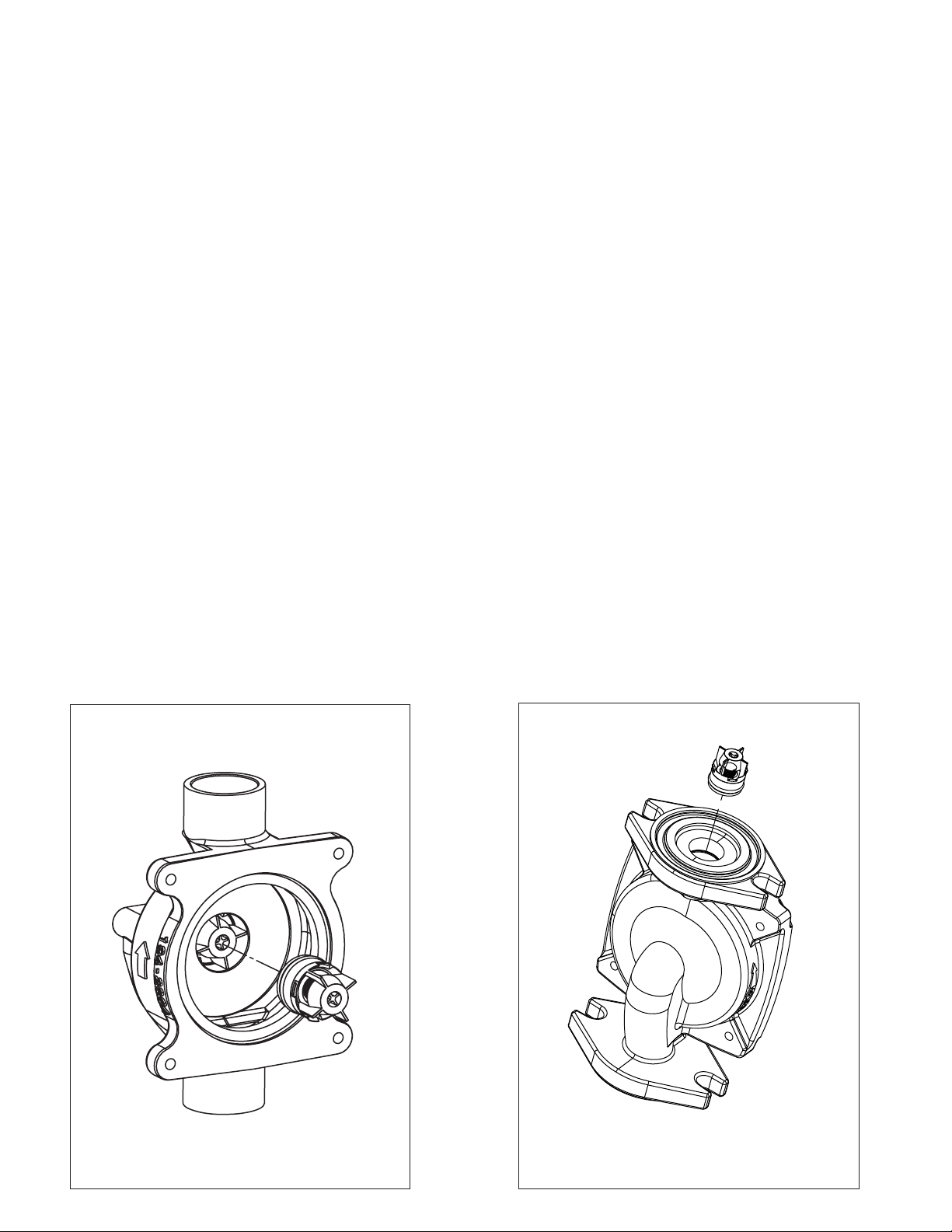
3.a For models listed in Figure 3 below, remove motor housing by loosening four cap screws.
3.b For models listed in Figure 4 below, loosen flange bolts and remove entire circulator from the system to access the IFC.
4. Using needle-nose pliers, carefully grip the IFC’s body and slowly remove the IFC.
REPLACEMENT:
1. Make sure the IFC pocket is clean and free of any debris or particulates.
2. Position IFC into the machined pocket inside the casing as shown in the diagrams below. Firmly press the IFC into
the pocket until it snaps into place.
3. Replace O-ring and reattach motor housing; or reinstall entire circulator with new flange gasket.
4. Open water supply and refill system. Check for any leaks.
5. Reconnect power to circulator and check for proper operation of system.
Figure 3: View of IFC on suction side of “00”
pump casing, with motor housing removed.
Figure 4: View of IFC in discharge
flange of “00” pump casing.
All Sweat Connection Models
All Flanged or Union Connection Models
Page 4

REPLACING MOTOR ASSEMBLY:
1.
Disconnect the electrical supply.
2.
Reduce system pressure to 0 psi and allow system to return to room temperature. Isolate the circulator by closing the
service valves or draining the system.
3. Remove the body bolts and swing motor assembly away from the body.
4.
Install new motor, and reassemble circulator using the new gasket and bolts supplied.
5. Follow the “installation” procedure to start up the circulator
REPLACING CARTRIDGE ASSEMBLY:
1. Disconnect the electrical supply.
2. Reduce system pressure to 0 psi and allow system to return to room temperature. Isolate the circulator by closing the
service valves or draining the system.
3. Remove the body bolts and swing motor assembly away from the body.
4. Pull cartridge out of the motor housing.
5. Install replacement cartridge, making sure that the cover plate is between the cartridge flange and motor.
6. Make sure the replacement cartridge corresponds to the full circulator product number. A complete parts list is available
from your local plumbing supply wholesaler.
7. Reassemble the circulator using the new gasket and bolts supplied.
8. Follow the “Installation” procedure to start up the circulator.
REPLACING CAPACITOR:
1. Replacement capacitor must have same rating as originally furnished.
LIMITED WARRANTY STATEMENT
Taco, Inc. will repair or replace without charge
(at the company’s option) any Taco 00 Series circulator or circulator part which is proven defective under normal use within three (3) years from
the date of manufacture.
In order to obtain service under this warranty, it
esponsibility of the purchaser to promptly
is the r
notify the local Taco stocking distributor or Taco
in writing and promptly deliver the subject product
or part, delivery pr
utor. For assistance on warranty returns, the
purchaser may either contact the local Taco
stocking distributor or Taco. If the subject product or part contains no defect as covered in this
warranty, the purchaser will be billed for parts
and labor charges in effect at time of factory
examination and repair.
Any Taco product or part not installed or operated
in conformity with Taco instructions or which has
been subject to misuse, misapplication, the
epaid, to the stocking distrib-
addition of petroleum-based fluids or certain
chemical additives to the systems, or other
abuse, will not be covered by this warranty.
If in doubt as to whether a particular substance
is suitable for use with a Taco product or part, or
for any application restrictions, consult the
applicable T
Taco at (401-942-8000).
Taco reserves the right to provide replacement
products and parts which are substantially similar
in design and functionally equivalent to the
defective product or part. Taco reserves the right
to make changes in details of design, construction,
without notification.
TACO OFFERS THIS WARRANTY IN LIEU OF
ALL OTHER EXPRESS W
WARRANTY IMPLIED BY LAW INCLUDING
WARRANTIES OF MERCHANTABILITY OR
FITNESS IS IN EFFECT ONLY FOR THE DURA-
aco instruction sheets or contact
or arrangement of materials of its products
ARRANTIES. ANY
TION OF THE EXPRESS WARRANTY SET
FORTH IN THE FIRST PARAGRAPH ABOVE.
THE ABOVE W
ALL OTHER WARRANTIES, EXPRESS OR
STATUTORY, OR ANY OTHER WARRANTY
OBLIGATION ON THE PART OF TACO.
ACO WILL NOT BE LIABLE FOR ANY SPE-
T
CIAL, INCIDENTAL, INDIRECT OR CONSEQUENTIAL DAMAGES RESULTING FROM THE
USE OF ITS PRODUCTS OR ANY INCIDENTAL
COSTS OF REMOVING OR REPLACING
DEFECTIVE PRODUCTS.
This warranty gives the purchaser specific
rights, and the purchaser may have other rights
which vary from state to state. Some states do
not allow limitations on how long an implied warranty lasts or on the exclusion of incidental or
consequential damages, so these limitations or
exclusions may not apply to you.
ARRANTIES ARE IN LIEU OF
 Loading...