

Page 1
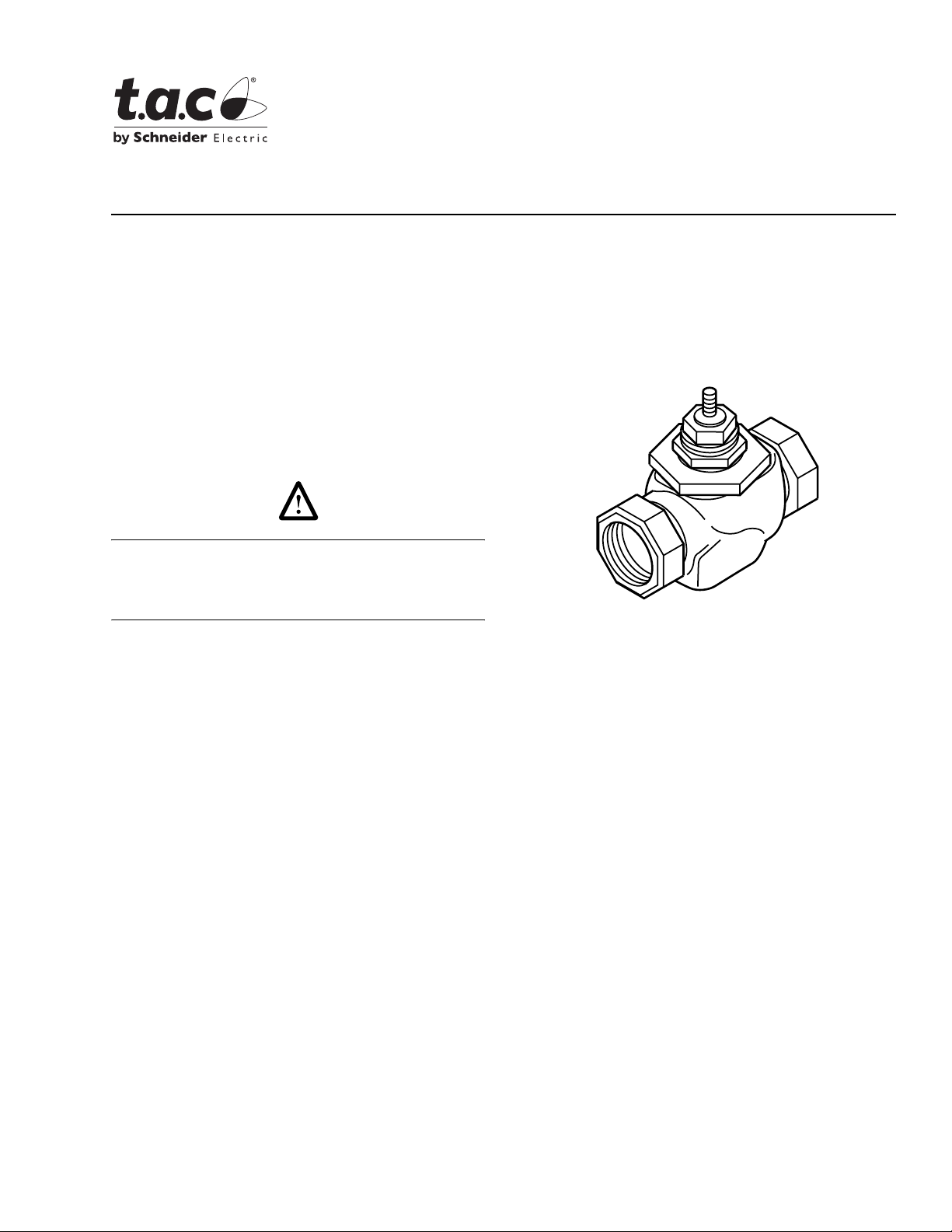
Application
VB-7213 series single seat, stem up open, two-way
valves control water from 20 to 281°F (-7 to 138°C) or
steam to 281°F (138°C) maximum in heating or air
conditioning systems. They are used for two-position or
proportional control applications. Valve assemblies
require an actuator and a valve linkage. A large
selection of factory assembled combinations is
available. Consult the TAC Valve Products Catalog,
F-27384.
VB-7213 Series
1/2" to 2" Screwed NPT
Stem Up Open, Two-Way Valves
General Instructions
Danger:
The VB-7213 series valve packings are not rated for
combustible gas applications, and if used in these
applications, gas leaks and explosions could result.
Do not use for combustible gas applications.
Features
• Valve sizes 1/2" to 2"
• 250 psig pressure rating per ANSI Standards
(B16.15–1985) for screwed cast bronze bodies
• Spring-loaded TFE packing
• American Standard Taper Pipe Thread (NPT)
connections
Applicable Literature
• TAC Valve Products Catalog, F-27384
• TAC Cross-Reference Guide, F-23638
• TAC Reference Manual, F-21683
• TAC Application Manual, F-21335
• Control Valve Sizing, F-13755
• Valve Selection Chart for Steam, F-11366
• Valve Selection Chart for Water, F-11080
• EN-205 Water System Guidelines, F-26080
Printed in U.S.A. 8-08 © Copyright 2008 TAC All Rights Reserved. F-26075-2
Page 2
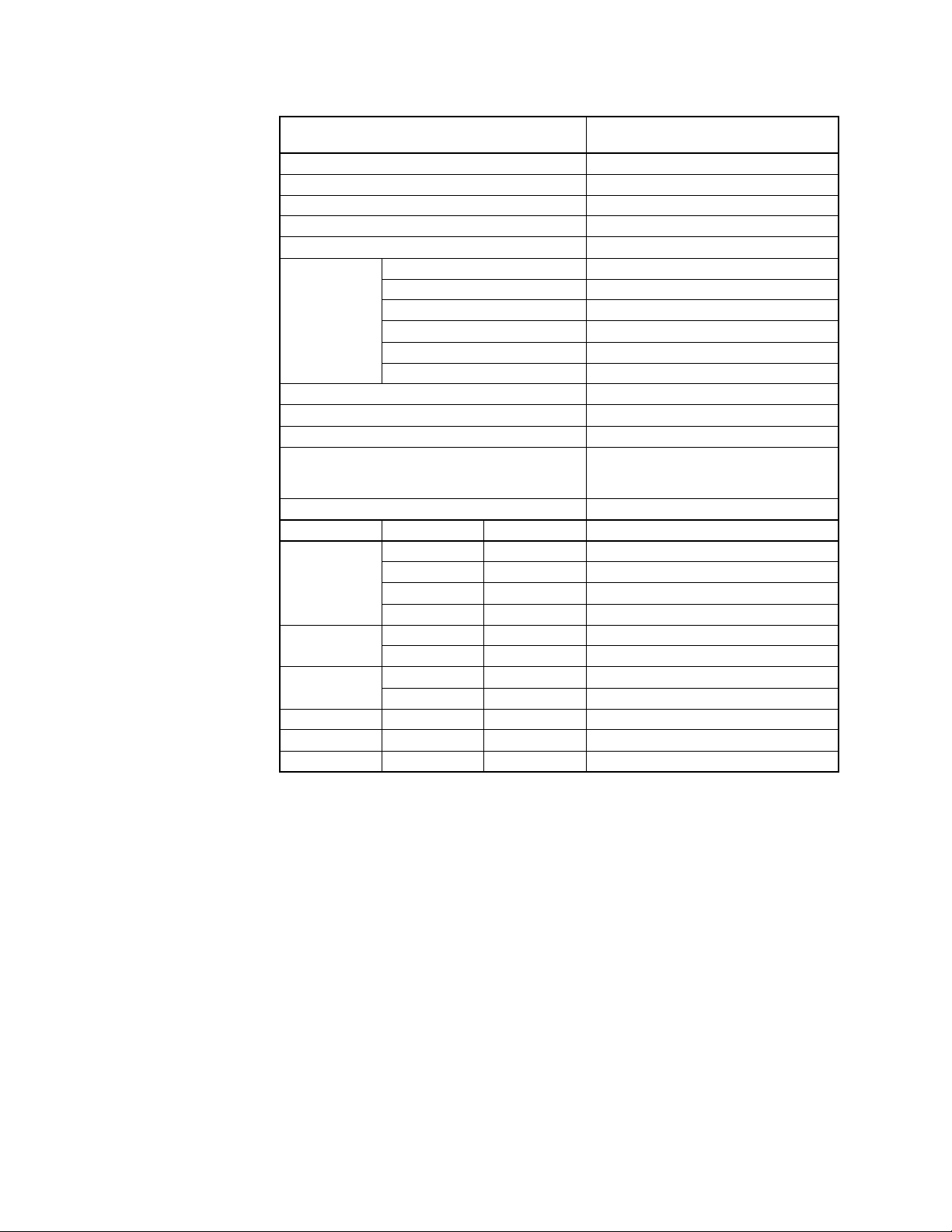
SPECIFICATIONS
Table-1 Specifications/Models.
Specifications
Valve Body Serie s
VB-7213-0-4-P
Service Chilled or Hot Water and Steam
Flow Characteristics (Figure-1) Equal Percentage
Action Stem Up Open
Sizes 1/2" to 2"
Type of End Fitting NPT
Body Bronze
Seat Bronze
Valve
Materials
Stem S t ai nless Ste el
Plug Brass
Packing Spring-load ed TFE
Disc EPDM
ANSI Pressure Class (Figure-2) 250 (up to 400 psig below 150°F)
a
Maximum Inlet Pressure, Steam 35 psig (241 kPa)
Allowable Control Media Temperature 20 to 281°F (-7 t o 138°C)
Allowable Differential Pressure for Water
b
35 psi (241 kPa) Max. for Normal Life
(refer to “Cavitation Limita tions on Valve
Pressure Drop” on pa ge 7)
Allowable Dif ferential Pressure for S team
Valve Size C
Rating kvs Rating
v
b
20 psi (138 kPa)
c
Complete Valve Body Part Number
0.4 0.3 VB-7213-0-4-1
1/2"
1.3 1.1 VB-7213-0-4-2
2.2 1.9 VB-7213-0-4-3
4.4 3.8 VB-7213-0-4-4
3/4"
1"
5.5 4.8 VB-7213-0-4-5
7.5 6.5 VB-7213-0-4-6
10 8.7 VB-7213-0-4-7
14 12 VB-7213-0-4-8
1-1/4" 20 17 VB-7213-0-4-9
1-1/2" 28 24 VB-7213-0-4-10
2" 40 35 VB-7213-0-4-11
a
Do not apply above pressure rating to piping system.
b
Maximum recommended differential pressure in open position. Do not exceed recommended differential
pressure (pressure drop) or integrity of parts may be affected. Exceeding maximum recommended differential
pressure voids product warranty.
c
kvs = m3/h (ΔP = 100 kPa) Cv = kvs x 1.156
Close-off Pressure Rating
The close-off pressure rating is dependent on the size of the valve, valve linkage, and
actuator. Consult the TAC Valve Prodcuts Catalog, F-27384, for close- of f ratings.
2 © Copyright 2008 TAC All Rights Reserved. F-26075-2
Page 3

Normal Position of Valve Assembly
For a valve assembly (valve, link age, and actuator) to have a normal (spring ret urn) position,
the actuator must be of the spring ret urn type. See Table-2 for spri ng return posit ion of valve
assemblies.
Table-2 Required Compatible Actuators/Linkages.
Actuator Seri es Requi red Valve Linkage Normal Position
MA-318, MA-418, MA-419 AV-391 N.O. or N.C.
MA-5210, MA-5211, MA-5213 AV-7600
a
MC-351, MC-431, MC-4311, MC5-4311 AV-393 None
MF-5413, MF-5513 AV-7600
MF-22203, MF-22303, MF-22323
MF-63103, MF-63123
Included w/Actuator None
a
MK-2690 AV-7400
MK-6601, MK-6611, MK-6621 AV-430
MM-400, MMR-400
MM-500, MMR-500 N.O. or N.C.
MP-361, MP-367, MP-465, MP5 -4651
MP-371, MP-377, MP-475, MP5-4751 Normally Open
MP-381, MP-382, MP-387, MP-485,
MP-486, MP-4851, MP5-4851
MP-5210, MP-5211, MP-5213 AV-7600
AV-630 or
AV-630-010
AV-391
AV-393 None
a
MP-5410, MP-5411, MP-5413
MP-5513
MPR-5610, MPR-56 11, MPR-5 613
AV-7600 & AV-601
MPR-5713
MS-22353 Included w/Actuator None
a
High ambient temperatures with high media temperatures in the valve may require the use of AV-601 in addition
to AV-7600. See General Instructions for AV-7600 (F-26235) and AV-601 (F-19069) for details.
Normally Open
Normally Open
Normally OpenMK-4601, MK-4611, MK-4621 AV-401
None
Normally Closed
Normally Open
Flow Characteristics
All valves have modifi ed equal perc entage flow char acterist ics. That is, for equa l increment s
of valve stem str oke, t he change in f low rat e with res pect to val ve str oke may be ex pressed
as a cons tant p ercent of t he flow rat e at the time o f the cha nge. The cha nge o f fl ow rat e wit h
respect to val ve str oke is relativel y small when the valve plug is near the valve seat and
relatively high when the valve plug is nearly wide open. See Figure-1 for typical modified
equal percentage flow characterist ics of VB-7213 series val ve bodies.
100%
90%
80%
70%
60%
50%
Flow
40%
30%
20%
10%
0%
0%
10%
20%
30%
40%
50%
60%
70%
80%
90%
100%
Closed
Stroke
Open
Figure-1 Typical Modified Equal Percentage Flow Characterist ics.
F-26075-2 © Copyright 2008 TAC All Rights Reserved. 3
Page 4
Rangeability
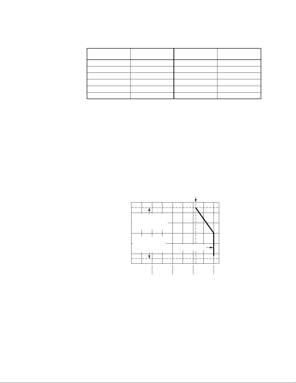
Rangeability is the ratio of rated flow to the minimum controllable flow t hrough a valve.
Table-3 lists the rangeability for V B-7213 series valves.
Table-3 Rangeability.
Valve Bo dy
Part Number
VB-7213-0-4-1 5:1 VB-7213-0-4-7 60:1
VB-7213-0-4-2 15:1 VB-7213-0-4-8 75:1
VB-7213-0-4-3 25:1 VB-7213-0-4-9 75:1
VB-7213-0-4-4 40:1 VB-7213-0-4-10 75:1
VB-7213-0-4-5 50:1 VB-7213-0-4-11 75:1
VB-7213-0-4-6 60:1
Nominal
Rangeability
Valve Body
Part Number
Nominal
Rangeability
Temperature/Pressure Ratings
See Figure-2 for temperature and pressure ratings. Consult the appropriate valve linkage
general inst ruction sheet for the eff ect of valve body ambient temperatures on specif ic
actuators. Ratings conform with published values and disclaimer.
VB-7213-0-4-P (Screw ed Cast Bronze Body)
Standards:
321 psig at 281°F
Materials:
Pressure to ANSI B16.15 Class 250 with 400 psig up to 150°F decre asing to
Bronze, ASTM B584
321 psig
(2218 kPa)
300 (149)
250 (121)
200 (93)
150 (65)
100 (38)
Temperature — °F (°C)
50 (10)
Maximum Media
Temperature
281°F (138°C)
Minimum Fluid
Temperature
20°F (-7°C)
50
(345)
Figure-2 Temperature and Pre ssure Ratings
for VB-7213 Series Valve Bodies.
150
(1034)
100
(689)
200
(1379)
Pressure — psig (kPa)
VB-7213-0-4-P
250
(1724)
(2458)
300
(2068)
350
400
(2758)
4 © Copyright 2008 TAC All Rights Reserved. F-26075-2
Page 5
VALVE SIZING AND SELECTION
Water Two-position
Two-position control valves are nor ma ll y selected “line si ze” to keep pressure drop at a
minimum. If it is desi rable to reduce the val ve below line size, then 10% of “avai lable
pressure” (that is, the pump pres sure differe ntial avai lable between suppl y and return mains
with design flow at the valve location) is normally used to select the valve.
Proportional
Proportiona l contr ol valv es are us ually s elected t o take a pres sure drop equal t o at l east 5 0%
of the “available pressure.” As “available pressure” is often difficult to calculate, the normal
procedure is to select the valve using a pressure drop at least equal to the dro p in th e coil
or other loa d being control led (except where small booster pumps ar e used) wit h a minimum
recommended pressure drop of 5 psi (34 kPa). When the design temperature drop is less
than 60°F (33°C) for conventi onal heat in g systems, higher pr essu re drops acr oss the val ve
are needed for good res ults (Table-4).
Table-4 Conventional Heating System.
Design Temperature
Load Drop °F (°C)
60 (33) or More 50% 1 x Load Drop
40 (22) 66% 2 x Load Drop
20 (11) 75% 3 x Load Drop
a
Recommended minimum pressure drop = 5 psi (34 kPa).
Recommende d Pres su re Drop
(% of Availabl e Pressure)
a
Multiplier on
Load Drop
Secondary Circuits with Small Booster Pumps: 50% of available pressure difference
(equal to the drop through load, or 50% of booster pump head).
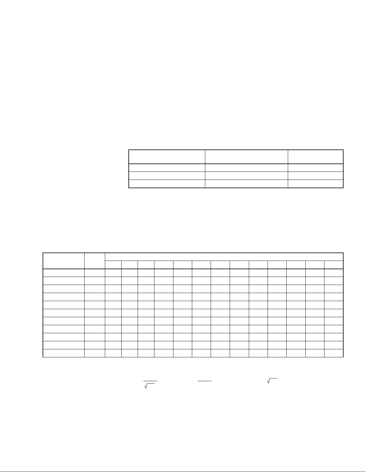
Water Capacity
See Table-5 for water capacity of VB-7213 series val ves.
Table-5 Water Capacity in Gallons Per Minute for VB-7213 Series.
Valve Body
Part Number
VB-7213-0-4-1 0.4 0.40 0.57 0.69 0.80 0.89 0.98 1.06 1.13 1.20 1.26 1.55 1.79 2.37
VB-7213-0-4-2 1.3 1.30 1.84 2.3 2.6 2.9 3.2 3.4 3.7 3.9 4.1 5.0 5.8 7.7
VB-7213-0-4-3 2.22.23.13.84.44.95.45.86.26.67.08.59.8 13
VB-7213-0-4-4 4.4 4.4 6.2 7.6 8.8 9.8 11 12 12 13 14 17 20 26
VB-7213-0-4-5 5.5 5.5 7.8 9.5 11 12 13 15 16 17 17 21 25 33
VB-7213-0-4-6 7.5 7.5 11 13 15 17 18 20 21 23 24 29 34 44
VB-7213-0-4-7 10 10 14 17 20 22 24 26 28 30 32 39 45 59
VB-7213-0-4-8 14 14 20 24 28 31 34 37 40 42 44 54 63 83
VB-7213-0-4-9 20 20 28 35 40 45 49 53 57 60 63 77 89 118
VB-7213-0-4-10 28 28 40 49 56 63 69 74 79 84 89 108 125 166
VB-7213-0-4-11 40 40 57 69 80 89 98 106 113 120 126 155 179 237
C
v
Rating
12345678910152035
Differential Pressure (
ΔP in psi)
Cv Equation
2
Cv=
GPM
ΔP
ΔP=
GPM
()
C
v
GPM = Cv ΔP
Where:
Cv= Coefficient of flow
GPM = U.S. gallons per minute (60°F, 15.6°C)
ΔP = Differential pressure in psi (pressure drop)
F-26075-2 © Copyright 2008 TAC All Rights Reserved. 5
Page 6
Steam Two-position
Two-position z one valves and direc t radiati on v alves are normal ly si zed using a mi nimum of
10% of inlet pressure (psig).
Proportional
Proportiona l control valves are norm ally sized using:
• For low pressure (15 psig or less), use ΔP of 80% of gauge inlet pressure.
• For steam pressur es greater than 15 psig, use ΔP of 42% of absolute (gauge plus 14.7)
inlet pres su r e .
• When the C
steam valves using a pressure drop greate r than 42% of the absolute inlet pressure.
Steam Capacity
See Table-6 for steam capacity of VB-7213 series valves.
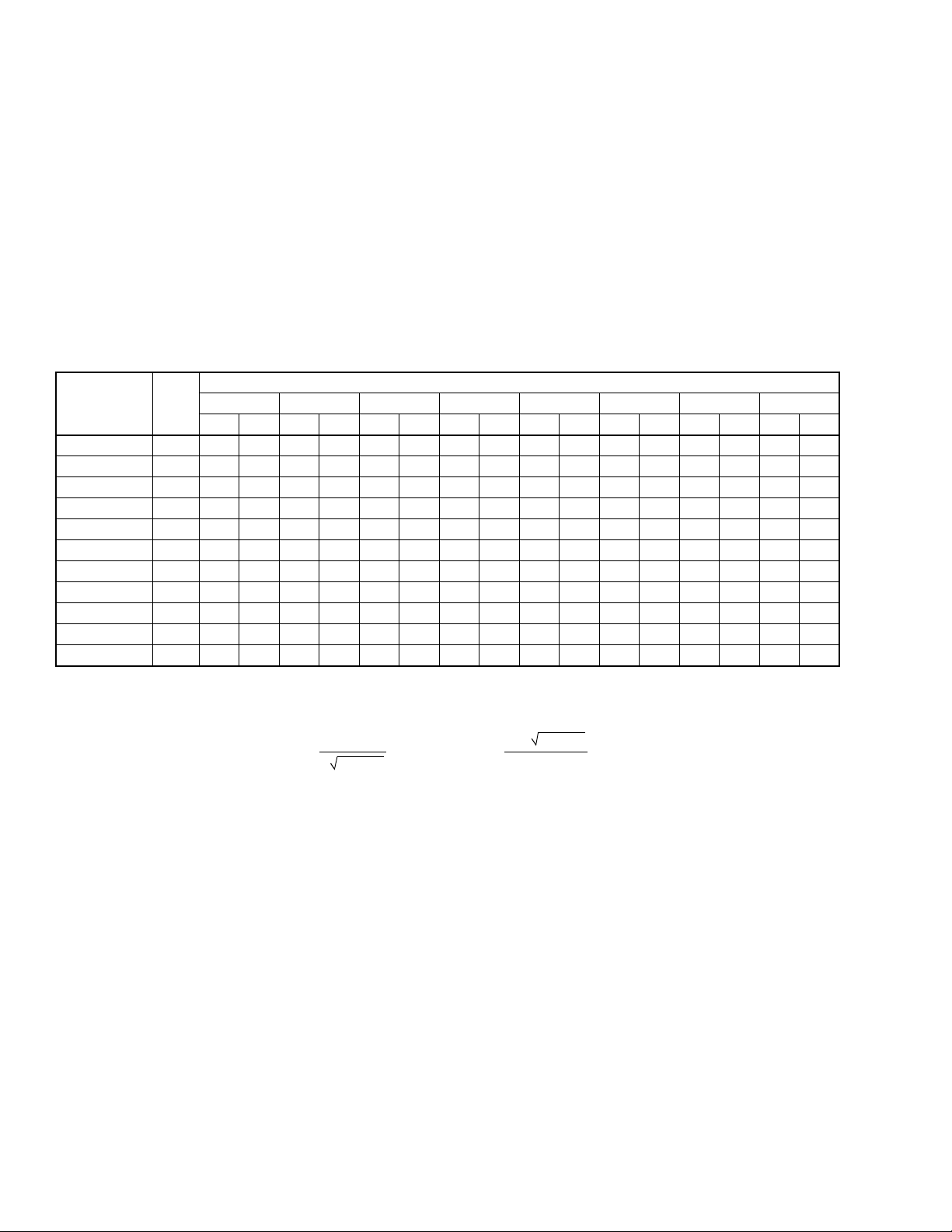
Table-6 Steam Capacity in Pounds Per Hour for VB-7213 Series.
Valve Body
Part Number
VB-7213-0-4-1 0.4 2.2 5.9 3.7 9.5 5.8 13.9 7.8 17.5 9.7 20.4 11.6 23.4 13.4 26.3 15.3 29.2
VB-7213-0-4-2 1.3 7.1 19.2 12.1 30.9 19.0 45.1 25.4 56.8 31.5 66.4 37.6 75.9 43.6 85.5 49.6 95.1
VB-7213-0-4-3 2.2 12.0 32.4 20.4 52.3 32.1 76.3 42.9 96.2 53.4 112 63.6 129 73.8 145 83.9 161
VB-7213-0-4-4 4.4 24.0 64.9 40.9 105 64.3 153 85.9 192 107 225 127 257 148 289 168 322
VB-7213-0-4-5 5.5 30.0 81.1 51.1 131 80.3 191 107 240 133 281 159 321 185 362 210 402
VB-7213-0-4-6 7.5 40.9 111 69.7 178 110 260 146 328 182 383 217 438 252 493 286 548
VB-7213-0-4-7 10 54.5 147 93 238 146 347 195 437 243 511 289 584 336 658 381 731
VB-7213-0-4-8 14 76.3 206 130 333 204 485 273 612 340 715 405 818 470 921 534 1024
VB-7213-0-4-9 20 109 295 186 475 292 694 390 874 485 1021 579 1168 671 1315 763 1462
VB-7213-0-4-10 28 153 413 260 666 409 971 546 1224 679 1430 810 1636 939 1841 1068 2047
VB-7213-0-4-11 40 218 590 372 951 584 1387 780 1749 970 2043 1157 2337 1342 2631 1526 2925
a
Values are for saturated steam (K = 1). Left column under each inlet pressure is for two-position control, and right column is for proportional control.
C
v
Rating
2 psig Inlet 5 psig Inlet 10 psig Inlet 15 psig Inlet 20 psig Inlet 25 psig Inlet 30 psig Inlet 35 psig Inlet
0.2 1.6 0.5 4 1 8 1.5 12 2 14 2.5 16 3 18 3.5 20
required is between two valve sizes, select the larger size. Do not size
v
Differential Pressure (
ΔP in psi)
a
Cv Equation
Cv=
QK
ΔP • P23
Where:
Cv= Coefficient of flow
Q = Lbs. per hour of steam
Q=
ΔP • P23C
v
K
ΔP = Di fferential pressure in psi (pressure drop)
P2 = Outlet pressure in psia (absolute) (P2 = Inlet pressure + 14.7 –
K = 1 + (0.0007 x °F superheat) (K = 1 for saturated steam)
ΔP)
6 © Copyright 2008 TAC All Rights Reserved. F-26075-2
Page 7

Cavitat ion Limitati ons
on Valve Pressure
Drop
A valve selected with too hi gh a pressure drop can cause erosi on of discs and/or wire
drawing of the seat. I n addition, cavita ti on can cause noise, damage to the valve trim (and
possibly the body), and choke the flow through the valve.
Do not exceed the maximum differential pressure (pressure drop) for the valve selecte d.
The following formula can be used on higher temperature water systems, where cavitation
could be a problem, to estimate the maximum allowable pressure drop across the valve:
Pm = 0.5 (P
– Pv)
1
Where:
Pm = Maximum allowable pressure drop (psi)
P
= Absolu te inlet press u re (psia )
1
Pv = Absolute vapor pressure (psia) (r efer to Table-6 or Table-7)
Note:
Add 14.7 psi to gauge supply pressure to obtain absol ute pressure value.
For example, if a valve is controlling 200°F water at an inlet pressure of 18 psig, the
maximum pressure drop allowable would be:
Pm = 0.5 [(18 + 14.7) – 11.53] = 10.6 psi
(Vapor pressur e of 200°F water is 11.53 psia.)
If the pressure drop for this valve is less t han 10.6 psi, cavitation should not be a problem.
Systems where cavit ation is shown to be a problem can sometimes be redesigned to provide
lower inlet velo cities. Valves having harder seat material s should be furnished if inl et
velocities cannot be lowered.
Table-7 Vapor Pressure of Water Table.
Additional Valve
Sizing Information
Water
Temp.
(°F)
40 0.12 90 0.70 140 2.89 190 9.34
50 0.18 100 0.95 150 3.72 200 11.53
60 0.26 110 1.28 160 4.74 210 14.12
70 0.36 120 1.69 170 5.99 220 17.19
80 0.51 130 2.22 180 7.51 230 20.78
Vapor
Pressure
(psia)
Water
Temp.
(°F)
Vapor
Pressure
(psia)
Water
Temp.
(°F)
Vapor
Pressure
(psia)
Water
Temp.
(°F)
For additiona l val ve sizing informat ion, see:
• CA-28 Control Valve Sizing, F-13755
• Valve Selection Chart Water, F-11080
• Valve Selection Char t Ste am, F-11366
• Valve Sizing Slide Rule, TOOL-150
Vapor
Pressure
(psia)
F-26075-2 © Copyright 2008 TAC All Rights Reserved. 7
Page 8
INSTALLATION
Inspection Inspect t he package for damage. If damaged, notify the appropriate carrier immediately.
If undamaged, open the package and inspect the device for obvious damage. Return
damaged products.
Requirements • Tools (not provided): Pipe wrenches
• Training: Installer must be a qualifi ed, experienced techni cian
• Appropriate accessories
Caution:
• Install the valve with the flow in the direction of the flow arrow (“A” port is the inlet and
“AB” port is the outlet).
• Do not exceed the ratings of the device.
• Avoid locations where excessive moistur e, corrosive fumes, or vibration are present.
Mounting 1. The valve should be mounted in a weather-protected area in a location that is within the
ambient limits of the actuator. When selecting a location, allow sufficient room for valve
linkage, actuator, and other accessories and for service of the product.
2. The preferred mounting position for the valve is with the valve stem ver ti cal above the
valve body. Avoid mounting the valve so that the valve stem is below horizontal.
3. On steam applications where the ambient temperat ure approaches the limit of the
actuator, the valve stem should be mounted 45° from vertical.
4. The valves must be piped with the “A” port as the inlet and the “AB” port as the outlet.
Screwed Valve Bodies
The VB-7213-0-4 ser ies screwed valve bodies conform to American Standard Taper Pipe
Threa ds (NP T ).
1. Apply pipe dope sparingly to all but the last two threads of a properly threaded, reamed,
and cleaned pipe. Make sure that pipe chips, scale, etc. do not get into the pipe since this
material may lodge in the valve seat and prevent proper closing and opening of the valve.
2. Start the joint by hand screwing the pipe into the valve. If the thread enga gem ent feels
“right,” turn the pipe by hand as far as it will go.
3. Use a pipe wrench to fully tighten the valve to the pipe. Do not over tighten or strip
threads. See Table-8 and Figure-3 for the normal engagement length of the threads.
Figure-4 shows a means of tightening the pipe so that th e valve is not twisted or
crushed.
Table-8 Normal Thread Engagement Between Male Pipe Thread and Valve Body.
Valve Size Inche s
(NPT)
1/2" 1/2" 1-1/4" 11/16"
3/4" 9/16" 1-1/2" 11/16"
1" 11/16" 2" 3/4"
Normal Engagement
Valve Size Inche s
(NPT)
Normal Engagement
8 © Copyright 2008 TAC All Rights Reserved. F-26075-2
Page 9
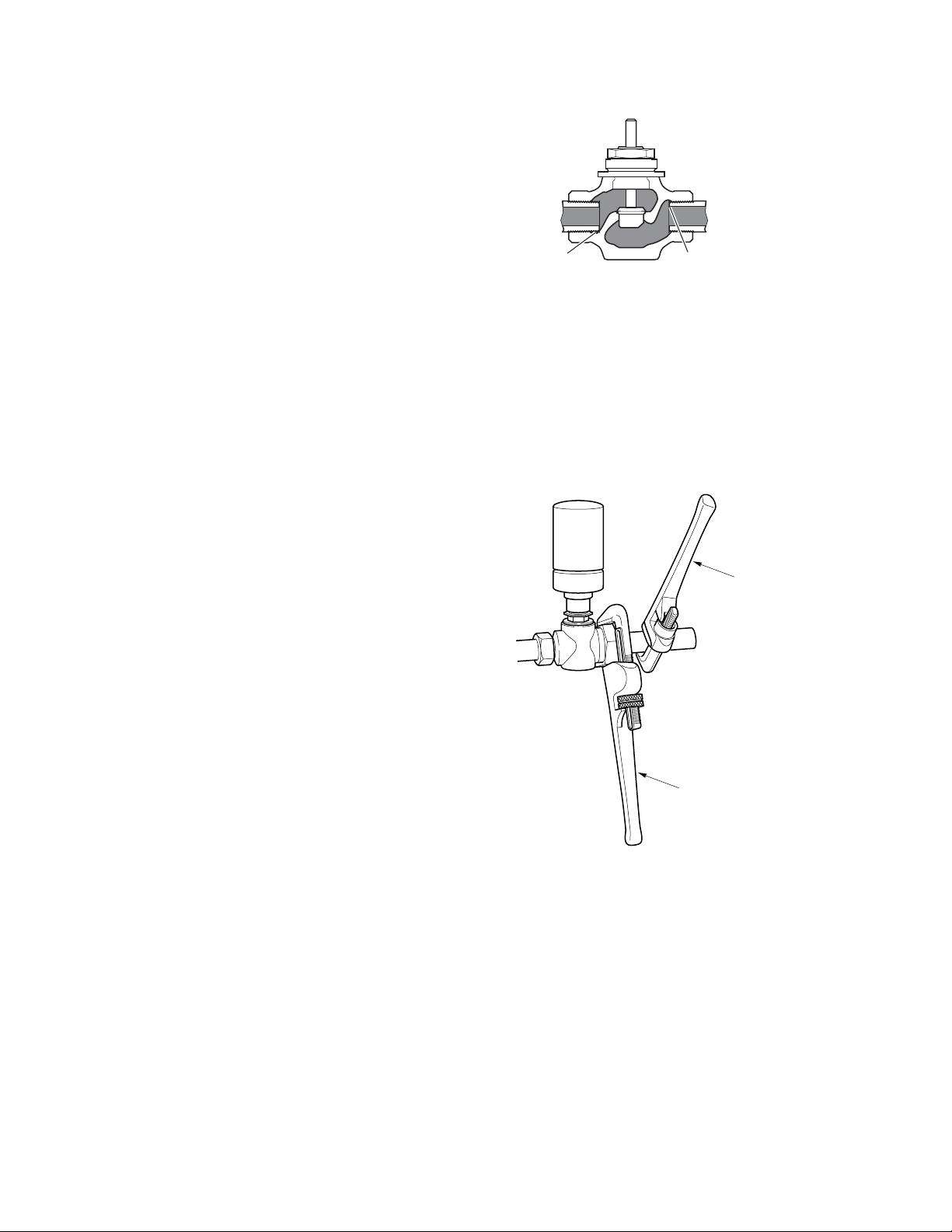
Pipe threads too long.
Pipe interferes with seat.
Wrong
Right
Figure-3 Nor mal Thread Engagement.
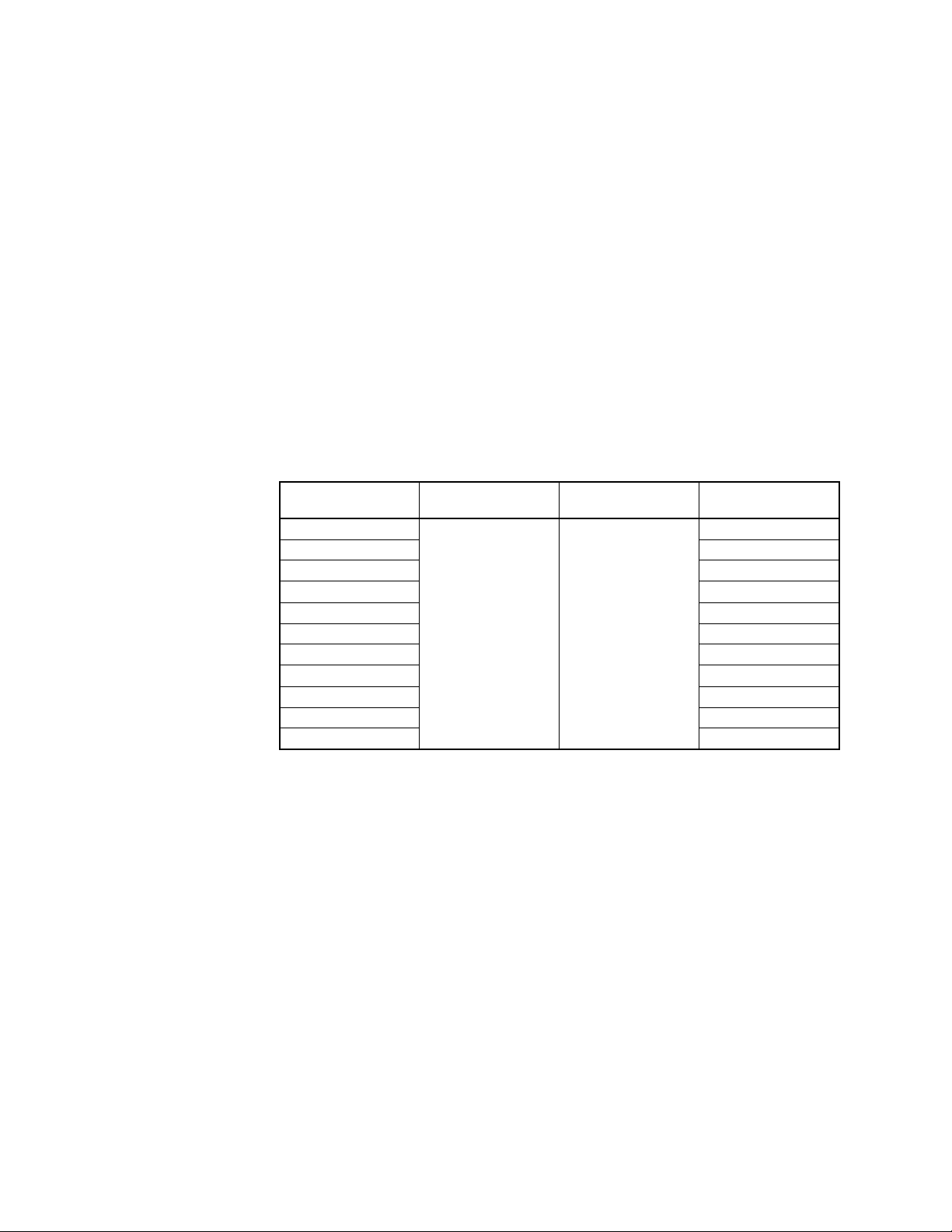
Valve
Assembly
Tighten pipe using
this pipe wrench.
Use pipe wrench to
prevent valve from turning.
Figure-4 Installation of Screwed End Valves.
F-26075-2 © Copyright 2008 TAC All Rights Reserved. 9
Page 10
CHECKOUT
MAINTENANCE &
FIELD REPAIR
1. Make sure the valve stem operates smoothly before installing the valve linkage and the
actuator.
2. If the stem does not operat e sm oothly, it may indicate t hat the valve was twisted or
crushed during installation or that the stem was bent by rough handling. These
conditions may require that the valve be replaced.
3. After the pipi ng is under pressure, check the valve body and the connections for l eaks.
4. After the valve linkage and the actuator are installed, check their operation.
a. Power the actuator and run the valve to the stem down position. Make sure the
linkage and valve stem move freely. At the stem down position, the valve should
shut off tightly .
b. For spring return actuators, allow the actuator to spring return to the stem up
position. Again, the valve stem and linkage should operate smoothly. At the stem
up position, the valve should be in its full open position.
Regular maint enance of the t otal sys tem is re commended t o assure su stained p erforma nce.
See for maintenance kit part numbers.
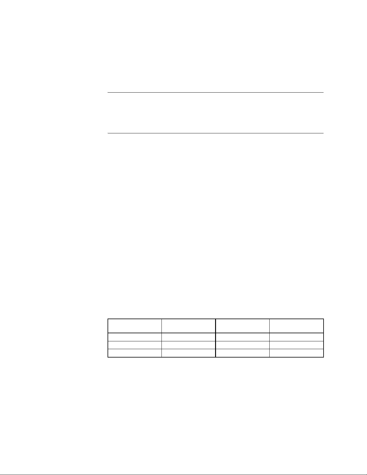
Table-9 Maintenance Kits for VB-7213 Valves
Water System
Maintenance
Valve Bo dy
Part Number
VB-7213-0-4-1
VB-7213-0-4-2 RYB-721-2
VB-7213-0-4-3 RYB-721-3
VB-7213-0-4-4 RYB-721-4
VB-7213-0-4-5 RYB-721-5
VB-7213-0-4-6 RYB-721-6
VB-7213-0-4-7 RYB-721-7
VB-7213-0-4-8 RYB-721-8
VB-7213-0-4-9 RYB-721-9
VB-7213-0-4-10 RYB-721-10
VB-7213-0-4-11 RYB-721-11
a
Kit includes replacement packing and stem & plug assembly.
Replacement
Packing Assembly
YBA-622-1 TOOL-20-1
Packing Wrench Valve Repair Kit
a
RYB-721-1
All heating and cooli ng systems are suscept ible to valve and system problems caused by
improper water treatment a nd system stor age procedure s. These guide lines are provi ded to
help avoid valve and water system problems resulting from improperly treated water or
storage pro cedures in cooli ng and ho t wa ter sy stem s, and to obtain maxim um lif e fro m TAC
valves.
Durability of valve stems and packings is dependent on maintaining non-damaging water
conditions . In adequate water treatment or fi ltration, not in acc ordance with chemical
supplier/ASHRAE ha ndbook r ecommend ations , can re sult in c orrosi on, s cale, and ab rasive
particle for mation. Scale and pa rt icula tes can r esult i n stem and pac ki ng scrat ches and can
adversely aff ect packing life and ot her parts of the hydronic system.
To maintain non-damaging conditions, follow these guidelines:
• Clean the syst em prior to star t up. Use a nitr ite or mo lybdat e-based t reatment pr ogram.
• Use filtration equipment where needed.
• Properly store off -line systems and monitor water treat ment result s using corrosion t est
coupons.
• Follow the advice of a wate r tr eatment professional .
• Consult EN-205, Water System Guidelines Engineering Information, F-26080, for
further detail s.
10 © Copyright 2008 TAC All Rights Reserved. F-26075-2
Page 11

DIMENSIONAL DATA
Table-10 Di me nsions for VB-7213 Series Valve (Figur e-5).
Part
Number
VB-7213-0-4-1
VB-7213-0-4-2
VB-7213-0-4-3
VB-7213-0-4-4
VB-7213-0-4-5
VB-7213-0-4-6
VB-7213-0-4-7
VB-7213-0-4-8
VB-7213-0-4-9 1-1/4" 1-3/8 (35)
VB-7213-0-4-10 1-1/2" 5-3/8 (137) 1-1/2 (38) 2-7/16 (57)
VB-7213-0-4-11 2" 6-1/8 (156) 1-9/16 (40) 2-3/4 (70)
a
Stroke for rated flow. Add up to 1/16 inch (1.6 mm) for disc seating and compression.
Valve
Size
1/2" 3-1/16 (78)
3/4" 3-5/8 (92)
1"
AB C
4-5/8 ( 11 8)
Dimensio ns in Inches (mm )
1-1/16 (27) 1-11/16 (43)
1-1/8 (29)
2-3/8 (60)
E
D
D
(Stem Down)
3/4 (19) 7/16 (11)
C
a
E
(Stroke)
B
A
Figure-5 Typical of VB-7213-0-4-P Valve Bodies.
F-26075-2 © Copyright 2008 TAC All Rights Reserved. 11
Page 12

Copyright 2008, TAC
All brand names, trademarks and registered
trademarks are the property of their respective
owners. Information contained within this
document is subject to change without notice.
F-26075-2
TAC
1354 Clifford Avenue
P.O. Box 2940
Loves Park, IL 61132-2940
www.tac.com
 Loading...