

Page 1
APPLICATION
For proportional temperature control of pneumatic valves and
actuators to maintain air or liquid tempe rat ures in duct,
plenum chambers , li quid lines, tanks , et c. May also be used
as a low limit thermostat.
SPECIFICATIONS
Thermostat: Proportiona l two pipe type. Thermostats are
ambient compens ated.
Sens ing Ele m ent: Remote liquid-fi lled copper.
Control Dial Range: -20 to 240°F ( -29 t o 115°C). Shipped
as -20 to 120°F, reverse side of dial 100 to 240°F.
Throttling Range: Adjustab le 3 t o 35°F /10 psi (2 to 19°C/69
kPa) change in output , factory set at 5°F (3°C).
Output Air Signal: 0.5 psig (3.4 kPa) to suppl y a ir pr essure
-0.5 (-3. 4 kP a ).
Action: See Table 1.
Ambient Limits:
Shipping, -40 to 150°F ( -40 t o 65°C). 0 to 98% R.H.,
non-condensing.
Case Operating, 40 to 150°F (4 to 65°C). 10 to 98%
R.H., non-condensing.
Bulb, 310°F (154°C) maximum.
Supply Air Pressure: Clean, oil free, dry ai r required
(reference EN-123).
Nominal, 20 psig (138 kPa).
Minimum, 15 psig (103 kPa).
Maximum, 30 psig (207 kPa).
Air Connections: 1/8" FNPT for main, branches and
AL-362 gauges (not i ncluded).
Air Consumption for Sizing Air compres sor: 0.008 scfm
(3.8 ml/s).
Air Capacity for Sizing Air Mains: 16 scim (4.4 ml/s).
Mounting: Upright position on a wall or vert ical flat surface.
Bulb Dimensions: See T able 1.
Capillary Length: 6’ (1.8 m).
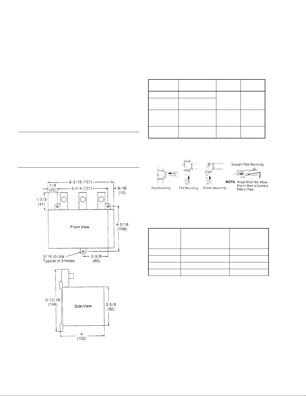
Case Dimensions: 5-13/16" high x 6- 3/16" wide x 4" deep
(148 mm x 157 mm x 102 mm).
ACCESSORIES
AL-362 Stem mounted back connected 0-30 psi gauge
AT-201 3/8" x 9-1/2" with 3/4" MNPT copper bulb well
requires AT-209
AT-203 3/8" x 9-1/2" with 3/4" MNPT stainless steel bulb
well requires AT-209
AT-206 3/8" x 4-1/2" with 1/2" MNPT copper bulb well
AT-208 Duct mo un ting kit
AT-209 Liquid line or tank mounting kit
AT-211 Bulb shie ld
AT-539 Pilot pressure kit
TOOL-95 Pneumatic calibration tool kit (required for use
as low limit thermostat)
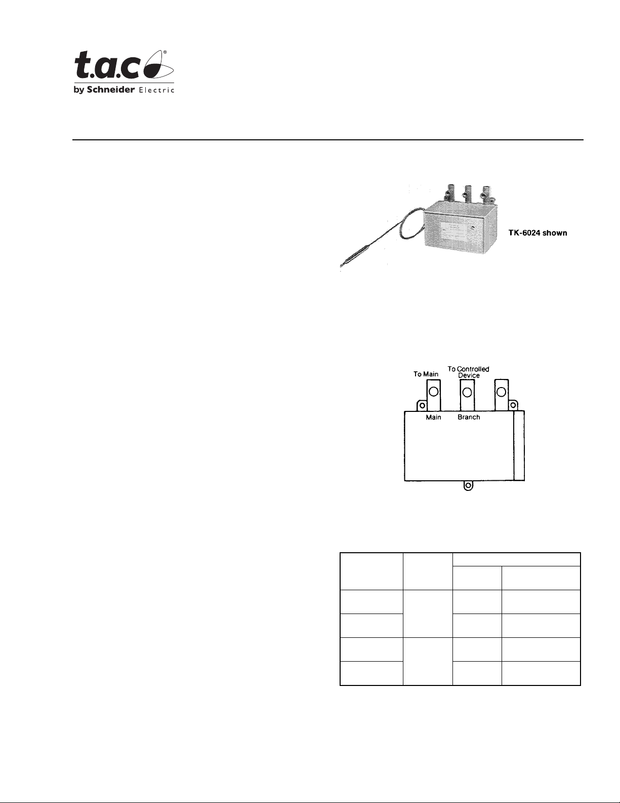
TK-6024, TK-6124, TK-8024,
TK-8124
Pneumatic Bulb Thermostats
General Instructions
MAINTENANCE PARTS
AT-520-011 Relay repair kit
AT-528 Pilot restrictor kit
DYDK- 77-031 Thermal element for TK-8X24
DYDK- 99-011 Thermal element for TK-6X24
Figure-1 Piping Connections.
Table-1 Specifications.
Bulb
Part Number Action
TK-6024
TK-8024 Averaging
TK-6124
TK-8124 Averaging
a
Direct Acting (DA) - increase output pressure on temperature rise.
Reverse Acting (RA) - Decrease output pressure on temperature rise.
DA
RA
a
a
Style
Straight
Straight
Dimensions
in (mm)
3/8 x 4-5/ 8
(9.5 x 117)
3/32 x 8’
(2.4 x 2.4 m)
3/8 x 4-5/ 8
(9.5 x 117)
3/32 x 8’
(2.4 x 2.4 m)
Printed in U.S.A. 8/08 © Copyright 2008 TAC All Rights Reserved. F-14684-4
Page 2
PRE-INSTALLATION
Inspection
Visually insp ect the car ton for damage . If da maged, not ify t he
appropriat e carrier imme diately. Visuall y inspect the device for
obvious defects. Return damaged or defective products.
Required Installation Items
• Tools (not provided):
Appropriate dri ll , drill bits and screwdriver for mounting
screws
Needle nose pliers or 3/ 16" open-ended wrench to hold
dial shaft
• Appropriate Accessories
• Mounting screws and appropriate fitt ings (not provided)
INSTALLATION
Caution:
technician.
Make all connections in accordance with the job piping
diagrams, local and national codes.
Avoid locations near steam or hot water coils or pipes, or
wherever radiant heat will affect the bulb or cap il lary tube.
Installer must be a qualified, experienc ed
THERMOSTAT MOUNTING
Mount the thermostat in an upright position on a wall or
vertical fla t surface that does not vibrate.
Three (3) mountin g holes 3/16
" (5 mm) pr ovided on cas e.
BULB MOUNTING
Table-2 Liquid Line and Tank for TK-6X24.
Part Number Description Mt. Fitting
a
AT-201
AT-203
AT-206 Copper bulb well 1/2" MNPT
AT-209
a
Requires AT-208.
b
Recommended installation is with a bulb well.
Copper bulb well
Stainless steel bulb
a
b
well
Bulb mounting kit 3/4" MNPT
3/4" MNPT
Insertion
Size
1/2" dia.
OD (9-1/2”
long
1/2" dia.
OD 4-1/2"
long
Lengt h of
bulb
Figure-2 Mounting Dimensions.
Figure-3 Bulb Well Install ation.
Table-3 Application Limitati ons at 250°F Fluid Temp.
(Max. 350°F)
Part Number
AT-201 11 250
AT-203 20 500
AT-206 11 250
AT-209 4150
Max. Recommended
Velocity (FPS)
Max.
Recommended
Stati c Pressur e
(psig)
Installation of TK-6X24 Bulb into AT-206
Bulb Well
1. Install AT-206 bulb well into 1/2" FNPT opening.
2. Place packing (included with AT-206) over bulb support
section a nd in s er t b ul b into w e ll.
3. Push packing into nut on well using a screwdr iver.
2 © Copyright 2008 TAC All Rights Reserved. F-14684-4
Page 3
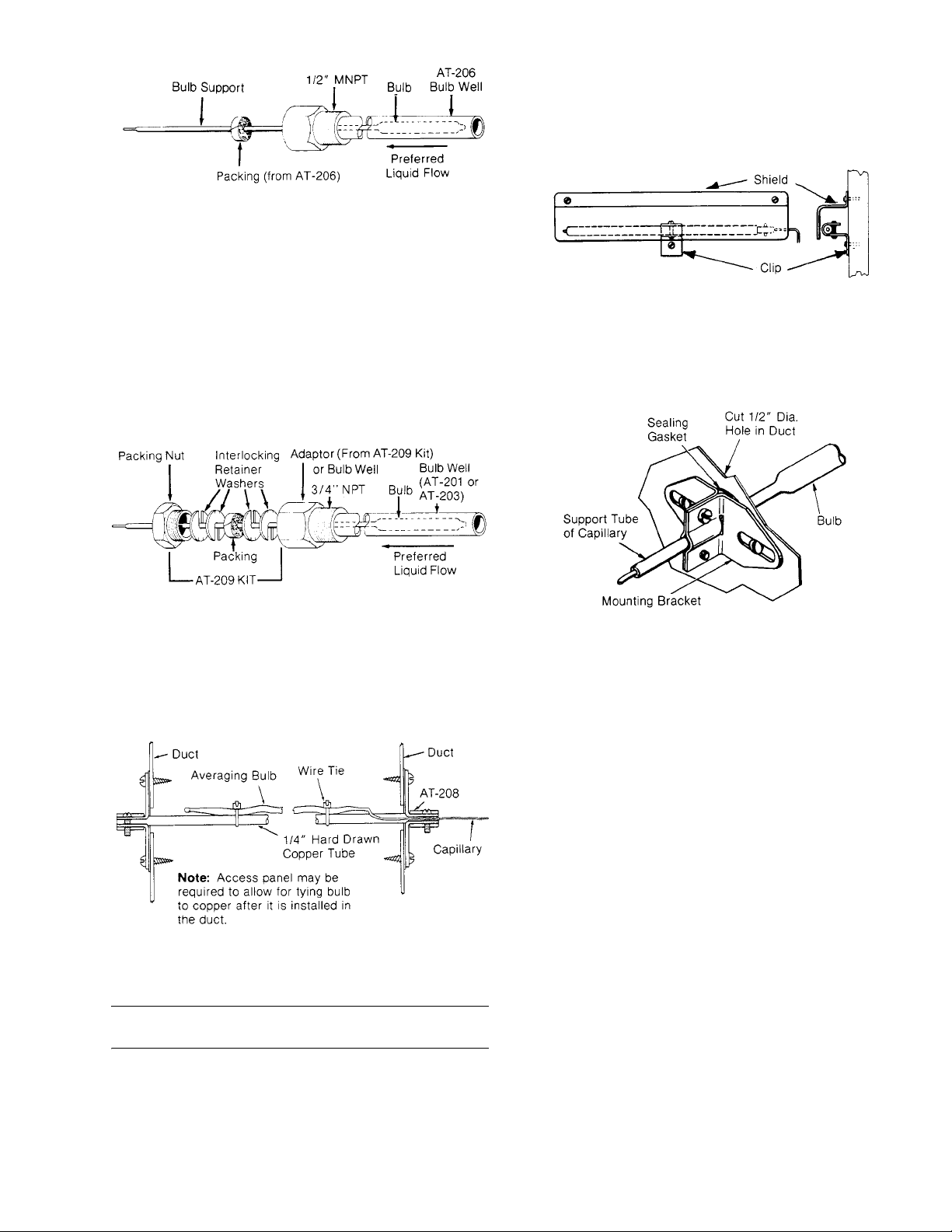
Figure-4 Installation of TK-6X24 into AT-206 Bulb Well.
Installation of TK-6X 24 Bulb in to AT -201 or
AT-203 Bulb Well (Requires AT-209 Kit)
Outdoor Installation of TK-6X24
Install with AT-211 kit as shown below.
1. Mount bulb to outside wall or surface with bulb clip.
2. Place shield over bul b and fasten to mounting surface.
1. Install bulb well or adaptor from AT-209 into 3/4" FNPT
opening.
2. Place packing nut, washers and packi ng fr om AT-209
over bulb support section and insert bulb into well or
AT-209 adaptor.
3. Push interlocking washers and packing into well or
adaptor and tighten packing nut until firmly sealed.
Figure-5 Installati on of TK-6X24 Bulb int o AT-201 or AT-203
Bulb Well with Required AT-20 9 Kit .
Duct Instal lation of TK-8X24
Install avera ging bulb mounting with two AT-208 kits as sho wn
below.
Figure-7 Installation of TK-6X24 Using AT-211 Outside Bulb
Shield.
Duct Installation of TK-6X24
Install bulb with AT-208 kit as shown below.
Figure-8 Installation of TK-6X24 Using AT-208 Duct
Mounting Kit.
ADJUSTMENTS
Thermostats are shi pped from the factory calibr ated to
provide an 8 psig control line pressur e when the cont rol point
is equal to the setpoint.
To make all adjustments, remove the cover by first lo osening
the cover screws. Squeeze sli ghtly on the top and bot tom and
pull forward and down, unhooking the top first.
Setpoint Dial
The thermostat has a total dial range of -20° to +240°F. One
side of the dial i s marked -20 to 120 and the other 10 0 to 240.
If a setpoint higher than 120° is required, proceed as follows:
1. Rotate setpoint dial to 110°.
Figure-6 Installation of TK-8X24 Using AT-208 Duct
Mounting Kit.
Note:
Access panel ma y be requi red t o allow f or ty ing bul b to
copper after it i s installed in the duct.
F-14684-4 © Copyright 2008 TAC All Rights Reserved. 3
2. using a 3/16
setpoint dial.
3. Loosen screw that holds dial in place and remove.
4. Remove dial and turn over to the 100 to 240 side.
5. Start screw int o dial po st, bef ore tight ening l ine up di al at
110°, and tighten. Be sure to hold dial post with wrench
when tightening screw ti ght.
6. Proceed with standard throttling rang e and calibration
procedures.
" open end wrench, hold hex shaft below
Page 4
Throttling Range
The throttling range should be set at the lowest value
which will allow th e thermostat to control the system
without cyclin g under norm al load conditions. The most
satisfactory setting will vary with he type of control system.
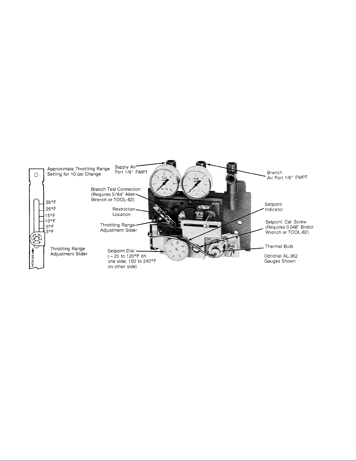
The throttling range is changed by sliding the throttling range
adjustment sl ider to its proper position. See Figure 9.
Calibration of the thermostat should be checked after the
throttling range has been changed. When making the
throttling range adjustment, ca re should be taken to prevent
excessive side forces on the feedback lever. In no case
should the pi vot poi nt be r aised when the a djust ment is made .
Throttling Range Adjustment
If the throttl ing range of the thermostat as shi pped is not
satisfactory, proceed as follows:
1. Move slid er to appr oxim ate posi tion desi red (see F igu re 9) .
2. With instrument measuring a stable temperature, rota te
setpoint dial CCW to low end of scal e, then CW to that
temperature “s etpoint”.
3. Adjust setpoint calibration screw until 3 psig (RA) or 13
psig (DA) is read on branch gauge.
4. Rotate setpoint dial CW toward upper end of scale until
13 psig (RA) or 3 psig (DA) is read on branch gauge.
5. Difference between setp oint dial read ing s in st ep 2 and 4
is the approximate m echanical throttli ng range of the
thermostat. The thermal throttli ng range will be equal to or
less than the mechani cal throttling range.
6. If the throttling range in step 5 does not provide the
control desi red, move throttling range slider in
appropriat e direction and repeat steps 2 through 5 until
desired contr ol is obtained. I f unable to obtain sat isfactory
control, check system for proper sizing of components
being controlled and sensing element location.
Figure-9 Thermost at Adjustments.
4 © Copyright 2008 TAC All Rights Reserved. F-14684-4
Page 5

CALIBRATION
After the installation has been completed, the thermostat
should be checked for calibration. As a nominal cali bration,
the controlled branch pressure should be 8 psig when the
setpoint is equal to the bulb temperature, indicated by a
thermometer loc ated near the bulb. In some applications, a
value other than 8 psig wi ll be required to get the desired
control results. Change the 8 psig will be requir ed to get the
desired contr ol results. Change the 8 psig designation as
used in the calibration procedure, should this be the case.
1. Using the branch gauges, or a separate test gauge
connected to the branch test port (see Note), rotate the dial
[direct acting (DA) - lower, reverse acting (RA) - raise] in
the appropriate direction. The branch pressure should
raise to be the same as the supply pressure ±1 psi.
Note:
As shown in Figure 9, each thermostat is furnished
with a branch test connection. If a test gauge is to be used at
this connection, use a 5/64" Allen wrench to unsc rew
(countercl ockwise) the test point scr ew one full turn before
attaching te st gauge.
2. Measure the temperature at the bulb. Thi s mu st be a
stable tempera ture.
3. Rotate the dial to this temperature.
4. Turn the setpoint calibration screw (see Figure 9) until a
branch pressure of 8 psig ±1 psi is read on the branch
gauge.
1. Remove restriction cover plate, restriction and two gaskets
(see Figure 9 for location).
2. Using the parts from the AT-539 place in order one
gasket, restrictor plate, the other gasket and cover plate
with the tubing attached on the restrictor mount ing pad.
Then install the two (2) screws.
3. Route 5/32" pla stic tubing through hole i n base and
connect to constant 15 or 20 psig main.
Calibration When Used As Low Limit
1. Determine throttling range required . This normally is
appro ximate ly 10°F.
2. Adjust branc h pressure from first thermos tat to maximum
branch pressure.
3. Adjust thro tt li ng range as described in Thro ttling Range
Adjustment on page 3.
4. After thrott ling range is ad justed, proceed with calib ration
of control point as descr ibed in Calibration.
FIELD SERVICE
Relay repair kit, pilot restrictor and thermal elements
are available. See Maintenance Parts on page 1 for
specific part numbers.
Note:
The hex nut on the adjusting screw is used to provide
tension only and should not be loosened when making
adjustments.
5. Turn the dial to the desired setpoint.
6. If separate test gauge is used, remove gau ge, tighten test
point screw and replace cover.
7. Observe operation of system for satisfactory control. If
necessary, recalibrate after system has come in control
and stabilized.
USE AS A LOW LIMIT THERMOSTAT
These thermostats may be used as low limit thermostats.
Normally in this application, they are used in series with the
branch pressure of another proportional thermostat. When
using two proportional thermostats in series, the second unit
must have an exter nal main air source for the pilot cham ber of
the thermostat. This is required to insure the operation of the
second thermostat at low branch pressure fr om the first
thermostat. An external pilot pressure kit is required for this.
The part number of this kit is AT-539.
Attachment of AT-539
To attach the AT-539 external pilot pressure kit, use the
following procedure.
MAINTENANCE
Regular maintenance of the total system is
recommended to assure sustained optimum
performance.
F-14684-4 © Copyright 2008 TAC All Rights Reserved. 5
Page 6

6 © Copyright 2008 TAC All Rights Reserved. F-14684-4
Page 7

F-14684-4 © Copyright 2008 TAC All Rights Reserved 7
Page 8

Copyright 2008, TAC
All brand names, trademarks and registered
trademarks are the property of their respective
owners. Information contained within this
document is subject to change without notice.
F-14684-4
TAC
1354 Clifford Avenue
P.O. Box 2940
Loves Park, IL 61132-2940
www.tac.com
 Loading...