

Page 1
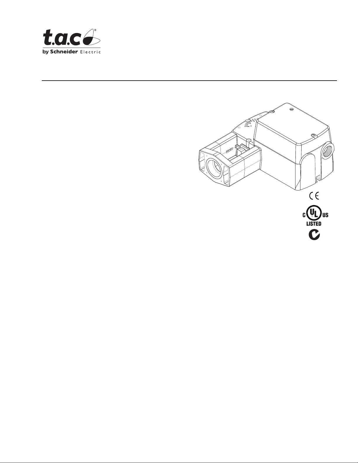
Application
TAC DuraDrive Linear Actuators are designed to
mount directly onto two-way or three-way globe valves
without the use of linkages. They provide linear travel
to operate valves from 1/2" to 2" VB-7xxx and
discontinued 1/2" to 1-1/4" VB-9xxx in chilled water, hot
water and steam applications up to 366 °F (186 °C).
Linear spring return actuators provide either two
position, floating or proportional modulation control
(depending on model selection) of valves in HVAC
systems.
MA51-710x Two Position Series
MF51-71 03 Floati ng Series
MS51-7103 Proportional Series
TAC DuraDrive™ Linear Series
Spring Retur n Actu ato r
General Instructions
Features
• Two position models controlled by SPST controller
• Floating models controlled by SPDT floating
controllers
• Proportional models controlled by 0-3 Vdc, 6-9 Vdc,
0-10 Vdc, 0-20 mAdc, 2-10 Vdc, or 4-20 mAdc.
Control function direct/reverse action is jumper
selectable
• 105 lb force (467 newton) with 1/2" (13 mm) nominal
linear stroke
• 24 Vac, 120 Vac, and 230 Vac models
• Rugged polymer housings rated for up to
NEMA 2/IP54
• Overload protection throughout stroke
• Automatically sets input span to match valve travel
• Compact size to allow installation in limited space
• Manual override to allow positioning of valve and
preload
• Spring return operation
Mx51-710x
• Direct mount to valves without separate linkage
• Polymer housing rated for plenum use
• Five year warranty
Printed in U.S.A. 8-08 © Copyright 2008 TAC All Rights Reserved. F-27169-6
Page 2

Applicable Literature
F-Number Description Audience Purpose
– Application Engineers
F-26080 EN-205 Water System Guidelines
F-27252
F-26895
F-27175
F-27382 TAC Electric/Electronic Product s Catalog
Vx-7xxx-8xx Series Vx-7xxx-59x Series Vx-9xxx-8xx
Series Vx-9xxx-59x Series Selection Guide
AM-703 Input Scaling Module, AM-704 Pulse Width
Modulation Interface, AM-705 Positioner, AM-706
Positioner, AM-708 Resistor
AM-756 Metric Conduit Adapter, AM-763 Hexcrank, AM770 Replacement Valve Linkage Par ts Kit
–Installers
– Service Personnel
– Start-up Te chnician s
– Sales Personnel
– Application Engineers
–Installers
– Service Personnel
– Start-up Te chnician s
–Installers
– Service Personnel
– Start-up Te chnician s
– Sales Personnel
– Application Engineers
Descri bes TAC approved water tr ea tm en t
practices.
Provides Mxx1-720x and Mx51-710x
actuator, valve, and valve assembly
select ion data includin g specifications,
close-off pressur es, and dimensional
information.
Provides step-by-step mounting
instructions
Provides step-by-step mounting
instructions
Comprehensive catalog containing TAC’s
electric/electronic actuators, thermostats,
controllers, sensors, tr ansmitte rs, and
accessories
SPECIFICATIONS
Actuator In puts
Control Signal: See Table-1 for actuator models and control type.
Power Input: See Table-1. All 24 Vac circuits are Class 2. All circ uit s 30 VAC and above
are Class 1.
Connections: 3 ft (91 cm) appliance wire or plenum cables, enclosure accepts 1/2” (13
mm) conduit connectors. For M20 Metric connector, use AM-756 adaptor.
Actuator Outputs
Electrical:
Position Feedback Vol tage (proportional or floating only),
For voltage r anges, the feedback signal is the same r ange as the input signal. The 420 mAdc current range and floating actuators have a 2-10 Vdc position feedback
signal. The pos it ion feedback signal can supply up to 0.5 mAdc to operate up to four
additional slave actuators.
Mechanical:
Linear Stroke, 1/2” (13 mm) nominal.
Approx. Stroke Timing, See Table-1.
Manual Override, Allows positioning of valve and preload using manual crank.
Right/Left Jumper, Permits reverse acting/direct acti ng li near motion (MS51 only).
Environment:
Ambient Temperature Limi ts,
Shipping & Storage, -4 0 to 16 0 ° F ( - 40 to 71 °C ).
Operating, -22 to 140 °F (-30 to 60 °C).
Temperature Restrictions, For maximum ambient 140
°F (60 °C) the maximum
allowable flui d temperature should not exceed valve rating. See F-2 7252 Selection Guide
for specific ratings.
Humidity: 5 to 95% RH, non-condensing.
Location:
NEMA 1. NEMA 2 (enclosure is air plenum rated), UL Type 2 (IEC IP54) with customer
supplied water tight conduit connectors.
Agency Listings
UL 873: Underwriters Laboratories (File #E9429 Category Temperature-Indicating and
Regulating Equipment).
CUL: UL Listed for use in Canada by Underwriters Laborat ories. Canadian Standards
C22.2 No. 24-93.
European Community: EMC Directi ve (89/336/EEC). Low Voltage Dire ctive (72/23/ EEC).
Australia: This produc t meets requi rements to bear the C-Ti ck Mark accor ding to th e terms
specified by the Com mu nications Authority under the Radio Communications Act 1992.
2 © Copyright 2008 TAC All Rights Reserved. F-27169-6
Page 3

Note:
All performance specifications are nominal and conform to acceptable industry
standards. For applications at condit ions beyond these specif ications, consult TAC. TAC
shall not be liable for damages resulting from misapplication or misuse of its products.
Table-1 Specifications.
Actuator Power Input Approximate Stroke
Running Holding
50/60 Hz
VA W W
DC
Amps
50/60 Hz
b
b
b
b
b
b
b d
b d
b
b
b
b
Control
Signal
Two
Position
SPST
Floating
2-10 Vdc
Proportional
0-3 Vdc
Proportional
6-9 Vdc
Proportional
0-10 Vdc
Proportional
4-20 mAdc
Voltage Wiring System
24Vac ±2 0%
20-30 Vdc
120 Vac ±10%
50/60 Hz
230 Vac ±10%
50/60 Hz
c
24Vac ±2 0%
20-30 Vdc
Appliance Wire 5.3 4.1 0.15 1.2
Appliance Wire 7.9 6.2 n/a 2.1
Appliance Wire 7.4 5.4 n/a 2.1
Appliance Wire 6.9 4.7 0.16 2.1
Appliance Wire 6.6 4.2 0.14 1.5
Plenum Cable 6.6 4.2 0.14 1.5
Appliance Wire 6.6 4.2 0.14 1.5
Plenum Cable 6.6 4.2 0.14 1.5
Appliance Wire 6.6 4.2 0.14 1.5
Plenum Cable 6.6 4.2 0.14 1.5
Appliance Wire 7.8 4.9 0.16 3.4
Plenum Cable 7.8 4.9 0.16 3.4
Appliance Wire 6.6 4.2 0.14 1.5
Plenum Cable 6.6 4.2 0.14 1.5
Appliance Wire 6.6 4.2 0.14 1.5
Plenum Cable 6.6 4.2 0.14 1.5
Part Number
MA51-7103-000
MA51-7103-100 Plenum Cable 5.3 4.1 0.15 1.2
MA51-7100-000
MA51-7101-000
MF51-7103-000
MF51-7103-100 Plenum Cable 6.9 4.7 0.16 2.1
MS51-7103-000
MS51-7103-100
MS51-7103-020
MS51-7103-120
MS51-7103-030
MS51-7103-130
MS51-7103-040
MS51-7103-140
MS51-7103-050
MS51-7103-150
MS51-7103-060
MS51-7103-160
a
Timing was measured with the actuator mounted on a VB-7xxx Series valve.
b
Proportional (MS) models shipped with RA/DA jumper set for DA (actuator extends with increasing signal).
c
4-20 mAdc with AM-708 500 ohm field-installed resistor.
d
Has 20 Vdc power supply for System 8000 applications.
Timing in Seconds
@ 70F (21°C)
Powered
a
Spring
Return
44 19
60 16
Globe Valve Close-Off Pressures: For close-off pressure ratings on globe valve
assemblies, consult Linked Globe Valve Assemb li es with TAC DuraDrive Linear Series
Actuators Selection Guide F-27252.
ACCESSORIES
AM-756 Metric Conduit Adapter M20 x 1.5 to 1/2” NPT
AM-770 Replacement valve linkage parts kit
AM-764 Linkage kit for damper applications
MS51-7103
AM-703 Input re sc a lin g module, adjust sign als to 2-10 Vac , ze r o an d sp an adjust
AM-704 Interface, p ulse width modulation (PWM)
AM-705 Positioner (NEMA 4 housing)
AM-706 Min and/or manual positioner for flush panel mount
AM-708 500 ohm resistor for 4 to 20 mA c ontrol signal
F-27169-6 © Copyright 2008 TAC All Rights Reserved. 3
Page 4
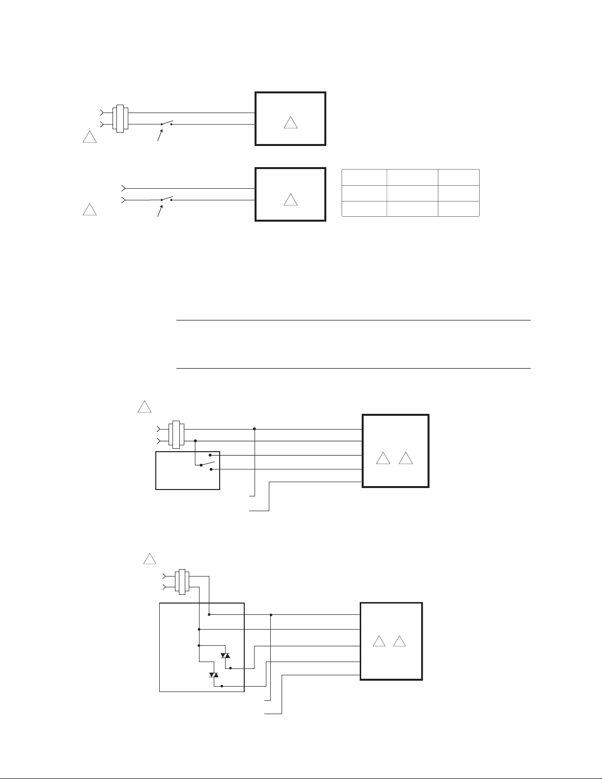
TYPICAL TWO POSITION CONTROL (wiring diagrams)
Figure-1 illustrates typical wiring diagrams for spring return two-position MA51-710x
actuators. See Table-1 for model selection. See 8 for wiring diagrams notes gui de.
24 Vac Transformer
or 20-30 Vdc
Line
Volts
1
Blk
Red
SPST Control Contact
Hot (+DC)
Com
MA51-7103-xxx
8
MA51-710X-xxx
120 Vac or
230 Vac
1
L1
L2
SPST Control Contact
Hot
N
8
Figure-1 Typical Wiring Diagrams for Two Position Actuators
TYPICAL FLOATING CONTROL (wiring diagrams)
Figure-2 through Figure-5 illustr ates typical wiring diagrams for spring return floating
MF51-7103 actuators. See Table-1 for model selection. See 8 for wiring diagrams notes
guide.
Caution:
powered off transformers used to power other devices utilizing non-isolated full-w ave
rectifier power supplies. Refer to
Common Transformer, F-26363
24 Vac Transformer
1
or 20-30 Vdc
Line
Volts
Typical
Floating
Controller
Feedback Signal
2 to 10 Vdc
This product contains a half-wave rectifier power supply and must not be
for detailed information.
Black
Red
Blue
(-)
(+)
Voltage L1 N L2 Hot
120 Vac White Black
230 Vac Blue Brown
EN-206, Guidelines for Power Multiple Devices from a
Common
Hot (+DC)
Extend
RetractYellow/Black
Violet
MF51-7103-xxx
2 8
Figure-2 Floating Point Cont rol
24 Vac Transformer
1
or 20-30 Vdc
Line
Volts
Hot
Controller
Common
Feedback Signal
2 to 10 Vdc
(-)
(+)
Black
Red
Blue
Yellow/Black
Common
Hot (+DC)
Extend
Retract
Violet
MF51-7103-xxx
2 8
Figure-3 Triac Source
4 © Copyright 2008 TAC All Rights Reserved. F-27169-6
Page 5
24 Vac Transformer
1
or 20-30 Vdc
Line
Volts
Controller
24 Vac Transformer
1
or 20-30 Vdc
Line
Volts
Controller
Hot
Hot
Common
Feedback Signal
2 to 10 Vdc
Common
(-)
(+)
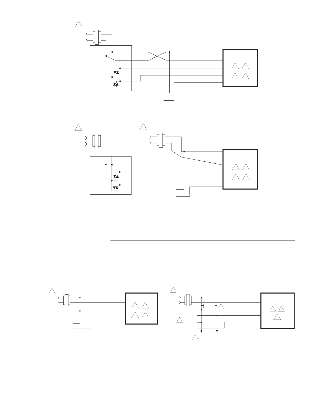
Figure-4 Triac Sink
24 Vac Transformer
1
or 20-30 Vdc
Line
Volts
Yellow/Black
Feedback Signal
2 to 10 Vdc
Black
Red
Blue
Yellow/Black
Violet
Black
Red
Blue
(-)
(+)
Violet
Common
Hot (+DC)
Extend
Retract
AO
Common
Hot (+DC)
Extend
Retract
AO
MF51-7103-xxx
2
3
4 8
MF51-7103-xxx
2
3
4 8
Figure-5 Triac Sink With Separat e Transformers
TYPICAL PROPORTIONAL CONTROL (wiring diagrams)
Figure-6 illustrates typical wiring diagrams for spring return proportional MS51-7103
actuators. See Table-1 for model selection. See 8 for wiring diagrams notes gui de.
24 Vac Transformer
1
Line
Volts
Vdc or mAdc
Control Signal
Vdc
Feedback Signal
or 20-30 Vdc
(-)
(+)
(-)
(+)
Caution:
powered off transformers used to power other devices utilizing non-isolated full-w ave
rectifier power supplies. Refer t o
Common Transformer, F-26363
Vdc Proportional Control
Blk
Com
Red
Hot (+DC)
Yel/Blk
Violet AO
Figure-6 Typical Wiring Diagrams for Proportional Control 24 Vac Basic Models
This product contains a half-wave rectifier power supply and must not be
EN-206, Guidelines for Powering Multipl e Devices from a
for detailed information.
4 to 20 mAdc with 2-10 Vdc Actuators
or 20- 30 Vdc
(-)
(+)
4
(-)
(+)
2
MS51-7103-xxx
AI
2
6 8
24 Vac Transformer
1
Line
4
Volts
Control Signal
4 to 20 mAdc
Feedback Signal
2 to 10 Vdc
500 Ω
To Additional
2-10 Vdc
Actuators
Blk
Red
Com
Hot (+DC)
5
Yel/Blk
Violet
AI
AO
MS51-7103-x00
2
4
8
F-27169-6 © Copyright 2008 TAC All Rights Reserved. 5
Page 6
24 Vac Transformer
V
1
or 20-30 Vdc
Line
Volts
Control Signal
2 to 10 Vdc
(-)
(+)
Blk
Red
Yel/Blk
Violet
Com
Hot (+DC)
AI
AO
MS51-7103-xxx
2 3
8
Feedback Signal
2 to 10 Vdc
(-)
(+)
Blk
Red
Yel/Blk
Violet
Com
Hot (+DC)
AI
AO
MS51-7103-xxx
2 3
8
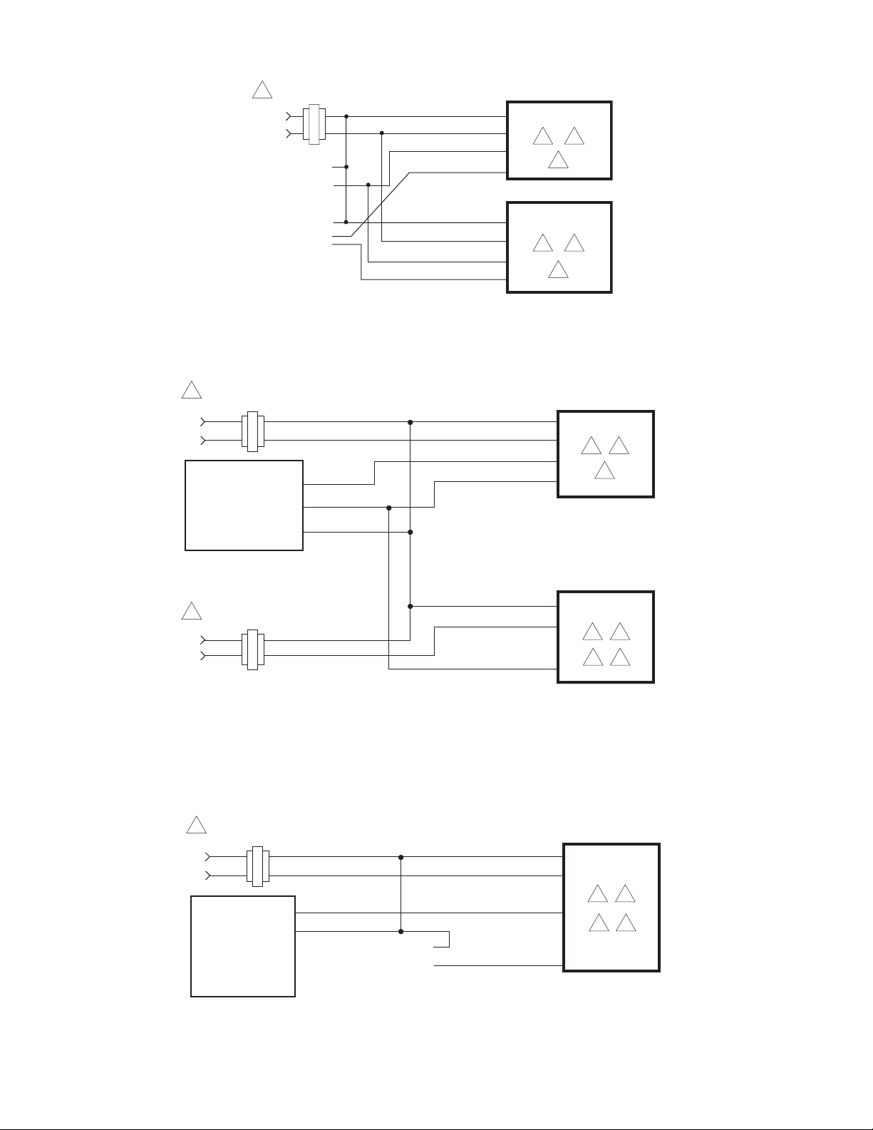
Figure-7a Typical Wiring Diagrams for Proportional Control 24 Vac Model s Wired in Parallel
24 Vac Transformer
1
or 20-30 Vdc
Line
Volts
Typical Controllers
CP-8102
TP-810X
TP-8121
TP-8124
TP-8232
System 8000 controller
requiring external 20 Vdc
power from actuator
24 Vac Transformer
1
or 20-30 Vdc
Line
Volts
Blk
Red
Red (+20)
Yellow (OLP1)
Blue (COM)
Blk
Red
Com
Hot (+DC)
White/Red
Yel/Blk
Com
Hot (+DC)
Yel/Blk
MS51-7103-x40
24
8
MS51-7103-x40
2
4
78
Figure-7b Typical Cont rol Wiring for Two MS51-7103- x40 to System 8000 Controllers
Requiring External 20 Vdc Power from Actuator
24 Vac Transformer
1
or 20-30 Vdc
Line
olts
Typical System
8000 Controllers
CC-8111
CC-8118
CC-8218
CP-8161
CP-8261
Figure-7c Typica l Control Wiring for MS51-7103-x40 to Contr ollers not Requiring
OP1
COM
Vdc
Feedback Signal
6 to 9 Vdc
(-)
(+)
Blk
Red
Yel/Blk
Violet
Com
Hot (+DC)
AI
AO
MS51-7103-x40
24
78
External 20 Vdc Power from Actuat or
6 © Copyright 2008 TAC All Rights Reserved. F-27169-6
Page 7

1 Provide overload protection and disconnect as
required.
2 Actuators may be wired (120V mA does not have red
wire and 230V mA does not have red or black wires)
in parallel. All actuator black wires are connected to
the transformer common and all red wires are
connected to the hot lead. Power consumption must
be observed.
3 The Common connection from the actuator must be
connected to the Hot connection of the controller. The
actuator Hot must be connected to the controller
Common.
4 If the controller uses a full-wave power supply and
does not provide isolated outputs, a separate
transformer is required.
Figure-8 Wire Diagram Notes Guide
5 A field-supplied 500 ohm resistor (AM-708) is
required for this application.
6 On MS51-7103-X60 (4-20 mAdc) models a 500
ohm resister is incorporated in the product. Do
not use an external resistor.
7 If using multiple MS51-7103-040's with TAC
System 8000 controller requiring 20 Vdc
power; tape off red +20 Vdc power supply
leads on all but one actuator.
8 Cable on some models contains more wires
than are used in applications. Only those
wires actually used are shown.
INSTALLATION
Inspection Inspect the pack age for damage. If damaged, noti fy the appropriate carr ier immediately. If
undamaged, open the package and inspect the device for obvious damage. Retu rn
damaged products.
Requirements • Job wiring diagrams
• Appropriate accessories
• Pliers for removing and inserting connecting pin
• Installer must be a qualified, experienced technician
• TOOL-37, 1 5/8” open end wrench for valve mounting nut
• 5/16” and 7/16” open -end wrench for stem jam nuts and stem extension
• #8 Torx screwdriver (not provided)
Precautions General
Warning:
• Electrical shoc k hazar d! Dis conne ct th e power suppl y (l ine p ower) b efore ins tallat ion t o
prevent elect ri c shock and equipment damage.
• Make all con nect ions in acc ord ance wit h the job wi r ing di agram an d i n accor danc e wit h
national and local electrical codes.
• Floating and Proportional Models: These products contain a half-wave rectifier power
supply. They must not be powered with transformers that are used to power other
devices utilizing non-isolated full-wave rectif ier power supplies. Refer to EN-206,
Guidelines For Powering Devices From A Common Transformer , F-26363 for detai led
information.
Caution:
• Avoid electrical noise interfer ence. Do not install near lar ge contactors, electrical
machinery, or wel ding equipment.
• Manual overrid e to be used onl y when power is not applied to unit .
• When operating manual override (observe position indicator), back off 5° from full
extended mechan ical stop to ensure proper rel ease.
• Use with fluid temperatures above 100°C requires insulati on on the pi pe and control
valve.
Federal Communications Commission (FCC)
Use copper conductors only.
Note:
This equipment has been tested and found to comply with the li m it s for a Class B
digital device, pursuant to Part 15 of the FCC Rules. Thes e li m it s are designed to provide
reasonable prot ection against harmf ul interference in res idential install ations. This
equipment generates, uses, and can radi ate radio frequency energy and m ay cause
F-27169-6 © Copyright 2008 TAC All Rights Reserved. 7
Page 8

harmful interference if not instal led and used in accordance with the instructions. Even
when instruct ions are followed, there is no guarantee that interfe rence will not occur in a
particular s etti ng—Which can be determi ned by turn ing the equipment of f and on—th e use r
is encouraged to t ry t o correct the interference by one or more of the followin g mea sures:
• Reorient or relocate the receiving antenna.
• Increase the separation between the equipment and receiver.
• Connect the equipment to an outlet on a c ir cuit different from that to which the receiv er
is connected.
• Consult the dealer or an experienced radio/television technician for help.
Canadian D epartment of C om m u ni c at ions (D OC )
Note:
This Class B digital apparatus meets all requirements of the Canadian Interference-
Causing Equipment Regulations.
Cet appareil numerique de la classe B respecte toutes les exigences du Reglemen t sur le
material broil leur du Canada.
European Standard EN 55022
Location
Warning:
environment this product may cause radio interference in which case the user may be
required to take adequate measures.
Caution:
explosive vapors are present.
This is a Class B digital (Eur opean Classification) product. In a domestic
Avoid locations where excessive moisture, corrosive fumes, vibration, or
Mounting • Mount the linear actuator directly on the valve in locations that clear the maximum
dimensions of the actuator case (see Figure-12).
• Ensure that the valve body is installed corr ectly. The arrow must point in the direction
of flow. With thr ee-way valves obs erve stem positi on (stem up or stem down) for proper
flow characteristics. See Table 3.
• It is preferab le that the act uator is mount ed above the val ve body. This will minimize the
risk of damage to the actuator in the event of condensation or a valve leak. Refer to
Figure-10.
Changing Control Function (proportional units only)
These actuator s are equipped with a j umper to contro l the function of the signal as rece ived.
See Figure-9. Fac tory setting is for direct acting. Remove cover to change jum per setting.
8 © Copyright 2008 TAC All Rights Reserved. F-27169-6
Page 9
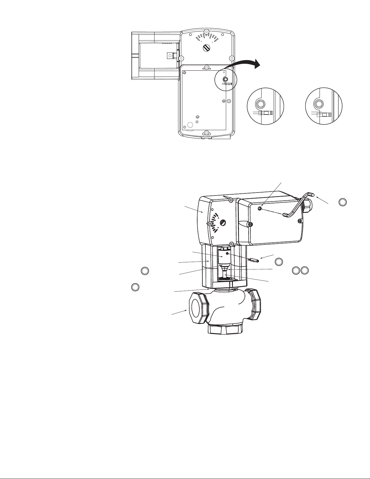
Direct Acting
(pins connected)
Reverse Acting
(pins open)
Mounting Bracket
3
Stem Extension
4
Hex Mounting Nut*
Actuator extends
with increased signal.
Figure-9 RA/DA Jumper Setting for Proportional Models
Manual Override
Actuator
Rack
Connecting Pin
6
Jam Nut
Valve Stem*
Actuator retracts
with increased signal.
Crank
2
1
5
Valve Body*
*Not included with actuator.
Figure-10 Mx51-710x Ser ies Actuator Exploded View
Installation: Mx51-710x Series Actuator to 1/2" to 2" VB-7xxx Series Valve
Bodies, 2-Way Stem-Up Closed and 3-Way Mixing or Diverting Applications
A. Preload the valve to i nsure proper close-of f according to the numbered steps in
Figure-10 and th e text below. (Remove power before pro ceeding.)
1. Locate t he st eel jam nu t th at c ame packa ged w ith the actu ato r. ( Do no t re- use t he brass
jam nu t pres ent on an existing valve.)
2. Screw the nut onto t he val ve s tem all the way a s far as it will g o ( you may nee d to us e
a TOOL-20-1 or a 5/16” open- end wrench). At least 1/2” of the valv e stem should
extend above the nut.
3. Thread the stem extension onto the valve stem, making contact with the jam nut.
Raise the valve stem to the f ull up position.
F-27169-6 © Copyright 2008 TAC All Rights Reserved. 9
Page 10

4. Orient the actuator mounting bracket on the valve and tighten the hex mounting nut
securely against the bracket using TOOL-37.
5. Insert the crank provided in the actuator cover. Wind the crank two turns
countercloc kwise. Press in t he turn cra nk 1/8 turn co untercloc kwise to lock i n position .
6. Rotate the stem extension un til the t hrou gh holes i n the stem ext ension and rack li ne
up. Insert con necting pin to secure stem extension and tighten jam nut against stem
extension usin g TOOL- 20-1 or a 5
B. Apply power to the actuat or and check the syste m operation for heati ng or cool ing output
in response to the control signal.
I
16” open end wrench.
Installation: Mx51-710x Series Actuator to 1/2" to 2" VB-7xxx Series Valve
Bodies, 2-Way Stem-Up Open
A. Preload the valve to insure proper cl ose-off accordi ng to t he num bered steps to 10 and
the text below. (Remove power before proceeding.)
1. Locate t he st eel jam nu t th at c ame packa ged w ith the actu ato r. ( Do no t re- use t he brass
jam nu t pres ent on an existing valve.)
2. Screw the nut onto t he val ve s tem all the way a s far as it will g o ( you may nee d to us e
a TOOL-20-1 or a 5/16” open- end wrench). At least 1/2” of the valv e stem should
extend above the nut.
3. Thread the stem extension ont o the valve stem, making cont act with the jam nut. Push
the valve stem to the full down position.
4. Orient the actuator mounting bracket on the valve and tighten the hex mounting nut
securely against the bracket using TOOL-37.
5. Insert the crank pr ovided in t he ac tuator cover . Wind t he c rank co unterc lockwi se u ntil
the actuator full y extends, then unwind 2 turn s and press in and turn crank 1/8 turn
counterclockwise to lock in position.
6. Rotate the stem extension until the through holes in the stem extension and rack
lineup. Inse rt connecting pin to secure stem extension and tight en jam nut against
stem extension usi ng TO O L-20-1 or a 5
B. Apply power to the actuat or and check the syste m operation for heati ng or cool ing output
in response to the control signal.
I
16” open end wrench.
Valve Mounting The valve should be mount ed in a weat her-protected area , in a locat ion that is within the
ambient temperat ure li mits of the act uat or. The instal lat ion of the actuator assembly sho uld
provide clearance on all sides to allow for any maintenance that may be needed (see
Figure-10 and Figure-11).
1. Followi ng general pi ping pr actices is recommended.
2. Apply pipe sealant sparingly to all but the last two threads of a properly threaded,
reamed, and cleane d pipe. Make su re the pipe chips, scale, etc. do not get into the pipe
since this mat erial m ay lodge in the va lve seat and pr even t proper closi ng and openi ng
of the valve. The valve must be piped with an inlet and an outlet.
3. Start the joint hand-thr eading the pipe into the valve. If the thread alignmen t fee ls
normal, continue to turn the pipe by hand as far as it will go.
4. Use a pipe wrench to fully tighten the pipe to the valve.
Caution:
or crushing the valve while tightening the pipe.
5. Insulate only the valve body and associated piping, not the actuator.
6. In chilled or cold water systems where the environment is humid, use a drip pan under
Caution:
weight. No load or weight should be resting on the actuator, long term damage may occur
to the actuator, mounting connection or the valve.
• Do not insulate the act uator/linkage. Doing so wil l result in excess heat buildup within
Do not over-tighten th e pipe, which may cause stripp ed thr eads. Avoid twisting
the valve to catch condensate.
The TAC DuraDrive linear actuator is designed to effectively support its own
the actuator.
10 © Copyright 2008 TAC All Rights Reserved. F-27169-6
Page 11
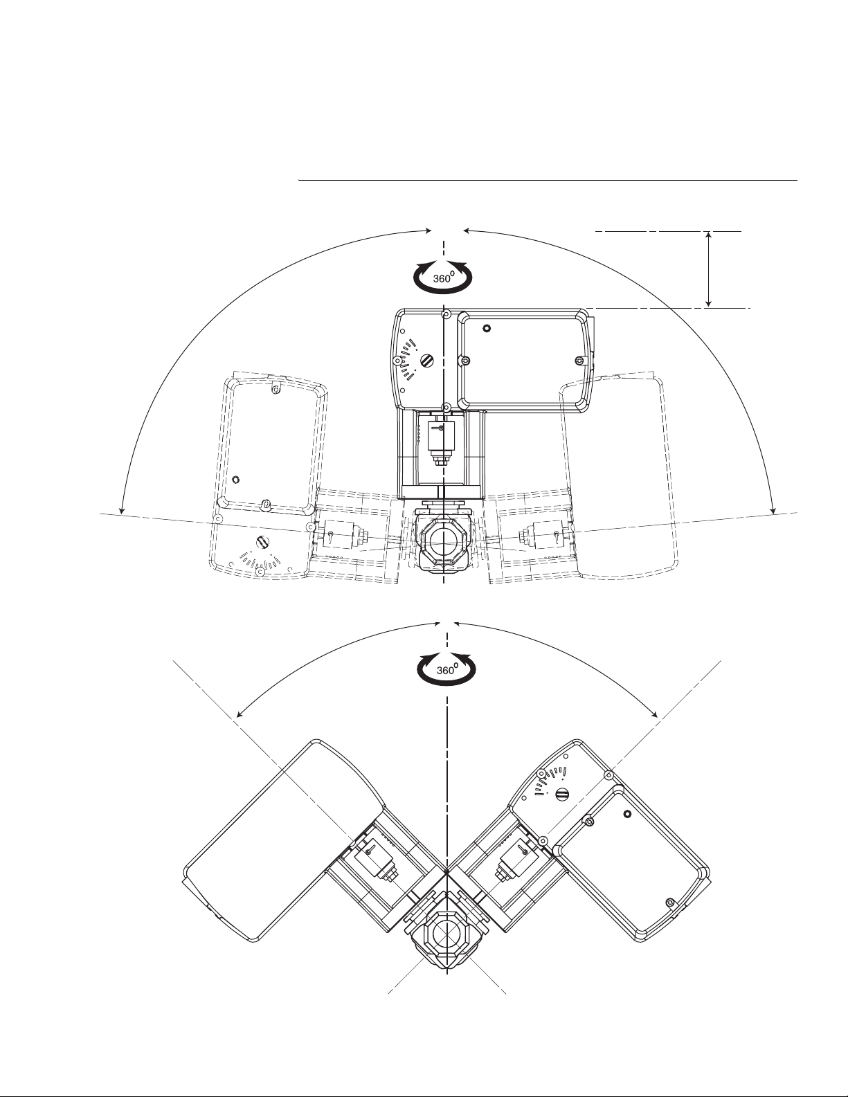
• For non-steam application the globe valve assembly must be mounted so that the
0
actuator is at leas t 5° above the horizontal (Figure-11) to ensure that any condensate
that forms will not travel into the mounting bracket or actuator.
• On steam applications, th e globe valve assembly must be mounted approximatel y 45°
from horizontal.
• Temperature Restrictions: For maximum ambient 140
allowable flui d temperature should not exceed valve rating. See F-27252 Sel ection
Guide for specif ic ratings.
0˚
°F (60 °C) the maximum
1-3/4 (45)
Minimum
Clearance
85˚
Max
Figure-11 Acceptable Mounting Orientations for Non-Steam Applicati ons
Approx.
45°
85˚
Max
Approx.
45°
Figure-12 Acceptable Mounting Orientation fo r Stea m Applications
F-27169-6 © Copyright 2008 TAC All Rights Reserved. 11
Page 12
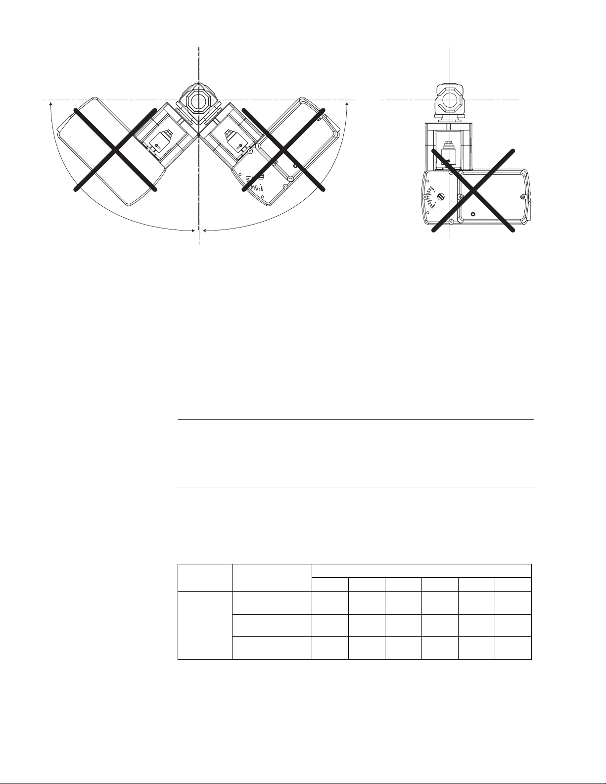
0°0°
90°90°
180°
Figure-13 Unacceptable Mounting Orientation
MANUAL OVERRIDE OPERATION
When necessar y, the actuat or’s ou tpu t shaft ca n be r epos itioned u si ng the manua l o verride
mechanism as follows:
1. Disconnect power from the actuator. The actuator will fully retract.
2. Without pushing down on the crank, crank the manual overr ide counterclockwi se until
the actuator extends to the desired posit ion. Push in until the mechanism locks in
position. (The manual override lock will rel ease the next time power is appli ed.)
3. If you desire to reposit ion the actuator manually from a locked position, turn the crank
1/8 turn counterclockwise and pull out to release. Adjust position as desired.
Caution:
• Only use manual overr ide when the actuator drive motor is not powered.
• Engaging the manual over ride when the act uator is p owere d may cause d amage to the
gears.
• Using power tools to adj ust the override will cause dam age to the gears.
Wiring Requirements Contr ol Leads
See Table-2 for power wiring data. Refer to Figure-1 throu gh Figure-7 for typical wiring.
180°
Table-2 Power Wiring
Actuator
Voltage
24 Vac
20-30 Vdc
Part Number
MA51-7103
MF51-7103
MS51-7103
12 AWG14 AWG16 AWG18 AWG20 AWG22 AWG
1678
(512)
1289
(393)
1140
(348)
Maximum Wire Run in ft. (m)
1055
(322)
810
(247)
717
(219)
664
(202)
510
(155)
451
(137)
417
(127)
321
(98)
284
(86)
263
(80)
202
(61)
178
(54)
208
(63)
160
(49)
141
(43)
CHECKOUT
After the entire system has been installed and the actuator has been powere d up, the
following check can be ma de for prope r system oper ation. Check for correct operation o f the
valve while actuator is being stroked.
1. Apply pow er to th e actu ator. Actuato r and val ve shoul d be dr iven t o their po wered positio n
12 © Copyright 2008 TAC All Rights Reserved. F-27169-6
Page 13

as determined by the control signal. Refer to Table-3 for valve flow.
2. Break power to the actuator. Actuator and valve should return to the spring return
position (retracted position).
Table-3 Assembly Configuration Chart
Valve Body Valve Body Action
VB-721x
VB-921x
VB-722x
VB-922x
VB-731x
VB-931x
VB-732x
VB-932x
a
Proportional models shipped with RA/DA jumper set for DA (actuator extends with increasing signal).
b
Discontinued 1/2” to 1-1/4” VB-9xxx.
Two-Way Stem Up Open Up Open A to AB flow decreases as actuator extends
b
Two-Way Stem Up Closed Up Closed A to AB flow increas es as actuator extends
b
Three-Way Mixing Up B to AB
b
Three-Way Diverting Up B to AB
b
Note:
Check that the transformer(s) are sized properly.
Normal Position
Valve Stem Flow
• If a common transform er i s used with multiple actuators, make sure that polari ty is
observed on the secondary. This means connecting all black wires to one leg of the
transformer and all red wires to the other leg of the transformer.
• If multiple t ransformers are used with one control signal, ma ke sure all black wires are
tied togethe r and tied to control signal negative (-).
• If the controll er uses a full-w ave power sup ply and does not pr ovide i solat ed output s, a
separate tran sformer is required.
a
Action
A to AB flow increases as actuator extends
B to AB flow decreases as actuator extends
B to A flow increases as actuator extends
B to AB flow decreases as actuator extends
THEORY OF OPERATION
MAINTENANCE
FIELD REPAIR
The MA, MF and MS s eries act uator s are di r ectly mounted on to the val ve wit hout t he us e of
a separate linkage. They are equipped with true mechanical spring return operation for
reliable, positive close-off on valves. When power is applied, the actuator moves to its
powered positi on, at the same time tensing the spri ng return safety mechanism. When the
power is removed, the spring retur ns the actuator to its norma l positio n (retr acted posi tion ).
The spring re turn system provi des consistent close-off force to the valve.
MA series two-posi tion act uator s use a DC motor controll ed by on board elec troni cs. When
the actuator enc ounters a stall or end of travel position, the motor current is automatically
reduced, preventing damage to the actuator or motor.
MF or MS series float ing or proportional actuators use a DC motor which is controlled by a
microprocessor. The microprocessor supplies the intelligence to provide a constant speed
and to know the ac tuator’s exact posi tion. The micr oprocessor mon itors and c ontrols the DC
motor’s rota ti on and provides a digital rotation sensing function to prevent damage to th e
actuator in a stall condition.
All actuators may be stalled anywhere in their normal rotation without the need of a
mechanical end switch.
Regular maintenance of the total system is recommended to assure sus tai ned optimum
performance. The Linear series actuators are maintenance free.
None. Replace with a functional actuator.
F-27169-6 © Copyright 2008 TAC All Rights Reserved. 13
Page 14
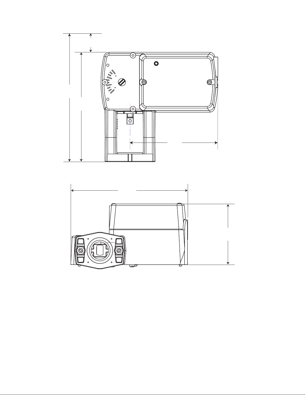
DIMENSIONAL DATA
Minimum Clearance
6-5/16
(160)
1-3/4 (45)
6-5/16
(160)
5-5/64
(129)
6-49/64
(172)
Figure-14 Mx51-710x Spring Return Valve Actuator Dimensions
Dimensions shown
are in inches (mm).
3-1/2
(89)
14 © Copyright 2008 TAC All Rights Reserved. F-27169-6
Page 15

F-27169-6 © Copyright 2008 TAC All Rights Reserved. 15
Page 16

Copyright 2008, TAC
All brand names, trademarks and registered
trademarks are the property of their respective
owners. Information contained within this
document is subject to change without notice.
F-27169-6
TAC
1354 Clifford Avenue
P.O. Box 2940
Loves Park, IL 61132-2940
www.tac.com
 Loading...